Installing and Maintaining the Cisco ASR 9000v Satellite Shelf

This chapter describes how to install the Cisco ASR 9000v satellite shelf. It contains the following sections:

Electrostatic Discharge

This section explains best practices to be followed to prevent electrostatic discharge (ESD) damage, which can occur when the equipment is improperly handled.

Before locating and grounding any chassis, you must complete the following prerequisites:

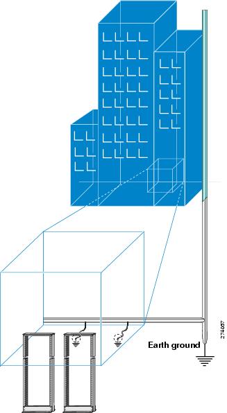
Preparing Your Location

This section illustrates how the building that houses the chassis must be properly grounded to the earth ground.


Warning

This product requires short-circuit (overcurrent) protection to be provided as part of the building installation. Install only in accordance with national and local wiring regulations. Statement 1045.


Warning

A readily accessible two-poled disconnect device must be incorporated in the fixed wiring. Statement 1022.


Figure 1. Building with Rack Room Connected to Earth Ground

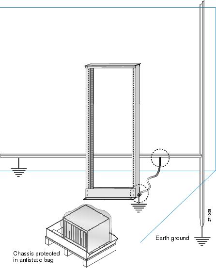
Preparing the Rack Room

This section explains how the rack enclosures must be properly connected to the building earth ground. It also illustrates how to keep the chassis in a sealed antistatic bag until you are ready to install it. (See figure below.)


DANGER

Before performing any of the following procedures, ensure that power is removed from the DC circuit. Statement 1003.


Figure 2. Rack Room Connected to Earth Ground

Preparing Yourself

This section illustrates how to prepare yourself before removing the chassis from the sealed antistatic bag. This figure illustrates how to cuff the ESD strap around the wrist and the ground cord that connects the cuff to the ground. ESD wrist straps are the primary means of controlling static charge on personnel.

Figure 3. Wearing the ESD Strap

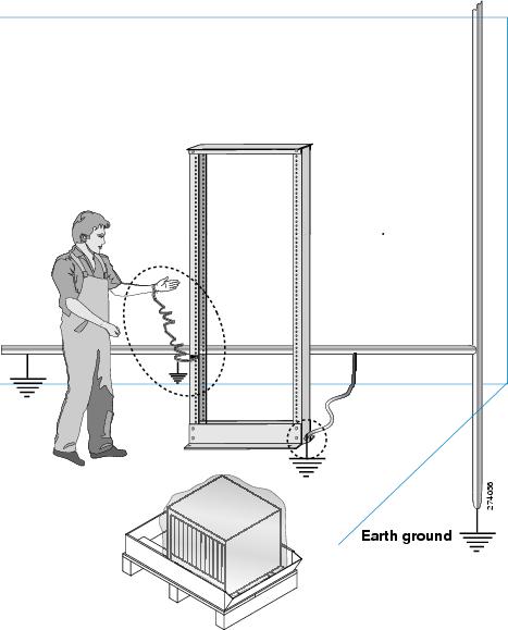
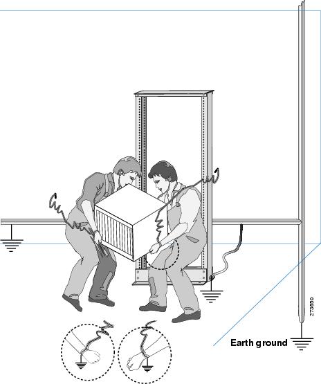
This figure illustrates how you must be properly grounded before handling the chassis.

Figure 4. Handling the Chassis

Installing the Cisco ASR 9000v Satellite Shelf

This section explains how to unpack and install the Cisco ASR 9000v satellite shelf.

Important Safety Recommendations


Warning

IMPORTANT SAFETY INSTRUCTIONS: This warning symbol means danger. You are in a situation that could cause bodily injury. Before you work on any equipment, be aware of the hazards involved with electrical circuitry and be familiar with standard practices for preventing accidents. Use the statement number provided at the end of each warning to locate its translation in the translated safety warnings that accompanied this device. Statement 1071


Warning

Installation of the equipment must comply with local and national electrical codes. Statement 1074


Warning

This unit is intended for installation in restricted access areas. A restricted access area can be accessed only through the use of a special tool, lock and key, or other means of security. Statement 1017


Warning

Ultimate disposal of this product should be handled according to all national laws and regulations. Statement 1040


Warning

A readily accessible two-poled disconnect device must be incorporated in the fixed wiring. Statement 1022


Note

In this appendix, the term “shelf” refers to the steel enclosure that holds cards and connects power, and the term “node” refers to the entire hardware and software system.

Note

Unless otherwise specified, the term “Cisco ASR 9000v satellite shelf” refers to both ANSI and ETSI environments.

Note

The Cisco ASR 9000v satellite shelf is suitable for installation in network telecommunication facilities where the National Electric Code (NEC) applies.

Required Tools and Equipment

The following sections describe the tools and equipment that you need to install and test the Cisco ASR 9000v satellite shelf.

Cisco Supplied Materials

The following materials are required and are shipped with the Cisco ASR 9000v satellite shelf (wrapped in plastic). The number in parentheses gives the quantity of the item included in the package.

  • (Only ANSI) Pair of 19-inch mounting brackets (2)
  • (Only ANSI) Pair of 23-inch mounting brackets (2)
  • (Only ETSI) Pair of 21-inch mounting brackets (2)
  • Cable guides (2)
  • Rubber bumpers (4)
  • M4 screws to fix brackets (8)
  • M4 screws to fix ground lug (2)
  • Ground lug (1)
  • Power cable (1) (A DC power cable is present in the kit if you have ordered a DC power shelf)

Note

If you have ordered an ASR-9000v-24-A=, ASR-9000v-DC-A, or ASR-9000v-DC-E= shelf, a DC power cable is present in the accessory kit. If you have ordered an ASR-9000v-AC= shelf, an AC power cable is present in the accessory kit.

Caution

Use only the power cables that are designed to be used with the Cisco ASR 9000v satellite shelf. These are sold separately.


Caution

Always use M4 screw to install the ground lug on an ASR 9000v shelf. The part number of this screw is Cisco PN 48-0468-01 and the maximum recommended length is 6 millimeters (mm). If you use any other screw longer than 6 mm, it can lead to a short circuit in the ASR 9000v shelf.


User Supplied Materials

The following materials, tools, and equipment are required but are not supplied with the Cisco ASR 9000v satellite shelf.

  • Equipment rack
  • M4 Phillips screw driver
  • Fuse panel
  • Wire cutters
  • Wire wrapper
  • Voltmeter
  • Ground cable #8 AWG stranded, specified for up to 90° Celsius (194° Fahrenheit)
  • M3 Phillips screw driver only for the ASR-9000v-24-A=, the ASR-9000v-DC-A=, and the ASR-9000v-DC-E= shelves to secure the DC power cable to the shelf.

Caution

Use only the power cables that are designed to be used with the Cisco ASR 9000v satellite shelf. These are sold separately.


Unpacking and Inspecting the Cisco ASR 9000v Satellite Shelf

Complete the following steps to remove the Cisco ASR 9000v satellite shelf from the package and verify that all parts of the Cisco ASR 9000v satellite shelf assembly are in good condition.

SUMMARY STEPS

  1. When you receive the Cisco ASR 9000v satellite shelf equipment at the installation site, open the top of the box. The Cisco Systems logo indicates the top of the box.
  2. Remove the foam inserts from the box. The box contains the Cisco ASR 9000v satellite shelf (wrapped in plastic) and other items needed for installation.
  3. To remove the Cisco ASR 9000v satellite shelf, grasp both rings of the shelf removal strap and slowly lift the shelf out of the box.
  4. Verify that you have all items listed in the Required Tools and Equipment section.
  5. Verify the following:
  6. Remove the foam inserts from the box. The box contains the Cisco ASR 9000v satellite shelf (wrapped in plastic) and other items needed for installation.
  7. If there is any damage, call your Cisco sales engineer for a replacement.

DETAILED STEPS


Step 1

When you receive the Cisco ASR 9000v satellite shelf equipment at the installation site, open the top of the box. The Cisco Systems logo indicates the top of the box.

Step 2

Remove the foam inserts from the box. The box contains the Cisco ASR 9000v satellite shelf (wrapped in plastic) and other items needed for installation.

Step 3

To remove the Cisco ASR 9000v satellite shelf, grasp both rings of the shelf removal strap and slowly lift the shelf out of the box.

Step 4

Verify that you have all items listed in the Required Tools and Equipment section.

Step 5

Verify the following:

  • The Cisco ASR 9000v satellite shelf is not damaged.
  • The cable connectors, EOBC, timing connectors, and power connectors on the front panel of the Cisco ASR 9000v satellite shelf are not damaged.
  • The SFP cages on the front panel of the Cisco ASR 9000v satellite shelf are not damaged.
Step 6

Remove the foam inserts from the box. The box contains the Cisco ASR 9000v satellite shelf (wrapped in plastic) and other items needed for installation.

Step 7

If there is any damage, call your Cisco sales engineer for a replacement.


ANSI Rack Installation

The Cisco ASR 9000v satellite shelf is mounted on a 19-inch (482.6-mm) or 23-inch (584.2-mm) equipment rack. If the shelf is mounted in the front position, then it projects 0.9 inches (22.86 mm) from the front of the rack. If the shelf assembly is mounted in the middle position, it projects 4.3 inches (109.22 mm) from the front of the rack. The shelf mounts in both Electronic Industries Alliance (EIA) standard and Telcordia-standard racks. The shelf assembly is a total of 17.4 inches (442.4 mm) wide with no mounting ears attached. Ring runs are not provided by Cisco and might hinder side-by-side installation of shelves where space is limited.

The Cisco ASR 9000v satellite shelf measures 1.7 inches (43.1 mm) high, 19 or 23 inches (482.6 or 584.2 mm) wide (depending on which way the mounting ears are attached), and 9.1 inches (231.1 mm) deep.

This figure shows the dimensions of the Cisco ASR 9000v satellite shelf in a 19-inch ANSI rack configuration with brackets mounted in the front position.

Figure 5. Cisco ASR 9000v Satellite Shelf Dimensions for a 19-Inch ANSI Rack Configuration

Mounting Brackets


Caution

Use only the fastening hardware provided with the Cisco ASR 9000v satellite shelf to prevent loosening, deterioration, and electromechanical corrosion of the hardware and joined material.


Caution

When mounting the Cisco ASR 9000v satellite shelf in a frame with a nonconductive coating (such as paint, lacquer, or enamel) either use the thread-forming screws provided with the Cisco ASR 9000v satellite shelf shipping kit or remove the coating from the threads to ensure electrical continuity.


The mounting brackets (19-inch or 23-inch) are used to mount the Cisco ASR 9000v satellite shelf on a 19-inch (482.6 mm) rack or a 23-inch (584.2 mm) rack.

Mounting a Single Node

Mounting the Cisco ASR 9000v satellite shelf on a rack requires a minimum of 1.75 inches (44.44 mm) of vertical rack space. To ensure the mounting is secure, use two #12-24 mounting screws for each side of the shelf assembly. For an ANSI rack, the brackets can be mounted in the front or middle position.

ETSI Rack Installation

The Cisco ASR 9000v satellite shelf is mounted on a 600 x 600-mm (23.6 x 23.6-inch) or 600 x 300-mm (23.6 x 11.8-inch) ETSI standard equipment rack. The shelf assembly is a total of 442 mm (17.4 inches) wide with no mounting ears attached. Cisco does not provide ring runs, which might hinder side-by-side installation of shelves where space is limited.

The Cisco ASR 9000v satellite shelf measures 43.1 mm (1.7 inches) high, 533.4 mm (21 inches) wide, and 231.1 mm (9.1 inches) deep.

Figure 1 provides the dimensions of the Cisco ASR 9000v satellite shelf installed on a 600 x 600-mm (23.6 x 23.6-inch) ETSI standard equipment rack. In this figure, the cable guides are attached to the mounting brackets.


Caution

When mounting a Cisco ASR 9000v satellite shelf in a partially filled rack, load the rack from the bottom to the top with the heaviest component at the bottom of the rack. If the rack is provided with stabilizing devices, install the stabilizers before mounting or servicing the unit in the rack.


Figure 6. Cisco ASR 9000v Satellite Shelf Dimensions for an ETSI Rack Configuration

Mounting a Single Node

The Cisco ASR 9000v satellite shelf requires 1.75 inches (44.44 mm) minimum of vertical rack space. To ensure the mounting is secure, use two M6 mounting screws for each side of the shelf assembly. In an ETSI rack, the brackets can be mounted only in the front position.

Wall Mounting and Desktop Mounting the Cisco ASR 9000v Satellite Shelf

This section provides information about mounting the Cisco ASR 9000v satellite shelf on the wall and the desktop.

  • Wall Mounting
  • Desktop Mounting
Wall Mounting

The Cisco ASR 9000v satellite shelf can be mounted on the wall using the wall mount brackets. The type of screws used to mount the brackets on the wall depends on the wall-type; wall mount brackets are not provided by Cisco.

After the Cisco ASR 9000v satellite shelf is mounted on the wall, a fire protective tray is installed on the wall mount bracket to support the shelf assembly.

Desktop Mounting

The Cisco ASR 9000v satellite shelf can be mounted on the desktop for easy access.

Laser Warning

The laser warning label is placed on top of the chassis. The following figure shows the label placed on the Cisco ASR 9000v satellite shelf.

Figure 7. Cisco ASR 9000v Satellite Shelf Label

Installing the Cisco ASR 9000v Satellite Shelf


Note

In a CO (Central Office) or CPE (Customer Premises Equipment) installation, if the Cisco ASR 9000 routers or Cisco CRS Line Card Chassis and Cisco ASR 9000v satellite shelf units are connected through copper SFP+, place the units less than 6 meters apart in the same lineup.

Warning

The intra-building port(s) of the equipment or subassembly must not be metallically connected to interfaces that connect to the OSP or its wiring. These interfaces are designed for use as intra-building interfaces only (Type 2 or Type 4 ports as described in GR-1089-CORE) and require isolation from the exposed OSP cabling. The addition of Primary Protectors is not sufficient protection in order to connect these interfaces metallically to OSP wiring. Statement 7005


Warning

Stability hazard. The rack stabilizing mechanism must be in place, or the rack must be bolted to the floor before you slide the unit out for servicing. Failure to stabilize the rack can cause the rack to tip over. Statement 1048


Warning

This product requires short-circuit (overcurrent) protection, to be provided as part of the building installation. Install only in accordance with national and local wiring regulations. Statement 1045


Warning

This product relies on the building’s installation for short-circuit (overcurrent) protection. Ensure that the protective device is rated not greater than: 10A for Cisco ASR 9000v satellite shelf with 48 VDC power supply; 15A for Cisco ASR 9000v satellite shelf with 24 VDC power supply. Statement 1005


Warning

This product relies on the building's installation for short-circuit (overcurrent) protection. Ensure that the protective device is rated not greater than: 10A-15A, 100-240 VAC~. Statement 1005


Warning

To prevent the system from overheating, do not operate it in an area that exceeds the maximum recommended ambient temperature of: 131°F (55°C) for Cisco ASR 9000v satellite shelf with AC power module and 149°F (65°C) for Cisco ASR 9000v satellite shelf with DC power module. Statement 1047


Warning

Take care when connecting units to the supply circuit so that wiring is not overloaded. Statement 1018


Warning

To prevent bodily injury when mounting or servicing this unit in a rack, you must take special precautions to ensure that the system remains stable. The following guidelines are provided to ensure your safety:This unit should be mounted at the bottom of the rack if it is the only unit in the rack.When mounting this unit in a partially filled rack, load the rack from the bottom to the top with the heaviest component at the bottom of the rack.When mounting this unit in a partially filled rack, load the rack from the bottom to the top with the heaviest component at the bottom of the rack.If the rack is provided with stabilizing devices, install the stabilizers before mounting or servicing the unit in the rack. Statement 1006


Warning

To ensure adequate airflow through the equipment rack, we recommend that you maintain a clearance of at least 6 inches (15.24 cm) on each side of the rack at all times.


Note

The Cisco ASR 9000v satellite shelf installations are suitable for Network Telecommunication facilities and locations where NEC applies.

SUMMARY STEPS

  1. Complete the necessary task as applicable:
  2. Complete the necessary mounting task as applicable:
  3. Connect the chassis to the office ground. For detailed instructions on how to ground the chassis, see the Electrostatic Discharge section.

DETAILED STEPS


Step 1

Complete the necessary task as applicable:

Step 2

Complete the necessary mounting task as applicable:

Step 3

Connect the chassis to the office ground. For detailed instructions on how to ground the chassis, see the Electrostatic Discharge section.


Mounting the 19-Inch Brackets on the Cisco ASR 9000v Satellite Shelf for the ANSI Rack Configuration


Caution

Use only the fastening hardware provided with the Cisco ASR 9000v satellite shelf to prevent loosening, deterioration, and electromechanical corrosion of the hardware and joined material.


Caution

When mounting the Cisco ASR 9000v satellite shelf in a frame with a nonconductive coating (such as paint, lacquer, or enamel), either use the thread-forming screws provided with the Cisco ASR 9000v satellite shelf ship kit or remove the coating from the threads to ensure electrical continuity.


Note

The mounting brackets can be installed in the front or the middle position of the chassis.

SUMMARY STEPS

  1. Place the wider side of the 19-inch mounting bracket flush against the Cisco ASR 9000v satellite shelf, as shown in Figure 1. The narrow side of the mounting bracket should be towards the front of the shelf.
  2. Align the mounting bracket screw holes against the shelf assembly screw holes.
  3. Insert the M4 flat screws and tighten them to a torque value of 11.5 in-lb (1.3 N-m).
  4. Repeat Step 1 to Step 3 to mount the bracket on the opposite side.

DETAILED STEPS


Step 1

Place the wider side of the 19-inch mounting bracket flush against the Cisco ASR 9000v satellite shelf, as shown in Figure 1. The narrow side of the mounting bracket should be towards the front of the shelf.

Step 2

Align the mounting bracket screw holes against the shelf assembly screw holes.

Step 3

Insert the M4 flat screws and tighten them to a torque value of 11.5 in-lb (1.3 N-m).

Step 4

Repeat Step 1 to Step 3 to mount the bracket on the opposite side.

Figure 8. Mounting the Brackets on the Cisco ASR 9000v Satellite Shelf for the ANSI Rack Configuration

Mounting the 23-Inch Brackets on the Cisco ASR 9000v Satellite Shelf for the ANSI Rack Configuration


Caution

Use only the fastening hardware provided with the Cisco ASR 9000v satellite shelf to prevent loosening, deterioration, and electromechanical corrosion of the hardware and joined material.


Caution

When mounting the Cisco ASR 9000v satellite shelf in a frame with a nonconductive coating (such as paint, lacquer, or enamel), either use the thread-forming screws provided with the Cisco ASR 9000v satellite shelf ship kit or remove the coating from the threads to ensure electrical continuity.


Note

The mounting brackets can be installed in the front or the middle position of the chassis.

SUMMARY STEPS

  1. Place the wider side of the 23-inch mounting bracket flush against the Cisco ASR 9000v satellite shelf, as shown in the figure Mounting the Brackets on the Cisco ASR 9000v Satellite Shelf for a 23-Inch (584.2-mm) ANSI Rack Configuration. The narrow side of the mounting bracket should be towards the front of the shelf.
  2. Align the mounting bracket screw holes against the shelf assembly screw holes.
  3. Insert the M4 flat screws and tighten them to a torque value of 11.5 in-lb (1.3 N-m).
  4. Repeat Step 1 to Step 3 to mount the bracket on the opposite side.
  5. Align the cable guide screw hole against the mount bracket screw hole, as shown in this figure.
  6. Insert the M4 screw and tighten it to a torque value of 6.5 in-lb (0.75 N-m).
  7. Repeat Step 5 and Step 6 to install the cable guide on the opposite side.

DETAILED STEPS


Step 1

Place the wider side of the 23-inch mounting bracket flush against the Cisco ASR 9000v satellite shelf, as shown in the figure Mounting the Brackets on the Cisco ASR 9000v Satellite Shelf for a 23-Inch (584.2-mm) ANSI Rack Configuration. The narrow side of the mounting bracket should be towards the front of the shelf.

Step 2

Align the mounting bracket screw holes against the shelf assembly screw holes.

Step 3

Insert the M4 flat screws and tighten them to a torque value of 11.5 in-lb (1.3 N-m).

Step 4

Repeat Step 1 to Step 3 to mount the bracket on the opposite side.

Figure 9. Mounting the Brackets on the Cisco ASR 9000v Satellite Shelf for a 23-Inch (584.2-mm) ANSI Rack Configuration
Step 5

Align the cable guide screw hole against the mount bracket screw hole, as shown in this figure.

Figure 10. Mounting the Cable Guide on the Cisco ASR 9000v Satellite Shelf 23-Inch (584.2-mm) Mounting Bracket
Step 6

Insert the M4 screw and tighten it to a torque value of 6.5 in-lb (0.75 N-m).

Note 
The cable guide is made of plastic. Therefore a lower torque value should be applied to tighten the cable guide screws to avoid breakage.
Step 7

Repeat Step 5 and Step 6 to install the cable guide on the opposite side.


Mounting the Brackets on the Cisco ASR 9000v Satellite Shelf for the ETSI Rack Configuration


Caution

Use only the fastening hardware provided with the Cisco ASR 9000v satellite shelf to prevent loosening, deterioration, and electromechanical corrosion of the hardware and joined material.


Caution

When mounting the Cisco ASR 9000v satellite shelf in a frame with a nonconductive coating (such as paint, lacquer, or enamel), either use the thread-forming screws provided with the Cisco ASR 9000v satellite shelf ship kit or remove the coating from the threads to ensure electrical continuity.


Note

The mounting brackets can be installed in the front or the middle position of the chassis.

SUMMARY STEPS

  1. Place the mounting bracket flush against the Cisco ASR 9000v satellite shelf, as shown in the figure Mounting the Brackets on the Cisco ASR 9000v Satellite Shelf for the ANSI Rack Configuration.
  2. Align the mounting bracket screw holes against the shelf assembly screw holes.
  3. Insert the M4 flat screws and tighten them to a torque value of 11.5 in-lb (1.3 N-m).
  4. Repeat Step 1 to Step 3 to mount the bracket on the opposite side.
  5. Align the cable guide screw hole against the mount bracket screw hole, as shown in this figure.
  6. Insert the M4 screw and tighten it to a torque value of 6.5 in-lb (0.75 N-m).
  7. Repeat Step 5 and Step 6 to install the cable guide on the opposite side.

DETAILED STEPS


Step 1

Place the mounting bracket flush against the Cisco ASR 9000v satellite shelf, as shown in the figure Mounting the Brackets on the Cisco ASR 9000v Satellite Shelf for the ANSI Rack Configuration.

Step 2

Align the mounting bracket screw holes against the shelf assembly screw holes.

Step 3

Insert the M4 flat screws and tighten them to a torque value of 11.5 in-lb (1.3 N-m).

Step 4

Repeat Step 1 to Step 3 to mount the bracket on the opposite side.

Figure 11. Mounting the Brackets on the Cisco ASR 9000v Satellite Shelf for the ANSI Rack Configuration
Step 5

Align the cable guide screw hole against the mount bracket screw hole, as shown in this figure.

Figure 12. Mounting the Cable Guide on the Cisco ASR 9000v Satellite Shelf ETSI Mounting Bracket
Step 6

Insert the M4 screw and tighten it to a torque value of 6.5 in-lb (0.75 N-m).

Note 
The cable guide is made of plastic. Therefore a lower torque value should be applied to tighten the cable guide screws to avoid breakage.
Step 7

Repeat Step 5 and Step 6 to install the cable guide on the opposite side.


Mounting the Cisco ASR 9000v Satellite Shelf on a Rack (One Person)

SUMMARY STEPS

  1. Verify that the proper fuse panel has been installed in the top mounting space. If a fuse panel is not present, you must install one according to manufacturer instructions:
  2. Ensure that the shelf assembly is mounted on the appropriate rack equipment:
  3. Lift the shelf to the desired position in the rack.
  4. Align the screw holes on the mounting brackets with the mounting holes in the rack.
  5. Using the Phillips Dynamometric screwdriver, install one mounting screw in each side of the assembly:
  6. When the shelf assembly is secured to the rack, install the remaining two mounting screws on either sides of the shelf assembly.

DETAILED STEPS


Step 1

Verify that the proper fuse panel has been installed in the top mounting space. If a fuse panel is not present, you must install one according to manufacturer instructions:

  • For a 48 VDC power supply, the fuse rating must not exceed 10 A.

  • For a 24 VDC power supply, the fuse rating must not exceed 15 A.

  • For an AC power supply, the fuse rating must not exceed 10 A or 15 A, depending on the standards in various countries. The overcurrent and short circuit protection must be in accordance with local and national electrical codes.

Note 
In an ANSI rack, the Cisco ASR 9000v satellite shelf chassis can be installed in the front or the middle position. In an ETSI rack, the Cisco ASR 9000v satellite shelf chassis can be installed only in the front position.
Note 
The Cisco ASR 9000v satellite shelf requires a minimum of 1.75 inches (44.44 mm) of vertical rack space. To ensure that the mounting is secure, use two M6 mounting screws on each side of the shelf for ETSI rack installation, and two 12-24 x 3/4 pan-head Phillips mounting screws on each side of the shelf for ANSI rack installation. A Cisco ASR 9000v satellite shelf assembly should be mounted at the bottom of the rack if it is the only unit in the rack.
Step 2

Ensure that the shelf assembly is mounted on the appropriate rack equipment:

  • 23 inches (584.2 mm) or 19 inches (482.6 mm) for ANSI racks

  • 600 x 600-mm (23.6 x 23.6-inch) or 600 x 300-mm (23.6 x 11.8-inch) for ETSI racks.

  • For an AC power supply, the fuse rating must not exceed 10 A or 15 A, depending on the standards in various countries. The overcurrent and short circuit protection must be in accordance with local and national electrical codes. Diagram 1 of the figure Mounting a Cisco ASR 9000v Satellite Shelf in a Rackshows the Cisco ASR 9000v satellite shelf mounted on an ANSI rack in the middle position using 19-inch mounting brackets. Diagram 2 of the figure Mounting a Cisco ASR 9000v Satellite Shelf in a Rack shows the Cisco ASR 9000v satellite shelf mounted on an ETSI rack in the front position using mounting brackets.

Figure 13. Mounting a Cisco ASR 9000v Satellite Shelf in a Rack
Step 3

Lift the shelf to the desired position in the rack.

Step 4

Align the screw holes on the mounting brackets with the mounting holes in the rack.

Step 5

Using the Phillips Dynamometric screwdriver, install one mounting screw in each side of the assembly:

  • For an ANSI rack, use 12-24 x 3/4 pan-head Phillips mounting screws and tighten it to a torque value of 22 in-lb (2.5 Nm)

  • For an ETSI rack, use M6 mounting screws and tighten it to a torque value of 22 in-lb (2.5 Nm)

Step 6

When the shelf assembly is secured to the rack, install the remaining two mounting screws on either sides of the shelf assembly.


Mounting the Cisco ASR 9000v Satellite Shelf on the Wall

SUMMARY STEPS

  1. Verify that the proper fuse panel has been installed in the top mounting space. If a fuse panel is not present, you must install one according to manufacturer instructions:
  2. Mount the bracket on the wall, as shown in the figure Wall Mounting of the Cisco ASR 9000v Satellite Shelf. To mount the bracket on a non-concrete wall, choose the bracket holes based on the wall structure. At least four screws must be used to mount the bracket on the wall. Based on the wall material, apply the torque value provided by the screw vendor.
  3. Align the mounting bracket screw holes against the shelf screw holes, as shown in diagram 1 of the figure Wall Mounting of the Cisco ASR 9000v Satellite Shelf.
  4. Insert six M4 pan-head screws and tighten them to a torque value of 11.5 in-lb (1.3 N-m), as shown in diagram 2 of the figure Wall Mounting of the Cisco ASR 9000v Satellite Shelf.
  5. Align the fire protective drip tray screw holes against the wall mounting bracket screw holes, as shown in diagram 1 of the figure Mounting the Fire Protective Cover. The fire protective drip tray is present in the wall mount accessory kit provided by Cisco.
  6. Insert two M4 pan-head screws and tighten them to a torque value of 11.5 in-lb (1.3 N-m), as shown in diagram 2 of the figure Mounting the Fire Protective Cover.

DETAILED STEPS


Step 1

Verify that the proper fuse panel has been installed in the top mounting space. If a fuse panel is not present, you must install one according to manufacturer instructions:

  • For a 48 VDC power supply, the fuse rating must not exceed 10 A.

  • For a 24 VDC power supply, the fuse rating must not exceed 15 A.

  • For an AC power supply, the fuse rating must not exceed 10 A or 15 A, depending on the standards in various countries. The overcurrent and short circuit protection must be in accordance with local and national electrical codes.

Note 
The Cisco ASR 9000v satellite shelf requires a minimum of 23.65 inches (600-mm) vertical length and a minimum of 15.75 inches (400-mm) horizontal width on the wall. Wall mount brackets are used to mount the Cisco ASR 9000v satellite shelf on the wall. The type of screws used to mount the brackets on the wall depends on the wall-type; wall mount brackets are not provided by Cisco. The screws used must be able to sustain an overall weight of at least 10 kg (22 lb).
Step 2

Mount the bracket on the wall, as shown in the figure Wall Mounting of the Cisco ASR 9000v Satellite Shelf. To mount the bracket on a non-concrete wall, choose the bracket holes based on the wall structure. At least four screws must be used to mount the bracket on the wall. Based on the wall material, apply the torque value provided by the screw vendor.

Step 3

Align the mounting bracket screw holes against the shelf screw holes, as shown in diagram 1 of the figure Wall Mounting of the Cisco ASR 9000v Satellite Shelf.

Step 4

Insert six M4 pan-head screws and tighten them to a torque value of 11.5 in-lb (1.3 N-m), as shown in diagram 2 of the figure Wall Mounting of the Cisco ASR 9000v Satellite Shelf.

Figure 14. Wall Mounting of the Cisco ASR 9000v Satellite Shelf
Step 5

Align the fire protective drip tray screw holes against the wall mounting bracket screw holes, as shown in diagram 1 of the figure Mounting the Fire Protective Cover. The fire protective drip tray is present in the wall mount accessory kit provided by Cisco.

The part number of the fire protective drip tray is Cisco PN 700-31762-XX. The product identifier (PID) of the wall mount accessory kit is CPT-50-BRKTWM= and the part number is Cisco PN 53-3513-XX.

Step 6

Insert two M4 pan-head screws and tighten them to a torque value of 11.5 in-lb (1.3 N-m), as shown in diagram 2 of the figure Mounting the Fire Protective Cover.

Figure 15. Mounting the Fire Protective Cover

Mounting the Cisco ASR 9000v Satellite Shelf on the Desktop

SUMMARY STEPS

  1. Verify that the proper fuse panel has been installed in the top mounting space. If a fuse panel is not present, you must install one according to manufacturer instructions:
  2. Locate the rubber bumpers provided in the accessory tool kit.
  3. Place the Cisco ASR 9000v satellite shelf upside down on a smooth, flat surface.
  4. Peel off the rubber bumpers from the adhesive strip and place it adhesive-side down onto all the four corners of the surface, as shown in this figure.
  5. Place the Cisco ASR 9000v satellite shelf on a desktop, or on a smooth, flat surface.

DETAILED STEPS


Step 1

Verify that the proper fuse panel has been installed in the top mounting space. If a fuse panel is not present, you must install one according to manufacturer instructions:

  • For a 48 VDC power supply, the fuse rating must not exceed 10 A.

  • For a 24 VDC power supply, the fuse rating must not exceed 15 A.

  • For an AC power supply, the fuse rating must not exceed 10 A or 15 A, depending on the standards in various countries. The overcurrent and short circuit protection must be in accordance with local and national electrical codes.

Step 2

Locate the rubber bumpers provided in the accessory tool kit.

Step 3

Place the Cisco ASR 9000v satellite shelf upside down on a smooth, flat surface.

Step 4

Peel off the rubber bumpers from the adhesive strip and place it adhesive-side down onto all the four corners of the surface, as shown in this figure.

Figure 16. Desktop Mounting of the Cisco ASR 9000v Satellite Shelf
Step 5

Place the Cisco ASR 9000v satellite shelf on a desktop, or on a smooth, flat surface.


Connecting the Chassis Ground and Power

Ground the equipment according to Telcordia standards or local practices. The following sections describe how to power and ground the Cisco ASR 9000v satellite shelf.


Note

For detailed instructions on grounding the Cisco ASR 9000v satellite shelf, see the Electrostatic Discharge.

ANSI Power and Ground

For AC power feed, use the power cable shipped with the Cisco ASR 9000v satellite shelf. For an AC power supply, the fuse rating must not exceed 10 A or 15 A, depending on the standards in various countries. The overcurrent and short circuit protection must be in accordance with local and national electrical codes. The voltage rating value for AC power ranges between 100 VAC to 240 VAC depending on the standards in various countries. This product is intended for use on the TN and TT power systems.

The Cisco ASR 9000v satellite shelf for 48 VDC power supply has redundant –48 VDC #14 single-hole lug power terminals. The terminals are labeled RET(A), RET(B), –48V(A), and –48V(B) on the power module, as shown in this figure.

Figure 17. Cisco ASR 9000v Satellite Shelf for 48 VDC Power Supply

The Cisco ASR 9000v satellite shelf for 24 VDC power supply has redundant –24 VDC #14 single-hole lug power terminals. The terminals are labeled RET(A), RET(B), –24V(A), and –24V(B) on the power module.

To install redundant DC power feeds, use four power cables and one ground cable. For a single power feed, only two power cables (#14 AWG or larger, copper conductor, 194 degrees Fahrenheit [90 degrees Celsius] minimum) and one ground cable (#8 AWG or larger) are required. Use a conductor with low impedance to ensure circuit overcurrent protection. However, the conductor must have the capability to safely conduct any faulty current that might be imposed.

For a 24 VDC power supply, the fuse rating must not exceed 15 A. The voltages –20 VDC and –28.3 VDC are, respectively, the minimum and maximum voltages required to power the chassis. The nominal steady state voltage is –24 VDC.

For a 48 VDC power supply, the fuse rating must not exceed 10 A. The voltages –40.5 VDC and –57.6 VDC are, respectively, the minimum and maximum voltages required to power the chassis. Functionality is guaranteed at –40 VDC input voltage, according to GR-1089, Issue 5. The nominal steady state voltage is –48 VDC.

We recommend the following wiring conventions, but customer conventions prevail:

  • Red wire for battery connections (–48 VDC or –24 VDC).
  • Black wire for battery return connections (RET).
  • The battery return connection is treated as DC-1, as defined in Telcordia GR-1089-CORE, Issue 5.

The ground lug must be a dual-hole type, UL Listed, CSA certified, and rated to accept the #8 AWG cable. Two ground threaded holes with M4 screws are provided on the Cisco ASR 9000v satellite shelf to accommodate the dual-hole lug, as shown in the figure Ground Points on the Cisco ASR 9000v Satellite Shelf.


Caution

Always use M4 screw to install the ground lug on an ASR 9000v shelf. The part number of this screw is Cisco PN 48-0468-01 and the maximum recommended length is 6 millimeters (mm). If you use any other screw longer than 6 mm, it can lead to a short circuit in the ASR 9000v shelf.


Figure 18. Ground Points on the Cisco ASR 9000v Satellite Shelf

ETSI Power and Ground

The Cisco ASR 9000v satellite shelf for ETSI has redundant –48 VDC power connectors (DSUB for DC power module) on the DC power module. To install redundant power feeds, use the power cable shipped with the Cisco ASR 9000v satellite shelf and one ground cable. For a DC power supply, the fuse rating must not exceed 10 A. The voltages –40.5 VDC and –57.6 VDC are, respectively, the minimum and maximum voltages required to power the chassis. The nominal steady state voltage is –48 VDC.

For AC power feed, use the power cable shipped with the Cisco ASR 9000v satellite shelf. For an AC power supply, the fuse rating must not exceed 10 A or 15 A, depending on the standards in various countries. The overcurrent and short circuit protection must be in accordance with local and national electrical codes. The voltage rating value for AC power ranges between 100 VAC to 240 V AC depending on the standards in various countries. This product is intended for use on the TN and TT power systems.


Caution

Use only the power cable shipped with the Cisco ASR 9000v satellite shelf (Cisco PN 72-4974-XX/PID CPT-DC-CBL-E=).


Grounding the Cisco ASR 9000v Satellite Shelf

Before locating and grounding the Cisco ASR 9000v satellite shelf, you must complete the prerequisites mentioned in the Electrostatic Discharge.


Warning

This equipment must be grounded. Never defeat the ground conductor or operate the equipment in the absence of a suitably installed ground conductor. Contact the appropriate electrical inspection authority or an electrician if you are uncertain that suitable grounding is available. Statement 1024.


Warning

Use copper conductors only. Statement 1025.


Warning

When installing or replacing the unit, the ground connection must always be made first and disconnected last. Statement 1046.


Caution

Always use M4 screw to install the ground lug on an ASR 9000v shelf. The part number of this screw is Cisco PN 48-0468-01 and the maximum recommended length is 6 millimeters (mm). If you use any other screw longer than 6 mm, it can lead to a short circuit in the ASR 9000v shelf.


A #6 AWG cable or a 1 inch wide flat copper braid (with minimum total strands count of 1050 x 36 AWG or 260 x 36 AWG) is mandatory to install the Cisco ASR 9000v satellite shelf.

SUMMARY STEPS

  1. Verify that the office ground cable is connected to the top of the bay and the office ground, according to local site practice. (See Figure 1 and Figure 1.)
  2. Remove any paint and other nonconductive coatings from the surfaces between the shelf ground and bay frame ground point. Clean the mating surfaces and apply appropriate antioxidant compound to the bare conductors.
  3. Attach one end of the shelf ground cable (#8 AWG cable) to the ground point (rear or lateral) on the chassis using the specified dual-hole lug connector. (See diagrams 1 and 2 in the figure Grounding the Cisco ASR 9000v Satellite Shelf.)
  4. Tighten the lug using the M4 pan-head screw to torque value of 11.5 in-lb (1.3 N-m).
  5. Attach the other end of the shelf ground cable to the bay frame using a dual-hole lug connector according to the equipment bay frame specifications. (See diagram 3 in the figure Grounding the Cisco ASR 9000v Satellite Shelf.)

DETAILED STEPS


Step 1

Verify that the office ground cable is connected to the top of the bay and the office ground, according to local site practice. (See Figure 1 and Figure 1.)

Note 
The Cisco ASR 9000v satellite shelf installations are suitable for Network Telecommunication facilities and locations where NEC applies.
Note 
Additional ground cables may be added depending on local site practice. The Cisco ASR 9000v satellite shelf is designated only for a Common Bonding Network (CBN), according to the GR-1089-CORE Issue 5 (sec 9.3) definitions.
Note 
The DC power battery return (BR) terminal or positive terminal must be grounded at the source end (power feed or DC mains power end). The DC power BR input terminal is not connected to the equipment frame (chassis), so it is configured as DC-1 according to the GR-1089-CORE, Issue 5 (sec 9.8.3) definitions.
Step 2

Remove any paint and other nonconductive coatings from the surfaces between the shelf ground and bay frame ground point. Clean the mating surfaces and apply appropriate antioxidant compound to the bare conductors.

Step 3

Attach one end of the shelf ground cable (#8 AWG cable) to the ground point (rear or lateral) on the chassis using the specified dual-hole lug connector. (See diagrams 1 and 2 in the figure Grounding the Cisco ASR 9000v Satellite Shelf.)

Step 4

Tighten the lug using the M4 pan-head screw to torque value of 11.5 in-lb (1.3 N-m).

Note 
Ground points are present on the rear and lateral sides of the Cisco ASR 9000v satellite shelf (see diagram 1 in the figure Grounding the Cisco ASR 9000v Satellite Shelf). You can connect the grounding cable to either the rear or the lateral side. Diagrams 2 and 3 in the figure Grounding the Cisco ASR 9000v Satellite Shelf show the ground connection to the rear side of the Cisco ASR 9000v satellite shelf.
Step 5

Attach the other end of the shelf ground cable to the bay frame using a dual-hole lug connector according to the equipment bay frame specifications. (See diagram 3 in the figure Grounding the Cisco ASR 9000v Satellite Shelf.)

Figure 19. Grounding the Cisco ASR 9000v Satellite Shelf

Installing the Power Feeds and Ground to the Cisco ASR 9000v Satellite Shelf


Note

Before you install the power feeds to the Cisco ASR 9000v satellite shelf, connect the chassis to the office ground. For detailed instructions on how to ground the chassis, see the Grounding the Cisco ASR 9000v Satellite Shelf.

Warning

This equipment must be grounded. Never defeat the ground conductor or operate the equipment in the absence of a suitably installed ground conductor. Contact the appropriate electrical inspection authority or an electrician if you are uncertain that suitable grounding is available. Statement 1024


Warning

To reduce the risk of electric shock, switch on the power only after the power cord is completely installed into the power module. Statement 390


Warning

When stranded wiring is required, use approved wiring terminations, such as closed-loop or spade-type with upturned lugs. These terminations should be the appropriate size for the wires and should clamp both the insulation and conductor. Statement 1002


Warning

Before performing any of the following procedures, ensure that power is removed from the DC circuit. Statement 1003


Warning

Before working on a chassis or working near power supplies, unplug the power cord on AC units; disconnect the power at the circuit breaker on DC units. Statement 12


Warning

This equipment must be grounded. Never defeat the ground conductor or operate the equipment in the absence of a suitably installed ground conductor. Contact the appropriate electrical inspection authority or an electrician if you are uncertain that suitable grounding is available. Statement 1024


Warning

Use copper conductors only. Statement 1025


Warning

Connect the unit only to DC power source that complies with the safety extra-low voltage (SELV) requirements in IEC 60950 based safety standards. Statement 1033


Warning

This product requires short-circuit (overcurrent) protection, to be provided as part of the building installation. Install only in accordance with national and local wiring regulations. Statement 1045


Warning

This product relies on the building’s installation for short-circuit (overcurrent) protection. Ensure that the protective device is rated not greater than: 10A for Cisco ASR 9000v satellite shelf with 48 VDC power supply; 15A for Cisco ASR 9000v satellite shelf with 24 VDC power supply. Statement 1005


Warning

This product relies on the building's installation for short-circuit (overcurrent) protection. Ensure that the protective device is rated not greater than: 10A-15A, 100-240 VAC~. Statement 1005


Warning

A readily accessible two-poled disconnect device must be incorporated in the fixed wiring. Statement 1022


Warning

This unit might have more than one power supply connection. All connections must be removed to de-energize the unit. Statement 1028


Caution

Always use M4 screw to install the ground lug on an ASR 9000v shelf. The part number of this screw is Cisco PN 48-0468-01 and the maximum recommended length is 6 millimeters (mm). If you use any other screw longer than 6 mm, it can lead to a short circuit in the ASR 9000v shelf.


Caution

Always use the supplied ESD wristband when working with a powered Cisco ASR 9000v satellite shelf. For detailed instructions on how to wear the ESD wristband, see the Electrostatic Discharge.


Caution

Do not operate the Cisco ASR 9000v satellite shelf without an air filter.


Note

Replacement or cleaning of an air filter is recommended every 60 days. Air filters are replaceable or reusable.

SUMMARY STEPS

  1. Verify that the correct fuse panel is installed in the top mounting space:
  2. Depending on the shelf and the power module installed, complete the necessary task:
  3. Complete the Turning On and Verifying Office Power (AC) on the Cisco ASR 9000v Satellite Shelf or Turning On and Verifying Office Power (DC) on the Cisco ASR 9000v Satellite Shelf as necessary.

DETAILED STEPS


Step 1

Verify that the correct fuse panel is installed in the top mounting space:

  • For a 48 VDC power supply, the fuse rating must not exceed 10 A.
  • For a 24 VDC power supply, the fuse rating must not exceed 15 A.
  • For an AC power supply, the fuse rating must not exceed 10 A or 15 A, depending on the standards in various countries. The overcurrent and short circuit protection must be in accordance with local and national electrical codes.
Step 2

Depending on the shelf and the power module installed, complete the necessary task:

Step 3

Complete the Turning On and Verifying Office Power (AC) on the Cisco ASR 9000v Satellite Shelf or Turning On and Verifying Office Power (DC) on the Cisco ASR 9000v Satellite Shelf as necessary.


Connecting Office Power (AC) to the Cisco ASR 9000v Satellite Shelf


Note

This product is intended for use on the TN and TT power systems.

Warning

When installing or replacing the unit, the ground connection must always be made first and disconnected last. Statement 1046


Warning

This equipment shall be connected to AC mains provided with a surge protective device (SPD) at the service equipment complying with NFPA 70, the National Electrical Code (NEC). Statement 7012


Caution

The Cisco ASR 9000v satellite shelf relies on the protective devices in the building installation to protect against short circuit, overcurrent, and ground faults. Ensure that the protective devices are properly rated and comply with national and local codes.


Caution

When terminating the frame ground, do not use soldering lug connectors, screwless (push-in) connectors, quick connect connectors, or other friction-fit connectors.


Note

If the Cisco ASR 9000v satellite shelf loses its connection to the Cisco ASR 9000 Router or Cisco CRS Line Card Chassis, the Cisco ASR 9000v satellite shelf resets until the connection to the Cisco ASR 9000 Router or Cisco CRS Line Card Chassis is re-established.

SUMMARY STEPS

  1. Attach the AC power cable to the cable connector in the AC power module, as shown in this figure.
  2. Close the cable clip to secure the power cable, as shown in this figure.
  3. Connect the power cable to the fuse panel or power source.

DETAILED STEPS


Step 1

Attach the AC power cable to the cable connector in the AC power module, as shown in this figure.

Figure 20. Connecting Office Power to the Cisco ASR 9000v Satellite Shelf—AC Power
Step 2

Close the cable clip to secure the power cable, as shown in this figure.

Figure 21. Closing the Cable Clip to Secure the Power Cable to the Cisco ASR 9000v Satellite Shelf
Step 3

Connect the power cable to the fuse panel or power source.

Note 
The voltage rating value for AC power ranges between 100 VAC to 240 VAC depending on the standards in various countries.

Connecting Office Power (DC) to the Cisco ASR 9000v Satellite Shelf (ANSI Only)


Warning

When installing or replacing the unit, the ground connection must always be made first and disconnected last. Statement 1046


Warning

Hazardous voltage or energy may be present on power terminals. Always replace cover when terminals are not in service. Be sure uninsulated conductors are not accessible when cover is in place. Statement 1086


Note

The battery return connection is treated as DC-1, as defined in Telcordia GR-1089-CORE Issue 5.

Caution

The Cisco ASR 9000v satellite shelf relies on the protective devices in the building installation to protect against short circuit, overcurrent, and ground faults. Ensure that the protective devices are properly rated and comply with national and local codes.


Note

If the Cisco ASR 9000v satellite shelf loses its connection to the Cisco ASR 9000 Router or Cisco CRS Line Card Chassis, the Cisco ASR 9000v satellite shelf resets until the connection to the Cisco ASR 9000 Router or Cisco CRS Line Card Chassis is re-established.

SUMMARY STEPS

  1. Connect the return cables of the power supply to the earth ground located at the power supply side.
  2. Connect the office power according to the fuse panel engineering specifications.
  3. Measure and cut the cables as needed to reach the Cisco ASR 9000v satellite shelf from the fuse panel.
  4. Dress the power according to local site practice.
  5. Strip 1/2 inch (12.7 mm) of insulation from all power cables that you will use.
  6. Crimp the lugs onto the ends of all the power leads.
  7. Remove the terminal block protective cover, as shown in this figure.
  8. Untighten the terminal block screws, as shown in this figure.
  9. Insert the lugs, as shown in this figure.
  10. Tighten the M3.5 screws to a torque value of 7 in-lb (0.79 N-m) to lock the lugs.
  11. Mount the terminal block protective cover on the Cisco ASR 9000v satellite shelf, as shown in this figure.

DETAILED STEPS


Step 1

Connect the return cables of the power supply to the earth ground located at the power supply side.

Step 2

Connect the office power according to the fuse panel engineering specifications.

Step 3

Measure and cut the cables as needed to reach the Cisco ASR 9000v satellite shelf from the fuse panel.

Step 4

Dress the power according to local site practice.

Step 5

Strip 1/2 inch (12.7 mm) of insulation from all power cables that you will use.

Step 6

Crimp the lugs onto the ends of all the power leads.

Step 7

Remove the terminal block protective cover, as shown in this figure.

Figure 22. Removing the Terminal Block Protective Cover on the Cisco ASR 9000v Satellite Shelf
Step 8

Untighten the terminal block screws, as shown in this figure.

Figure 23. Loosening the Terminal Block Screws on the Cisco ASR 9000v Satellite Shelf
Step 9

Insert the lugs, as shown in this figure.

Figure 24. Inserting the Lugs on the Cisco ASR 9000v Satellite Shelf
Step 10

Tighten the M3.5 screws to a torque value of 7 in-lb (0.79 N-m) to lock the lugs.

Step 11

Mount the terminal block protective cover on the Cisco ASR 9000v satellite shelf, as shown in this figure.

Figure 25. Replacing the Terminal Block Protective Cover on the Cisco ASR 9000v Satellite Shelf
Note 
Use only pressure terminal connectors, such as ring and fork types, when terminating the battery, battery return, and frame ground conductors.
Caution 

Before you make any crimp connections, coat all bare conductors (battery, battery return, and frame ground) with an appropriate antioxidant compound. Bring all unplated connectors, braided strap, and bus bars to a bright finish, then coat with an antioxidant before you connect them. You do not need to prepare tinned, solder-plated, or silver-plated connectors and other plated connection surfaces, but always keep them clean and free of contaminants.

Caution 

When terminating power, return (RET), and frame ground, do not use soldering lug, screwless (push-in) connectors, quick-connect, or other friction-fit connectors.


Connecting Office Power (DC) to the Cisco ASR 9000v Satellite Shelf (ETSI Only)


Warning

When installing or replacing the unit, the ground connection must always be made first and disconnected last. Statement 1046


Warning

Hazardous voltage or energy may be present on power terminals. Always replace cover when terminals are not in service. Be sure uninsulated conductors are not accessible when cover is in place. Statement 1086


Note

The battery return connection is treated as DC-1, as defined in Telcordia GR-1089-CORE Issue 5.

Caution

The Cisco ASR 9000v satellite shelf relies on the protective devices in the building installation to protect against short circuit, overcurrent, and ground faults. Ensure that the protective devices are properly rated and comply with national and local codes.


Note

If the Cisco ASR 9000v satellite shelf loses its connection to the Cisco ASR 9000 Router or Cisco CRS Line Card Chassis, the Cisco ASR 9000v satellite shelf resets until the connection to the Cisco ASR 9000 Router or Cisco CRS Line Card Chassis is re-established.

SUMMARY STEPS

  1. Connect the return cables of the power supply to the earth ground located at the power supply side.
  2. Attach the DC ETSI power cables to the DSUB power connectors of the DC power module, as shown in this figure.
  3. Tighten the M3 pan-head screws to a torque value of 4 in-lb (0.45 N-m) to secure the cable, as shown in this figure.

DETAILED STEPS


Step 1

Connect the return cables of the power supply to the earth ground located at the power supply side.

Step 2

Attach the DC ETSI power cables to the DSUB power connectors of the DC power module, as shown in this figure.

Figure 26. Connecting DC ETSI Power Cables to the DSUB Power Connectors on the Cisco ASR 9000v Satellite Shelf
Step 3

Tighten the M3 pan-head screws to a torque value of 4 in-lb (0.45 N-m) to secure the cable, as shown in this figure.

Figure 27. Securing the DC Power Cables to the Cisco ASR 9000v Satellite Shelf
Note 
Use only pressure terminal connectors, such as ring and fork types, when terminating the battery, battery return, and frame ground conductors.
Caution 

Before you make any crimp connections, coat all bare conductors (battery, battery return, and frame ground) with an appropriate antioxidant compound. Bring all unplated connectors, braided strap, and bus bars to a bright finish, then coat with an antioxidant before you connect them. You do not need to prepare tinned, solder-plated, or silver-plated connectors and other plated connection surfaces, but always keep them clean and free of contaminants.

Caution 

When terminating power, return (RET), and frame ground, do not use soldering lug, screwless (push-in) connectors, quick-connect, or other friction-fit connectors.


Turning On and Verifying Office Power (AC) on the Cisco ASR 9000v Satellite Shelf


Note

Before you turn on the power on the Cisco ASR 9000v satellite shelf, ensure that the chassis is connected to the office ground. For detailed instructions on how to ground the chassis, see the Grounding the Cisco ASR 9000v Satellite Shelf.

DANGER

To reduce the risk of electric shock, switch on the power only after the power cord is completely installed into the power module. Statement 390


Note

Do not apply power to the shelf assembly until you complete all the installation steps.

SUMMARY STEPS

  1. To power up the node, insert the fuse into the fuse position according to site practice. For an AC power supply, the fuse rating must not exceed 10 A or 15 A, depending on the standards in various countries.
  2. If the Cisco ASR 9000v satellite shelf does not power up, check the voltage at the power source using a voltmeter. The voltage should be 100 VAC to 240 VAC ±10 percent.

DETAILED STEPS


Step 1

To power up the node, insert the fuse into the fuse position according to site practice. For an AC power supply, the fuse rating must not exceed 10 A or 15 A, depending on the standards in various countries.

Step 2

If the Cisco ASR 9000v satellite shelf does not power up, check the voltage at the power source using a voltmeter. The voltage should be 100 VAC to 240 VAC ±10 percent.


Turning On and Verifying Office Power (DC) on the Cisco ASR 9000v Satellite Shelf


Note

Before you turn on the power on the Cisco ASR 9000v satellite shelf, ensure that the chassis is connected to the office ground. For detailed instructions on how to ground the chassis, see the Grounding the Cisco ASR 9000v Satellite Shelf.

DANGER

To reduce the risk of electric shock, switch on the power only after the power cord is completely installed into the power module. Statement 390


Note

Do not apply power to the shelf assembly until you complete all the installation steps.

SUMMARY STEPS

  1. Using a voltmeter, verify the office battery and ground at the following points on the fuse panel:
  2. To power up the node, insert the fuse into the fuse position according to site practice. For a 24 VDC power supply, the fuse rating must not exceed 15 A. For a 48 VDC power supply, the fuse rating must not exceed 10 A.
  3. Using a voltmeter, verify the Cisco ASR 9000v satellite shelf for –48 VDC or –24 VDC battery and return:

DETAILED STEPS


Step 1

Using a voltmeter, verify the office battery and ground at the following points on the fuse panel:

  1. To verify the power, place the black test lead of the voltmeter to the return (RET). Place the red test lead on the BAT-A connection and verify that:

    • For a 24 V DC power supply, the voltage is between –20 V DC and –28.3 V DC. Place the red test lead on the BAT-B connection and verify that it is between –20 VDC and –28.3 V DC
    Note 
    The voltages –20 VDC and –28.3 VDC are, respectively, the minimum and maximum voltages required to power the Cisco ASR 9000v satellite shelf that has 24 VDC power supply. The nominal steady state voltage is –24 VDC.
    • For a 48 VDC power supply, the voltage is between –40.5 VDC and –57.6 VDC. Place the red test lead on the BAT-B connection and verify that it is between –40.5 VDC and –57.6 VDC.
    Note 
    The voltages –40.5 VDC and –57.6 VDC are, respectively, the minimum and maximum voltages required to power the Cisco ASR 9000v satellite shelf that has 48 VDC power supply. The nominal steady state voltage is –48 VDC.
  2. To verify the ground, place the black test lead of the voltmeter to the frame ground. Place the red test lead on the BAT-A return ground and verify that no voltage is present, that is, meter reading must be 0 VDC. Place the red test lead on the BAT-B return ground and verify that no voltage is present, that is, that the meter reading is 0 VDC.

Step 2

To power up the node, insert the fuse into the fuse position according to site practice. For a 24 VDC power supply, the fuse rating must not exceed 15 A. For a 48 VDC power supply, the fuse rating must not exceed 10 A.

Step 3

Using a voltmeter, verify the Cisco ASR 9000v satellite shelf for –48 VDC or –24 VDC battery and return:

  1. To verify the BAT-A of the Cisco ASR 9000v satellite shelf, place the black lead of the voltmeter to the return. Place the red test lead to the –48-V or –24-V (BAT-A battery connection) red cable. For a 48-VDC power supply, verify that it reads between –40.5 VDC and –57.6 VDC. For a 24-VDC power supply, verify that the voltage reads between –20 VDC and –28.3 VDC. Then place the red test lead of the voltmeter to the RET1 (BAT-A return ground) black cable and verify that no voltage is present, that is, that the meter reading is 0 VDC.

    Note 
    For a Cisco ASR 9000v satellite shelf that has a 24-VDC power supply, the voltages –20 VDC and –28.3 VDC are, respectively, the minimum and maximum voltages required to power the Cisco ASR 9000v satellite shelf. The nominal steady state voltage is –24 VDC. To prevent damage to the Cisco ASR 9000v satellite shelf, the voltage must not exceed –30 VDC.
    Note 
    For a Cisco ASR 9000v satellite shelf that has a 48-VDC power supply, the voltages –40.5 VDC and –57.6 VDC are, respectively, the minimum and maximum voltages required to power the Cisco ASR 9000v satellite shelf. The nominal steady state voltage is –48 VDC.
  2. To verify the BAT-B of the Cisco ASR 9000v satellite shelf, place the black test lead of the voltmeter to the return. Place the red test lead to the –48-V or –24-V(BAT-B battery connection) red cable. For a 48-VDC power supply, verify that it reads between –40.5 VDC and –57.6 VDC. For a 24-VDC power supply, verify that the voltage reads between –20 VDC and –28.3 VDC.Then place the red test lead of the voltmeter to the RET2 (BAT-B return ground) black cable and verify that no voltage is present, that is, that the meter reading is 0 VDC.

  3. To verify the ground, place the black test lead of the voltmeter to the frame ground. Place the red test lead on the BAT-A return ground and verify that no voltage is present, that is, that the meter reading is 0 VDC. Place the red test lead on the BAT-B return ground and verify that no voltage is present, that is, that the meter reading is 0 VDC.


Connecting Cables to the EOBC, Timing, and Console Ports on the Cisco ASR 9000v Satellite Shelf


Note

Before you perform this procedure, ensure that the chassis is connected to the office ground. For detailed instructions on how to ground the chassis, see the Grounding the Cisco ASR 9000v Satellite Shelf.

Caution

Always use the supplied Electrostatic Discharge (ESD) wristband when working with a powered Cisco ASR 9000v satellite shelf. For detailed instructions on how to wear the ESD wristband, see the Preparing Yourself.


SUMMARY STEPS

  1. Complete the Connecting the Timing Cables to the PPS, 10-MHz, and ToD/PPS Ports on the Cisco ASR 9000v Satellite Shelf procedure to connect timing to external equipment.
  2. Complete the Connecting Cables to the EOBC, Timing, and Console Ports on the Cisco ASR 9000v Satellite Shelf procedure to install the cables to the EOBC or console port.

DETAILED STEPS


Step 1

Complete the Connecting the Timing Cables to the PPS, 10-MHz, and ToD/PPS Ports on the Cisco ASR 9000v Satellite Shelf procedure to connect timing to external equipment.

Step 2

Complete the Connecting Cables to the EOBC, Timing, and Console Ports on the Cisco ASR 9000v Satellite Shelf procedure to install the cables to the EOBC or console port.


Connecting the Timing Cables to the PPS, 10-MHz, and ToD/PPS Ports on the Cisco ASR 9000v Satellite Shelf


Note

Before you perform this procedure, ensure that the chassis is connected to the office ground. For detailed instructions on how to ground the chassis, see the Grounding the Cisco ASR 9000v Satellite Shelf.

Warning

The intra-building port(s) of the equipment or subassembly must not be metallically connected to interfaces that connect to the OSP or its wiring. These interfaces are designed for use as intra-building interfaces only (Type 2 or Type 4 ports as described in GR-1089-CORE) and require isolation from the exposed OSP cabling. The addition of Primary Protectors is not sufficient protection in order to connect these interfaces metallically to OSP wiring.Statement 7005


Note

For rules about provisioning timing references, see ITU-T G.813.

Note

To unplug the RJ-45 cables connected to the ToD/PPS and EOBC ports on the fan tray, use small pliers or a screwdriver.

SUMMARY STEPS

  1. Locate the timing connectors (PPS, 10 MHz, or ToD/PPS) on the fan tray assembly of the Cisco ASR 9000v satellite shelf, as shown in this figure.
  2. To connect the PPS or 10 MHz port:
  3. To connect the ToD/PPS RJ-45 output port:

DETAILED STEPS


Step 1

Locate the timing connectors (PPS, 10 MHz, or ToD/PPS) on the fan tray assembly of the Cisco ASR 9000v satellite shelf, as shown in this figure.

Figure 28. Timing Connectors (PPS, 10 MHz, or ToD/PPS) on the Fan Tray Assembly
Step 2

To connect the PPS or 10 MHz port:

  1. Connect one end of the mini-BNC cable to the PPS or 10 MHz mini-BNC output port.

  2. Connect the other end of the mini-BNC cable to external equipment to provide timing signals.

Step 3

To connect the ToD/PPS RJ-45 output port:

  1. Connect one end of a standard CAT-5 Ethernet cable to the ToD/PPS RJ-45 output port.

  2. Connect the other end of the CAT-5 Ethernet cable to an external equipment to provide timing signals.


Connecting the Cables to the EOBC or Console Port on the Cisco ASR 9000v Satellite Shelf


Note

Before you perform this procedure, ensure that the chassis is connected to the office ground. For detailed instructions on how to ground the chassis, see the Grounding the Cisco ASR 9000v Satellite Shelf.

Warning

The intra-building port(s) of the equipment or subassembly must not be metallically connected to interfaces that connect to the OSP or its wiring. These interfaces are designed for use as intra-building interfaces only (Type 2 or Type 4 ports as described in GR-1089-CORE) and require isolation from the exposed OSP cabling. The addition of Primary Protectors is not sufficient protection in order to connect these interfaces metallically to OSP wiring. Statement 7005


Note

The console port is used for the setup and maintenance of the Cisco ASR 9000v satellite shelf. The EOBC port is used for disaster recovery, that is, to log in to the Cisco ASR 9000v satellite shelf for troubleshooting when the connection between the Cisco ASR 9000v satellite shelf and the Cisco ASR 9000 router or Cisco CRS Line Card Chassis is lost.

Note

To unplug the RJ-45 cables connected to the ToD/PPS and EOBC ports on the fan tray, use small pliers or a screwdriver.

SUMMARY STEPS

  1. Locate the EOBC port or the console port on the fan tray assembly of the Cisco ASR 9000v satellite shelf, as shown in Figure 1.
  2. To connect the EOBC port:
  3. To connect the console port:

DETAILED STEPS


Step 1

Locate the EOBC port or the console port on the fan tray assembly of the Cisco ASR 9000v satellite shelf, as shown in Figure 1.

Figure 29. EOBC or Console Port on the Fan Tray Assembly
Step 2

To connect the EOBC port:

  1. Connect one end of a standard CAT-5 Ethernet cable to the EOBC port.

  2. Connect the other end of the standard CAT-5 Ethernet cable to external equipment to establish external connectivity.

Step 3

To connect the console port:

  1. Connect one end of the USB cable to the console port.

  2. Connect the other end of the USB cable to the console terminal or a modem that connects to the console terminal.


Installing and Routing Fiber-Optic Cables


Note

Before you perform this procedure, ensure that the chassis is connected to the office ground. For detailed instructions on how to ground the chassis, see the Grounding the Cisco ASR 9000v Satellite Shelf.

Warning

Invisible laser radiation may be emitted from disconnected fibers or connectors. Do not stare into beams or view directly with optical instruments. Statement 1051


Caution

When connecting an optical-fiber patch cord between the Cisco ASR 9000v satellite shelf and the optical card ports in the Cisco ASR 9000 router or Cisco CRS Line Card Chassis, use the electrostatic discharge wristband supplied with the Cisco ASR 9000 router or Cisco CRS Line Card Chassis.


Note

Always clean all the fiber connectors thoroughly before making the connection with the mating adapter. Very small particles can permanently damage the end of the mating fiber inside the Cisco ASR 9000v satellite shelf, which makes regular cleaning imperative. For cleaning instructions, see Cleaning Fiber Connectors.

Note

The Cisco ASR 9000v satellite shelf features LC/UPC bulkhead adapters. Always use fiber-optic cables equipped with the corresponding (LC/UPC) connector type. Using any other type of connector results in damage to the connector or adapter, or both.

SUMMARY STEPS

  1. Place the LC/UPC cable connector in front of the corresponding bulkhead adapter on the front panel of the Cisco ASR 9000v satellite shelf.
  2. Align the keyed ridge of the cable connector with the slot in the receiving adapter.
  3. Gently push the cable connector into the adapter until you hear a click, which indicates that the latching system is engaged.
  4. Route the fiber cables through the cable guide (left and right side). A tie-wrap is tied around the fiber and cables through the cable guide.

DETAILED STEPS


Step 1

Place the LC/UPC cable connector in front of the corresponding bulkhead adapter on the front panel of the Cisco ASR 9000v satellite shelf.

Step 2

Align the keyed ridge of the cable connector with the slot in the receiving adapter.

Step 3

Gently push the cable connector into the adapter until you hear a click, which indicates that the latching system is engaged.

Step 4

Route the fiber cables through the cable guide (left and right side). A tie-wrap is tied around the fiber and cables through the cable guide.

The cables are routed through the cable guide in an ANSI (23-inch) rack configuration, as shown in this figure.

Figure 30. Cable Management in an ANSI Rack Configuration

The cables are routed through the cable guide in an ETSI rack configuration, as shown in this figure.

Figure 31. Cable Management in an ETSI Rack Configuration
Note 
If no cable guide is installed, bind the cables and fibers using the tie-wrap.

Performing the Cisco ASR 9000v Satellite Shelf Installation Acceptance Test

SUMMARY STEPS

  1. Once you have installed your Cisco ASR 9000v satellite shelf, verify that you have completed each applicable procedure listed in this table.
  2. Inspecting the Cisco ASR 9000v Satellite Shelf Installation and Connections.
  3. Measuring DC Voltage on the Cisco ASR 9000v Satellite Shelf.
  4. Continue with Performing the Cisco ASR 9000v Satellite Shelf Installation Acceptance Test.

DETAILED STEPS


Step 1

Once you have installed your Cisco ASR 9000v satellite shelf, verify that you have completed each applicable procedure listed in this table.

Table 1. Procedure Summary for Installing the Cisco ASR 9000v Satellite Shelf

Procedure

Completed

Unpacking and Inspecting the Cisco ASR 9000v Satellite Shelf

Connect the chassis to the office ground. For detailed instructions on how to ground the chassis, see the Electrostatic Discharge section.

Installing the Power Feeds and Ground to the Cisco ASR 9000v Satellite Shelf

Connecting Cables to the EOBC, Timing, and Console Ports on the Cisco ASR 9000v Satellite Shelf

Installing and Routing Fiber-Optic Cables

Step 2

Inspecting the Cisco ASR 9000v Satellite Shelf Installation and Connections.

Step 3

Measuring DC Voltage on the Cisco ASR 9000v Satellite Shelf.

Step 4

Continue with Performing the Cisco ASR 9000v Satellite Shelf Installation Acceptance Test.


Inspecting the Cisco ASR 9000v Satellite Shelf Installation and Connections

SUMMARY STEPS

  1. Make sure that all external wiring connections (that is, power, ground, alarms, and so on) are secure. If a wire or cable is loose, return to the appropriate procedure in this chapter to correct it.

DETAILED STEPS


Make sure that all external wiring connections (that is, power, ground, alarms, and so on) are secure. If a wire or cable is loose, return to the appropriate procedure in this chapter to correct it.


Measuring DC Voltage on the Cisco ASR 9000v Satellite Shelf


Warning

To reduce the risk of electric shock, switch on the power only after the power cord is completely installed into the power module. Statement 390


Caution

Do not apply power to the shelf assembly until you complete all the installation steps.


SUMMARY STEPS

  1. Using a voltmeter, verify the office battery and ground at the following points on the fuse panel:
  2. Using a voltmeter, verify the shelf ground and power wiring: Place the black lead (positive) on the RET1(A) and the red lead on the –48 V (A) or –24 V (A) point.
  3. Using a voltmeter, verify the Cisco ASR 9000v satellite shelf for –48 VDC or –24 VDC battery and return:

DETAILED STEPS


Step 1

Using a voltmeter, verify the office battery and ground at the following points on the fuse panel:

  1. To verify the power, place the black test lead of the voltmeter to the return (RET). Hold it there while completing Step b.

  2. Place the red test lead on the fuse power points on the third-party power distribution panel to verify that they read between:

    • For a 48-VDC power supply, the voltage is between –40.5 VDC and –57.6 VDC. Place the red test lead on the BAT-B connection and verify that it is between –40.5 VDC and –57.6 VDC.
    • For a 24-VDC power supply, the voltage is between –20 VDC and –28.3 VDC. Place the red test lead on the BAT-B connection and verify that it is between –20 VDC and –28.3 VDC.
    Note 
    The voltages –40.5 VDC and –57.6 VDC are, respectively, the minimum and maximum voltages required to power the Cisco ASR 9000v satellite shelf with a 48-VDC power supply. The nominal steady state voltage is –48 VDC.
    Note 
    The voltages –20 VDC and –28.3 VDC are, respectively, the minimum and maximum voltages required to power the Cisco ASR 9000v satellite shelf with a 24-VDC power supply. The nominal steady state voltage is –24 VDC.
Step 2

Using a voltmeter, verify the shelf ground and power wiring: Place the black lead (positive) on the RET1(A) and the red lead on the –48 V (A) or –24 V (A) point.

  • For the Cisco ASR 9000v satellite shelf with 48 V power supply, verify a reading between –40.5 VDC and –57.6 VDC.
  • For the Cisco ASR 9000v satellite shelf with 24V power supply, verify a reading between –20 VDC and –28.3 VDC.

If there is no voltage, check the following and correct if necessary:

  • Battery and ground are reversed to the shelf.
  • Battery is open or missing.
  • Return is open or missing.
Step 3

Using a voltmeter, verify the Cisco ASR 9000v satellite shelf for –48 VDC or –24 VDC battery and return:

  1. To verify the BAT-A of the Cisco ASR 9000v satellite shelf, place the black lead of the voltmeter to the return. Place the red test lead to the –48-V or –24-V (BAT-A battery connection) red cable. For a 48-VDC power supply, verify that it reads between –40.5 VDC and –57.6 VDC. For a 24-VDC power supply, verify that it reads between –20 VDC and –28.3 VDC. Then place the red test lead of the voltmeter to the RET1 (BAT-A return ground) black cable and verify that no voltage is present, that is, that the meter reading is 0 VDC.

    Note 
    For a Cisco ASR 9000v satellite shelf that has 24 VDC power supply, the voltages –20 VDC and –28.3 VDC. are, respectively, the minimum and maximum voltages required to power the Cisco ASR 9000v satellite shelf. The nominal steady state voltage is –24 VDC.
    Note 
    For a Cisco ASR 9000v satellite shelf that has 48 VDC power supply, the voltages –40.5 VDC and –57.6 VDC. are, respectively, the minimum and maximum voltages required to power the Cisco ASR 9000v satellite shelf. The nominal steady state voltage is –48 VDC.
  2. To verify the BAT-B of the Cisco ASR 9000v satellite shelf, place the black test lead of the voltmeter to the return. Place the red test lead to the –48 V o4 –24 V(BAT-B battery connection) red cable. For a 48-VDC power supply, verify that it reads between –40.5 VDC and –57.6 VDC. For a 24-VDC power supply, verify that it reads between –20 VDC and –28.3 VDC. Then place the red test lead of the voltmeter to the RET2 (BAT-B return ground) black cable and verify that no voltage is present, that is, that the meter reading is 0 VDC.


Maintaining the Cisco ASR 9000v Satellite Shelf

Air Filter Overview

The Cisco ASR 9000v satellite shelf contains a preinstalled reusable air filter (15454 M2-FTF) on the right side of the shelf.

The reusable filter is made up of a gray, open-cell, polyurethane foam that is specially coated to provide fire and fungi resistance. Spare filters should be kept in stock. The air filter can be replaced without removing the fan tray assembly. However, the fan tray must be turned off to remove the air filter.

A periodic health check of the air filter, every 3 months depending on the level of dust in the environment, will help to avoid over-clogging of the air filter and provide better life.The Cisco ASR 9000v satellite shelf’s air filter may be used as a single-use or be reused depending on local deployment requirements.

  • If reuse of the air filter is prohibited, it should be replaced every six months with a new air filter (15454 M2-FTF), as described in the Replacing the Air Filter in the Cisco ASR 9000v Satellite Shelf section.
  • If reuse of the air filter is permitted, the filter media can be cleaned with slightly compressed air, vacuumed, or rinsed with clean water. If a degreaser is required, use only a mild detergent such as dishwashing liquid. Avoid cleaning the air filter with harsh cleaning agents or solvents. If the air filter is cleaned with water, it should be completely dry before reinstalling. Even though the air filter can be cleaned, replacement is recommended every two to three years to ensure media durability and to eliminate residual dust build-up and subsequent air flow resistance.

Caution

Do not operate a Cisco ASR 9000v satellite shelf without the mandatory air filter.


Replacing the Air Filter in the Cisco ASR 9000v Satellite Shelf


Note

Before you perform this procedure, ensure that the chassis is connected to the office ground. For detailed instructions on how to ground the chassis, see the Grounding the Cisco ASR 9000v Satellite Shelf.

Caution

Do not operate the Cisco ASR 9000v satellite shelf without an air filter.


Note

Replacement or cleaning of an air filter is recommended every 60 days. Air filters are replaceable or reusable.

SUMMARY STEPS

  1. Loosen the screw on the air filter faceplate, as shown in this figure.
  2. Extract the air filter from the Cisco ASR 9000v satellite shelf, as shown in this figure.
  3. Remove the air filter faceplate from the air filter frame, as shown in this figure.
  4. Clean or replace the air filter.
  5. Insert the air filter faceplate engaging the air filter frame, as shown in this figure.
  6. Insert the air filter into the Cisco ASR 9000v satellite shelf.
  7. Tighten the M3 screw on the air filter to a torque value of 4 in-lb (0.45 N-m).

DETAILED STEPS


Step 1

Loosen the screw on the air filter faceplate, as shown in this figure.

Figure 32. Removing the Air Filter in the Cisco ASR 9000v Satellite Shelf
Step 2

Extract the air filter from the Cisco ASR 9000v satellite shelf, as shown in this figure.

Figure 33. Extracting the Air Filter in the Cisco ASR 9000v Satellite Shelf
Step 3

Remove the air filter faceplate from the air filter frame, as shown in this figure.

Figure 34. Removing the Air Filter from the Air Filter Faceplate
Step 4

Clean or replace the air filter.

Step 5

Insert the air filter faceplate engaging the air filter frame, as shown in this figure.

Figure 35. Attach the Air Filter Faceplate to the Air Filter Frame
Step 6

Insert the air filter into the Cisco ASR 9000v satellite shelf.

Step 7

Tighten the M3 screw on the air filter to a torque value of 4 in-lb (0.45 N-m).


Fan Tray Assembly

The fan tray assembly is preinstalled on the right side of the Cisco ASR 9000v satellite shelf. The fan tray assembly is removable and holds fans and fan-control circuitry for the Cisco ASR 9000v satellite shelf. The fan tray assembly should be accessed only if a fan failure occurs.

The fan tray assembly has the following ports:

  • EOBC (Ethernet Out-of-Band Channel)—An RJ-45 port that supports high bandwidth external connectivity. If the Cisco ASR 9000v satellite shelf fails to boot up, the EOBC port also called as the disaster recovery port is used to log in to the Cisco ASR 9000v satellite shelf for troubleshooting.

Note

The EOBC port is meant for usage only by TAC (Technical Assistance Center).
  • PPS (Pulse Per Second)—A mini-BNC output port that provides timing signals to an external equipment from the Cisco ASR 9000v satellite shelf.
  • 10MH—A mini-BNC output port that provides timing signals at a frequency of 10 MHz to an external equipment from the Cisco ASR 9000v satellite shelf and RET for power terminals A and B.
  • ToD/PPS (Time of Day/Pulse Per Second)—An RJ-45 serial output port that provides time and day information and timing signals to an external equipment from the Cisco ASR 9000v satellite shelf.
  • CONSOLE—A USB port that is used to connect a console terminal. The console terminal can be one of the following:
    • An ASCII terminal or a PC running terminal emulation software
    • A modem

The following figure shows the ports on the fan tray assembly:

Figure 36. Ports on the Fan Tray Assembly

The console port provides access to the Cisco ASR 9000v satellite shelf either locally (using a console terminal), or remotely (using a modem). Console connections transmit at slower speeds than modems; therefore, the console connection is suited for use with console terminals.


Note

An RJ-45 serial port is used for TOD/PPS functionality. The two RJ-45 pins 7 and 8 is used for TOD (Time Of Day) functionality and the other two RJ-45 pins 1 and 2 are used for PPS functionality. Even though an RJ-45 cable is used for TOD/PPS connection, a serial link is established. Two mini coax connectors with RG316 1.0/2.3 M/M cables (50 ohm) are used for PPS (Pulse Per Second) and for 10MHz sinusoidal signal. Cable for TOD/PPS and 10MHz shall be shielded.

Note

For rules about provisioning timing references, see Telcordia SR-NWT-002224.

Fan Speed

Fan speed is controlled by the microprocessor present in the Cisco ASR 9000v satellite shelf. The sensors measure the critical component temperature of the Cisco ASR 9000v satellite shelf. Fan speed options are low, medium, and high.

Fan Failure

If one or more fans fail on the fan tray assembly, replace the entire assembly. You cannot replace individual fans. The red Fan Fail LED on the front of the Cisco ASR 9000v satellite shelf illuminates when one or more fans fail. The red Fan Fail LED clears after you install a working fan tray.

Replacing the Fan Tray Assembly in the Cisco ASR 9000v Satellite Shelf


Note

Before you perform this procedure, ensure that the chassis is connected to the office ground. For detailed instructions on how to ground the chassis, see the Grounding the Cisco ASR 9000v Satellite Shelf.

Caution

Do not operate the Cisco ASR 9000v satellite shelf without an air filter.


Note

The estimated time for a skilled technician to replace an equipment fan or fan tray is 2 minutes.

Note

The fan or the cooling unit can be replaced without service interruption.

Caution

Do not force a fan tray module into place. Doing so can damage either the connectors on the fan tray or the connectors on the back panel of the shelf assembly, or both.


Note

Error messages appear on the fan tray LED and in Cisco IOS XR software when the fan tray module is removed from the shelf or when one fan is not working.

SUMMARY STEPS

  1. Loosen the screw on the fan tray assembly, as shown in this figure.
  2. Extract the fan tray assembly partially (not more than 1 inch) to disconnect the backplane connector and wait until the fan stops.
  3. When the fans have stopped, pull the fan tray assembly completely out of the shelf, as shown in this figure.
  4. Slide the new fan tray assembly into the Cisco ASR 9000v satellite shelf until the electrical plug at the rear of the tray plugs into the corresponding receptacle on the backplane.
  5. Tighten the M3 screw on the fan tray assembly to a torque value of 4 in-lb (0.45 N-m).

DETAILED STEPS


Step 1

Loosen the screw on the fan tray assembly, as shown in this figure.

Figure 37. Fan Tray Assembly in the Cisco ASR 9000v Satellite Shelf
Step 2

Extract the fan tray assembly partially (not more than 1 inch) to disconnect the backplane connector and wait until the fan stops.

Step 3

When the fans have stopped, pull the fan tray assembly completely out of the shelf, as shown in this figure.

Figure 38. Fan Tray Assembly in the Cisco ASR 9000v Satellite Shelf Extracted
Step 4

Slide the new fan tray assembly into the Cisco ASR 9000v satellite shelf until the electrical plug at the rear of the tray plugs into the corresponding receptacle on the backplane.

Step 5

Tighten the M3 screw on the fan tray assembly to a torque value of 4 in-lb (0.45 N-m).


Cleaning Fiber Connectors

Required Tools and Equipment

You need the following tools and equipment:

  • Inspection microscope
  • Type A Fiber Optic Connector Cleaner (CLETOP reel)
  • Optical swab
  • Optical receiver cleaning stick

Warning

Invisible laser radiation may be emitted from the end of the unterminated fiber cable or connector. Do not view directly with optical instruments. Viewing the laser output with certain optical instruments (for example, eye loupes, magnifiers, and microscopes) within a distance of 100 mm may pose an eye hazard. Statement 1056


SUMMARY STEPS

  1. Using an inspection microscope, inspect each fiber connector for dirt, cracks, or scratches.
  2. Replace any damaged fiber connectors.
  3. Complete the Cleaning Fiber Connectors with CLETOP as necessary.
  4. Complete the Cleaning Fiber Adapters as necessary.

DETAILED STEPS


Step 1

Using an inspection microscope, inspect each fiber connector for dirt, cracks, or scratches.

Step 2

Replace any damaged fiber connectors.

Note 
Replace all dust caps whenever the equipment is unused for 30 minutes or more.
Step 3

Complete the Cleaning Fiber Connectors with CLETOP as necessary.

Step 4

Complete the Cleaning Fiber Adapters as necessary.

Note 
To clean multi-fiber optic connectors, complete the Cleaning Multi-Fiber Optic Cable Connectors as necessary.

Cleaning Multi-Fiber Optic Cable Connectors


Warning

Invisible laser radiation may be emitted from disconnected fibers or connectors. Do not stare into beams or view directly with optical instruments. Statement 1051


SUMMARY STEPS

  1. Remove the protective cap on the optical-fiber cable connector.
  2. Read the manufacturer (cleaning cartridge) instructions to insert the connector into the cleaning cartridge.
  3. Slide the lever on the cartridge to swipe the connector surface.
  4. Insert the fiber connector into the applicable adapter or attach a dust cap to the fiber connector.

DETAILED STEPS


Step 1

Remove the protective cap on the optical-fiber cable connector.

Step 2

Read the manufacturer (cleaning cartridge) instructions to insert the connector into the cleaning cartridge.

Step 3

Slide the lever on the cartridge to swipe the connector surface.

Step 4

Insert the fiber connector into the applicable adapter or attach a dust cap to the fiber connector.

Note 
If you must replace a dust cap on a connector, first verify that the dust cap is clean.

Cleaning Fiber Connectors with CLETOP

Required Tools and Equipment

You need the following tools and equipment:

  • Type A Fiber Optic Connector Cleaner (CLETOP reel)
  • Optical receiver cleaning stick

SUMMARY STEPS

  1. Remove the dust cap from the fiber connector.
  2. Press the lever up to open the shutter door. Each time you press the lever, you expose a clean wiping surface.
  3. Insert the connector into the CLETOP cleaning cassette slot, rotate one quarter turn, and gently swipe downwards.
  4. Use an inspection microscope to inspect each fiber connector for dirt, cracks, or scratches. If the connector is not clean, repeat Steps 1 to 3.
  5. Insert the fiber connector into the applicable adapter or attach a dust cap to the fiber connector.

DETAILED STEPS


Step 1

Remove the dust cap from the fiber connector.

Step 2

Press the lever up to open the shutter door. Each time you press the lever, you expose a clean wiping surface.

Step 3

Insert the connector into the CLETOP cleaning cassette slot, rotate one quarter turn, and gently swipe downwards.

Step 4

Use an inspection microscope to inspect each fiber connector for dirt, cracks, or scratches. If the connector is not clean, repeat Steps 1 to 3.

Step 5

Insert the fiber connector into the applicable adapter or attach a dust cap to the fiber connector.

Note 
If you must replace a dust cap on a connector, first verify that the dust cap is clean. To clean the dust cap, wipe the outside of the cap using a dry, lint-free wipe and the inside of the dust cap using a CLETOP stick swab (14100400).

Cleaning Fiber Adapters

SUMMARY STEPS

  1. Remove the dust plug from the fiber adapter.
  2. Insert a CLETOP stick swab (14100400) into the adapter opening and rotate the swab.
  3. Place dust plugs on the fiber adapters when not in use.

DETAILED STEPS


Step 1

Remove the dust plug from the fiber adapter.

Step 2

Insert a CLETOP stick swab (14100400) into the adapter opening and rotate the swab.

Step 3

Place dust plugs on the fiber adapters when not in use.


Next Steps

For information on powering up your system, see the “Plug and Play Satellite nV Switch Turn Up” section in the “Configuring the Satellite Network Virtualization (nV) System on the Cisco ASR 9000 Series Router” chapter of the Cisco ASR 9000 Series Aggregation Services Router InV System Configuration Guide.