Monitoring the Control Plane
To verify the overall health of your system, monitor control plane resources on a regular basis.
Avoiding Problems Through Regular Monitoring
Monitoring system resources allows you to detect potential problems before they happen, thus avoiding outages. The following are show the advantages of regular monitoring:
- In a real-life example, customers installed new line cards. After the line cards were in operation for a few years, lack of memory on those line cards caused major outages in some cases. Monitoring memory usage would have identified a memory issue and avoided an outage.
- Regular monitoring establishes a baseline for a normal system load. You can use this information as a basis for comparison when you upgrade hardware or software—to see if the upgrade has affected resource usage.
Control Plane Overview
The following sections contain a high-level overview of the control plane:
Cisco ASR 1000 Series Routers Control Plane Architecture
The major components in the control plane are:
- Cisco ASR 1000 Series Route Processor (RP)—A general purpose CPU responsible for routing protocols, CLI, network management interfaces, code storage, logging, and chassis management. The Cisco ASR 1000 Series RPs process network control packets as well as protocols not supported by the Cisco ASR 1000 Series ESP.
- Cisco ASR 1000 Series Embedded Services Processor (ESP)—A forwarding processor that handles forwarding control plane traffic, and performs packet processing functions such as firewall inspection, ACLs, encryption, and QoS.
- Cisco ASR 1000 Series SPA Interface Processor (SIP)—An interface processor that provides the connection between the Route Processor and the shared port adapters (SPAs).
Distributed Control Plane Architecture
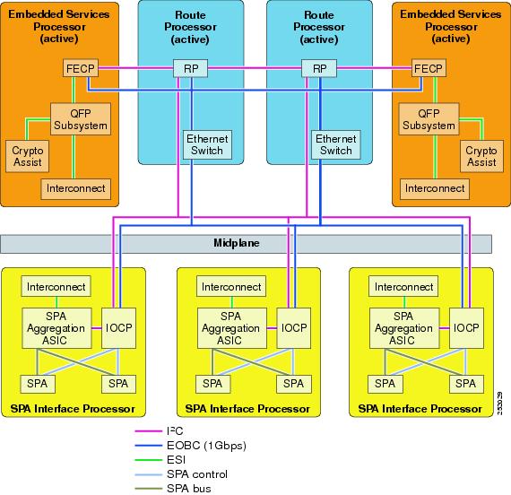
Cisco ASR 1000 Series Routers have a distributed control plane architecture. A separate control processor is embedded on each major component in the control plane, as shown in Figure 2-1:
The RP manages and maintains the control plane using a dedicated Gigabit Ethernet out-of-band channel (EOBC). The internal EOBC is used to continuously exchange system state information among the different major components. For example, in the event of a failure condition, a switchover event occurs and the standby RP and ESP are immediately ready to assume the data forwarding functions or the control plane functions for the failed component.
The inter-integrated circuit (I2C) monitors the health of hardware components. The Enhanced SerDes Interconnect (ESI) is a set of serial links that are the data path links on the midplane connecting the RP, SIPs, and standby ESPs to the active ESP.
Figure 2-1 Cisco ASR 1000 Series Routers Control Plane Architecture
The control plane processors perform the following functions:
- Runs the router control plane (Cisco IOS), including processing network control packets, computing routes, and setting up connections.
- Monitors interface and environmental status, including management ports, LEDs, alarms, and SNMP network management.
- Downloads code to other components in the system.
- Selects the active RP and ESP and synchronizes the standby RP and ESP.
- Manages logging facilities, on-board failure logging (OBFL), and statistics aggregation.
Cisco IOS XE Software Architecture
The control plane processors run Cisco IOS XE software, which is an operating system that consists of a Linux-based kernel and a common set of operating system-level utility programs. It is a distributed software architecture that moves many operating system responsibilities out of the IOS process.
In this architecture, IOS runs as one of many Linux processes while allowing other Linux processes to share responsibility for running the router. IOS runs as a user process on the RP. Hardware-specific components have been removed from the IOS process and are handled by separate middleware processes in Cisco IOS XE software. If a hardware-specific issue is discovered, the middleware process can be modified without touching the IOS process.
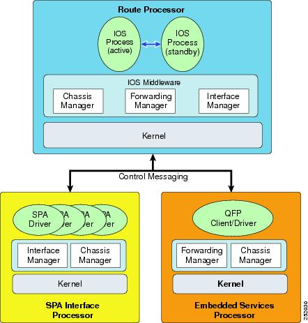
Figure 2-2 shows the main components of the Cisco IOS XE software architecture. This modular architecture increases network resiliency by distributing operating responsibility among separate processes. The architecture also allows for better allocation of memory so the router can run more efficiently.
All of the Cisco IOS XE software modules run in their own protective memory spaces, which facilitates fault containment. Any software outages of an individual software module are localized to that particular module. All other software processes continue to operate. For example, for each SPA, a separate driver process is executed on the SIP, even if multiple SPAs of the same type are present. Because each SPA driver runs in its own protective memory, failure or upgrade of an individual driver is localized to the affected SPA.
Figure 2-2 Cisco IOS XE Software Architecture
Using the Linux architecture, Cisco IOS XE provides the following benefits:
- The ability to integrate multi-core (multiple CPUs on a single piece of silicon) processors.
- The IOS process has no direct access to hardware components, thus providing a greater level of resiliency.
- The ability to run active and standby IOS processes on the non-hardware-redundant Cisco ASR 1004 Router and Cisco ASR 1006 Router.
- The IOS process operates as a virtual machine under the RP Linux kernel. Upon bootup, the RP Linux kernel allocates 50 percent of available memory to IOS processes as a one-time event. For systems that have a single IOS process, IOS is allocated approximately 45 percent of total RP memory. For redundant IOS process systems, each IOS process is allocated approximately 20 percent of total RP memory.
- Hardware components are managed through memory-protected middleware processes.
- SPA drivers run as unique processes allowing the ability to upgrade and restart individual SPAs.
Monitoring Control Plane Resources
The following sections discuss monitoring memory and CPU from the perspective of the IOS process and from the perspective of the overall control plane:
IOS Process Resources
For information about memory and CPU utilization from within the IOS process, use the show memory command and the show process cpu command. Note that these commands provide a representation of memory and CPU utilization from the perspective of the IOS process only; they do not include information for resources on the entire route processor. For example, show memory on an RP2 with 8 GB of RAM running a single IOS process shows the following memory usage:
For the dual-core RP2, the show process cpu command reports a single IOS CPU utilization average using both processors:
Overall Control Plane Resources
For information about control plane memory and CPU utilization on each control processor, use the show platform software status control-processor brief command (summary view) or the show platform software status control-processor command (detailed view).
All control processors should show a status of Healthy. Other possible status values are Warning and Critical. Warning indicates that the router is operational but that the operating level should be reviewed. Critical implies that the router is near failure.
If you see a status of Warning or Critical, take the following actions:
- Reduce static and dynamic loads on the system by reducing the number of elements in the configuration or by limiting the capacity for dynamic services.
- Reduce the number of routes and adjacencies, limit the number of ACLs and other rules, reduce the number of VLANs, and so on.
The following sections describe the fields in show platform software status control-processor command output.
Load average represents the process queue or process contention for CPU resources. For example, on a single-core processor, an instantaneous load of 7 would mean that seven processes are ready to run, one of which is currently running. On a dual-core processor, a load of 7 would represent seven processes are ready to run, two of which are currently running.
Memory utilization is represented by the following fields:
- Total—Total line card memory
- Used—Consumed memory
- Free—Available memory
- Committed—Virtual memory committed to processes
CPU utilization is an indication of the percentage of time the CPU is busy and is represented by the following fields:
- CPU—The allocated processor
- User—Non-Linux kernel processes
- System —Linux kernel process
- Nice—Low priority processes
- Idle—Percentage of time the CPU was inactive
- IRQ—Interrupts
- SIRQ—System Interrupts
- IOwait—Percentage of time CPU was waiting for I/O
The following are examples of the show platform software status control-processor command.
For More Information
For more information about the topics discussed in this chapter, see the following documents:
|
|
|
|---|---|
Cisco IOS Master Command List, All Releases Command Lookup Tool (Requires Cisco.com user ID and password) |
 Feedback