- Preface
- Overview of Cisco Unified Border Element (SP Edition) Distributed Model
- Configuring Cisco Unified Border Element (SP Edition) Distributed Model
- DTMF Interworking
- Media Address Pools
- Quality of Service and Bandwidth Management
- H.248 Services - Signaling and Control
- H.248 Packages - Signaling and Control
- ETSI Ia Profile on SBC
- Cisco Unified Border Element (SP Edition) Distributed Model Security
- Topology Hiding
- High Availability Support
- Quality Monitoring and Statistics Gathering
Cisco Unified Border Element (SP Edition) Distributed Model Overview
This chapter presents an overview of the Cisco Unified Border Element (SP Edition), supported features, and deployment of Cisco Unified Border Element (SP Edition) on the Cisco ASR 1000 Series Routers.
Cisco Unified Border Element (SP Edition) was formerly known as Integrated Session Border Controller and may be commonly referred to in this document as the session border controller (SBC).
Contents
•![]() Supported Features on the Cisco Unified Border Element (SP Edition) Distributed Model
Supported Features on the Cisco Unified Border Element (SP Edition) Distributed Model
•![]() Deployment of the Cisco Unified Border Element (SP Edition) Distributed Model
Deployment of the Cisco Unified Border Element (SP Edition) Distributed Model
•![]() Cisco Unified Border Element (SP Edition) DBE Deployment Scenario
Cisco Unified Border Element (SP Edition) DBE Deployment Scenario
General Overview
Cisco Unified Border Element (SP Edition) is integrated with other features on the Cisco ASR 1000 Series Routers without requiring additional application-specific hardware, such as service blades. Cisco Unified Border Element (SP Edition) is integrated with Layer 2 and Layer 3 services, such as security, QoS, IP Multicast, that eliminate the need to create an overlay network of standalone SBC appliances. With Integrated SBC, SBC functionality and routing functionality both reside on the Cisco ASR 1000 Series Router. The integration also allows SBC to build on the security and admission control features and virtual private network (VPN) awareness of the Cisco ASR 1000 Series Routers.
In general, session border controllers are used as key components in interconnecting Voice over IP (VoIP) and multimedia networks of different enterprise customers and service providers. SBCs are deployed at the edge of networks to meet the need for secure, intelligent border element functions. Using SBCs, the end user can make voice and video calls to another end user without being concerned about protocols, network reachability, or safety of the network.
The SBC enables direct IP-to-IP interconnect between multiple administrative domains for session-based services providing protocol interworking, security, and admission control and management. The SBC is a session-aware device that controls access to VoIP and other types of primarily media-related networks. A primary purpose of an SBC is to protect the interior of the network from excessive call load and malicious traffic.
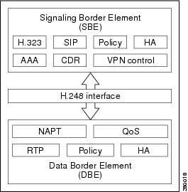
The SBC functions break down into two logically distinct areas:
•![]() The signaling border element (SBE) function. SBEs may support functions that include interworking between various signaling protocols such as H.323 and Session Initiation Protocol (SIP), call admission control, advanced routing policy management, network attack detection, or call billing using RADIUS or DIAMETER. As part of the call admission control function, an SBE informs the data border element (DBE) of the various quality of service (QoS) and Network Address and Port Translation (NAPT) requirements for the call. An SBE typically controls one or more media gateways.
The signaling border element (SBE) function. SBEs may support functions that include interworking between various signaling protocols such as H.323 and Session Initiation Protocol (SIP), call admission control, advanced routing policy management, network attack detection, or call billing using RADIUS or DIAMETER. As part of the call admission control function, an SBE informs the data border element (DBE) of the various quality of service (QoS) and Network Address and Port Translation (NAPT) requirements for the call. An SBE typically controls one or more media gateways.
An SBE may be known as a media gateway controller (MGC).
•![]() The data border element (DBE) controls access of media packets to the network, provides differentiated services and quality of service (QoS) for different media streams, and prevents service theft. The DBE consists of a set of data path functions and responds to the requests made by the SBE to open pinholes, taking into account the specified Network Address Translation (NAT)/firewall traversal and QoS requirements.
The data border element (DBE) controls access of media packets to the network, provides differentiated services and quality of service (QoS) for different media streams, and prevents service theft. The DBE consists of a set of data path functions and responds to the requests made by the SBE to open pinholes, taking into account the specified Network Address Translation (NAT)/firewall traversal and QoS requirements.
The distributed model of the Cisco Unified Border Element (SP Edition) implements the DBE function on the Cisco ASR 1000 Series Aggregation Services Routers. A table of DBE-supported features is listed in Table 1-1.
Figure 1-1 shows an example of SBC high-level architecture; your SBC architecture may differ.
Figure 1-1 Example of SBC High-Level Architecture
Distributed and Unified Models
The SBC can operate in two modes or models—unified and distributed.
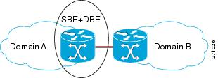
•![]() In the unified model, both the SBE and DBE logical entities co-exist on the same network element.
In the unified model, both the SBE and DBE logical entities co-exist on the same network element.
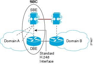
•![]() In the distributed model, the SBE and the DBE entities reside on different network elements. Logically, each of the SBE entities could control multiple DBE elements. The DBE is controlled by one SBE at any one time.
In the distributed model, the SBE and the DBE entities reside on different network elements. Logically, each of the SBE entities could control multiple DBE elements. The DBE is controlled by one SBE at any one time.
Figure 1-2 illustrates the Unified SBC model.
Figure 1-2 Unified SBC Model
Cisco Unified Border Element (SP Edition) can run under the distributed model and provide the DBE functionality.
The distributed model offers advantages over the unified model:
•![]() Scalable to a larger number of sessions.
Scalable to a larger number of sessions.
•![]() Operational advantages, because the SBE can be upgraded or serviced separately from the DBE.
Operational advantages, because the SBE can be upgraded or serviced separately from the DBE.
•![]() The distributed model aligns well with typical voice deployments where the SBE can be co-located with part of the call agent.
The distributed model aligns well with typical voice deployments where the SBE can be co-located with part of the call agent.
•![]() The many-to-many interface offers capability to load share and balance across networks. Operators have the flexibility to optimize on loading of the SBE or DBE.
The many-to-many interface offers capability to load share and balance across networks. Operators have the flexibility to optimize on loading of the SBE or DBE.
Figure 1-3 illustrates the Distributed SBC model.
Figure 1-3 Distributed SBC Model
Supported Features on the Cisco Unified Border Element (SP Edition) Distributed Model
The supported features roadmap lists the features documented in this guide and provides links to where they are documented. Any related configuration commands for a feature are listed and documented in Cisco Unified Border Element (SP Edition) Command Reference: Distributed Model at:
http://www.cisco.com/en/US/docs/ios/sbc/command/reference/sbc_book.html

Note ![]() Table 1-1 lists only the Cisco IOS XE software releases that introduced support for a given feature in a given Cisco IOS XE software release train. Unless noted otherwise, subsequent releases of that Cisco IOS XE software release train also support that feature.
Table 1-1 lists only the Cisco IOS XE software releases that introduced support for a given feature in a given Cisco IOS XE software release train. Unless noted otherwise, subsequent releases of that Cisco IOS XE software release train also support that feature.
Table 1-1 lists features and associated commands that are supported on the Cisco Unified Border Element (SP Edition) DBE deployment on the Cisco ASR 1000 Series Routers.
|
|
|
|
|
|---|---|---|---|
Cisco IOS XE Release 2.1 |
None. |
||
Cisco IOS XE Release 2.1 |
None. |
||
Cisco IOS XE Release 2.1 |
None. |
||
Cisco IOS XE Release 2.1 |
None. |
||
Cisco IOS XE Release 2.1 |
DTMF Interworking on the Cisco Unified Border Element (SP Edition) Distributed Model |
dtmf-duration |
Chapter 3 "DTMF Interworking on the Cisco Unified Border Element (SP Edition) Distributed Model" |
Cisco IOS XE Release 2.1 |
package |
||
Cisco IOS XE Release 2.1 |
h248-association-timeout h248-event-storage h248-preserve-gates |
||
Cisco IOS XE Release 2.1 |
None. |
||
Cisco IOS XE Release 2.1 |
None. |
||
Cisco IOS XE Release 2.1 |
None. |
Chapter 9 "Security in Cisco Unified Border Element (SP Edition) Distributed Model" |
|
Cisco IOS XE Release 2.1 |
None. |
||
Cisco IOS XE Release 2.1 |
None. |
Chapter 9 "Security in Cisco Unified Border Element (SP Edition) Distributed Model" |
|
Cisco IOS XE Release 2.1 |
None. |
||
Cisco IOS XE Release 2.1 |
H.248 Network Package Quality Alert Event and Middlebox Pinhole Timer Expired Event |
h248-media-alert-event |
|
Cisco IOS XE Release 2.1 |
package segment max-pdu-size package segment seg-timer-value show sbc dbe controllers |
||
Cisco IOS XE Release 2.1 |
None. |
||
Cisco IOS XE Release 2.1 |
show sbc dbe media-flow-stats show sbc dbe signaling-flow-stats |
||
Cisco IOS XE Release 2.1 |
None. |
||
Cisco IOS XE Release 2.1 |
show sbc dbe media-flow-stats show sbc dbe signaling-flow-stats |
||
Cisco IOS XE Release 2.1 |
h248-version |
||
Cisco IOS XE Release 2.1 |
None. |
||
Cisco IOS XE Release 2.1 |
Interim Authentication Header Support |
transport (see interim-auth-header keyword) |
Superseded by Interim Authentication Header Full Support |
Cisco IOS XE Release 2.1 |
h248-napt-package |
Chapter 9 "Security in Cisco Unified Border Element (SP Edition) Distributed Model" |
|
Cisco IOS XE Release 2.1 |
None. |
||
Cisco IOS XE Release 2.1 |
None. |
||
Cisco IOS XE Release 2.1 |
ipv6 address (session border controller) media-address ipv6 media-address pool ipv6 port-range (ipv6) debug sbc filter (see ipv6 keyword) show sbc dbe media-flow-stats (see ipv6 keyword) show sbc dbe signaling-flow-stats (see ipv6 keyword) |
||
Cisco IOS XE Release 2.1 |
None. |
Chapter 9 "Security in Cisco Unified Border Element (SP Edition) Distributed Model" |
|
Cisco IOS XE Release 2.1 |
None. |
||
Cisco IOS XE Release 2.1 |
Logging Level feature in Configuring the H.248 Logging Level |
logging level logging filter control protocol |
Chapter 2 "Configuring the Cisco Unified Border Element (SP Edition) Distributed Model" |
Cisco IOS XE Release 2.1 |
media-address pool ipv4 media-address pool ipv6 port-range |
||
Cisco IOS XE Release 2.1 |
None. |
||
Cisco IOS XE Release 2.1 |
None. |
||
Cisco IOS XE Release 2.1 |
None. |
||
Cisco IOS XE Release 2.1 |
None. |
Chapter 9 "Security in Cisco Unified Border Element (SP Edition) Distributed Model" |
|
Cisco IOS XE Release 2.1 |
None. |
||
Cisco IOS XE Release 2.1 |
None. |
||
Cisco IOS XE Release 2.1 |
h248-inactivity-duration |
||
Cisco IOS XE Release 2.1 |
None. |
||
Cisco IOS XE Release 2.1 |
media-address ipv4 media-address pool ipv4 |
Chapter 9 "Security in Cisco Unified Border Element (SP Edition) Distributed Model" |
|
Cisco IOS XE Release 2.1 |
None. |
||
Cisco IOS XE Release 2.1 |
None. |
||
Cisco IOS XE Release 2.1 |
sbc interface-id termination-id rootidname |
||
Cisco IOS XE Release 2.1 |
tmax-timer |
||
Cisco IOS XE Release 2.1 |
None. |
||
Cisco IOS XE Release 2.1 |
transaction-pending functionality |
transaction-pending |
Cisco Unified Border Element (SP Edition) Command Reference: Distributed Model (http://www.cisco.com/en/US/docs/ios/sbc/command/reference/sbc_book.html) |
Cisco IOS XE Release 2.1 |
control-dscp marker-dscp pdr-coefficient show sbc dbe forwarder-stats |
||
Cisco IOS XE Release 2.2 |
None. |
||
Cisco IOS XE Release 2.2 |
H.248 Protocol—Acknowledgment Support for Three-Way Handshake |
None. |
|
Cisco IOS XE Release 2.2 |
None. |
||
Cisco IOS XE Release 2.2 |
transport inbound outbound |
Chapter 9 "Security in Cisco Unified Border Element (SP Edition) Distributed Model" |
|
Cisco IOS XE Release 2.2 |
media-timeout |
||
Cisco IOS XE Release 2.2 |
IPsec Pinhole Support—Twice NAT for IPv4 and No NAT for IPv6 |
media-address ipv4 media-address pool ipv4 media-address ipv6 media-address pool ipv6 |
|
Cisco IOS XE Release 2.3 |
None. |
||
Cisco IOS XE Release 2.3 |
RTCP maximum burst size policing parameter feature in RTCP Policing |
None. |
|
Cisco IOS XE Release 2.6 |
bandwidth-police tman |
||
Cisco IOS XE Release 2.6 |
local-remote-desc always |
||
Cisco IOS XE Release 2.6 |
None. |
||
Cisco IOS XE Release 2.6.2 |
tmax baseroot |
||
Cisco IOS XE Release 3.1S |
h248-profile bandwidth-fields mandatory |
Deployment of the Cisco Unified Border Element (SP Edition) Distributed Model
Deployment of the DBE function on the Cisco ASR 1000 Series Routers integrates a subset of the Cisco Unified Border Element (SP Edition) feature set with Cisco IOS XE software. A likely deployment scenario is that typical routing and broadband features are configured on the Cisco ASR 1000 Series Routers serving as the DBE operating with an external SBE. The Cisco Unified Border Element (SP Edition) functionality on the Cisco ASR 1000 Series Routers comprises both DBE and SBE functions, with DBE being the first to be deployed.
DBE deployment of the Cisco Unified Border Element (SP Edition) feature set is an optional feature supported on the Cisco ASR 1000 Series Routers. DBE deployment on the Cisco ASR 1000 Series Routers does not include SBE support and no SBE-related CLIs are implemented.
In the deployed distributed model, the SBE and the DBE entities reside on different network elements and the DBE is controlled by one SBE at any one time. The SBE interacts with the DBE using the H.248 Megaco (media gateway controller) protocol. The SBE controls the DBE via the H.248 interface. In this model, the bearer (or media flow) always flows through the DBE, and the SBE participates only in the signaling flow.
The DBE is responsible for the media flows and consists of a set of data path functions. The DBE responds to the requests made by the SBE to open pinholes, taking into account the specified NAT/firewall traversal and QoS requirements.
For the DBE, a new interface type is defined for the SBC virtual interface. You configure a virtual interface as part of the SBC configuration and the virtual interface has media IPs as primary or secondary IP addresses. The SBC virtual interface does not support any existing Cisco IOS features.
The Cisco IOS XE image containing Cisco Unified Border Element (SP Edition) software leverages existing Cisco IOS install and packaging facilities for software release, delivery, and installation.
Cisco IOS commands have been introduced to configure the DBE. For information on commands, see Cisco Unified Border Element (SP Edition) Command Reference: Distributed Model at:
http://www.cisco.com/en/US/docs/ios/sbc/command/reference/sbc_book.html
Cisco Unified Border Element (SP Edition) DBE Deployment Scenario
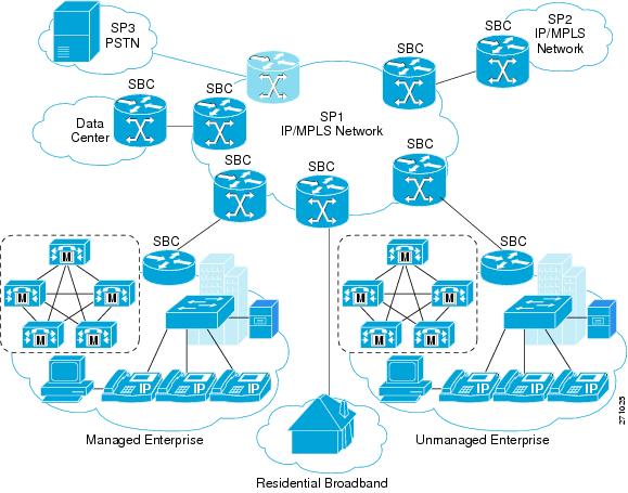
One potential deployment scenario for the distributed model of Cisco Unified Border Element (SP Edition) is in a network architecture where the service provider (SP) provides voice, data, and video services to their residential broadband customers over a single link.
This scenario requires the SP to provide capabilities such as opening pinholes for the duration of a conversation, and doing this without exposing the devices behind the firewall to malicious threats. In addition, given that voice is extremely sensitive to issues such as delay, latency, and packet loss, ensuring adequate performance is a challenge. QoS mechanisms can be implemented to ensure proper priority is assigned to voice packets.
In this deployment scenario, multiple applications share a common link. Thus a mechanism that will limit bandwidth available to individual applications to ensure appropriate end-to-end quality is needed. For voice, this would involve correctly marking the packet to ensure appropriate priority, as well as controlling the number of simultaneous calls at the network entry point. Because the SP cannot dictate what IP phones their customers use, protocol conversion functionality is needed—especially H.323-to-SIP conversion.
Service providers require measurement of traffic for reporting and billing purposes in this potential scenario. Some carriers may also want to offer service level agreement (SLA) for voice, for which they want to be able to provide their customers with the proof that these SLAs are being met.
Figure 1-4 illustrates a deployment where Integrated SBC is used for VoIP interworking.
Figure 1-4 Integrated SBC Used for VoIP Interworking
 Feedback