Introduction to Cisco VG400 Voice Gateway

Cisco medium-density Analog Voice Gateway provide enterprises, managed services providers, and service providers the ability to directly connect public-switched telephone networks (PSTNs) and existing telephony equipment to Cisco 4000 Series Integrated Services Routers. These FXS and FXO ports provide Dual-Tone Multifrequency (DTMF) detection, voice compression and decompression, call progress tone generation, Voice Activity Detection (VAD), echo cancellation, and adaptive jitter buffering. Cisco VG400 Voice Gateway is a medium-density analog voice gateway. It is an intermediate path that enables TDM to IP transition.

The Cisco VG400 Voice Gateway supports the following interfaces:

  • Two RJ45 Gigabit Ethernet (GE) ports

  • One RJ45 Console Port

  • One USB 2.0 Port

  • LED for System, GE Port, and Console Port Status

Features and Benefits of Cisco VG400 Voice Gateway

Cisco VG400 Voice Gateway provides VoIP connectivity to analog devices, such as analog desk phones, analog conference room phones, fax machines, and modems. Cisco 400 Voice Gateway provides several improvements from the previous high-density analog and digital extension modules (EVMs), in the following ways:

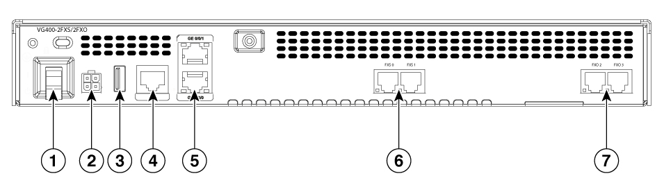
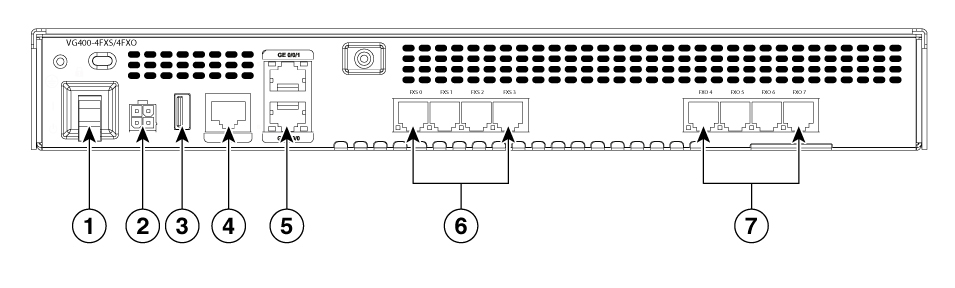
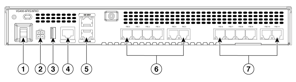
  • On-board Digital Signal Processor (DSP)— The FXO and FXS ports contain an onboard DSP and don’t require the router to have a dedicated packet voice DSP module (PVDM) on the motherboard. The DSP on the voice module is necessary for the voice features. It also provides for echo cancellation of up to 128-ms echo-tail length for demanding network conditions.
  • FXS-E (extended loops) support— FXS ports on the new modules support FXS-E with the following details:
    • Higher loop current (35 mA) to accommodate specialty phones
    • Longer loop length for loops with 26 AWG wire, up to 11,000 feet (3400 meters)
    • Higher ringing voltage (65 Vrms, no load)
  • FXO failover bypass ports— A failover bypass port, also called a failover trunk bypass, provides a way to use designated analog phone ports to make phone calls through the PSTN during a power outage.

In addition to these features, Cisco 400 Voice Gateway also supports the following features:

  • Caller line ID
  • G.711, G.729a, and G.726
  • G722, iLBC, GSMAMR-NB, and Internet Speech Audio Codec (iSAC)
  • Fax detection, pass-through, and relay (T.38)
  • Modem pass-through
  • DTMF detection
  • Echo cancellation
  • Voice activity detection
  • Comfort noise generation
  • Real-Time Control Protocol (RTCP)
  • Acoustic shock protection
  • Real-Time Transport Protocol (RTP)
  • RFC 4733 Digit Relay
  • Noise reduction is on the roadmap

The FXS features include:

  • Support for either FXS or DID functionality
  • Message-Waiting Indicator (MWI)
  • Cable detection: GR909 line test
  • The FXO features include:
  • Support for both ground-start and loop-start modes
  • Support for FXO CAMA signaling type
  • Call Detail Record (CDR) information
  • Support for interworking with Cisco Unified Communications Manager (Skinny Client Control Protocol [SCCP]), H.323, Session Initiation Protocol (SIP), and Media Gateway Control Protocol (MGCP) 0.1
  • Cable detection
  • Overload protection

Analog Phone Connectivity

Cisco 400 Voice Gateway are ideal for analog phone deployments ranging from centralized to sparsely concentrated or distributed topologies. Cisco 400 Voice Gateway offer many supplementary analog calling features, depending on the call control and signaling type used. All supplementary analog features are supported through the FXS and FXO ports. The analog interface on Cisco 400 Voice Gateway also supports Feature Access Codes (FACs) for invoking supplementary services.

Fax and Modem Connectivity

FXS ports on Cisco 450 Voice Gateway support fax machines and modems. When using fax machines, the gateways support T.38 fax relay and fax pass-through. T.38 fax relay technologies allow transfer of faxes across the network with high reliability using less bandwidth than a voice call. All modems can be connected to the Cisco VG Series Gateways and are transferred over the network using modem pass-through.

Protocols Supported

The voice gateways support the following protocols:

  • SCCP
  • H.323v4
  • MGCP
  • SIP
  • Real-Time Transport Protocol (RTP)
  • Secure Real-Time Transport Protocol (SRTP)
  • Trivial File Transfer Protocol (TFTP)
  • HTTP server
  • Simple Network Management Protocol (SNMP)
  • Telnet
  • Dynamic Host Configuration Protocol (DHCP)
  • DNS
  • Cisco Unified Communications Manager or Cisco Unified Communications Manager Express redundancy support using Hot Standby Router Protocol (HSRP)
  • Call survivability: MGCP failover to an H.323 connection to the Survivable Remote Site Telephony (SRST) router
  • T.38 fax relay and modem pass-through
  • Codec support: G.711, G.729. G.729a will be used if the gateway does not support G729 annex b
  • RADIUS and TACACS+ for Telnet and authorization

Cisco VG400 Voice Gateway Chassis

The following figures represent the front and back panels of the Cisco VG400 Voice Gateway chassis:

Cisco VG400 Voice Gateway - front panel

Front panel of the Cisco VG400 Voice Gateway

Cisco VG400 Voice Gateway - back panel

Figure 1. VG400 2FXS/2FXO

Label

Description

1

Power on/off switch

2

12 vdc/7.5A power supply

3

USB support

4

RJ 45 port

5

Gigabit Ethernet ports 0/0/1 and 0/0/0

6

FXS ports

7

FXO ports

Figure 2. VG400 4FXS/4FXO

Label

Description

1

Power on/off switch

2

12 vdc/7.5A power supply

3

USB support

4

RJ 45 port

5

Gigabit Ethernet ports 0/0/1 and 0/0/0

6

FXS ports

7

FXO ports

Figure 3. VG400 6FXS/6FXO

Label

Description

1

Power on/off switch

2

12 vdc/7.5A power supply

3

USB support

4

RJ 45 port

5

Gigabit Ethernet ports 0/0/1 and 0/0/0

6

FXS ports

7

FXO ports

Figure 4. VG400 8FXS
Back panel of the Cisco VG400 Voice Gateway

Label

Description

1

Power on/off switch

2

12 vdc/7.5A power supply

3

USB support

4

RJ 45 port

5

Gigabit Ethernet ports 0/0/1 and 0/0/0

6

FXS ports

LED Indicators

The following table summarizes the LED indicators that are located in the bezel side of Cisco VG400 Voice Gateway:

Table 1.

LED

Represents

Color

Description

PWR

System Power

Green

System power is on and functions correctly

Green blinking

System power is on and in the process of shutting down

Amber

System power is up, but low level initialization has failed

Amber blinking

System power is up, but the system has failed to come out of reset

Off

System power is off

STAT

System Status

Solid Green

System operates normally

Blinking Amber

BIOS/RUMMON booting

Amber

BIOS/ROMMON has completed booting, and system is at the ROMMON prompt or the booting platform software

FLASH

SystemFlash status

Blinking Green

Compact flash/eUSB flash is present and is currently being accessed.

Note Do not remove the flash device while the system is powered on.

FXS/FXO

Voice port status

Green

The voice port is on an active call. That is, in an offhook state.

Off

The voice port is not on an active call. That is, in an idle state or onhook state.

TEMP

Temperature Status

Solid Green

All the temperature sensors in the system are within the acceptable range

Amber

One or more temperature sensors in the system are outside the acceptable range

Off

Temperature is not being monitored

FAN

Fan status

Green

All the fans are operating

Amber

One of the fans has stopped working

Blinking Amber

Two or more fans have stopped working, or the fan tray has been removed

Off

Fans are not monitored

Slot, Bay, and Ports

The FXO port is used to connect to PBX or key systems, or to provide off-premises connections to the PSTN. It supports battery reversal detection and caller ID. The FXO port is also used to connect to analog Centralized Automatic Message Accounting (CAMA) trunks to provide dedicated E-911 service (only in North America).

The FXS port is used to connect analog phones, modems, fax machines, and speaker phones to an enterprise IP voice system, to use them as extensions to your Cisco or third-party IP call-control system. Having these devices tightly integrated with the IP-based phone system is advantageous for increased manageability, scalability, and cost-effectiveness. The Direct Inward Dialing (DID) port is used to provide off-premises DID connection from the central office. It serves only incoming calls from the PSTN. The Caller ID feature is not supported in DID mode.

The following table provides information about Cisco 400 Voice Gateway SKU:

Table 2. Cisco 400 Voice Gateway FXS-E/DID, REN, Failed-over Port Support

Interface

Maximum Number of FXS-E Ports

Maximum Number or RENs

RJ-11 Connectors

Number of Failed-over Ports

VG400-2FXS/2FXO

2

10

FXS: 1x2

FXO: 1x2

2

VG400-4FXS/4FXO

4

12

FXS: 1x4

FXO: 1x4

4

VG400-6FXS/6FXO

6

12

FXS: 1x2 1x4

FXO: 1x2 1x4

6

VG400-8FXS

8

16

FXS: 1x4 1x4

Table 3. Slot, bay, and port information for Cisco VG400 FXS Port

Interface

Slot

Bay

Port

2FXS/2FXO 0/1/0-1

0

1

0-1

4FXS/4FXO 0/1/0-3

0

1

0-3

6FXS/6FXO 0/1/0-5

0

1

0-5

8FXS

0

1

0-7

Table 4. Slot, bay, and port information for Cisco VG400 FXO Port

Interface

Slot

Bay

Port

2FXS/2FXO 0/1/2-3

0

1

2-3

4FXS/4FXO 0/1/4-7

0

1

4-7

6FXS/6FXO 0/1/6-11

0

1

6-11

Technical and Compliance Specifications

The following table details the technical specifications of Cisco VG400 Voice Gateway.

Table 5. Cisco VG400 Voice Gateway Technical Specifications

Feature

VG400-2FXS/2FXO

VG400-4FXS/4FXO

VG400-6FXS/6FXO

VG400-8FXS

Physical

Dimensions (H x W x D)

1.72 x 12.7 x 10" (43.7 x 322.6 x 254 mm)

1.72 x 12.7 x 10" (43.7 x 322.6 x 254 mm)

1.72 x 12.7 x 10" (43.7 x 322.6 x 254 mm)

1.72 x 12.7 x 10" (43.7 x 322.6 x 254 mm)

Weight

6.75 lb (3.06 kg)

6.75 lb (3.06 kg)

6.75 lb (3.06 kg)

6.75 lb (3.06 kg)

Power

AC power

63W

67W

72W

55W

Current

1.5 to 0.6A

1.5 to 0.6A

1.5 to 0.6A

1.5 to 0.6A

Voltage

100 to 240 VAC auto ranging

100 to 240 VAC auto ranging

100 to 240 VAC auto ranging

100 to 240 VAC auto ranging

On-hook voltage

-44V

-44V

-44V

-44V

Off-hook loop current

25 mA (maximum) for short loop-length-port

35 mA for long loop-length-port

25 mA (maximum) for short loop-length-port

35 mA for long loop-length-port

25 mA (maximum) for short loop-length-port

35 mA for long loop-length-port

25 mA (maximum) for short loop-length-port

35 mA for long loop-length-port

Operating temperature

32º to 104ºF (0º to 40ºC)

32º to 104ºF (0º to 40ºC)

32º to 104ºF (0º to 40ºC)

32º to 104ºF (0º to 40ºC)

Non-operating temperature

-40º to 158ºF (-40º to 70ºC)

-40º to 158ºF (-40º to 70ºC)

-40º to 158ºF (-40º to 70ºC)

-40º to 158ºF (-40º to 70ºC)

FXS loop resistance

Up to 600 ohms for short loop-length-port

Up to 1400 ohms for long loop-length-port

Up to 600 ohms for short loop-length-port

Up to 1400 ohms for long loop-length-port

Up to 600 ohms for short loop-length-port

Up to 1400 ohms for long loop-length-port

Up to 600 ohms for short loop-length-port

Up to 1400 ohms for long loop-length-port

DID loop resistance

Up to 1800 ohms (including terminal equipment)

Up to 1800 ohms (including terminal equipment)

Up to 1800 ohms (including terminal equipment)

Up to 1800 ohms (including terminal equipment)

Ringtone

Configurable for different country requirements

Configurable for different country requirements

Configurable for different country requirements

Configurable for different country requirements

Ring voltage

54 Vrms into 5 ringer equivalence numbers (RENs) at zero-loop-length port (balanced) (short-loop-length port)

65 Vrms into 2 RENs at zero-loop-length port (balanced) (long-loop-length port)

54 Vrms into 5 ringer equivalence numbers (RENs) at zero-loop-length port (balanced) (short-loop-length port)

65 Vrms into 2 RENs at zero-loop-length port (balanced) (long-loop-length port)

54 Vrms into 5 ringer equivalence numbers (RENs) at zero-loop-length port (balanced) (short-loop-length port)

65 Vrms into 2 RENs at zero-loop-length port (balanced) (long-loop-length port)

54 Vrms into 5 ringer equivalence numbers (RENs) at zero-loop-length port (balanced) (short-loop-length port)

65 Vrms into 2 RENs at zero-loop-length port (balanced) (long-loop-length port)

Ring frequency

20, 25, 30, and 50 Hz

20, 25, 30, and 50 Hz

20, 25, 30, and 50 Hz

20, 25, 30, and 50 Hz

REN loading

5 RENs per port (short-loop-length port)

2 RENs per port (long-loop-length port)

5 RENs per port (short-loop-length port)

2 RENs per port (long-loop-length port)

5 RENs per port (short-loop-length port)

2 RENs per port (long-loop-length port)

5 RENs per port (short-loop-length port)

2 RENs per port (long-loop-length port)

RJ-11 FXS port terminating impedance option

600c, 600r, 900c, 900r, complex1, complex2, complex3, complex4, complex5, and complex6

600c, 600r, 900c, 900r, complex1, complex2, complex3, complex4, complex5, and complex6

600c, 600r, 900c, 900r, complex1, complex2, complex3, complex4, complex5, and complex6

600c, 600r, 900c, 900r, complex1, complex2, complex3, complex4, complex5, and complex6

Disconnect supervision

Power denial (calling party control and far-end disconnect)

Power denial (calling party control and far-end disconnect)

Power denial (calling party control and far-end disconnect)

Power denial (calling party control and far-end disconnect)

Caller ID

On-hook transmission of frequency-shift-keying (FSK) data

Support for DTMF caller ID

On-hook transmission of frequency-shift-keying (FSK) data

Support for DTMF caller ID

On-hook transmission of frequency-shift-keying (FSK) data

Support for DTMF caller ID

On-hook transmission of frequency-shift-keying (FSK) data

Support for DTMF caller ID

FXS loop length

Short-loop-length port: 3000 ft (900 m) with 26 AWG, 5500 ft (1700 m) with 24 AWG

Long-loop-length port: 11,000 ft (3400 m) with 26 AWG, 18,000 ft (5500 m) with 24 AWG

Short-loop-length port: 3000 ft (900 m) with 26 AWG, 5500 ft (1700 m) with 24 AWG

Long-loop-length port: 11,000 ft (3400 m) with 26 AWG, 18,000 ft (5500 m) with 24 AWG

Short-loop-length port: 3000 ft (900 m) with 26 AWG, 5500 ft (1700 m) with 24 AWG

Long-loop-length port: 11,000 ft (3400 m) with 26 AWG, 18,000 ft (5500 m) with 24 AWG

Short-loop-length port: 3000 ft (900 m) with 26 AWG, 5500 ft (1700 m) with 24 AWG

Long-loop-length port: 11,000 ft (3400 m) with 26 AWG, 18,000 ft (5500 m) with 24 AWG

Ring Waveform

Sine wave if no DC offset

Sine wave if no DC offset

Sine wave if no DC offset

Sine wave if no DC offset

VMWI

FXS ports on VG400 support both FSK and DC voltage VMWI. Default to FSK. (DC voltage VMWI is only supported with STCAPP protocol)

FXS ports on VG400 support both FSK and DC voltage VMWI. Default to FSK. (DC voltage VMWI is only supported with STCAPP protocol)

FXS ports on VG400 support both FSK and DC voltage VMWI. Default to FSK. (DC voltage VMWI is only supported with STCAPP protocol)

FXS ports on VG400 support both FSK and DC voltage VMWI. Default to FSK. (DC voltage VMWI is only supported with STCAPP protocol)

Cables

Category 3 and Category 5

Category 3 and Category 5

Category 3 and Category 5

Category 3 and Category 5

The following table details the compliance specifications of Cisco VG400 Voice Gateway.

Compliance Specification

Description

Safety

  • UL 60950-1
  • CAN/CSA C22.2 No. 60950-1
  • EN 60950-1
  • AS/NZS 60950-1
  • IEC 60950-1

Telecom

  • TIA/EIA/IS-968
  • CS-03
  • TBR21 (FXO)
  • ES 201 970 (FXS)
  • S002, S003
  • Homologation requirements vary by country and interface type. For specific country information, refer to the online approvals data base at: http://www.ciscofax.com.

EMC

  • 47 CFR, Part 15
  • CES-003 Issue 4
  • EN55022 Class A/B
  • CISPR22 Class A/B
  • AS/NZS 3548 Class A
  • VCCI V-3
  • CNS 13438
  • EN 300-386

Immunity

  • EN 55024, CISPR 24
  • EN50082-1
  • EN 61000-6-1
  • EN300-386

Platform and Software Requirements

Cisco 400 Voice Gateway is supported on IOS XE Release16.10.1. The ports provide gateway services for Cisco Unified Communications using Cisco Unified Communications Manager or Cisco Unified Communications Manager Express. The following list provides information about the software version that is compatible with the FXO and FXS ports:.

  • CUCM: 12.5.1, 12.0.1su2 and 12.0.1 (with device pack)

  • IOS XE: Version 16.10.1 and later

Configuration Methods

After Cisco 400 Voice Gateway is operational, use the procedures in Cisco 400 Voice Gateway Software Configuration Guide to configure the specific services and functions or to make changes to an existing configuration.

There are multiple methods for configuring Cisco 400 Voice Gateways:

  • System configuration dialog

  • Configuration mode: Cisco IOS software CLI

  • Setup command facility: Remote configuration through a LAN

  • SNMP-based application: CiscoView or HP OpenView

  • HTTP-based configuration server: Provides access to the CLI from a web browser