Removing and Installing Service Modules
This chapter describes how to remove the SM-1-STM1 service module. This chapter contains the following sections:
•![]() Service Module Removal and Installation
Service Module Removal and Installation
Handling Service Modules
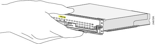
Each service module circuit board is mounted to a metal carrier and is sensitive to electrostatic discharge (ESD) damage.

Note ![]() When a slot is not in use, a blank service module must fill the empty slot to allow the router to conform to electromagnetic interference (EMI) emissions requirements and to allow proper airflow across the service modules. If you plan to install a new service module in a slot that is not in use, you must first remove the blank service module.
When a slot is not in use, a blank service module must fill the empty slot to allow the router to conform to electromagnetic interference (EMI) emissions requirements and to allow proper airflow across the service modules. If you plan to install a new service module in a slot that is not in use, you must first remove the blank service module.

Figure 3-1 Handling a Service Module
Online Insertion and Removal
Note ![]() As you disengage the service module from the router or switch, online insertion and removal (OIR) administratively shuts down all active interfaces in the service module. To properly perform OIR, follow the steps in the following URL:
As you disengage the service module from the router or switch, online insertion and removal (OIR) administratively shuts down all active interfaces in the service module. To properly perform OIR, follow the steps in the following URL:
http://www.cisco.com/en/US/docs/routers/access/2900/hardware/installation/guide/appendix.html#wpxref68698
OIR allows you to install and replace service modules while the system is operating; you do not need to notify the software or reset the system power, although you should not run traffic through the service module you are removing while it is being removed. OIR is a method that is seamless to end users on the network, maintains all routing information, and ensures session preservation.
Note ![]() Before you begin installation, read Chapter 2, "Preparing for Installation," for a list of parts and tools required for installation.
Before you begin installation, read Chapter 2, "Preparing for Installation," for a list of parts and tools required for installation.

Warning ![]() Read the installation instructions before connecting the system to the power source. Statement 1004
Read the installation instructions before connecting the system to the power source. Statement 1004
Warnings and Cautions
Observe the following caution when installing or removing modules:
Equipment Installation Warning
Warning ![]() Only trained and qualified personnel should be allowed to install, replace, or service this equipment. Statement 1030
Only trained and qualified personnel should be allowed to install, replace, or service this equipment. Statement 1030
Warning ![]() Blank faceplates and cover panels serve three important functions: they prevent exposure to hazardous voltages and currents inside the chassis; they contain electromagnetic interference (EMI) that might disrupt other equipment; and they direct the flow of cooling air through the chassis. Do not operate the system unless all cards, faceplates, front covers, and rear covers are in place. Statement 1029
Blank faceplates and cover panels serve three important functions: they prevent exposure to hazardous voltages and currents inside the chassis; they contain electromagnetic interference (EMI) that might disrupt other equipment; and they direct the flow of cooling air through the chassis. Do not operate the system unless all cards, faceplates, front covers, and rear covers are in place. Statement 1029
Warning ![]() Before working on equipment that is connected to power lines, remove jewelry (including rings, necklaces, and watches). Metal objects will heat up when connected to power and ground and can cause serious burns or weld the metal object to the terminals. Statement 43
Before working on equipment that is connected to power lines, remove jewelry (including rings, necklaces, and watches). Metal objects will heat up when connected to power and ground and can cause serious burns or weld the metal object to the terminals. Statement 43
Service Module Removal and Installation
This section describes how to remove and install service modules.
Figure 3-2 Removing the SM-1-STM1 from the Cisco 3945 ISR
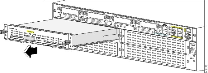
Step 1 ![]() Unscrew the the service module captive screws.
Unscrew the the service module captive screws.
Step 2 ![]() Pull the service module out of the service module slot.
Pull the service module out of the service module slot.
Step 3 ![]() Insert the service module into the service module slot until it is fully seated.
Insert the service module into the service module slot until it is fully seated.
Step 4 ![]() Tighten the captive screws on the service module.
Tighten the captive screws on the service module.
Connecting a SM-1-STM1 Cable
To continue your SM-1-STM1 service module installation, you must connect the interface cables. The instructions that follow apply to all supported platforms.
Note ![]() Optical fiber cables are not available from Cisco Systems; they are available from outside commercial cable vendors. (For more information on the cables you should use with this service module, see the "SM-1-STM1 Optical Fiber Specifications" section on page 1-6 and the "Cables, Connectors, and Pinouts" section on page 1-8.)
Optical fiber cables are not available from Cisco Systems; they are available from outside commercial cable vendors. (For more information on the cables you should use with this service module, see the "SM-1-STM1 Optical Fiber Specifications" section on page 1-6 and the "Cables, Connectors, and Pinouts" section on page 1-8.)
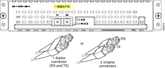
To connect cables to the SM-1-STM1, attach either one duplex optical fiber cable or two simplex optical fiber cables between the SM-1-STM1 interface port and your network. (See Figure 3-3.)
Note ![]() Ensure that you observe the proper relationship of receive (RX) cable to RX SC-type receptacle and transmit (TX) cable to TX SC-type receptacle on the SM-1-STM1.
Ensure that you observe the proper relationship of receive (RX) cable to RX SC-type receptacle and transmit (TX) cable to TX SC-type receptacle on the SM-1-STM1.
Figure 3-3 Connecting Simplex or Duplex Optical Fiber Cables to the SM-1-STM1
Warning ![]() Invisible laser radiation may be emitted from the end of the unterminated fiber cable or connector. Do not view directly with optical instruments. Viewing the laser output with certain optical instruments (for example, eye loupes, magnifiers, and microscopes) within a distance of 100 mm may pose an eye hazard. Statement 1056
Invisible laser radiation may be emitted from the end of the unterminated fiber cable or connector. Do not view directly with optical instruments. Viewing the laser output with certain optical instruments (for example, eye loupes, magnifiers, and microscopes) within a distance of 100 mm may pose an eye hazard. Statement 1056
Warning ![]() Class 1 Laser Product. Statement 1008.
Class 1 Laser Product. Statement 1008.
Warning ![]() Class 1 LED Product. Statement 1027.
Class 1 LED Product. Statement 1027.
 Feedback