Overview of the IR1800 Connecting Process
This chapter describes how to connect the IR1800 to Ground, Power, Ethernet devices and a network.
The documentation set for this product strives to use bias-free language. For the purposes of this documentation set, bias-free is defined as language that does not imply discrimination based on age, disability, gender, racial identity, ethnic identity, sexual orientation, socioeconomic status, and intersectionality. Exceptions may be present in the documentation due to language that is hardcoded in the user interfaces of the product software, language used based on RFP documentation, or language that is used by a referenced third-party product. Learn more about how Cisco is using Inclusive Language.
This chapter contains the following sections:
This chapter describes how to connect the IR1800 to Ground, Power, Ethernet devices and a network.
Before you connect the router to the devices, install the router according to the instructions in Installing the Router.
To prevent damage to your router, turn off the power to the devices and to the router until all connections are completed.
For hazardous location environments, follow these warnings when connecting to destination ports (antenna, serial, Ethernet, and console ports).
 Caution |
Do not turn on the devices until you have completed all the connections to the router. |
To connect a PC (or other Ethernet devices) to an Ethernet switch port, follow these steps.
|
Step 1 |
Connect one end of the Ethernet cable to an Ethernet switch port on the router. |
|
Step 2 |
Connect the other end of the cable to the RJ-45 port on the network interface card (NIC) that is installed in the PC, server, or workstation. |
|
Step 3 |
(Optional) Connect additional servers, PCs, or workstations to the other Ethernet switch ports. |
Connect a PC to the console port either to configure the software by using the CLI, or to troubleshoot problems with the router.
To connect a terminal or PC to the console port on the router and access the CLI, follow these steps:
|
Step 1 |
Connect the Micro-B USB console cable to the console port on the router. |
|
Step 2 |
Connect the opposite end of the micro-USB cable to the USB port on your laptop or PC. |
|
Step 3 |
To communicate with the router, wait for your laptop or PC to discover the new device. |
|
Step 4 |
If your laptop or PC warns you that you do not have the proper drivers to communicate with the router, you can obtain them from your computer manufacturer or from this location: https://www.silabs.com/developers/usb-to-uart-bridge-vcp-drivers |
 Warning |
Statement 1005—Circuit Breaker This product relies on the building’s installation for short-circuit (overcurrent) protection. To reduce risk of electric shock or fire, ensure that the protective device is rated not greater than: 60 VDC minimum, 5A maximum. |
Warning |
Statement 1033—Safety Extra-Low Voltage (SELV)—IEC 60950/ES1–IEC 62368 DC Power Supply To reduce the risk of electric shock, connect the unit only to a DC power source that complies with the SELV requirements in the IEC 60950-based safety standards or the ES1 requirements in the IEC 62368-based safety standards. |
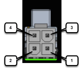
The IR1800 uses a DC power accessory kit (part number PWR-MF4-125W-AC). This needs to be ordered separately. The power entry receptacle is on the IR1800. The pinouts are shown in the following figure.
|
Pin Number |
Name |
Description |
|---|---|---|
|
1 |
DC - |
DC Power Return (GND-) |
|
2 |
CAN_P |
CAN Bus Differential Signal |
|
3 |
DC + |
DC Power Input (12V, 24V) |
|
4 |
CAN_N |
CAN Bus Differential Signal |
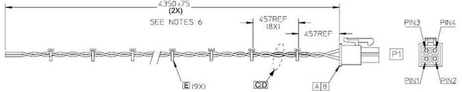
The IR1800 can be installed without connecting to the CAN Bus. There is a 2-wire cable that can be ordered (CAB-PWR-15-MF4). The following is a diagram of the cable:
To verify that all the devices are properly connected to the router, turn on all the connected devices, and then check the LEDs.
 Feedback