Install and Connect the Router

This chapter describes how to install and connect Cisco 900 Series Integrated Services Router (ISR) to LAN and WAN networks.


Warning

Read the installation instructions before using, installing or connecting the system to the power source. Statement 1004


Installing the Cisco 900 Series ISRs involves these tasks:

Unpack the Router

Unpack the router only when you are ready to install it. If the installation site is not ready, to prevent accidental damage, keep the chassis in its shipping container until you are ready to install.

The router, accessory kit, publications, and any optional equipment you order may be shipped in more than one container. When you unpack the containers, check the packing list to ensure that you have received all listed items.

Set up Router on Desktop, Rack, Shelf, or Wall

After unpacking, based on your requirements, you can set up a Cisco 900 Series Integrated Services Routers (ISRs) on a desk or a shelf, under a desk or a shelf, in a rack, or on a wall.

Depending on the model, the available options for mounting a Cisco 900 ISR are:

Table 1. Models and Mounting Options

SKU

Mounting Options

Kit Required

Internal PSU

C921-4P

C921-4PLTENA

C921-4PLTEAS

C921-4PLTEAU

C921-4PLTEGB

C931-4P

On a desk or shelf.

None: Mounting feet are part of the router.

Under a desk or shelf.

Yes: You must order Under-desk kit.

In a rack

Yes: You must order rack-mount-bracket kit.

External PSU

C921J-4P

C926-4P

C926-4PLTEGB

C927-4P

C927-4PM

C927-4PLTEGB

C927-4PMLTEGB

C927-4PLTEAU

On a desk or shelf.

None: Mounting feet are part of the router.

In a rack.

None: You must provide your own tray.

On a wall.

None: You must provide wall-mount hardware.

If you choose to setup the router on a desktop, you can place the router on a desktop, bench top, or shelf.

Rack Mount

Installing the router in a rack requires an optional bracket kit that is not included with the router. You can order these kits from your Cisco representative.


Note

Cisco 900 Series Routers are fanless. When stacking multiple Cisco 900 ISRs, ensure that there is ample surrounding space. Ample space, in turn, ensures more heat removal to enable the surrounding air temperature to stay within the specified operating conditions. A minimum of 1RU space is required above and below the router in the rack for proper ventilation. Refer Figure 1


Attach the Brackets to the Router

This procedure describes how to attach the brackets on the router chassis:

Procedure

Attach a 19-inch bracket to one side of the router using flat-head screw (Refer Figure 2). Follow the same steps to attach the second bracket to the opposite side.

Figure 1. Attaching Brackets to the Cisco ISR 900 Series Router
Figure 2. Flat-head Machine Screws
Figure 3. Router with Bracket Attached to Back Panel
Figure 4. Router with Bracket Attached to Front Panel

Mount the Router

Before mounting the router on to the rack, refer to the following safety warning statements:


Warning

To prevent airflow restriction, allow clearance around the ventilation openings to be at least: 1.75 in. (4.4 cm). Statement 1076.


Warning

To prevent bodily injury when mounting or servicing this unit in a rack, you must take special precautions to ensure that the system remains stable. The following guidelines are provided to ensure your safety:

  • This unit should be mounted at the bottom of the rack if it is the only unit in the rack.

  • When mounting this unit in a partially filled rack, load the rack from the bottom to the top with the heaviest component at the bottom of the rack.

  • If the rack is provided with stabilizing devices, install the stabilizers before mounting or servicing the unit in the rack. Statement 1006.


Procedure

After the brackets are attached to the router, insert the router into the rack, and align the bracket in the rack. Use the machine screws to secure the router in the rack.

Figure 5. Mounting the Cisco ISR 900 Series Router in a Rack
Note 

Allow at least one rack unit (1RU) of vertical space between routers. More clearance may be required when stacking multiple products in the rack that could build up heat in the rack. Ensure that the ambient around the router is within the ambient temperature specified in Table 1.

Note 

The local ambient (not room ambient) is measured below the router.

Routers with external power supply can be mounted in a tray as shown in figure below.

Figure 6. Mounting the Cisco ISR 900 Series Router in a Tray

Wall Mount

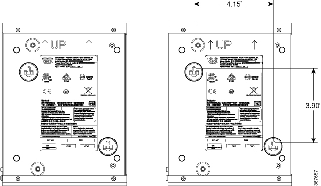
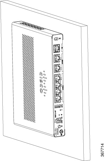
Cisco 900 ISRs designed for wall-mounting (refer Table 1) have mounting holes on the bottom of the chassis for securing with screws or anchors to a vertical surface.


Warning

Read the wall-mounting instructions carefully before beginning installation. Failure to use the correct hardware or to follow the correct procedures could result in a hazardous situation to people and damage to the system. Statement 378


Note

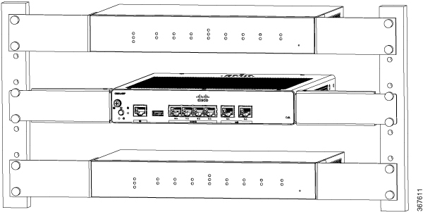
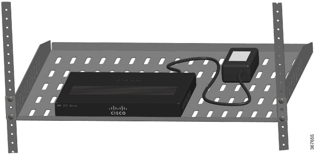
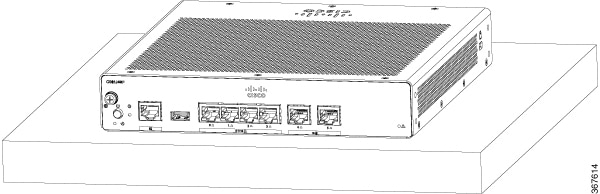
The recommended clearance when a router is horizontally mounted is 1.5 inches on both sides for clearance and 1.75 inches on top. I/O side clearance is needed as it is required to access the cable connections. Clearance is not required on the backside (opposite side from I/O face).


Note

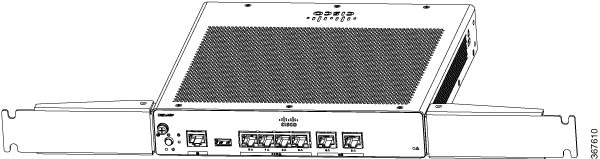
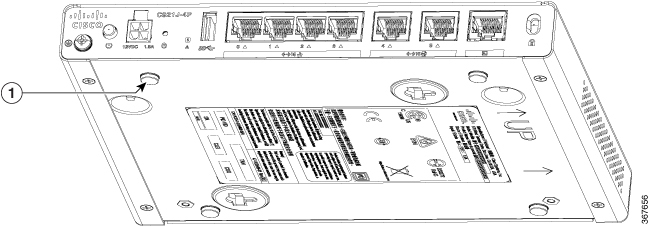
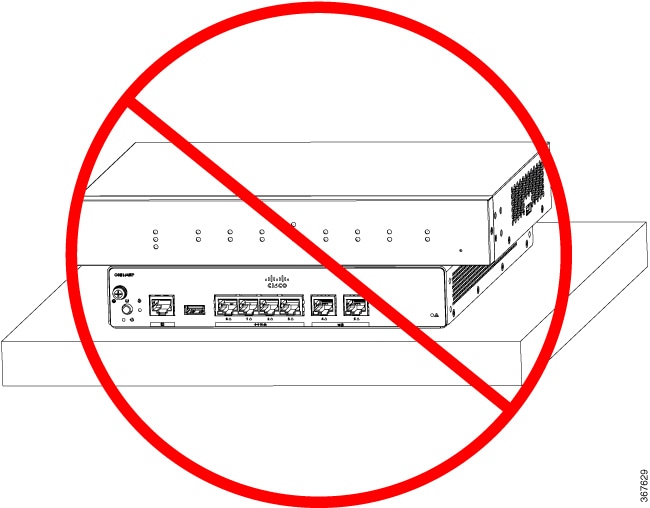
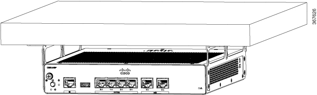
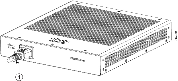
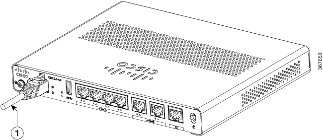
For safety reasons, the only supported wall-mount orientation is as shown in step 3 below. The mounting slots support only this orientation. Marking is provided on the bottom of the router (see step 1) showing the correct orientation.


Note

When choosing a location for wall mounting the router, consider cable limitations and wall structure.


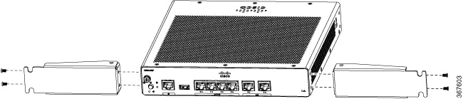
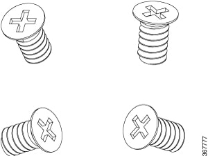
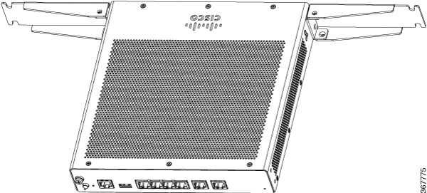
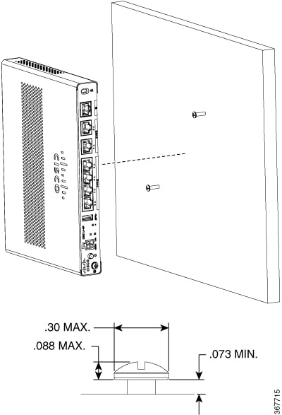
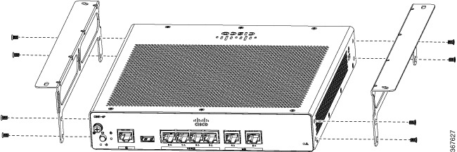
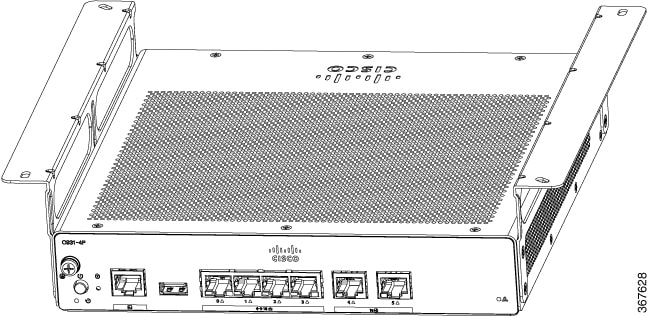
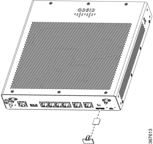
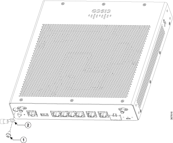
To mount the router on a wall, follow these steps:

Procedure


Step 1

Determine the required distance between mounting holes on the router. For Cisco 900 routers, the distance between mounting holes is 4.15 inches. Figure below shows the wall-mount holes located on the underside of the router.

Figure 7. Router with Wall-mount Holes on the Underside
Step 2

Use a 0.144-inch (3.7 mm) or a #27 drill bit to drill a hole in the wall.

Step 3

Insert the screws, with anchors, into the wall. Leave 1/8 inch (0.32 cm) between the screw head and the wall.

Step 4

Hang the router on the screw without forcibly pushing towards the wall side.


Mount the Router on Desk or Shelf

This procedure describes how to mount router on a desk or a shelf.

Procedure


Place the router on the desk or shelf. At the bottom of the router there are four rubber feet that protect the router and the surface it is on.

Figure 8. Mounting the Cisco ISR 900 Series Router on a Desk or a Shelf
Figure 9. Bottom of the Router with Rubber Feet

1. Rubber Feet (1 of 4)

Note 

Do not stack up routers.


Mount the Router under a Desk or a Shelf

Installing the router under a desk requires an optional bracket kit that is not included with the router. The kit contains the rack-mount brackets and screws to secure the brackets to the router and the underside of the desk. You can order these kits from your Cisco representative. This procedure describes how to mount router under a desk or a shelf .

Procedure


Step 1

Attach a bracket to one side of the router using the flat-head screws (Refer Figure 2). Follow the same steps to attach the second bracket to the opposite side.

Figure 10. Attaching Brackets to the Router
Figure 11. Flat-head Machine Screws
Figure 12. Router with Brackets Attached
Step 2

After the brackets are attached, drill a 2 mm hole under the desk and insert the wooden screws provided. Mount the router under the desk or shelf using the pan-head wood screws (Refer Figure 5 ).

Figure 13. Mounting the Router under a Desk or Shelf
Figure 14. Pan-head Wood Screws

Installing the Micro SIM Card

This section describes how to install and replace the SIM card.


Note

Do not touch any part of the exposed PCB circuit area when the SIM cover is removed.


Note

Make sure that the router is powered off before inserting or removing SIM card.


Procedure


Step 1

Power off the router and disconnect the power cable from the power source.

Step 2

Remove the SIM cover plate by depressing the latch. Use a small flat-head screw-driver to depress the latch.

Figure 15. Installing the SIM card
Step 3

Insert the SIM card by pushing it into the slot. Note that the orientation of the SIM card is important and an icon is shown on the front of the router to assist you.

Step 4

After inserting the SIM card, replace the cover plate.


Chassis Grounding

After you set up the router, connect the chassis to a reliable earth ground; the ground wire must be installed in accordance with local electrical safety standards. For safety information on grounding the chassis, refer to the chassis ground connection procedures.

  1. For grounding the chassis, use size 14 AWG copper wire and the ground lug. These are not a part of the accessory kit.

  2. Use the UNC 6-32 screw provided with the chassis, which have a length of about 0.25 inches.

To install the ground connection for your router, perform these steps:

  1. Strip one end of the ground wire to the length required for the ground lug or terminal.
    • For user-provided ring terminal—as required

  2. Crimp the ground wire to the ground lug or ring terminal, using a crimp tool of the appropriate size.

  3. Attach the ground lug or ring terminal to the chassis as shown in Figure 1. The screw for the ground lug is provided. Tighten the screw; the recommended torque is 8 to 10 inch-lbf (0.9 to 1.1 N-m).

Figure 16. Chassis Ground Connection-Cisco 900

1

Screw (UNC 6-32)

2

Ground Lug

Connect Power Cable

Cisco 900 series routers come with the following power options:

  • Routers with internal AC power supply

  • Routers with external AC power supply

To power the units that come with an internal power supply, plug in the power cord directly to the power socket in the front panel. To power the units that come with an external power supply, plug in the DC power supply to the router's 4-pin power connector in the back panel.

Figure 17. Router with Internal Power Supply

1. Power Cable

Figure 18. Router with External Power Supply

1. Power Cable

Connect the Router to a Console

The Cisco 900 Series ISR has an asynchronous serial port. This port provides administrative access to the router through a console terminal or a PC.

Use the RJ-45 console port on the router to access the Cisco Internet Operating System (IOS) command line interface (CLI) on the router and perform configuration tasks. A terminal emulation program is required to establish communication between the router and a PC.

To configure the router through the Cisco IOS CLI, you must establish a connection between the router console port and either a PC or a terminal.

Use the following cables and adapters to establish a local or remote connection.

Table 2. Local and Remote Connections

Port Type

Cable

Section

Serial (RJ-45)

Cisco 900 ISR: RJ-45 Serial console cable

Connecting to the Serial Port with Microsoft Windows

Connect to the Serial Port with Microsoft Windows

To establish a physical connectivity between the router and a PC, you need to install a Microsoft Windows USB.

Use the USB Console cable plugged into the USB serial port to establish this connection.ß

  1. Connect the end of the console cable with the RJ-45 connector to the light blue console port on the router.

  2. Connect the end of the cable with the DB-9 connector (or USB Type-A) to the terminal or PC. If your terminal or PC has a console port that does not accommodate a DB-9 connector, you must provide an appropriate adapter for that port.

  3. Start a terminal emulator application to communicate with the router. Configure the software with the following parameters:

    • 9600 baud

    • 8 data bits

    • no parity

    • 1 stop bit

    • no flow control

Connect to the Console Port with Mac OS X

This procedure describes how to connect a Mac OS X system USB port to the console using the built in OS X Terminal utility.

Procedure


Step 1

Use the Finder to go to Applications > Utilities > Terminal.

Step 2

Connect the OS X USB port to the router.

Step 3

Enter the following commands to find the OS X USB port number

Example:


macbook:user$ cd /dev
macbook:user$ ls -ltr /dev/*usb*
crw-rw-rw-  1 root    wheel       9,  66 Apr  1 16:46 tty.usbmodem1a21 DT-macbook:dev user$
Step 4

Connect to the USB port with the following command followed by the router USB port speed

Example:


macbook:user$ screen /dev/tty.usbmodem1a21 9600

To disconnect the OS X USB console from the Terminal window

Enter Ctrl-a followed by Ctrl-\


Connect to the Console Port with Linux

This procedure shows how to connect a Linux system USB port to the console using the built in Linux Terminal utility.

Procedure


Step 1

Open the Linux Terminal window.

Step 2

Connect the Linux USB port to the router.

Step 3

Enter the following commands to find the Linux USB port number

Example:


root@usb-suse# cd /dev
root@usb-suse /dev# ls -ltr *ACM*
crw-r--r--    1 root     root     188,   0 Jan 14 18:02 ttyACM0
root@usb-suse /dev#
Step 4

Connect to the USB port with the following command followed by the router USB port speed

Example:


root@usb-suse /dev# screen /dev/ttyACM0 9600

To disconnect the Linux USB console from the Terminal window

Enter Ctrl-a followed by : then quit


Connect WAN and LAN Interfaces

This section describes how to connect WAN and LAN interface cables. Before you connect the interface cables, refer to the following warning statements:


Warning

For connections outside the building where the equipment is installed, the following ports must be connected through an approved network termination unit with integral circuit protection: LAN. Statement 1044.


Warning

Avoid using or servicing any equipment that has outdoor connections during an electrical storm. There may be a risk of electric shock from lightning. Statement 1088.


Ports and Cabling

This section summarizes typical WAN and LAN connections for Cisco 900 Series ISRs. The connections summarized here are described in detail in the Cisco Modular Access Router Cable Specifications document on cisco.com.

Table 3. WAN and LAN Connections

Port or Connection

Port Type, Color1

Connection

Cable

Ethernet

RJ-45, yellow

Ethernet hub or Ethernet switch

Category 5 or higher Ethernet

1 Cable color codes are specific to Cisco cables.

Connection Procedures and Precautions

After you have installed the router chassis, perform these steps to connect the WAN and LAN interfaces:

  • Connect each WAN and LAN to the appropriate connector on the chassis.

  • Position the cables carefully so that you do not strain the connectors.

  • Organize cables in bundles so that cables do not intertwine.

  • Inspect the cables to make sure that the routing and bend radius is satisfactory. If necessary, reposition the cables.

  • Install cable ties in accordance with site requirements.

Configure the Router at Startup

After installing the router and connecting the cables, you can configure the router with basic configurations. For more information on how to configure the router, see the Cisco 900 Series Software Configuration Guide.