About Cisco 900 Series Integrated Service Routers
The Cisco 900 series Integrated Services Routers are the SOHO routers that offer unmatched throughput levels. They are available in fixed form factors. The Cisco 900 series is best suited for small and midsize businesses, enterprise branches and as customer premises equipment in managed services environments.
|
Model |
Switch Ports |
WAN Ports |
Console Ports |
DSL |
|---|---|---|---|---|
|
C921-4P |
4 |
2 |
1 |
None |
|
C921J-4P |
4 |
2 |
1 |
None |
|
C921-4PLTEGB |
4 |
2 |
1 |
None |
|
C921-4PLTEAU |
4 |
2 |
1 |
None |
|
C921-4PLTEAS |
4 |
2 |
1 |
None |
|
C921-4PLTENA |
4 |
2 |
1 |
None |
|
C926-4P |
4 |
1 |
1 |
1 |
|
C926-4PLTEGB |
4 |
1 |
1 |
1 |
|
C927-4P |
4 |
1 |
1 |
1 |
|
C927-4PM |
4 |
1 |
1 |
1 |
|
C927-4PLTEGB |
4 |
1 |
1 |
1 |
|
C927-4PMLTEGB |
4 |
1 |
1 |
1 |
|
C927-4PLTEAU |
4 |
1 |
1 |
1 |
|
C931-4P |
4 |
2 |
1 |
None |
For more information on the features and specifications of Cisco 900 Series Integrated Services Routers (ISRs), refer to the Cisco 900 Series Integrated Services Routers datasheet.
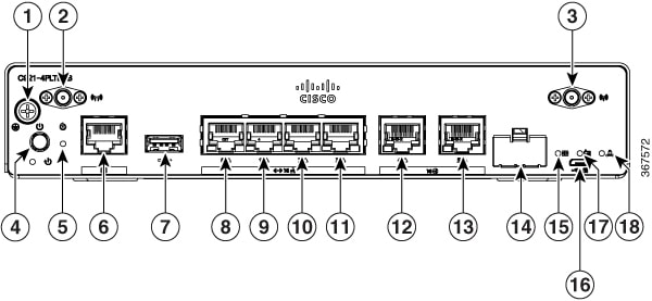
Chassis Views
This section contains front and back panel views of the Cisco 900 Series ISR-showing locations of the power and signal interfaces, interface slots, status indicators, and chassis identification labels.
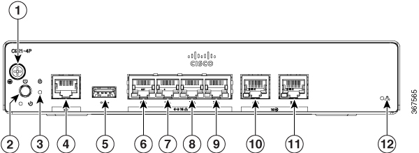
|
1 |
#6-32 Ground screw |
2 |
Power button |
|
3 |
Reset button |
4 |
Console Port |
|
5 |
USB2.0 port |
6 |
GE LAN port |
|
7 |
GE LAN port |
8 |
GE LAN port |
|
9 |
GE LAN port |
10 |
GE WAN port |
|
11 |
GE WAN port |
12 |
VPN LED |
|
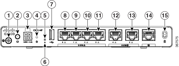
1 |
#6-32 Ground screw |
2 |
Power button |
|
3 |
12VDC input |
4 |
Reset button |
|
5 |
System LED |
6 |
VPN LED |
|
7 |
USB2.0 port |
8 |
GE LAN port |
|
9 |
GE LAN port |
10 |
GE LAN port |
|
11 |
GE LAN port |
12 |
GE WAN port |
|
13 |
GE WAN port |
14 |
Console port |
|
15 |
Kensington Lock |
|
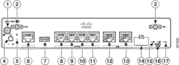
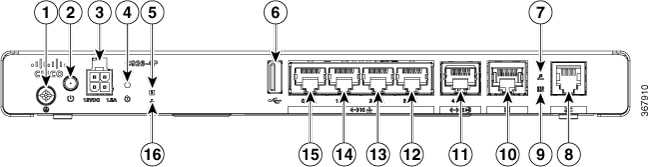
1 |
#6-32 Ground screw |
2 |
4G antenna connector—M1/DIV |
|
3 |
4G antenna connector—M0/MAIN |
4 |
Power button |
|
5 |
Reset button |
6 |
Console port |
|
7 |
USB2.0 port |
8 |
GE LAN port |
|
9 |
GE LAN port |
10 |
GE LAN port |
|
11 |
GE LAN port |
12 |
GE WAN port |
|
13 |
GE WAN port |
14 |
Micro SIM port |
|
15 |
SIM/ACT LED |
16 |
Micro USB port |
|
17 |
VPN LED |
|
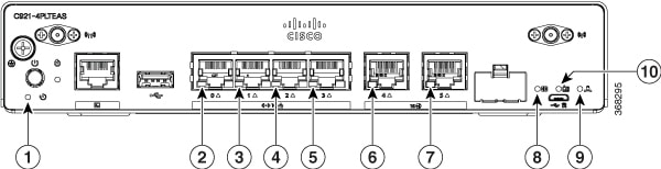
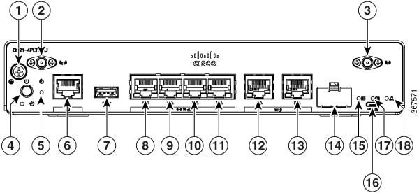
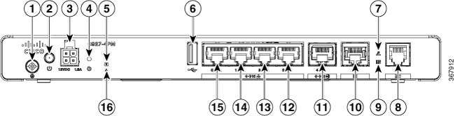
1 |
#6-32 Ground screw |
2 |
4G antenna connector—M1/DIV |
|
3 |
4G antenna connector—M0/MAIN |
4 |
Power button |
|
5 |
Reset button |
6 |
Console port |
|
7 |
USB2.0 port |
8 |
GE LAN port |
|
9 |
GE LAN port |
10 |
GE LAN port |
|
11 |
GE LAN port |
12 |
GE WAN port |
|
13 |
GE WAN port |
14 |
Micro SIM slot |
|
15 |
SIM/ACT LED |
16 |
Micro USB port |
|
17 |
RSSI LED |
18 |
VPN LED |
|
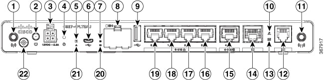
1 |
#6-32 Ground screw |
2 |
Power button |
|
3 |
12VDC input |
4 |
Reset button |
|
5 |
System LED |
6 |
USB2.0 port |
|
7 |
xDSL CD LED |
8 |
DSL port |
|
9 |
xDSL DATA LED |
10 |
Console port |
|
11 |
GE WAN port |
12 |
GE LAN port |
|
13 |
GE LAN port |
14 |
GE LAN port |
|
15 |
GE LAN port |
16 |
VPN LED |

|
1 |
Antenna |
2 |
Power button |
|
3 |
12VDC input |
4 |
Reset button |
|
5 |
System LED |
6 |
Micro USB |
|
7 |
RSSI LED |
8 |
SIM card slot |
|
9 |
USB2.0 port |
10 |
xDSL CD LED |
|
11 |
Antenna |
12 |
DSL port |
|
13 |
xDSL DATA LED |
14 |
Console port |
|
15 |
GE WAN Port |
16 |
GE LAN Port |
|
17 |
GE LAN Port |
18 |
GE LAN Port |
|
19 |
GE LAN Port |
20 |
SIM/ACT LED |
|
21 |
VPN LED |
22 |
#6-32 Ground screw |

|
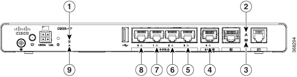
1 |
#6-32 Ground screw |
2 |
Power button |
|
3 |
12VDC input |
4 |
Reset button |
|
5 |
System LED |
6 |
USB2.0 port |
|
7 |
xDSL CD LED |
8 |
DSL port |
|
9 |
xDSL DATA LED |
10 |
Console port |
|
11 |
GE WAN port |
12 |
GE LAN port |
|
13 |
GE LAN port |
14 |
GE LAN port |
|
15 |
GE LAN port |
16 |
VPN LED |
|
1 |
#6-32 Ground screw |
2 |
Power button |
|
3 |
12VDC input |
4 |
Reset button |
|
5 |
System LED |
6 |
USB2.0 port |
|
7 |
xDSL CD LED |
8 |
DSL port |
|
9 |
xDSL DATA LED |
10 |
Console port |
|
11 |
GE WAN port |
12 |
GE LAN port |
|
13 |
GE LAN port |
14 |
GE LAN port |
|
15 |
GE LAN port |
16 |
VPN LED |

|
1 |
Antenna |
2 |
Power button |
|
3 |
12VDC input |
4 |
Reset button |
|
5 |
System LED |
6 |
Micro USB |
|
7 |
RSSI LED |
8 |
SIM card slot |
|
9 |
USB2.0 port |
10 |
xDSL CD LED |
|
11 |
Antenna |
12 |
DSL port |
|
13 |
xDSL DATA LED |
14 |
Console port |
|
15 |
GE WAN Port |
16 |
GE LAN Port |
|
17 |
GE LAN Port |
18 |
GE LAN Port |
|
19 |
GE LAN Port |
20 |
SIM/ACT LED |
|
21 |
VPN LED |
22 |
#6-32 Ground screw |
|
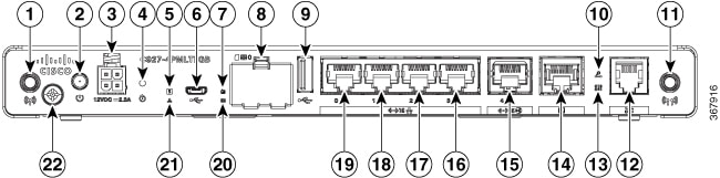
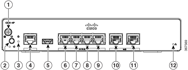
1 |
#6-32 Ground screw |
2 |
Power button |
|
3 |
Reset button |
4 |
Console port |
|
5 |
USB2.0 port |
6 |
GE LAN port |
|
7 |
GE LAN port |
8 |
GE LAN port |
|
9 |
GE LAN port |
10 |
GE WAN port |
|
11 |
GE WAN port |
12 |
VPN LED |
LED Indicators
The following figures and table summarize the LED indicators that are located in the bezel or chassis of the 900 series.
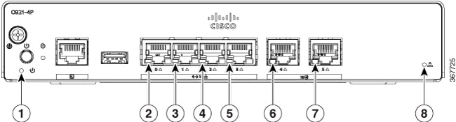
|
1 |
Power LED |
2 |
LAN LED |
|
3 |
LAN LED |
4 |
LAN LED |
|
5 |
LAN LED |
6 |
WAN LED |
|
7 |
WAN LED |
8 |
VPN LED |
|
1 |
System LED |
2 |
xDSL CD LED |
|
3 |
xDSL DATA LED |
4 |
WAN LED |
|
5 |
LAN LED |
6 |
LAN LED |
|
7 |
LAN LED |
8 |
LAN LED |
|
9 |
VPN LED |
|
1 |
Power LED |
2 |
LAN LED |
|
3 |
LAN LED |
4 |
LAN LED |
|
5 |
LAN LED |
6 |
WAN LED |
|
7 |
WAN LED |
8 |
SIM/ACT LED |
|
9 |
VPN LED |
10 |
RSSI LED |
The following table summarizes the LED indicators that are located in the chassis of the Cisco ISR 900 series routers.
|
Port |
LED Color |
Description |
|---|---|---|
|
SYS |
OFF |
System is off |
|
Blink |
Boot up phase or in ROM Monitor mode |
|
|
Steady on |
Normal operation |
|
|
Amber(steady) |
Thermal trip |
|
|
Amber(blink) |
ROMMON code signing verification failure |
|
|
VPN OK |
Green |
At least one VPN session is active |
|
OFF |
VPN not connected |
|
|
LAN |
Green(Solid) |
LAN connection is established. |
| Green (Blinking) |
Data transmission is happening on the link. |
|
|
OFF |
LAN is not connected |
|
|
WAN |
Green(Solid) |
WAN link is established |
|
Green (Blinking) |
Data transmission is happening on the link. |
|
|
OFF |
WAN link is not connected. |
|
|
DSL CD |
OFF |
Shut |
|
Green(Blinking) |
Training, or no shut and cable disconnected. |
|
|
Green (solid) |
Trained |
|
|
DSL Data |
OFF |
Shut |
|
Green(Blinking) |
TX/RX Data |
|
|
RSSI |
Green (Solid) |
Signal > –60 dBm Very strong signal |
|
Yellow |
60dBm > Signal > -75dBm Strong signal |
|
|
Yellow(blinking) |
75dBm > Signal > -90dBm Fair signal |
|
|
OFF |
Signal < –90 dBm Unusable signal |
|
|
SIM |
OFF |
No SIM |
|
Steady on |
SIM present in slot |
|
|
Blink |
TXD/RXD data |
Power Supply
The product power specifications for external power supply units are as follows:
-
AC input voltage: Universal 100 to 240 VAC
-
Frequency: 50 to 60 Hz
-
Maximum output power: 18W or 30W depending on the SKU
-
Output voltage: +12VDC for system power
Specifications of Cisco 900 Series Integrated Services Routers
For specifications on the Cisco 900 Series ISRs, refer to the Cisco 900 series Specifications document.

 Feedback