Connecting the Router

This chapter describes how to connect the Cisco 809 Integrated Services Router to Ethernet devices and a network.

Preventing Damage to the Router

Before installation, observe these general guidelines:

  • Proper ESD protection should be observed.

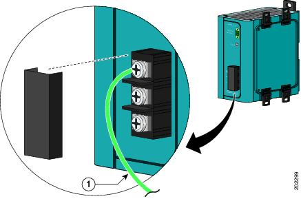
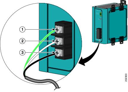
  • Ensure the router is properly grounded.

  • Ensure there is proper airflow around the router.

If you must supply your own cable, see the Technical Specifications for cabling specifications. If this appendix does not provide specifications for a particular cable, we strongly recommend ordering the cable from Cisco.


Warning

The intra-building ports of the equipment or subassembly is suitable for connection to intra-building or unexposed wiring or cabling only. The intra-building port(s) of the equipment or subassembly MUST NOT be metallically connected to interfaces that connect to the OSP or its wiring.These interfaces are designed for use as intra-building interfaces only (Type 2 or Type 4 ports as described in GR-1089-CORE) and require isolation from the exposed OSP cabling. The addition of Primary Protectors is not sufficient protection in order to connect these interfaces metallically to OSP wiring.


Warning

The intra-building ports of the equipment or subassembly must use shielded intra-building cabling/wiring that is grounded at both ends.


Connecting a Terminal or PC to the Console Port

The Cisco 809 ISR does not provide the standard Cisco RJ45 RS232 serial port for Console. Instead, a USB Console port with a mini-Type B connector is provided. Connect a terminal or PC to the Console port either to configure the software by using the CLI or to troubleshoot problems with the router.

To connect a terminal or PC to the Console port on the router and access the CLI, follow these steps:

Before you begin

Before you connect the router to the devices, install the router according to the instructions in Installing the Router.

Procedure


Step 1

Connect the mini-USB side of a cable to the USB Console port on the router. The following figure shows the mini-USB location (1) for the Console port on the router.

Step 2

Connect the opposite end of the mini type B USB cable to the USB port on your laptop or PC.

Step 3

To communicate with the router, wait for your laptop or PC to discover the new device.

Step 4

If your laptop or PC warns you that you do not have the proper drivers to communicate with the router, you can obtain them from your computers manufacturer, or go here: https://www.silabs.com/developers/usb-to-uart-bridge-vcp-drivers

Step 5

Run a Terminal Emulation App (such as Tera Term) from the PC. Select the “standard” serial Com Port (from the standard or enhanced options), and configure it for 9600 Baud rate with no flow control


Connecting to DC Power


Warning

This product relies on the building’s installation for short-circuit (overcurrent) protection. Ensure that the protective device is rated not greater than 10A Statement 1005


Warning

This product requires short-circuit (overcurrent) protection, to be provided as part of the building installation. Install only in accordance with national and local wiring regulations. Statement 1045


Warning

Connect the unit only to DC power source that complies with the safety extra-low voltage (SELV) requirements in IEC 60950 based safety standards. Statement 1033


Caution

The Battery Return (BR) input terminal shall be an isolated DC return (DC-I). The DC return terminal or conductor shall not be connected to the equipment frame, or the grounding means of the equipment.


Plugs and Pin-Outs

The IR809 ships with a DC power accessory kit.

The power entry receptacle is on the IR809. The pin-outs are shown in the following figure.

Figure 1. Power Connector Pin-Outs

Pin Number

Name

Description

Color

1

DC In +

DC Power Positive Input

Red

2

DC In -

DC Power Return

Black

3

AC

Alarm Common

N/A

4

AI

Alarm Input

N/A

Wiring the DC Power and Alarm Connections

To connect the DC power and alarm connections on your Cisco 809 ISR, follow these steps:

Procedure


Step 1

Locate the power and alarm connector on the router front panel.

Note 

Your connector may not have the labels V RT A A.

In the labeled connector, the pins are:

  • V—Positive DC power connection

  • RT— Return DC power connection

  • A— Alarm Common

  • A— Alarm Input

Step 2

Identify the connector positive and return DC power connections.

The connections left to right are:

  • 1—Positive DC power connection

  • 2—Return DC power connection

  • 3—Alarm Common

  • 4—Alarm Input

Step 3

Measure two strands of twisted-pair copper wire (18-to-20 AWG) long enough to connect to the DC power source.

Step 4

Using an 18-gauge wire-stripping tool, strip each of the two twisted pair wires coming from each DC-input power source to 0.25 inch (6.3 mm) ± 0.02 inch (0.5 mm). Do not strip more than 0.27 inch (6.8 mm) of insulation from the wire. Stripping more than the recommended amount of wire can leave exposed wire from the power connector after installation.

Step 5

Remove the two captive screws that attach the power and alarm connector to the router, and remove the connector.

Step 6

On the power and alarm connector, insert the exposed part of the positive wire into the connection labeled "V" and the exposed part of the return wire into the connection labeled "RT". Make sure that you cannot see any wire lead. Only wire with insulation should extend from the connector.

1—Power connector captive screws

Note 

Use the same method for wiring the alarm connections.

Step 7

Use a ratcheting torque flathead screwdriver to torque the power connector captive screws (above the installed wire leads) to 2 in-lb (0.23 N-m).

Step 8

Connect the other end of the positive wire to the positive terminal on the DC power source, and connect the other end of the return wire to the return terminal on the DC power source. Connect the other end of the Alarm wires to your alarm source.


Connecting the Router to the AC-Input Power Supply

A 50 W AC-input power supply is available as an option for the router. The power supply comes in two styles:

  • PWR-IE50W-AC—An AC-input power supply with a terminal block connector for the source AC cable.

  • PWR-IE50W-AC-IEC— An AC-input power supply with an IEC C14 appliance connector for adetachable AC power cord.

The figure below shows the AC-input power supply.

Figure 2. AC-Input Power Supply (PWR-IE50W-AC= Shown)

1

DC out connector

2

STATUS LED

3

Source AC terminal block (Cover shown installed)

Note 

The source AC terminal block shown in the illustration is replaced by an IEC C14 appliance connector on the PWR-50W-AC-IEC= power supply.

Connecting the Router to the DC Source.

To connect the IR809 to the DC output, you will need to use a length of twisted pair along with connectors on both ends. The twisted pair should be sized to handle at least 1 Amp at 24VDC. Details on the connector and pin-outs for the IR809 side are found earlier in this guide at Wiring the DC Power and Alarm Connections. The PWR-IE50W-AC power source comes with a DC clip that can be reused to connect to the IR809. Disassemble the DC clip to expose the 2 pin and 4 pin connectors, as shown in the following diagram.

Dispose of the cover and the wire in the pre-assembled cable clip, but keep the 2-pin connector for the power supply side, and the 4-pin connector for the IR809 side.


Note

The IR809 should already have this 4-pin connector included, but if not, the one in the clip can be used.

Measure an appropriate length of wire for your installation and wire the 2 pin connector back onto the PWR-IE50W-AC power source DC output as it was. Wire the opposite end of the wire to the IR809 4 pin connector as instructed previously in the Wiring the DC Power and Alarm Connections section. Your finished cabling will look like the connectors and wiring in the bottom of the following figure:

The connections should match up as in the following table:

Table 1. DC Source to IR809
PWR-IE50W-AC Pin Number PWR-IE50W-AC Signal Name

Twisted Pair WireDC Power Connectivity

IR809 Pin Number

IR809 Signal Name

1 (Bottom)

Power Out +

—> (Red in Figure)

1 (DC In +)

DC Power Positive Input

2 (Top)

Return Out -

—> (Black in Figure)

2 (DC In -)

DC Power Return

Connecting the Power Converter to an AC Power Source

The following instructions are provided for a qualified electrician to attach the AC power cord to the power supply.


Caution

AC power sources must be dedicated AC branch circuits. Each branch circuit must be protected by a dedicated two-pole circuit breaker.

Caution

Do not insert the power cord into the AC outlet until the process of wiring the line, neutral, and ground connections has been completed.

To connect the AC power cord to the power converter, follow these steps:

Before you begin

To connect the power converter to an AC power source, you need an AC power cord. Power cord connector types and standards vary by country. Power-cord wiring color codes also vary by country. You must to have a qualified electrician select, prepare, and install the appropriate power cord to the power supply.


Note

Use copper conductors only, rated at a minimum temperature of 167°F (75°C).

Procedure


Step 1

Remove the plastic cover from the input power terminals and set it aside.

Figure 3. AC/DC Power Input Terminal Block

1. Ground Wire

Step 2

Insert the exposed ground wire lead into the power converter ground wire connection. Ensure that only wire with insulation extends from the connector.

Figure 4. Connecting AC Power to the Power Converter

1

Ground

2

AC neutral

3

AC line

Step 3

Tighten the ground wire terminal block screw.

The torque should not exceed 2.2 in-lb (0.25 Nm).

Step 4

Insert the line and neutral wire leads into the terminal block line and neutral connections. Make sure that you cannot see any wire lead. Ensure that only wire with insulation extends from the connectors.

Step 5

Tighten the line and neutral terminal block screws.

The torque should not exceed 2.2 in-lb (0.25 Nm).

Step 6

Replace the plastic cover over the terminal block.

Step 7

Connect the other end of the AC power cord to the AC outlet.

Step 8

To apply power to the power converter, move the circuit breaker for the AC outlet or the DC control circuit to the on position.The LED on the power converter front panel is green when the unit is operating normally. The LED is off when the unit is not powered or is not operating normally.


Verifying Connections

To verify that all devices are properly connected to the router, first turn on all the connected devices, then check the LEDs. To verify router operation, refer to the following table.

For full LED description, see LEDs.

Table 2. Verifying the Router Operation

Power and Link

LEDs to Check

Normal Patterns

SYS

Green steady On

Normal operation

Green (blinking)

Boot up phase or in ROM Monitor mode

Amber

Power is OK but possible internal FPGA program failure

GE0 (10/100/1000) WAN 0

GE0 (10/100/1000) WAN 1

Green Steady On

Link is up

Flashing

Transmitting and Receiving data

Off

No link.

SIM cards

SIM0/SIM1

Off—No USIM

Green—USIM installed and active

Cellular Modem

CELLULAR0

Off—Module not powered on

On—Module is powered on and connected but not transmitting or receiving

Slow Blink—Module is powered on and searching for connection

Fast Blink—Module is transmitting or receiving.