The documentation set for this product strives to use bias-free language. For the purposes of this documentation set, bias-free is defined as language that does not imply discrimination based on age, disability, gender, racial identity, ethnic identity, sexual orientation, socioeconomic status, and intersectionality. Exceptions may be present in the documentation due to language that is hardcoded in the user interfaces of the product software, language used based on RFP documentation, or language that is used by a referenced third-party product. Learn more about how Cisco is using Inclusive Language.
This chapter
describes how to install the chassis and includes the following sections:
Prerequisites
Before installing the
chassis, it is important to prepare for the installation by:
Preparing the site (site
planning) and reviewing the installation plans or method of procedures (MOP).
See
Site Planning section.
Unpacking and inspecting the
chassis. See
Chassis-Lifting Guidelines section.
Gathering the tools and test
equipment required to properly install the chassis. See
Tools and Equipment
section.
For more instructions
on how to prepare for the installation of the chassis, see
Preparing for Installation.
Installing the
Chassis in a Rack
Each Cisco NCS 4202
chassis includes the door with Z-rack-mounting brackets. Using the
rack-mounting brackets, you can mount the chassis on the front or rear of the
rack.
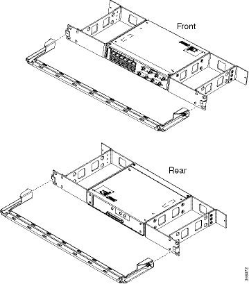
Using the two
rack-mounting brackets for mounting, you can recess the chassis in the
equipment rack. This arrangement provides extra space in front of the chassis
for the cables and allows you to close the doors of racks equipped with
front-close doors.
To attach or replace
the rack-mounting brackets, see the
Installing the Chassis Brackets
section.
The rack-mounting
brackets are slotted to allow the chassis to be mounted in racks with EIA
1.25-inch (3.175-cm) or WECO 1.0-inch (2.54-cm) hole spacing. When installed in
the rack, the chassis requires one EIA 1.75-inch (4.4-cm) vertical mounting
space (or 1 rack unit [RU]) for mounting (see the
Mounting the Chassis in a Rack
section).
Caution
Allow clearance on
either side of the chassis for cooling air to be drawn in through the right
side and circulated through the chassis and out the three-fan exhaust ports
mounted on the other side of chassis.
The following
sections describe how to install the chassis in a rack. The procedures in this
section apply to both horizontal and vertical mounting of the chassis in a
rack:
Installing the
Chassis Brackets
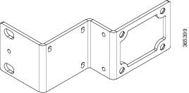
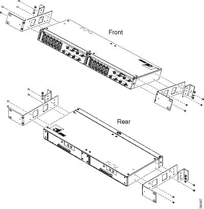
The chassis is
shipped with Z-mounting brackets that can be installed on the front of the
chassis.
Warning
Ensure that you use screws that is provided with the rack mount bracket only. Screw should be secured only with the rack mount
bracket in place.
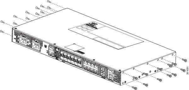
Figure 1. Z Rack Mounting Bracket
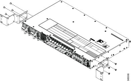
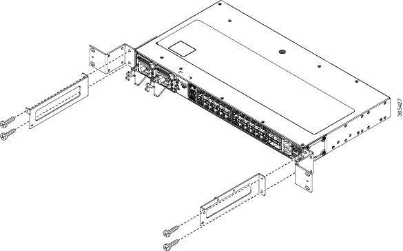
To install the
brackets on the front of the chassis, perform these steps:
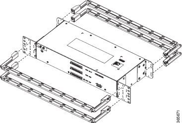
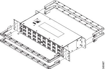
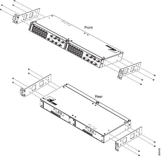
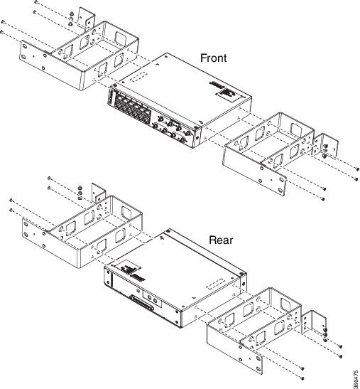
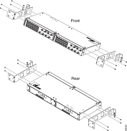
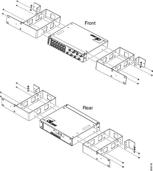
Figure 2. Rack-Mounting Brackets
Mounting the Chassis in a Rack
Perform the steps given below to mount the chassis into the equipment rack.
Note
To secure the chassis to the equipment rack, you must use the two mounting screws (provided) for each side or follow your
local practices for installing the chassis into your equipment rack. Ensure that the rack-mount brackets are securely fastened.
For more information, see the Installing the Chassis Brackets section .
Procedure
Step 1
Locate the equipment rack position where you plan to install the chassis.
Step 2
Verify that there are no obstructions and ensure that the equipment rack is stabilized.
Step 3
Install the chassis brackets. The Rack-mounting brackets figure shows the types of mounting brackets.
Step 4
Locate the mounting holes of the chassis.
Step 5
Align the rack-mounting bracket with the chassis and position with the four #6-32 x 0.25-inch screws (provided).
Step 6
Insert the screws (four places) and tighten using a Number 2 Phillips screwdriver (each side).
Step 7
Position the chassis in the equipment rack lining up the bracket holes on the chassis with the holes on the rack and secure
with four #6-32 x 0.25-inch mounting screws (two on each side).
Step 8
Tighten the screws using a 1/4-inch flat-blade screwdriver (each side). The recommended maximum torque is 10 in.-lb.
Installing the
Chassis in the Rack
Note
Ensure adequate
air flow when mounting the chassis in a rack. For more information, see the
Air Flow Guidelines section.
Note
Install the
cable guides before installing the chassis in a 19-inch EIA rack. See
Attaching the Cable Guides.
To install the
chassis in the equipment rack, perform these steps:
Procedure
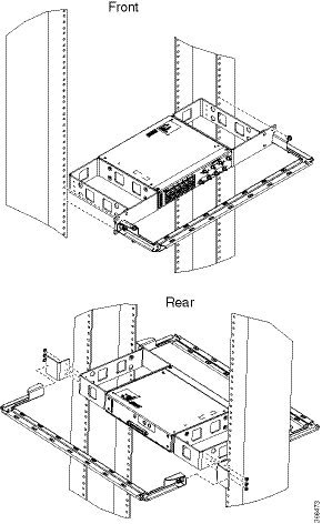
Step 1
Position the
chassis in the rack as follows:
If the front of the chassis
(front panel) is at the front of the rack, insert the rear of the chassis
between the mounting posts.
If the rear of the chassis
is at the front of the rack, insert the front of the chassis between the
mounting posts.
Step 2
Align the
mounting holes in the bracket (and optional cable guide) with the mounting
holes in the equipment rack.
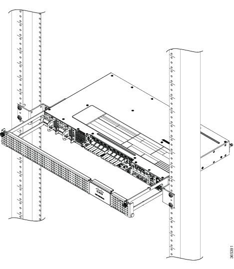
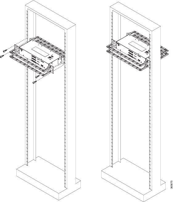
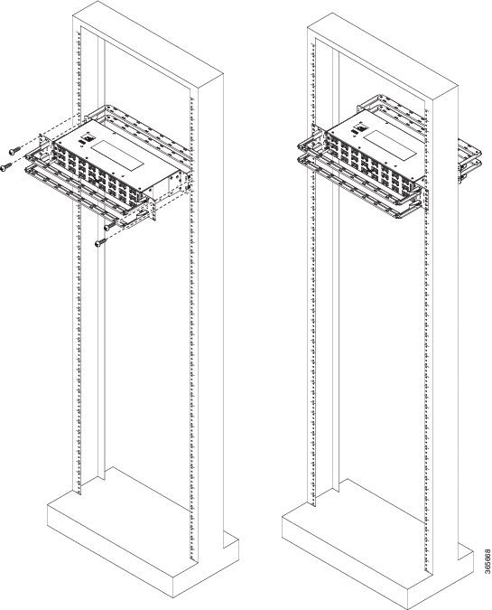
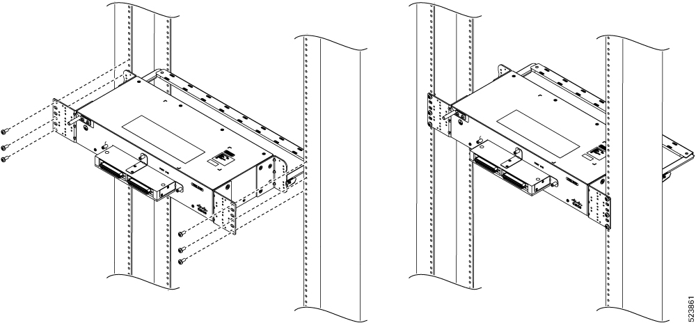
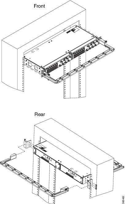
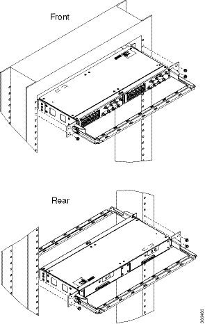
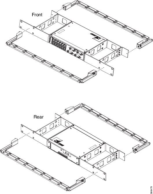
The following
figure shows how to install the chassis in a 19-inch EIA rack.
Figure 3. Installing
the Chassis in the Rack
Step 3
Install the
four M6x12mm zinc-plated steel screws through the holes in the bracket and into
the threaded holes in the equipment rack posts.
Step 4
Use a tape
measure and level to verify that the chassis is installed straight and level.
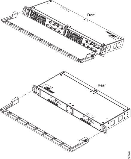
Attaching the Cable Guides
You can guide the cables on the Cisco NCS 4202 through the cable
bracket:
The cable bracket helps in routing the cables from all components on
the front panel thereby enabling a proper cable-bending radius.
To install the
cable guides, perform these steps:
Procedure
Step 1
Position the
cable guide-left and cable guide-right against the front of the chassis and
align the four screw holes, as shown in figure below.
Figure 4. Installing
the Cable Bracket
Figure 5. Guiding
the Cables from the Front Panel through the Cable Brackets
Step 2
Secure the
cable guides with the four M6x12mm screws supplied with the cable kit. The
recommended maximum torque is 3N-m.
Installing and Removing the Front Door
The front door provides additional space in front of the Cisco NCS 4201 to accommodate cables. You can remove the door to
provide unrestricted access to the front of the chassis.
Installing the Front
Door
Procedure
Step 1
Align the door
with the cable bracket as shown in the figure below.
Step 2
Tighten the
screws on both sides on the top and bottom.
Figure 6. Installing the Front Door
Removing the Front
Door
Procedure
The door is
attached to the cable bracket through screws on both sides on the top and
bottom. Loosen the screws on the top left and right corners of the door.
The door falls
outwards, hinged to the cable bracket.
Figure 7. Removing the Front Door
Wall Mounting the Router
To install the router on a wall, follow the instructions in these procedures:
Attaching the
Brackets to the Router for Wall-Mounting
Note
While wall mounting the router, always ensure that the power supplies are at the top position.
The figure below shows
how to attach a 19-inch bracket to one side of the router. Follow the same
steps to attach the second bracket to the opposite side.
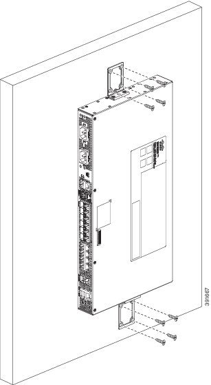
Figure 8. Attaching 19-inch Brackets for Wall Mounting
Mounting the Router on the Wall
For the best support of the router and cables, ensure the router is attached securely to wall studs or to a firmly attached
plywood mounting backboard.
Warning
Suitable for
mounting on and over a concrete or other non-combustible surface only.
Statement 345
Caution
Before mounting the
router, ensure that all unused holes at the sides of the router are always
protected by screws.
Figure 9. Installing Screws in Unused Holes Before Wall Mounting the
Router
Mount the router with the front panel as shown in the following figure.
Figure 10. Mounting the Router on the Wall
Caution
When mounting the router vertically, ensure that the power supplies
are at the top.
Installing and
Removing SFP Modules
These sections
describe how to install and remove SFP modules. The modules are inserted into
the SFP module slots as depicted in Installing an SFP Module into an SFP Module
Slot figure. These field-replaceable modules provide interfaces.
Each port must match
the wavelength specifications on the other end of the cable. For reliable
communications, the cable must not exceed the stipulated cable length.
Use only Cisco SFP
modules on the Cisco chassis. Each SFP module has an internal serial EEPROM
that is encoded with security information. This encoding provides a way for
Cisco to identify and validate that the SFP module meets the requirements for
the chassis.
For detailed
instructions on installing, removing, and cabling the SFP module, see the SFP
module documentation.
Installing SFP
Modules
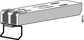
Figure below shows
an SFP module that has a bale-clasp latch.
Caution
We strongly
recommend that you do not install or remove fiber-optic SFP modules with cables
attached because of the potential damage to the cables, the cable connector, or
the optical interfaces in the SFP module. Disconnect all cables before removing
or installing an SFP module. Removing and installing an SFP module can shorten
its useful life. Do not remove and insert SFP modules more often than is
absolutely necessary.
Figure 11. SFP Module with a Bale-Clasp Latch
To insert an SFP
module into the module slot, follow these steps:
Procedure
Step 1
Attach an
ESD-preventive wrist strap to your wrist and to a bare metal surface on the
chassis.
Some SFP
modules identify the top side of the module with send (TX) and receive (RX)
markings or arrows that show the direction of the connection.
Step 2
If the SFP
module that you are using has the markings, use them to identify the top side
of the module.
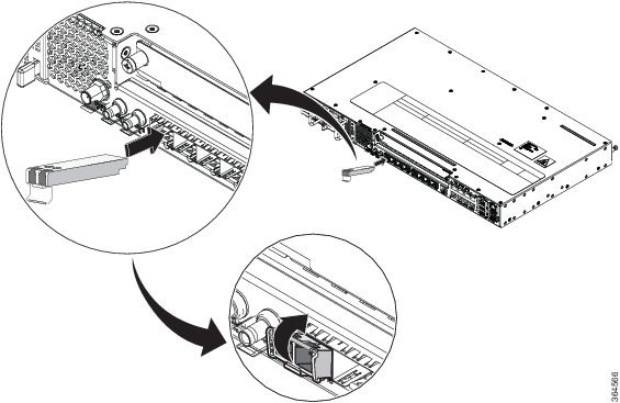
Step 3
Align the SFP
module in front of the slot opening.
Step 4
Insert the SFP
module into the slot until you feel the connector on the module snap into place
in the rear of the slot.
Figure 12. Installing an SFP Module into an SFP Module
Slot
Caution
Do not remove
the dust plugs from the fiber-optic SFP module port or the rubber caps from the
fiber-optic cable until you are ready to connect the cable. The plugs and caps
protect the SFP module ports and cables from contamination and ambient light.
Store the dust plugs for later use.
Step 5
Insert the
cable connector into the SFP module:
For
fiber-optic SFP modules, insert the LC cable into the SFP module.
For copper
1000BASE-T SFP modules, insert the RJ-45 cable connector into the SFP module.
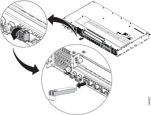
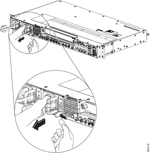
Removing SFP
Modules
To remove an SFP
module from a module receptacle, follow these steps:
Procedure
Step 1
Attach an
ESD-preventive wrist strap to your wrist and to a bare metal surface on the
chassis.
Step 2
Disconnect the
cable from the SFP module, and insert a dust plug into the cable end.
Tip
For
reattachment, note which cable connector plug is send (TX) and which is receive
(RX).
Step 3
Unlock and
remove the SFP module, as shown in the following figure.
If the module
has a bale-clasp latch, pull the bale out and down to eject the module. If the
bale-clasp latch is obstructed and you cannot use your index finger to open it,
use a small, flat-blade screwdriver or other long, narrow instrument to open
the bale-clasp latch.
Figure 13. Removing a Bale-Clasp Latch SFP Module
Step 4
Grasp the SFP
module between your thumb and index finger, and carefully remove it from the
module slot.
Step 5
For fiber-optic
SFP modules, insert a dust plug into the optical ports of the SFP module to
keep the optical interfaces clean.
Step 6
Place the
removed SFP module in an antistatic bag or other protective environment.
Connecting to the Copper Ports
Copper ports [0:7] are capable of working 10/100/1000 Mbps.
Note
The chassis copper ports configure themselves to operate at the
speed of attached devices. If the attached ports do not support
autonegotiation, you can explicitly set the speed and duplex parameters.
Connecting devices that do not autonegotiate or that have their speed and
duplex parameters manually set can reduce performance or result in no linkage.
To maximize performance, choose one of these methods for configuring
the Ethernet ports:
Let the ports
autonegotiate both speed and duplex.
Set the port speed and duplex parameters on both ends of the
connection.
Procedure
Step 1
When connecting to workstations, servers, and chassis, connect a
straight-through cable to an RJ-45 connector on the front panel.When connecting
to chassis or repeaters, use a crossover cable.
Note
You can use the
mdixauto interface configuration command in the
CLI to enable the automatic medium-dependent interface crossover (auto-MDIX)
feature. When the auto-MDIX feature is enabled, the chassis detects the
required cable type for copper Ethernet connections and configures the
interfaces accordingly. Therefore, you can use either a crossover or a
straight-through cable for connections to a copper 100/1000, or an SFP module
port on the chassis, regardless of the type of device on the other end of the
connection.
Step 2
Connect the other end of the cable to an RJ-45 connector on the
other device. The port LED turns on when both the chassis and the connected
device have established link.
If the port LED does not turn on, the device at the other end
might not be turned on, or there might be a cable problem or a problem with the
adapter installed in the attached device.
Note
On user network interface (UNI) ports, the port LED is green
after the link is established.
Step 3
Reconfigure and reboot the connected device, if necessary.
Step 4
Repeat Steps 1 through 3 to connect each device.
Connecting to SFP Modules
This section describes how to connect to SFP modules. For instructions
on how to connect to fiber-optic SFP modules, see the Connecting to Fiber-Optic
SFP Modules.
For instructions about how to install or remove an SFP module, see the
Installing and Removing SFP Modules.
Connecting to
Fiber-Optic SFP Modules
Follow these steps
to connect a fiber-optic cable to an SFP module:
Warning
Invisible laser
radiation may be emitted from disconnected fibers or connectors. Do not stare
into beams or view directly with optical instruments. Statement 1051
Warning
Class 1M laser
radiation when open. Do not view directly with optical instruments. Statement
1053
Warning
Class 1 CDRH) and
Class 1M (IEC) laser products. Statement 1055
Warning
Invisible laser
radiation may be emitted from the end of the unterminated fiber cable or
connector. Do not view directly with optical instruments. Viewing the laser
output with certain optical instruments (for example, eye loupes, magnifiers,
and microscopes) within a distance of 100 mm may pose an eye hazard. Statement
1056
Caution
Do not remove the
rubber plugs from the SFP module port or the rubber caps from the fiber-optic
cable until you are ready to connect the cable. The plugs and caps protect the
SFP module ports and cables from contamination and ambient light.
Procedure
Step 1
Remove the
rubber plugs from the module port and fiber-optic cable, and store them for
future use.
Step 2
Insert one end
of the fiber-optic cable into the SFP module port.
Step 3
Insert the
other cable end into a fiber-optic connector on a target device.
Step 4
Observe the
port status LED.
The LED turns
green when the chassis and the target device have an established link.
If the LED is
off, the target device might not be turned on, there might be a cable problem,
or there might be problem with the adapter installed in the target device.
Step 5
If necessary,
reconfigure and restart the chassis or target device.
Installing the
Chassis Ground Connection
Before you connect
the power or turn on the power to the chassis, you must provide an adequate
chassis ground (earth) connection to your chassis.
This section
describes how to ground the chassis. The grounding lug location is on the back
panel of the chassis.
Tip
Ensure that the
grounding lug wire does not cover the fan opening.
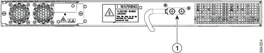
Figure 14. Attaching a Grounding Lug to the Rear of the
chassis
1
Grounding-lug
To ensure that the
chassis ground connection that you provide is adequate, you need the following
parts and tools:
Ratcheting torque screwdriver with Philips head that exerts up to 20 in.-lb (2.25 N-m) of torque for attaching the ground
wire to the Chassis.
Ensure that you secure the lugs only with the Cisco-provided screw or a Philips head screw of 10-32 x 0.37 inch. Secure the
screws only while assembling the lugs.
Crimping tool as specified by the ground lug manufacturer
6-AWG or larger copper wire for the ground wire
Wire-stripping tools appropriate to the wire you are using
Caution
Before making
connections to the chassis, ensure that you disconnect the power at the circuit
breaker. Otherwise, severe injury to you or damage to the chassis may occur.
Caution
Electric Shock
Hazard: This fan tray has to be serviced by trained personnel only.
Warning
This equipment
must be grounded. Never defeat the ground conductor or operate the equipment in
the absence of a suitably installed ground conductor. Contact the appropriate
electrical inspection authority or an electrician if you are uncertain that
suitable grounding is available. Statement 1024
Warning
Use copper
conductors only. Statement 1025
Warning
When installing
the unit, the ground connection must always be made first and disconnected
last. Statement 42
This unit is to be
installed in a restrictive access location and must be permanently grounded to
a minimum 6-AWG copper ground wire.
Perform the
following procedure to ground the chassis using a 2-hole lug and the
corresponding mounting point. Most carriers require a minimum 6-AWG ground
connection. Verify your carrier’s requirements for the ground connection.
Procedure
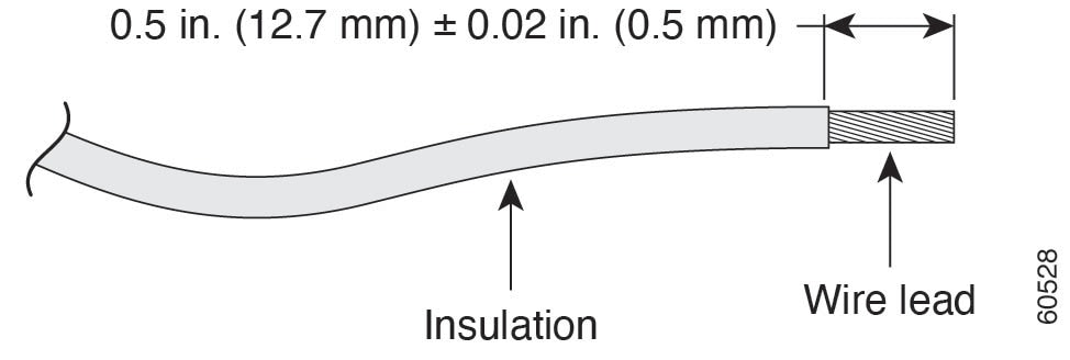
Step 1
If your ground
wire is insulated, use a wire-stripping tool to strip the ground wire to 0.5
inch ± 0.02 inch (12.7 mm ±0.5 mm).
Figure 15. Stripping a Ground Wire
Step 2
Slide the open
end of your 2-hole ground lug over the exposed area of the ground wire.
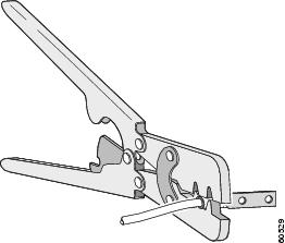
Step 3
Using a
crimping tool (as specified by the ground lug manufacturer), crimp the ground
lug to the ground wire as shown in Figure below.
Figure 16. Crimping a Ground Lug on to the Ground Wire
Step 4
Use a Phillips
head screwdriver to attach the 2-hole ground lug and wire assembly to the
chassis with the 2 pan-head Phillips head screws.
Step 5
Connect the
other end of the ground wire to a suitable grounding point at your site.
Installing and Removing the Fan Tray
This section describes how to install and remove fan trays.
Installing the Fan
Tray
Follow these steps
to install the fan tray in the chassis:
Caution
Electric Shock
Hazard: This fan tray has to be serviced by trained personnel only.
Caution
Always wear the
ESD wrist strap when installing or uninstalling the fan tray.
Caution
Unplug all power
sources before performing this procedure.
Procedure
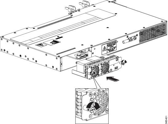
Step 1
Orient the fan
tray so that the captive screws are aligned to the chassis cavity on the back
panel. See below figure.
Step 2
Push the fan
assembly into the chassis until the power connector seats in the backplane and
the captive installation screws make contact with the chassis.
Step 3
Tighten the
captive installation screws, using a flat-blade or number 2 Phillips-head
screwdriver.
Figure 17. Installing the Fan Tray in the Chassis
Removing the Fan
Tray
To remove the
existing fan assembly, follow these steps:
Caution
When removing the
fan tray, keep your hands and fingers away from the spinning fan blades. Let
the fan blades stop completely before you remove the fan tray.
Caution
Unplug all power
sources before performing this procedure.
Caution
Always wear the
ESD wrist strap when installing or uninstalling the fan tray.
Procedure
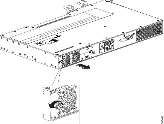
Step 1
Locate the fan
assembly in the chassis. The fan tray is located to the left of the chassis on
the rear side. See below figure.
Step 2
Loosen the two
fan tray captive installation screws by turning them counterclockwise, using a
flat-blade or number 2 Phillips-head screwdriver.
Step 3
Grasp the fan
assembly with both hands, and pull it outward; rock it gently, if necessary, to
unseat the fan assembly power connector from the backplane.
Step 4
Pull the fan
assembly clear of the chassis, and set it aside.
Figure 18. Uninstalling the Fan Tray from the Chassis
Interface Module Installation
The following sections describe the various tasks of associated with interface module installation:
Installing an Interface Module
Caution
Before inserting an interface module, make sure that the chassis is
grounded.
Procedure
Step 1
To insert the interface module, carefully align the edges of the
interface module between the upper and lower edges of the chassis slot.
Step 2
Carefully slide the interface module into the chassis slot until
the interface module makes contact with the backplane.
Step 3
Tighten the locking thumbscrews on both sides of the interface
module. The recommended maximum torque is 5.5 in.-lb (.62 N-m).
Step 4
Connect all the cables to each interface module.
Removing an Interface Module
Procedure
Step 1
To remove an interface module, disconnect all the cables from the
interface module.
Step 2
Loosen the locking thumbscrews on both sides of the interface
module.
Step 3
Slide the interface module out of the chassis slot by pulling on
the handles. If you are removing a blank filler plate, pull the blank filler
plate completely out of the chassis slot using the captive screws.
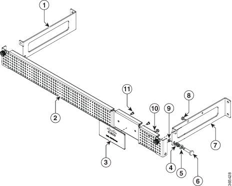
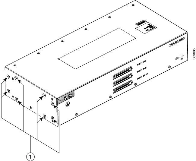
Installing Patch Panel
To install the
brackets on the rear of the patch panel, perform these steps:
Procedure
Step 1
Remove the larger (M4) rack mount screws (as indicated in the Rack Mount Screws figure below) from both sides. To secure the brackets, follow the instructions in Step-3.
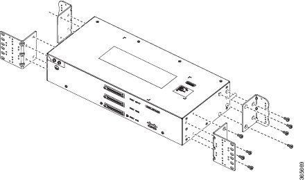
Step 2
Remove the
patch panel rack-mount brackets from the accessory kit and position them beside
the patch panel.
Step 3
Position the brackets against the patch panel sides, and align with the screw holes. Secure the rack mount bracket to patch
panel using a torque of 13.2 in.-lb (1.5 N-m) see the figure below.
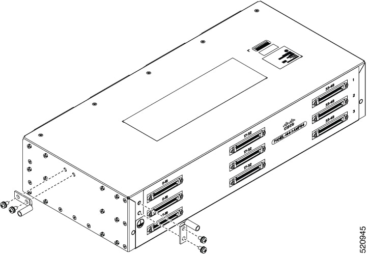
Figure 19. Rack Mount Screws
(1) Rack mount screws to secure rack mount brackets on both the sides.
Figure 20. Patch Panel Front View with Brackets
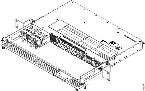
Step 4
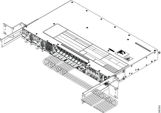
Position the cable management guides against the mounting brackets on the patch panel, see the figure below.
Figure 21. Patch Panel Front View with Brackets and Guides
Figure 22. Patch Panel Rear View with Brackets and Guides
Step 5
Secure the
guides to the brackets with the screws. The recommended maximum torque is 28
in.-lb (3.16 N-m).
Step 6
Position the patch panel with brackets and guide onto the rack and secure with screws provided. The recommended maximum torque
is 28 in.-lb (3.16 N-m), see the figure below.
Note
Cable brackets should be assembled according to the PID used as different
PIDs have different set and quantity of brackets. Refer figures 110 to 115
for PID and cable bracket details.
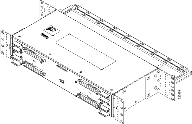
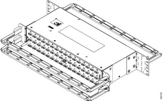
Figure 23. Patch Panel Front View with Brackets and Guides Installed on Rack
Figure 24. Patch Panel Rear View with Brackets and Guides Installed on Rack
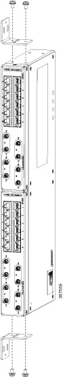
Figure 25. PANEL-16-DIN Patch Panel Mounting Installed on Rack
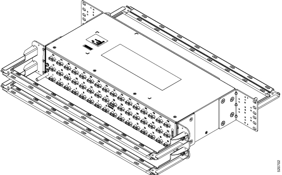
Figure 26. PANEL-48-1-AMP64
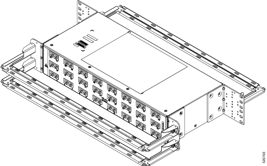
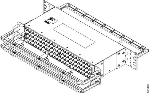
Figure 27. PANEL-48-1-DIN
Figure 28. PANEL-48-1-RJ48
Figure 29. PANEL-48-3-DIN
Note
The installation of PANEL-48-1-AMP64, PANEL-48-1-DIN, PANEL-48-1-RJ48,
and PANEL-48-3-DIN is similar to the installation steps mentioned
above.
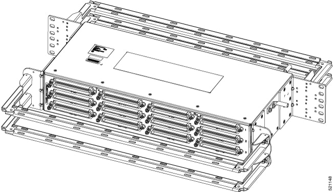
Figure 30. PANEL-48-3-HDBNC
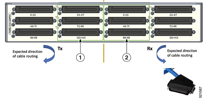
Figure 31. PANEL-144-1-AMP64
Figure 32. Example of 120⁰ Exit Cable Hood
The following table shows details of the 120⁰ exit cable hood:
Table 1. Cable Routing Recommendation for Panel-144-1-AMP64
1
120⁰ exit cable hood with left routing should be used for centre ports on the Tx
side.
2
120⁰ exit cable hood with right routing should be used for centre ports on the Rx
side.
Install 3G Patch Panel
You can choose to either set up the Cisco ASR 903 3G patch panel on a rack or wall mount it.
Install Rack Brackets
Procedure
Step 1
Connect the grounding lugs using a crimping tool (as specified by the ground lug manufacturer), crimp the ground lug to the
ground wire.
Step 2
Use a 6 AWG ground wire to connect the other end to a suitable grounding point at your site.
If the front of the patch panel is at the front of the rack, insert the rear of the chassis between the mounting posts.
If the rear of the patch panel is at the front of the rack, insert the front of the chassis between the mounting posts.
Step 4
Align the mounting holes in the bracket with the mounting holes in the equipment rack.
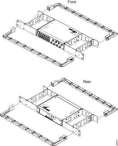
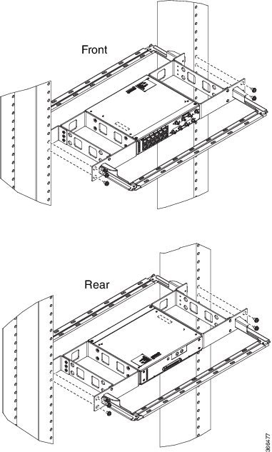
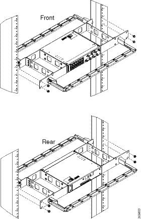
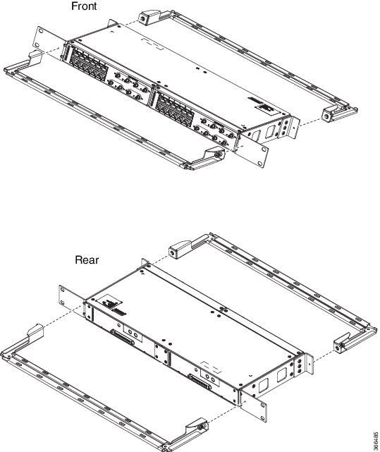
Figure 35. Installing the Patch Panel - Single in a 19-inch Rack
Figure 36. Installing the Patch Panel - Dual in a 19-inch Rack
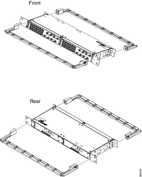
Figure 37. Installing the Patch Panel - Single in a 21-inch Rack
Figure 38. Installing the Patch Panel - Dual in a 21-inch Rack
Figure 39. Installing the Patch Panel - Single in a 23-inch Rack
Figure 40. Installing the Patch Panel - Dual in a 23-inch Rack
Step 5
Secure the brackets to the chassis with the screws. The recommended maximum torque is 28 in.-lb (3.16 N-m).
EIA 19 and 23 inches mounting brackets for both single and double 3G interface module patch panels.
ETSI 21 inches mounting brackets for both single and double 3G interface module patch panels.
Set up 3G Patch Panel on Rack
To install the optional cable management brackets, perform these steps:
Procedure
Step 1
Position the cable management brackets against the front of the chassis and align the screw holes, as shown in the figure.
Step 2
Secure the cable management brackets with the screws. The recommended maximum torque is 10 in.-lb (1.12 N-m).
Figure 41. Attaching 19-inch Brackets to Patch Panel - Single
Figure 42. Installing 19-inch Brackets on to Rack - Single
Figure 43. Attaching 19-inch Brackets to Patch Panel - Dual
Figure 44. Installing 19-inch Brackets on to Rack - Dual
Figure 45. Attaching 21-inch Brackets to Patch Panel - Single
Figure 46. Installing 21-inch Brackets on to Rack - Single
Figure 47. Attaching 21-inch Brackets to Patch Panel - Dual
Figure 48. Installing 21-inch Brackets on to Rack - Dual
Figure 49. Attaching 23-inch Brackets to Patch Panel - Single
Figure 50. Installing 23-inch Brackets on to Rack - Single
Figure 51. Attaching 23-inch Brackets to Patch Panel - Dual
Figure 52. Installing 23-inch Brackets on to Rack - Dual
Wall Mount 3G Patch Panel
Before you begin
You must first install the mounting brackets and cable guides on to the patch panel before you mount it on the wall. You can
use the same rack mount brackets (700-113653-01) for wall mount.
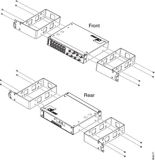
Procedure
Step 1
Remove the mounting brackets from the accessory kit and position them beside the device.
Note
You can install the brackets as shown in the figure.
Figure 53. Wall Mount - Single
Figure 54. Wall Mount - Dual
Step 2
Secure the bracket to the device with the recommended maximum torque of 10 inch-pounds (1.1 newton meters).
Step 3
Position the device vertically on the wall.
Caution
Before mounting the device, ensure that all unused holes at the sides of the device are protected with screws.
Step 4
Use a tape measure and level to verify that the device is installed straight and on level.
Patch Panel Dimensions
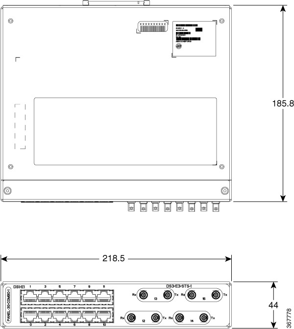
Following are the various patch panel dimensions.
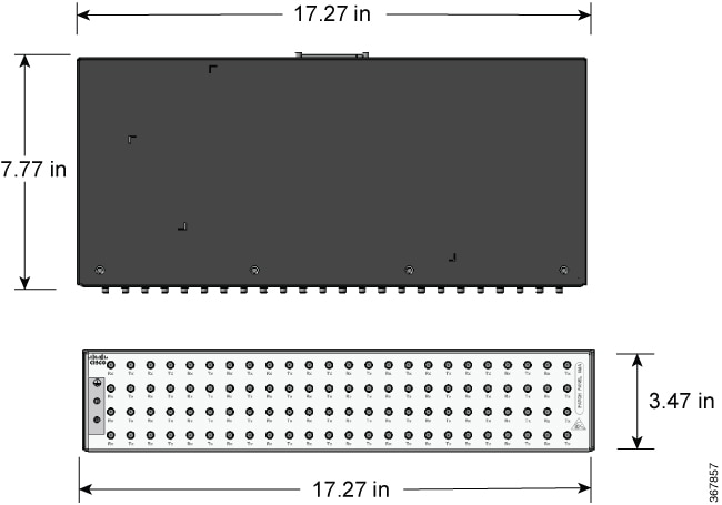
Figure 55. Patch Panel Without Brackets
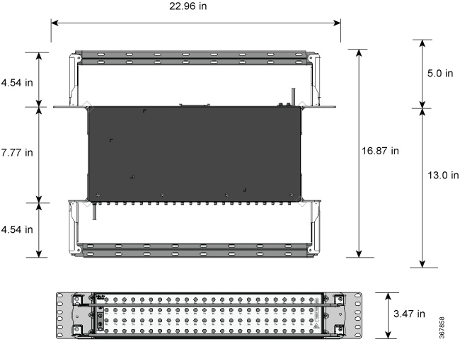
Figure 56. Patch Panel With Brackets
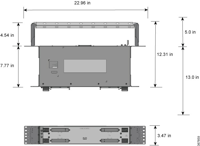
Figure 57. AMP64 Patch Panel With Brackets
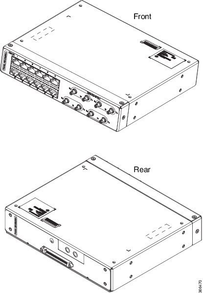
Figure 58. 3G Patch Panel Without Brackets - Single
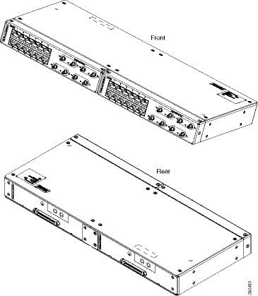
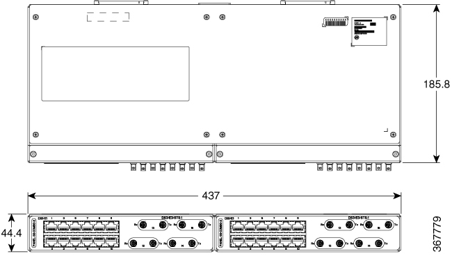
Figure 59. 3G Patch Panel Without Brackets - Dual
Patch Panel Pinout
Given below are the pinout information for the regular crossover and the straight-through cable patch panel.
Table 2. Pinout Details
Pin #
Crossover
Straight-through
1
Receive Tip
Transmit Tip
2
Receive Ring
Transmit Ring
3
—
—
4
Transmit Tip
Receive Tip
5
Transmit Ring
Receive Ring
6
—
—
7
—
—
8
—
—
Panel and Bracket
Table 3. Panel and Bracket Details
Panel
Bracket Description
PANEL-3G-COMBO-1
Single 12E1 + 4xDS3 patch panel for 3G CEM/IMSG IM (requires crossover cable)
PANEL-3G-COMBO-2
Double 12E1 + 4xDS3 patch panel for 3G CEM/IMSG IM (requires crossover cable)
PANEL-3G-COMBO-1S
Single 12E1 + 4xDS3 patch panel for 3G CEM/IMSG (requires a straight-through cable)
PANEL-3G-COMBO-2S
Double 12E1 + 4xDS3 patch panel for 3G CEM/IMSG IM (requires a straight-through cable)
P3G1-RCKMNT-19IN
EIA 19 inches mounting brackets for single 3G CEM/IMSG IM patch panel
P3G1-RCKMNT-ETSI
ETSI 21 inches mounting brackets for single 3G CEM/IMSG IM patch panel
P3G1-RCKMNT-23IN
EIA 23 inches mounting brackets for single 3G CEM/IMSG IM patch panel
P3G2-RCKMNT-19IN
EIA 19 inches mounting brackets for double 3G CEM/IMSG IM patch panel
P3G2-RCKMNT-ETSI
ETSI 21 inches mounting brackets for double 3G CEM/IMSG IM patch panel
P3G2-RCKMNT-23IN
EIA 23 inches mounting brackets for double 3G CEM/IMSG IM patch panel
Installing the Power
Supply
The Cisco NCS 4202
provides the choice of two different power supplies:
DC power—The DC power supply
uses 2-position terminal block-style connector with positive latching/securing
and labeled connections for +24/48V, GRD, -24/48V. The terminal block connector
is of suitable size to carry the appropriate AWG wire size to handle the input
current of the power supply. No ON/OFF switch is provided.
AC power—The AC power supply
has an IEC 320-type power receptacle and a 15 Amp service connector. You can
use standard right angle power cords with the AC power supply. The power supply
includes a power cord retainer. No ON/OFF switch is provided.
You can install dual
power supplies for redundancy.
Warning
Read the
installation instructions before connecting the system to the power source.
Statement 10
Note
Products that have
an AC power connection are required to have an external surge protective device
(SPD) provided as part of the building installation to comply with the
Telcordia GR-1089 NEBS standard for electromagnetic compatibility and safety.
Caution
Do not use
interface module and power supply ejector handles to lift the chassis; using
the handles to lift the chassis can deform or damage the handles.
Power Connection
Guidelines
This section provides
guidelines for connecting the chassis’s power supplies to the site power
source.
Warning
Never defeat the
ground conductor or operate the equipment in the absence of a suitably
installed ground conductor. Contact the appropriate electrical inspection
authority or an electrician if you are uncertain that suitable grounding is
available. Statement 213
Warning
The plug-socket
combination must be accessible at all times because it serves as the main
disconnecting device. Statement 1019
Warning
This product
requires short-circuit (overcurrent) protection, to be provided as part of the
building installation. Install only in accordance with national and local
wiring regulations. Statement 1045
Guidelines for DC-Powered Systems
Basic guidelines for DC-powered systems include the following:
Each chassis power supply
should have its own dedicated input power source. The source must comply with
the safety extra-low voltage (SELV) requirements in the UL 60950, CSA 60950, EN
60950, and IEC 60950 standards.
The circuit must be
protected by a dedicated two-pole circuit breaker. The circuit breaker should
be sized according to the power supply input rating and local or national code
requirements.
The circuit breaker is considered the disconnect device and should
be easily accessible.
The system ground is the power supply and chassis ground.
Do not connect the DC return wire to the system frame or to the
system-grounding equipment.
Use the grounding lug to attach a wrist strap for ESD protection
during servicing.
If the chassis is powered with -48V grounding of the positive, the
it should be done at the power source side and chassis should protected by a
dedicated two-pole circuit breaker.
Guidelines for AC-Powered Systems
Basic guidelines for AC-powered systems include the following:
Each chassis power supply
should have its own dedicated branch circuit.
The circuit breaker should
be sized according to the power supply input rating and local or national code
requirements.
The AC power receptacles
used to plug in the chassis must be the grounding type. The grounding
conductors that connect to the receptacles should connect to protective earth
ground at the service equipment.
Preventing Power
Loss
Use the following
guidelines to prevent power loss to the chassis:
To prevent loss of input
power, ensure that the total maximum load on each circuit supplying the power
supplies is within the current ratings of the wiring and breakers.
In some systems, you can use
an UPS to protect against power failures at your site. Avoid UPS types that use
ferroresonant technology. These UPS types can become unstable with systems such
as the Cisco NCS 4202 Series Chassis, which can have substantial current-draw
fluctuations due to bursty data traffic patterns.
Use the information
in the Cisco NCS 4202 Specifications table to estimate the power requirements
and heat dissipation of the chassis based on a given configuration of the
chassis. Determining power requirements is useful for planning the power
distribution system needed to support the chassis.
Installing the DC
Power Supply Module
Note
This equipment is suitable for installation in Network
Telecommunications Facilities and locations where the NEC applies.
Note
This equipment is suitable for installations utilizing the Common
Bonding Network (CBN).
Note
The grounding
architecture of this product is DC-Isolated (DC-I) for DC-powered products.
DC-powered products have a nominal operating DC voltage of 48 VDC.
Perform the
following procedure to install the power supply module:
Procedure
Step 1
Ensure that the
system (earth) ground connection has been made. See below figure.
Step 2
If necessary,
remove the blank power supply filler plate from the chassis power supply bay
opening by loosening the captive installation screws.
Step 3
Verify that
power to the DC circuit connected to the power supply you are installing is
off. To ensure that power has been removed from the DC circuits, locate the
circuit breakers for the DC circuits, switch the circuit breakers to the OFF
position, and tape the circuit-breaker switches in the OFF position.
Step 4
Grasp the power
supply handle with one hand. Place your other hand underneath the power supply.
Slide the power supply into the power supply bay. Make sure that the power
supply is fully seated in the bay.
Step 5
Tighten the
captive installation screws of the power supply. The recommended maximum torque
is 5.5 in.-lb (0.62 N-m).
Figure 60.
Installing the DC Power Supply Module
Activating a DC
Power Supply Module
Perform the
following procedure to activate a DC power supply:
Procedure
Step 1
Remove the tape
from the circuit-breaker chassis handle, and restore power by moving the
circuit-breaker chassis handle to the On (|) position.
Step 2
Verify power
supply operation by checking if the respective power supply front panel LED
(PS0 or PS1) is green.
Step 3
If the LEDs
indicate a power problem, see
Troubleshooting.
Step 4
If you are
connecting a redundant DC power supply, repeat these steps for the second power
source.
Note
If you are
connecting a redundant DC power supply, ensure that each power supply is
connected to a separate power source in order to prevent power loss in the
event of a power failure.
Installing the DC
Power Cables
Note
When installing
DC power supply, use 14 AWG, 90°C wires. Always ensure that the building’s
installation for short-circuit (overcurrent) protection does not exceed 15A.
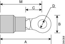
Note
The DC connector
or terminal block has an inbuilt screw and cage nut to which a torque of 1.3 to
1.8 N-m can be applied.
Figure 61. DC Connector With Inbuilt Screw
A
0.97
inches
C
0.27
inches
B
0.31
inches
M
0.81
inches
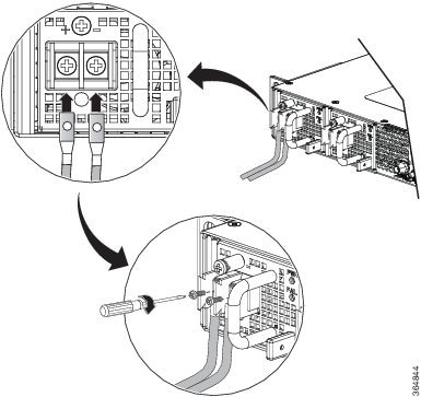
To attach the DC
power supplies:
Procedure
Step 1
Locate the
terminal block plug.
Step 2
Insert the
DC-input power source wires into the terminal block plug.
Step 3
Attach the DC
supply wires using the designated screws.
Step 4
Use a
ratcheting torque screwdriver to torque the terminal block plug captive screw.
See figure below.
Figure 62. Attaching the DC Power Supply Wires
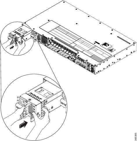
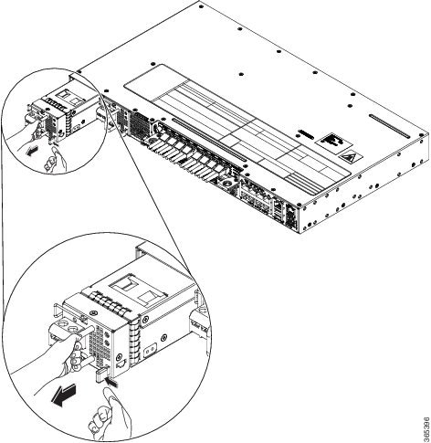
Removing the DC
Power Supply Module
This section
provides information about removing and replacing the DC power supply.
Warning
Before performing
any of the following procedures, ensure that power is removed from the DC
circuit. Statement 1003
Warning
Only trained and
qualified personnel should be allowed to install, replace, or service this
equipment. Statement 1030
Follow these steps
to remove and replace the DC power supply:
Procedure
Step 1
Before
servicing the power supply, switch off the circuit breaker in your equipment
area. As an additional precaution, tape the circuit-breaker switch in the Off
position.
Step 2
Slip on the
ESD-preventive wrist strap that was included in the accessory kit.
Step 3
Switch the
power supply circuit-breaker switch to the Off (O) position.
Step 4
Pull the
terminal block plug connector out of the terminal block head in the power
supply. See figure below.
Step 5
Loosen the
captive screws on the DC power supply.
Step 6
Grasp the power
supply handle. Simultaneously press the power supply lock towards the left and
pull the power supply out from the chassis while supporting it with the other
hand.
Figure 63. Removing
the DC Power Supply Module
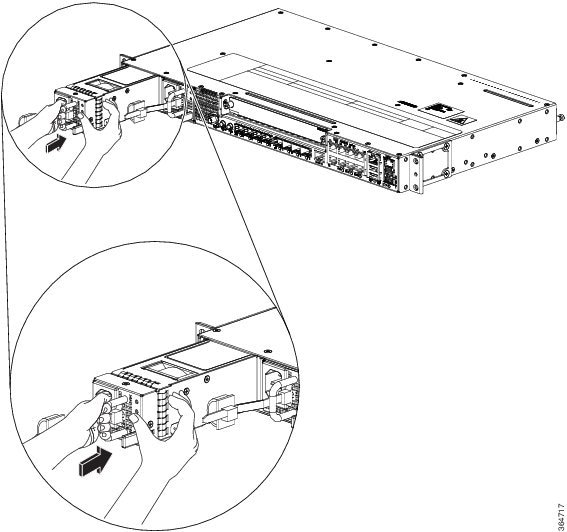
Installing the AC
Power Supply Module
Follow these steps
to install the AC power supply module:
Procedure
Step 1
Ensure that the
system (earth) ground connection has been made.
Step 2
If necessary,
remove the blank power supply filler plate from the chassis power supply bay
opening by loosening the captive installation screws.
Step 3
Grasp the power
supply handle with one hand. Place your other hand underneath the power supply.
Slide the power supply into the power supply bay. Make sure that the power
supply is fully seated in the bay. See below figure.
Figure 64. Installing the AC Power Supply Module
Step 4
Slide the AC
power supply cord inside the tie of the tie-and-holder and tighten the tie
around the power supply cord.
Step 5
Plug the power
supply cord into the AC power supply.
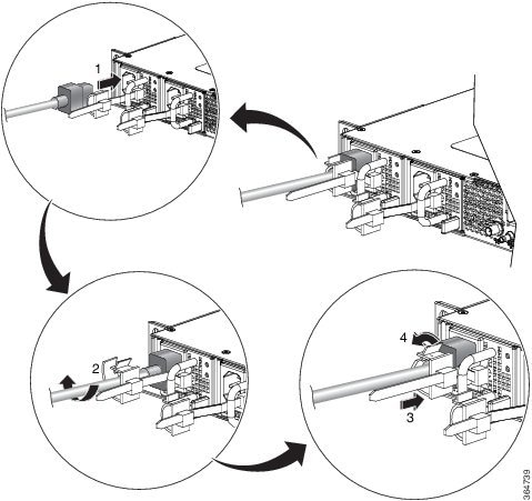
Installing the AC
Power Cables
To install the AC
power cables in the power supply slots:
Procedure
Step 1
Plug the power
supply cord in the power supply module.
Step 2
Insert the
power supply cord into the tie [1] and tighten the tie around the power supply
cord as shown in [2] in the figure below.
Figure 65. Attaching the AC Power Tie-and-Clip Cord
Activating an AC
Power Supply Module
Perform the
following procedure to activate an AC power supply:
Procedure
Step 1
Plug the power
cord into the power supply.
Step 2
Connect the
other end of the power cord to an AC-input power source.
Step 3
Verify power
supply operation by checking if the respective power supply front panel LED
(PS0 or PS1) is green.
Step 4
If the LEDs
indicate a power problem, see
Troubleshooting for troubleshooting information.
Step 5
If you are
connecting a redundant AC power supply, repeat these steps for the second power
source.
Note
If you are
connecting a redundant AC power supply, ensure that each power supply is
connected to a separate power source in order to prevent power loss in the
event of a power failure.
Removing the AC
Power Supply Module
This section
describes how to remove and replace the AC power supply.
Warning
When you install
the unit, the ground connection must always be made first and disconnected
last. Statement 1046
Warning
Only trained and
qualified personnel should be allowed to install, replace, or service this
equipment. Statement 1030
Warning
Installation of
the equipment must comply with local and national electrical codes. Statement
1074
Follow these steps
to remove and replace the AC power supply:
Procedure
Step 1
Disconnect the
power cord from the power source. Do not touch any metal on the power cord when
it is still connected to the power supply.
Step 2
Loosen the tie
and remove the power cord from the tie-and holder.
Step 3
Remove the
power cord from the power connection on the power supply. Do not touch the
metal prongs embedded in the power supply.
Step 4
Grasp the power
supply handle. Simultaneously press the power supply lock towards the left and
pull the power supply out from the chassis while supporting it with the other
hand.
Figure 66. Removing the AC Power Supply Module
Powering On the
Chassis
After the chassis is
either rack mounted or mounted on the wall, perform these tasks to complete the
installation:
Power on the chassis.
Connect the front-panel
ports. See the
Connecting to SFP Modules, to complete the installation.
Connecting the
Chassis to the Network
The following
sections describe how to connect a chassis to the network:
Note
Connect only SELV
services to all the ports.
Connecting Console
Cables
The following
sections describe how to connect to the chassis using console cables:
Connecting to the
USB Serial Port Using Microsoft Windows
This procedure
shows how to connect to the USB serial port using Microsoft Windows.
Note
Install the USB
device driver before establishing a physical connection between the chassis and
the PC, by using the USB console cable plugged into the USB serial port.
Otherwise, the connection will fail. For more information, see the
Installing the Cisco USB Device Driver section.
Procedure
Step 1
Connect a USB
Type A-to-Type A cable to the USB console port, as shown in Removing the AC
Power Supply Module figure. If you are using the USB serial port for the first
time on a Windows-based PC, install the USB driver now according to the
instructions in the following sections:
Note
You cannot
use the USB port and the EIA port concurrently. When the USB port is used, it
takes priority over the EIA port.
Step 2
Connect the USB
Type A cable to the PC.
Step 3
To communicate
with the chassis, start a terminal emulator application, such as Microsoft
Windows HyperTerminal. This software should be configured with the following
parameters:
9600 baud
8 data bits
no parity
1 stop-bit
no flow
control
Connecting to the
Console Port Using Mac OS X
This procedure
describes how to connect a Mac OS X system USB port to the console using the
built-in OS X terminal utility.
Procedure
Step 1
Use the Finder
to choose Applications > Utilities > Terminal.
Step 2
Connect the OS
X USB port to the chassis.
Step 3
Enter the
following commands to find the OS X USB port number:
Example:
macbook:user$ cd /dev
macbook:user$ ls -ltr /dev/*usb*
crw-rw-rw-  1 root    wheel       9,  66 Apr  1 16:46 tty.usbmodem1a21 DT-macbook:dev user$
Step 4
Connect to the
USB port with the following command followed by the chassis USB port speed:
Example:
macbook:user$ screen /dev/tty.usbmodem1a21 9600
To disconnect
the OS X USB console from the terminal window, enter
Ctrl-a followed by
Ctrl-\
Connecting to the
Console Port Using Linux
This procedure
shows how to connect a Linux system USB port to the console using the built-in
Linux terminal utility.
Procedure
Step 1
Open the Linux
terminal window.
Step 2
Connect the
Linux USB port to the chassis.
Step 3
Enter the
following commands to find the Linux USB port number:
Example:
root@usb-suse# cd /dev
root@usb-suse /dev# ls -ltr *ACM*
crw-r--r--    1 root     root     188,   0 Jan 14 18:02 ttyACM0
root@usb-suse /dev#
Step 4
Connect to the
USB port with the following command, followed by the chassis USB port speed:
Example:
root@usb-suse /dev# screen /dev/ttyACM0 9600
To disconnect
the Linux USB console from the terminal window, enterCtrl-a followed by
: then
quit
Installing the Cisco USB Device Driver
A USB device driver must be installed the first time a Microsoft
Windows-based PC is connected to the USB serial port on the chassis.
This procedure describes how to install the Microsoft Windows USB
device driver in Microsoft Windows XP, Windows Vista, Windows 2000, Windows 7,
and Windows 8. Download the driver for your chassis model from the Tools and
Resources Download Software site, USB Console Software category, at:
To download the driver, you must have a valid service contract
associated to your Cisco.com profile.
Procedure
Step 1
Unzip the file asr-9xx_usbconsole_drivers.zip.
Step 2
Double-click xrusbser_ver2100_installer.exe in the
XR21x141x-Win-DriversOnly-Vers2.1.0.0/EXE folder.
Installation Wizard GUI is displayed.
Step 3
Click Next. The InstallShield Wizard Completed window is
displayed.
Step 4
Click Finish.
Step 5
Connect the USB cable to the PC and chassis USB console ports.
Follow the on-screen instructions to complete the installation of the driver.
Step 6
XR21V1401 USB UART Device driver successfully installed message
is displayed.
The USB console is ready for use.
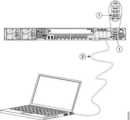
Uninstalling the
Cisco USB Driver
Figure 67. Connecting the USB Console Cable to the Cisco NCS
4202
1
USB
Type-A console port
2
USB
Type-A to USB Type-A console cable
This procedure
describes how to uninstall the Microsoft Windows USB device driver in Microsoft
Windows XP, Windows Vista, Windows 2000, Windows 7, and Windows 8.
Note
Disconnect the
chassis console terminal before uninstalling the driver.
Procedure
Step 1
Choose Start
> Control Panel > Add or Remove Programs.
Step 2
Scroll to
WindowsDriverPackage-Exarcorporation(xrusbser)Ports and click
Remove. The
ProgramMaintenance window is displayed.
Step 3
Click
Yes to
uninstall the driver.
Connecting to the
EIA Console Port
Note
The US-to-RJ45
adapter cable and the DB9 console cable are not included with the chassis; they
can be ordered separately from Cisco.
Note
The serial
console cable kit is not included with the chassis; it is ordered separately.
To connect a
terminal to the EIA Console port on the chassis, follow these steps:
Procedure
Step 1
Connect the USB
end of the USB-to RJ-45 cable to the EIA Console port.
Step 2
Connect the
RJ-45 end of the DB-9 adapter cable to the USB-to RJ-45 cable, as shown in
below figure.
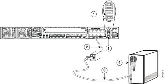
Figure 68. Connecting a Modem to the Cisco NCS 4202 Series
Chassis
Step 3
Connect the
DB-9 end of the console cable to the DB-9 end of the terminal.
Step 4
To communicate
with the chassis, start a terminal emulator application, such as Microsoft
Windows HyperTerminal. This software should be configured with the following
parameters:
Label
Component
Label
Component
1
EIA
Console port
3
RJ-45
to DB-9 cable
2
USB-to-RJ45 adapter
4
Desktop or system
9600 baud
8 data bits
no parity
1 stop-bit
no flow
control
Connecting a Management Ethernet Cable
When using the Ethernet Management port in the default mode (speed-auto
and duplex-auto) the port operates in the auto-MDI/MDI-X mode. The port
automatically provides the correct signal connectivity through the
Auto-MDI/MDI-X feature. The port automatically senses a crossover or
straight-through cable and adapts to it.
However, when the Ethernet Management port is configured to a fixed
speed (10, 100, or 1000 Mbps) through command-line interface (CLI) commands,
the port is forced to the MDI mode.
When in a fixed-speed configuration and MDI mode:
Use a crossover cable to
connect to an MDI port
Use a straight-through
cable to connect to an MDI-X port
Caution
To comply with the Telcordia GR-1089 NEBS standard for
electromagnetic compatibility and safety, connect the Management Ethernet ports
only to intra-building or unexposed wiring or cable. The intrabuilding cable
must be shielded and the shield must be grounded at both ends. The
intra-building port(s) of the equipment or subassembly must not be metallically
connected to interfaces that connect to the OSP or its wiring. These interfaces
are designed for use as intra-building interfaces only (Type 2 or Type 4 ports
as described in GR-1089-CORE) and require isolation from the exposed OSP
cabling. The addition of Primary Protectors is not sufficient protection in
order to connect these interfaces metallically to OSP wiring.
Installing and
Removing SFP and SFP+ Modules
The Cisco NCS 4202
Series Chassis supports a variety of SFP and SFP+ modules, including optical
and Ethernet modules. For information on how to install and remove SFP and SFP+
modules, see the documentation for the SFP or SFP+ module at:
We recommend that
you wait for 30 seconds between the removal and insertion of an SFP on an
interface module. We recommend this to allow the transceiver software to
initialize and synchronize with the Cisco NCS 4202 Series Chassis. Changing an
SFP more quickly could result in transceiver initialization issues that disable
the SFP.
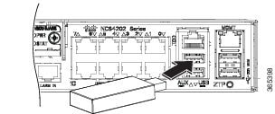
Connecting a USB
Flash Device
To connect a USB
flash device to the chassis, insert the memory stick in the USB port labeled
USB MEM. The Flash memory module can be inserted only one way, and can be
inserted or removed regardless of whether the chassis is powered up or not.
Figure below shows
the USB port connector on the Cisco NCS 4202 Series Chassis.
Figure 69. Flash Token Memory Stick
Removing a USB Flash Device
Note
If the USB flash device is abruptly removed, the constant sync operations of the
file system in progress fail due to the USB device removal. These errors occur
with ext2 or ext3 or ext4 file systems and are not seen with fat32 file system.
This is a default behavior on any Linux platform.
The following error messages are displayed when you remove the USB device:
To remove and replace a USB flash token memory stick from and into a
chassis, follow these steps:
Procedure
Step 1
Pull the memory stick from the USB port.
Step 2
To replace the Cisco USB Flash memory stick, simply insert the
module into the USB port labeled USB MEM. The Flash memory module can be
inserted only one way, and can be inserted or removed regardless of whether the
chassis is powered up or not.
This completes the USB Flash memory installation procedure.
Connecting Timing
Cables
The following
sections describe how to connect timing cables to the Cisco NCS 4202 Series
Chassis:
Connecting Cables to
a GPS Interface
The following
sections describe how to connect cables from the Cisco NCS 4202 to a GPS unit
for input or output timing of frequency:
Connecting a Cable to the Input 10-Mhz or 1-PPS Interface
Procedure
Step 1
Connect one end of a shielded mini-coax cable to the GPS unit.
Step 2
Connect the other end of the shielded mini-coax cable to the
10-Mhz or 1-PPS port on the Cisco NCS 4202 Series Chassis.
Connecting a Cable to the Output 10-Mhz or 1-PPS Interface
Procedure
Step 1
Connect one end of a shielded mini-coax cable to the Slave unit.
Step 2
Connect the other end of the shielded mini-coax cable to the
10-Mhz or 1-PPS port on the Cisco NCS 4202 Series Chassis.
Connecting a Cable
to the ToD Interface
Procedure
Step 1
Connect one end
of a straight-through Ethernet cable to the GPS unit.
Step 2
Connect the
other end of the straight-through Ethernet cable to the ToD or 1-PPS port on
the Cisco NCS 4202 Series Chassis.
What to do next
Note
For instructions on how to configure clocking, see the
Cisco NCS 4200 Series Configuration Guide .
Warning
To comply with the Telcordia GR-1089 NEBS standard for
electromagnetic compatibility and safety, connect the ToD ports only to
intra-building or unexposed wiring or cable. The intrabuilding cable must be
shielded and the shield must be grounded at both ends. The intra-building
port(s) of the equipment or subassembly must not be metallically connected to
interfaces that connect to the OSP or its wiring. These interfaces are designed
for use as intra-building interfaces only (Type 2 or Type 4 ports as described
in GR-1089-CORE) and require isolation from the exposed OSP cabling. The
addition of Primary Protectors is not sufficient protection in order to connect
these interfaces metallically to OSP wiring.
Note
For more information about GPS-port pinouts, see
Troubleshooting.
Connecting Ethernet
Cables
The Cisco NCS 4202
Series Chassis interface modules support RJ-45 and Ethernet SFP ports. For
instructions on how to connect cables to Ethernet SFP ports, see the
Connecting Cables to SFP Modules.
The RJ-45 port
supports standard straight-through and crossover Category 5 unshielded
twisted-pair (UTP) cables. Cisco does not supply Category 5 UTP cables; these
cables are available commercially.
Warning
To comply with
the Telcordia GR-1089 NEBS standard for electromagnetic compatibility and
safety, connect the Gigabit Ethernet ports only to intra-building or unexposed
wiring or cable. The intrabuilding cable must be shielded and the shield must
be grounded at both ends. The intra-building port(s) of the equipment or
subassembly must not be metallically connected to interfaces that connect to
the OSP or its wiring. These interfaces are designed for use as intra-building
interfaces only (Type 2 or Type 4 ports as described in GR-1089-CORE) and
require isolation from the exposed OSP cabling. The addition of Primary
Protectors is not sufficient protection in order to connect these interfaces
metallically to OSP wiring.
Follow these steps
to connect a cable to a copper Gigabit Ethernet port:
Procedure
Step 1
Confirm that
the chassis is powered off.
Step 2
Connect one end
of the cable to the Gigabit Ethernet port on the chassis.
Step 3
Connect the
other end to the BTS patch or demarcation panel at your site.
Connecting Cables to SFP Modules
For information on connecting cables to Cisco optical and Ethernet SFP interfaces, see:


 Feedback