Cisco NCS 4202 Features
The Cisco NCS 4202 provides 1GE/10GE, MPLS, H-QoS, high availability hardware design, advanced Ethernet Operations, Administration, and Maintenance (OAM), as well as advanced timing support, including satellite timing (GNSS) based clocking, and PoE in one platform.
This chassis has fixed Ethernet interfaces (8x1G copper + 4x1G SFP + 4x10G/1G (dual rate)
The following table provides snapshot of the number and type of supported ports:
|
NCS 4200 Series Sub-family |
Dual Rate 1G/10G Port |
1 GE Port |
|---|---|---|
|
Cisco NCS 4202 |
41 Te0/0/12 – Te 0/0/15 |
8 Cu ports Ge0/0/0 – Ge0/0/7 4 SFP ports Ge0/0/8 – Ge0/0/11 |
Limitation
In the Cisco NCS 4202 router, PAUSE frames propagate over the 1G interfaces, while the 10G ports drop them as expected.
GigabitEthernet Copper Ports
Fixed copper GigabitEthernet (GE) interfaces are provided through standard RJ-45 connectors. These ports support the following features:
- Standard 10/100/1000Base-T/TX operation with forced or auto-negotiation for speed and duplex.
- Automatic crossover (auto-MDIX) for straight-through and crossover connections.
- Pause flow control as defined by the 802.3x standard.
- Maximum frame size of 9216 bytes.
- Synchronous ENET operation that provides its recovered receive clock as an input clock source for the SETS as well as uses the system-wide reference clock to derive its transmit clock.
GE SFP Ports
The GE SFP ports support the following features:
- 100Base-FX and 1000Base-X SFP modules.
- Digital optical monitoring as specified by the SFP.
- Any mix of SFPs is supported unless specifically noted.
- Pause flow control as defined by the 802.3x standard.
- Maximum frame size of 9216 bytes.
- Synchronous ENET operation that provides its recovered receive clock as an input clock source for the SETS as well as uses the system-wide reference clock to derive its transmit clock.
 Note |
Copper based SFPs do not support synchronous ENET operations. |
SFP+ Ports
The SFP+ ports support the following features:
- Digital optical monitoring as specified by the optical transceiver module.
- Any mix of SFPs is supported unless specifically noted.
- Pause flow control as defined by the 802.3x standard.
- Maximum frame size of 9216 bytes.
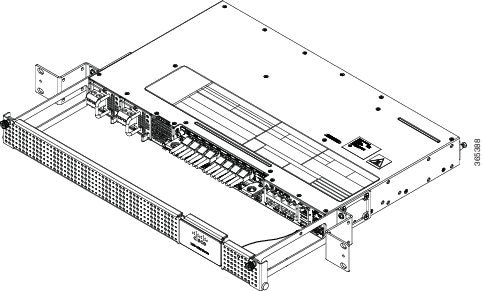
The following figure shows the 3D image of the Cisco NCS 4202:
The following figures show the port numbering for the Cisco NCS 4202:
|
1 |
Power Supply 0 (AC or DC) |
10 |
Alarm port |
|
2 |
Power Supply 1 (AC or DC) |
11 |
Eight Copper port (1G PoE) |
|
3 |
Front Air-Inlet Area |
12 |
ToD port |
|
4 |
GNSS RF IN (SMA threaded connector) |
13 |
Management Port |
|
5 |
SMB Snap-in connector (10MHZ) |
14 |
USB Memory port |
|
6 |
SMB Snap-in connector (1PPS) |
15 |
USB Console port |
|
7 |
Four 1G/10G SFP+ |
16 |
Zero Touch Provisioning button |
|
8 |
Interface Module Slot |
17 |
RS232 Console port |
|
9 |
Four 1G SFP |
18 |
RS232 Aux Console port |
|
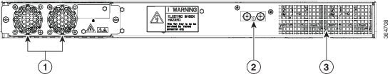
1 |
Fan tray |
3 |
Air vents |
|
2 |
Grounding lug |
— |
Table below describes the other features of Cisco NCS 4202 (AC and DC).
|
Specification |
NCS 4202 |
||
|---|---|---|---|
|
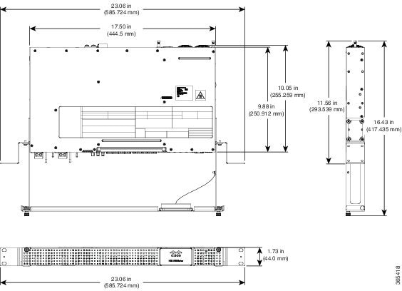
DimensionWidth x Depth x Height |
23.06 x 16.43 x 1.73 inches |
||
|
Weight |
Total weight: 5.63 kg Weight of PSU: 0.59 kg Weight of Fan: 0.33 kg |
||
|
Rack Unit |
EIA one RU |
||
|
Airflow |
Front to back |
||
|
Cable access |
Front cable access |
||
|
System throughput |
60 Gbps, 95 Mpps |
||
|
Power Supply |
|||
|
Redundant |
Yes |
||
|
AC |
Yes |
||
|
Voltage Range |
85V AC to 264V AC, nominal 100/240 VAC |
||
|
Frequency Range |
47 Hz to 63 Hz, nominal 50/60 Hz |
||
|
Maximum Power |
360 W |
||
|
DC |
Yes |
||
|
Voltage Range |
-18 VDC to -32 VDC or -40 VDC to -72 VDC |
||
|
Nominal Voltage Range |
-24 VDC/-48 VDC/-60 VDC |
||
|
Maximum Power |
375 W |
||
|
Heat Dissipation |
— |
||
|
Operating Temperature/Humidity |
–40º C to 70º C |
||
|
Alarms |
|
||
|
Supported Interface Modules |
|
||
|
Mounting option |
Front Z-bracket mount for 23 inches rack |
||
|
Port Configuration |
12x1G and 4x10G/1G ports |
||
|
Port Numbering |
4x10G SFP+ – Port [12:15]
4x1G SFP – Port [8:11] 8x1G PoE RJ45/Cu ports [0:7] |
||
|
Copper/1G/10G Port LEDs |
Link/Activity/Fault |
||
|
Temperature Sensors |
Four temperature sensors |
||
|
1PPS/ToD |
External ports for 1PPS/TOD |
||
|
PoE |
Provides power over Ethernet |
||
|
GNSS |
Connects to the external GPS |
External Interfaces
The external physical interfaces on the front panel of the chassis are given below:
Network Interfaces
The network interfaces are provided through fixed ports.
- GE SFP ports—supports 100/1000 modes
- GE Copper RJ-45 ports—supports 10/100/1000 operation. All eight copper RJ-45 ports support PoE/PoE+/UPoE with overall power budget of 180 W.
Note |
PoE is not supported when the system is powered with 24 V DC. |
- 10GE SFP+—supports 10G/1G mode depending on the SFP+/SFP in the network interface slot.
At 1G mode, it supports only 1000BaseX.
Network Timing Interfaces
- 10MHz input or output—Miniature coaxial connectors for 10MHz timing (input or output). You can use this interfaces with an external GPS device to send or receive clocking from the chassis
- 1PPS input or output and ToD input or output—This interface is used for input or output of time-of-day (ToD) and 1PPS pulses. ToD format includes both NTP and IEEE 1588-2008 time formats.
The same RS422 pins for 1PPS and TOD are shared between input and output directions. The direction for each can be independently configured through software.
- GNSS RF IN—This interface is used to connect the external GPS antenna to the in-built GPS module.
External Alarm Inputs
The chassis supports four dry contact alarm inputs through an RJ-45 jack on the front panel.
Each alarm input can be provisioned as critical, major, minor, or can be configured for normally open or normally closed.
Management Interfaces
The following management interfaces are supported:
Management ENET Port
A single management copper ENET port supporting 100/1000Base-T operation is provided on the front panel. It uses a standard RJ-45 jack.
RS232 Console Port
The RS232 console port provides transmission (Tx), reception (Rx), and ground (Gnd).
Note |
The RS232 console port is enabled only through the Cisco-designed cable adapter USB type A cable to RJ-45 adapter cable. To use this port, disable the flow control on the terminal. |
 Caution |
Do not plug the USB-to-RJ45 adapter cable in the USB Memory port. |
USB Console
A single USB 2.0 Type-A receptacle on the front panel of the chassis provides console access to ROMMON, Cisco IOS-XE and diagnostics. While it uses the Type-A connector, it operates as a USB peripheral only for connection to an external host computer. This interface requires the use of a Type-A to Type-A connector instead of a standard USB cable.
Note |
Use of the USB console is mutually exclusive of the RS232 console port. This interface requires the use of a Type-A to Type-A USB cable. |
USB Mass Storage
A single USB 2.0 Type-A receptacle on the front panel of the chassis allows external USB mass storage devices, such as standard USB flash drives. This interface is used to load images, load or store configurations, write logs, and so on.
Note |
More than 8 GB is not supported in ROMMON mode, |
Zero Touch Provisioning Button
The Zero Touch Provisioning (ZTP) button on the front panel initiates the ZTP process on a short press of less than eight seconds. Pressing the ZTP button for more than eight seconds causes a board reset.
RS232 Auxiliary Console Port
The RS232 Aux console port provides transmission (Tx), reception (Rx), and ground (Gnd).
Note |
The RS232 Aux console port is enabled only through the Cisco-designed cable adapter from USB type A cable to RJ-45 adapter cable. This is a debug-only port. it is recommended that this port be used by field service engineers only. |
Power Supply and Fans
The chassis supports AC, DC, or a combination of both power supplies in a 1+1 redundant configuration.
|
Specification |
AC (A920-PWR400-A) |
DC (A920-PWR400-D) |
|---|---|---|
|
Voltage |
100 V – 240 V |
24 V – 60 V |
|
Current |
5A through a standard C16 type receptacle |
20A through a two-position terminal block |
|
Input Power |
360 W |
375 W |
Note |
This product requires surge protection as part of the building installation. To comply with the Telcordia GR-1089 NEBS standard for electromagnetic compatibility and safety, an external surge protective device (SPD) is required at the AC power service equipment. |
Note |
For DC systems, if a surge of more than 500 V is expected, add an appropriate external surge protective device. |
The chassis has a single fan-tray with four fans. The system is designed to operate at its maximum operating temperature of 70º C, in case of failure of a single fan operating temperature of 65º C. The fan tray is field-replaceable.
LED Indicators
This section describes the different types of LEDs and their behavior.
PWR and STAT LEDs
The PWR LEDs are available on the front panel. These LEDs provide power on the board (PWR) status. During power up state, these LEDs provide booting status and report errors.
Note |
The digital code signing functionality validates the integrity and authenticity of the ROMMON image before booting it. |
|
PWR LED State |
STAT LED state |
Indication |
Comment |
||
|---|---|---|---|---|---|
|
Amber |
Off |
Power in the system is all right and FPGA configuration is taking place. |
Permanent Amber/Off indicates FPGA configuration failure. |
||
|
Amber |
Red |
FPGA Image Validation Error. |
System is in unresponsive state. |
||
|
Flashing Amber and Green alternatively |
Amber |
Upgrade FPGA image error, continuing with Golden FPGA image. |
— |
||
|
Flashing Amber and Green alternatively |
Off |
FPGA configuration successful and Digital code signing successfully validated FPGA image. Digital code signing passed the control to Microloader to boot ROMMON. |
— |
||
|
Flashing Amber and Green alternatively |
Red |
Digital code signing reported failure in ROMMON image validation. |
— |
||
|
Flashing Amber |
Flashing Amber |
ZTP process has begun.
|
Both LEDs turn Green once provisioning is complete. |
||
|
Green |
Off |
IOS-XE image is booting. |
|||
|
Green |
Green |
Successfully booted and system is operating normally. |
— |
||
|
Green |
Amber |
A minor alarm or synchronization is in Holdover or free-running mode |
— |
||
|
Green |
Red |
A major or critical alarm (high temperature reported for any sensor) or multiple fan failure. |
— |
CPU Management Port LEDs
The LED for the 100/1000 Management port is integrated on the connector itself. There are two LEDs in the connector to indicate the Link or Activity status.
|
LED |
LED State |
Indication |
|---|---|---|
|
Left |
Green |
Link up in 1000 Mbps |
|
Blinking Green |
Activity in 1000 Mbps |
|
|
Amber |
Link up in 100 Mbps |
|
|
Blinking Amber |
Activity in 100 Mbps |
|
|
Off |
Link down |
|
|
Right |
Green |
Link up in full duplex with 1000 Mbps speed |
|
Green |
Link up in full duplex with 100 Mbps speed |
|
|
Off |
Link up in half duplex with 100 Mbps speed |
SFP LEDs
Each SFP port has an LED indicator.
|
LED |
LED State |
Indication |
|---|---|---|
|
Labeled same as the SFP port number |
Green |
Link up in 1000Base-X/100Base-FX |
|
Blinking Green |
Activity in 1000 Base-X/100Base-FX |
|
|
Amber |
Fault/Error/Link down |
|
|
Off |
Administratively down |
SFP+ LEDs
Each SFP+ port has an LED indicator.
|
LED |
LED State |
Indication |
|---|---|---|
|
Labeled same as the SFP port number |
Green |
Link up in 10G/1G |
|
Blinking Green |
Activity in 10G/1G |
|
|
Amber |
Fault/Error/Link down |
|
|
Off |
Administratively down |
RJ-45 LEDs
There is only one LED on each RJ45 port on the fixed slot (slot 0/0) and this indicates only the link or speed status. There is no LED to show the Duplex state. However, there are two LEDs for IM RJ45 ports and they indicate the Link and Duplex state.
|
LED State |
Indication |
|---|---|
|
Green |
Link up in 10/100/1000Base-T |
|
Blinking Green |
Activity in 10/100/1000Base-T |
|
Amber |
Fault/Error/Link down |
|
Off |
Administratively down |
Power Supply Unit LEDs
Each power supply unit has a corresponding LED on the front panel.
|
Power LED |
FAIL LED |
Power Supply Condition |
|---|---|---|
|
Green |
Off |
Power Supply ON; valid input/output |
|
Yellow 1Hz blinking |
Red 1Hz blinking |
PSU Warning due to OCP, OTP, UV, OV, OP, abnormal fan operation PSU continues to operate |
|
Off |
On |
PSU failure due to OCP, OTP, UV, OV, OP, abnormal fan operation. No valid output. |
|
Green 1Hz blinking |
Off |
Valid power present, shutdown by system. |
|
Yellow |
Off |
Input voltage low |
|
Off |
Off |
No valid power input. |
System–Interface LED Behavior
|
Event |
1G Copper Port LEDs (Link) |
1G SFP Port LEDs |
|---|---|---|
|
ROMMON |
Off |
Off |
|
IOS Shut |
Off |
Off |
|
IOS No shut (cable disconnect) |
Amber |
Amber |
|
IOS No shut (Link Up) |
Green |
Green |
|
Event |
Dual Rate (1G/10G) Port LEDs |
|---|---|
|
ROMMON |
Off |
|
IOS Shut |
Off |
|
IOS No shut (cable disconnect) |
Amber |
|
IOS No shut (Link Up) |
Green |
|
Event |
Management Port LEDs (Link/Duplex) |
|---|---|
|
ROMMON |
Green/Off |
|
IOS Shut |
Off/Off |
|
IOS No shut (cable disconnect) |
Amber/Off |
|
IOS No shut (cable connect) |
Green/Green in 1G mode Amber/Green in 100M mode |
Online Insertion and Removal
This chassis supports the following OIR operations:
- When an SFP is removed, there is no effect on traffic flowing on other ports.
- When an SFP is installed, the system initializes that port for operation based upon the current configuration. If the inserted SFP is incompatible with the current configuration for that port, the port does not become operational until the configuration is updated.
- Both power supplies are installed and active and the load may be shared between them or a single PSU could support the whole load. When a power supply is not working or the input cable is removed, the remaining power supply takes the entire load without disruption.
Caution |
Do not remove or replace the fan tray with the chassis powered on. |
 Feedback