Line Card LEDs
The Cisco NCS 1014 line cards use LEDs to indicate the overall state of the cards and help you verify the status of specific connections, ports, and system components. The following topics identify these LEDs and explain what they mean.
 Note |
|
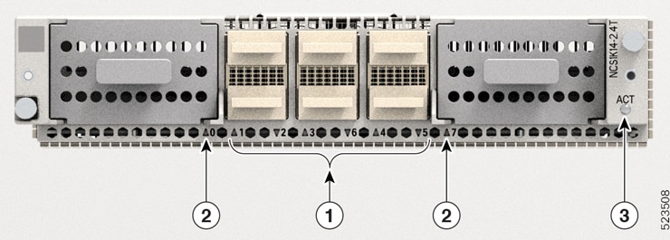
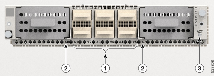
2.4T and 2.4TX Line Cards LED
The 2.4T and 2.4TX line cards have nine LEDs to indicate the line port alarm status.
|
Callout |
LED |
|---|---|
|
1 |
QSFP port (1–6) LEDs The card cage embeds the QSFP LEDs. The triangles appearing upwards and downwards indicate the status and position of the corresponding QSFP. |
|
2 |
Trunk port (0 and 7) LEDs |
|
3 |
ACT LED |
Note |
The LED status applies to both 2.4T and 2.4TX line cards. |
|
LED |
Color |
Status |
|---|---|---|
|
ACT LED1 |
Amber (solid) |
The line card is booting. This color appears as soon as the line card is inserted into the chassis. |
|
Flashing Red |
The line card is in the booting phase. |
|
|
Green |
The line card is up and operational (not associated to the traffic status). |
|
| QSFP and Trunk port LEDs (0…7) |
Off |
The port remains not provisioned or switched off. |
|
Green |
The module is operational and has no alarm. |
|
|
Amber (solid) |
Minor alarm (such as low Rx or Tx power) that could lead to a traffic-impacting situation. |
|
|
Amber (flashing) |
Used for troubleshooting. Identifies the faulty port of an LC. Use the controller optics command in the configuration mode to point to a faulty port in the line card. The port is configured in maintenance mode or the attention LED is enabled for this port. Use hw-module location to enable the attention LED for the port. |
|
|
Red |
Major alarm that could lead to a traffic-impacting situation. |
From R24.4.1, status of the trunk LEDs (0 and 7) are enhanced to reflect the conditions of the CIM8 pluggable.
|
LED |
Condition of the CIM8 pluggable |
Color reported on CLI |
Color on the port LED (physically) |
Note |
|---|---|---|---|---|
|
Trunk port LEDs (0 and 7) |
Pluggable is inserted. Both captive screws in the pluggable are tightened. Datapath controllers for the pluggable are configured. |
red/green |
red/green |
Based on the alarms that are raised, the LED reports red or green. |
|
Pluggable is inserted. Datapath controllers for the pluggable are configured. But, either one or both captive screws in the pluggable remain open. |
red |
red (flashing) |
Raises Improper removal alarm. |
|
|
Datapath controllers for the pluggable are configured. But, the pluggable is removed. |
red |
red |
Raises Improper removal alarm. |
|
|
Pluggable is inserted. Both captive screws in the pluggable are tightened. But, the datapath controllers for the pluggable are not configured. |
red (flashing) to off |
off |
Raises no alarm. |
|
|
Pluggable is inserted. But, either one or both captive screws in the pluggable remain open. Datapath controllers for the pluggable are not configured. |
off |
red (flashing) |
Raises no alarm. |
|
|
Pluggable is removed. Datapath controllers for the pluggable are not configured. |
off |
off |
Raises no alarm. |
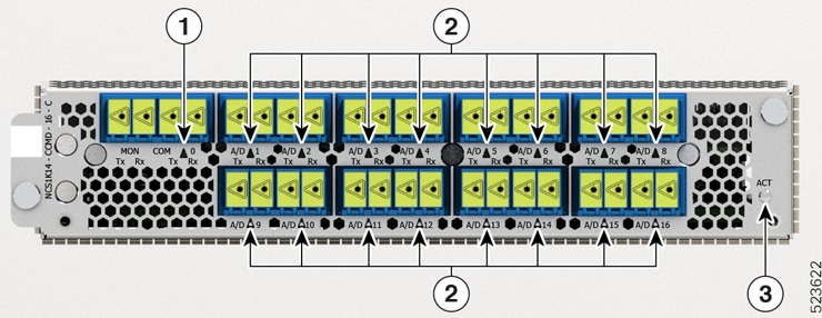
CCMD-16-C and CCMD-16-L Line Card LED
The CCMD-16-C and CCMD-16-L optical line cards have 18 LEDs each to indicate the system status and the status of the optical ports.
The following information applies to both CCMD-16-C and CCMD-16-L cards.
|
Callout |
LED |
|---|---|
|
1 |
COM |
|
2 |
A/D-1…A/D-16 |
|
3 |
ACT |
|
LED |
Color |
Status |
|
|---|---|---|---|
|
ACT |
Amber (solid) |
The line card is booting. This color appears when you insert the line card into the chassis. |
|
|
Flashing Red |
The line card is faulty. |
||
|
Green |
The line card is up and operational—not associated to the traffic status. |
||
|
COM, A/D-1…A/D-16 |
Off |
The port is not provisioned. |
|
|
Red |
Major alarm that could lead to a traffic impacting situation. |
||
|
Green |
The module is operational and has no alarm. |
||
|
Amber (solid) |
Minor alarm (such as low Rx or Tx power) that could lead to a traffic impacting situation. |
||
|
Amber (flashing) |
This is used for troubleshooting, to identify the faulty port of an LC. Use the controller optics command in the configuration mode to point to a faulty port in the LC. The port is configured in maintenance mode or the attention LED is enabled for this port.
|
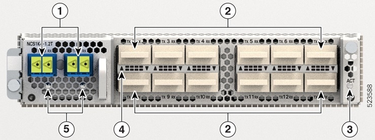
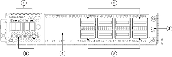
1.2T and 1.2T Licensed Line Cards LEDs1.2T, 1.2TL, and 2-QDD-C Line Cards LEDs
The 1.2T and 1.2T licensed line cards have 14 LEDs and 2-QDD-C line cards have 12 LEDs to indicate the line port alarm status.
The LEDs information applies to 2-QDD-C, 1.2T, and 1.2T licensed cards.
|
1 |
Trunk ports (0 and 1) |
|
2 |
|
|
3 |
ACT LED |
|
4 |
QSFP port LEDs The LEDs for the QSFPs are embedded in the card cage. The triangles shown upwards or downwards (in 2-QDD-C, 1.2T and 1.2TL line cards) indicate the status of the corresponding QSFP. |
|
5 |
Trunk port LEDs |
|
LED |
Color |
Status |
|
|---|---|---|---|
|
Attention LED |
Yellow Flashing |
Used by the field engineers to identify a specific port in the line card. This is used for troubleshooting purposes.
|
|
|
ACT LED |
Amber (solid) |
The line card is booting. This colour appears as soon as the line card is inserted in to the chassis. |
|
|
Flashing Red |
The line card is in the booting phase. |
||
|
Green |
The line card is up and operational (not associated to the traffic status). |
||
|
QSFP and Trunk port LEDs |
Off |
The port has not been provisioned. |
|
|
Red |
Major alarm that could lead to a traffic-impacting situation. |
||
|
Green |
Indicates that the module is operational and has no alarm. |
||
|
Amber (solid) |
Indicates a minor alarm (such as low Rx or Tx power), which could lead to a traffic impacting situation. |
||
|
Amber (flashing) |
This is used for troubleshooting, to identify the faulty port of a line card. Use the controller optics command in the configuration mode to point to a faulty port in the line card. The port is configured in maintenance mode or the attention LED is enabled for this port.
|
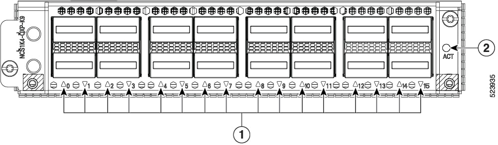
QXP Line Card LED
The front view of the QXP-K9 line card is as below.
|
1 |
16 QSFP-DD ports (0 to 15) |
|
2 |
ACT LED |
|
LED |
Color |
Status |
|---|---|---|
|
ACT LED |
Flashing Red |
The line card is booting. This color appears as soon as the line card is inserted in to the chassis. |
|
Amber (solid) |
Indicates that the line card is in the booting phase. |
|
|
Green |
Indicates that the line card is up and operational (not associated to the traffic status). |
|
|
QSFP-DD port LEDs |
Off |
This indicates that the port has not been provisioned. |
|
Red |
Indicates a major alarm, which could be a traffic impacting situation. |
|
|
Green |
Indicates that the module is operational and has no alarm. |
|
|
Amber (solid) |
Indicates a minor alarm (such as low Rx or Tx power), which could lead to a traffic impacting situation. |
|
|
Amber (flashing) |
This is used for troubleshooting, to identify the faulty port of a line card. Use the controller optics command in the configuration mode to point to a faulty port in the line card. |
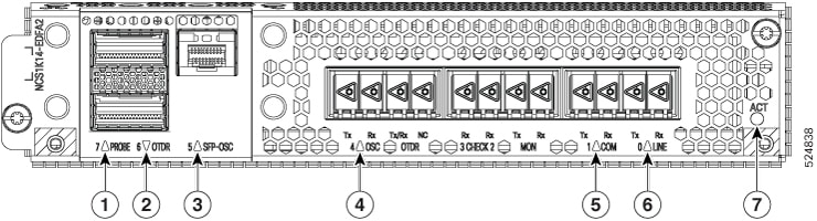
EDFA2 Line Card LED
The EDFA2 line card has seven LEDs to indicate the QSFP-DD and LC port alarm status.
|
Callout |
LED |
|---|---|
|
1 |
PROBE 7 |
|
2 |
OTDR 6 |
|
3 |
SFPP-OSC 5 |
|
4 |
OSC 4 |
|
5 |
COM 1 |
|
6 |
LINE 0 |
|
7 |
ACT |
|
LED |
Color |
Status |
|---|---|---|
|
ACT LED2 |
Amber (solid) |
The line card is booting. This color appears as soon as the line card is inserted into the chassis. |
|
Flashing Red |
The line card is in the booting phase. |
|
|
Green |
The line card is up and operational (not associated to the traffic status). |
|
|
PROBE 7 SFP-OSC 5 OSC 4 COM 1 LINE 0 |
Off |
The port remains not provisioned or switched off. |
|
Green |
The module is operational and has no alarm. |
|
|
Amber (solid) |
Minor alarm (such as low Rx or Tx power) that could lead to a traffic-impacting situation. |
|
|
Amber (flashing) |
Used for troubleshooting. Identifies the faulty port of an LC. Use the controller optics command in the configuration mode to point to a faulty port in the line card. The port is configured in maintenance mode or the attention LED is enabled for this port. Use hw-module location to enable the attention LED for the port. |
|
|
Red |
Major alarm that could lead to a traffic-impacting situation. |
|
|
OTDR 6 port |
Red |
The module is not present. |
|
Yellow |
OTDR scan is in progress. |
|
|
Green |
The module is present. |

 Feedback