ILA controller models in NCS 1010
This reference lists all the ILA controller models available for the Cisco NCS 1010 platform and details the mapping between their physical ports and controllers. Use this information to identify controller-port assignments for supported in-line amplifier (ILA) line cards, including release-specific models and supported features.
ILA controller models
The ILA controller model is available for the NCS 1010 ILA line cards:
-
NCS1K-ILA-C: C-band In-Line Amplifier without Raman
-
NCS1K-ILA-R-C: C-band In-Line Amplifier with one side Raman
-
NCS1K-ILA-2R-C: C-band In-Line Amplifier with both sides Raman
-
NCS1K-ILA-L: L-band In-Line Amplifier without Raman
-
NCS1K-E-ILA-R-C: C-band In-Line Amplifier with East-facing Raman, Enhanced
-
NCS1K-E-ILA-2R-C: C-band In-Line Amplifier with both sides Raman, Enhanced
-
NCS1K-E-ILA-R-C-2: C-band In Line Amplifier with West-facing Raman, Enhanced
 Note |
For release information of the ILA line cards, refer to Hardware Installation Guide for Cisco NCS 1010 and Cisco NCS 1000 Passive Modules. |
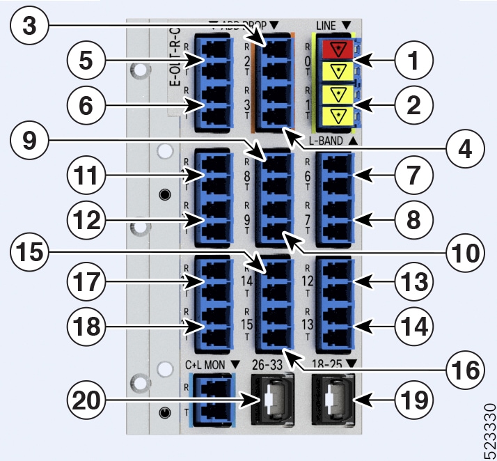
Port and controller mapping for each ILA line card
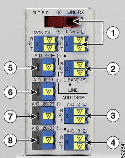
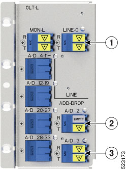
The figures and tables show the three ILA variants and the mapping between physical ports and controllers:
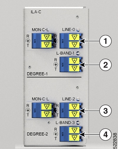
|
Callout |
Port labl |
Controller types |
|---|---|---|
|
1 |
LINE-0 |
Parent Controller: OTS0/0/0/0 Child Controller: OSC0/0/0/0, Line OTS-OCH 0/0/0/0/x |
|
2 |
L-BAND-1 |
Parent Controller: OTS0/0/0/1 |
|
3 |
LINE-2 |
Parent Controller: OTS0/0/0/2 Child Controller: OSC0/0/0/2, Line OTS-OCH 0/0/0/2/x |
|
4 |
L-BAND-3 |
Parent Controller: OTS0/0/0/3 |
|
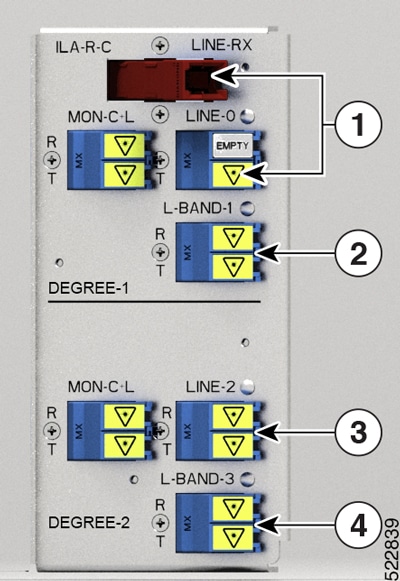
Callout |
Port labl |
Controller types |
|---|---|---|
|
1 |
RAMAN pump and LINE-0 |
Parent Controller: OTS0/0/0/0 Child Controller: OSC0/0/0/0, DFB0/0/0/0, Line OTS-OCH 0/0/0/0/x |
|
2 |
L-BAND-1 |
Parent Controller: OTS0/0/0/1 |
|
3 |
LINE-2 |
Parent Controller: OTS0/0/0/2 Child Controller: OSC0/0/0/2, Line OTS-OCH 0/0/0/2/x |
|
4 |
L-BAND-3 |
Parent Controller: OTS0/0/0/3 |
|
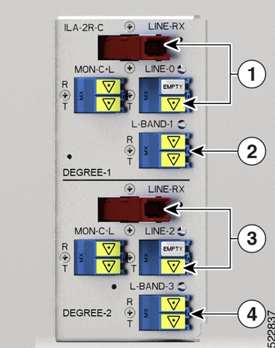
Callout |
Port labl |
Controller types |
|---|---|---|
|
1 |
RAMAN pump and LINE-0 |
Parent Controller: OTS0/0/0/0 Child Controller: OSC0/0/0/0, DFB0/0/0/0, Line OTS-OCH 0/0/0/0/x |
|
2 |
L-BAND-1 |
Parent Controller: OTS0/0/0/1 |
|
3 |
RAMAN pump and LINE-2 |
Parent Controller: OTS0/0/0/2 Child Controller: OSC0/0/0/2, DFB0/0/0/2, Line OTS-OCH 0/0/0/2/x |
|
4 |
L-BAND-3 |
Parent Controller: OTS0/0/0/3 |
|
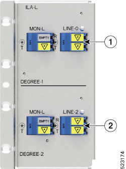
Callout |
Port labl |
Controller types |
|---|---|---|
|
1 |
LINE-0 |
Parent Controller: OTS0/0/0/0 Child Controller: OSC0/0/0/0, Line OTS-OCH 0/0/0/0/x |
|
2 |
LINE-2 |
Parent Controller: OTS0/0/0/2 Child Controller: OSC0/0/0/2, Line OTS-OCH 0/0/0/2/x |
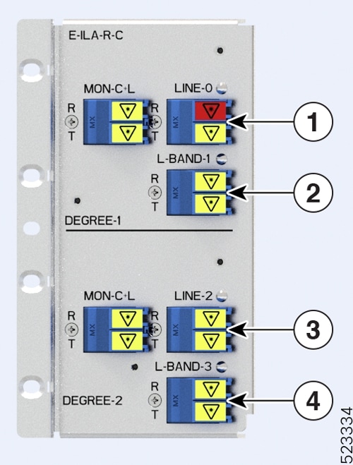
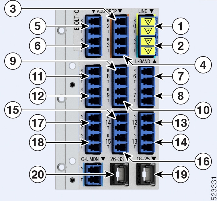
The figures and tables show the three ILA variants that are introduced in Release 7.10.1 and the mapping between their physical ports and controllers:
Note |
The new ILA variants have ports that are highlighted in red to indicate the Raman ports. |
|
Callout |
Port labl |
Controller types |
|---|---|---|
|
1 |
RAMAN port and LINE-0 |
Parent Controller: OTS0/0/0/0 Child Controller: OSC0/0/0/0, DFB0/0/0/0, Line OTS-OCH 0/0/0/0/x |
|
2 |
L-BAND-1 |
Parent Controller: OTS0/0/0/1 |
|
3 |
LINE-2 |
Parent Controller: OTS0/0/0/2 Child Controller: OSC0/0/0/2, Line OTS-OCH 0/0/0/2/x |
|
4 |
L-BAND-3 |
Parent Controller: OTS0/0/0/3 |
|
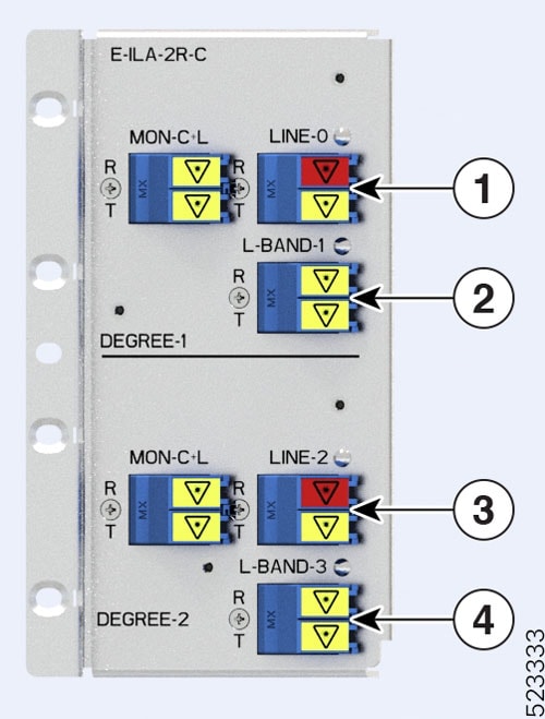
Callout |
Port labl |
Controller types |
|---|---|---|
|
1 |
RAMAN port and LINE-0 |
Parent Controller: OTS0/0/0/0 Child Controller: OSC0/0/0/0, DFB0/0/0/0, Line OTS-OCH 0/0/0/0/x |
|
2 |
L-BAND-1 |
Parent Controller: OTS0/0/0/1 |
|
3 |
RAMAN port and LINE-2 |
Parent Controller: OTS0/0/0/2 Child Controller: OSC0/0/0/2, DFB0/0/0/2, Line OTS-OCH 0/0/0/2/x |
|
4 |
L-BAND-3 |
Parent Controller: OTS0/0/0/3 |
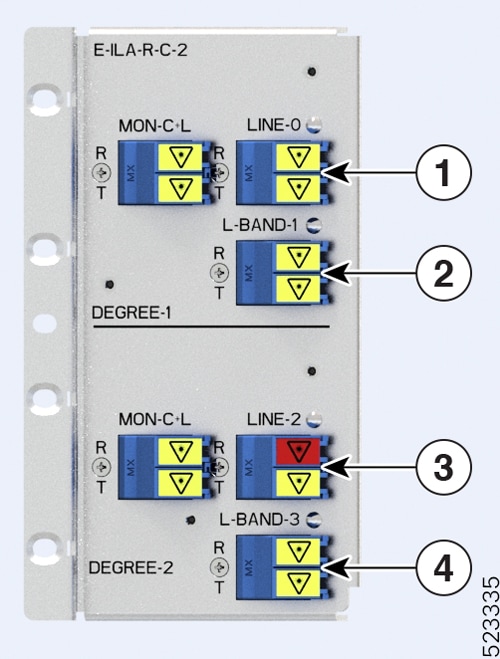
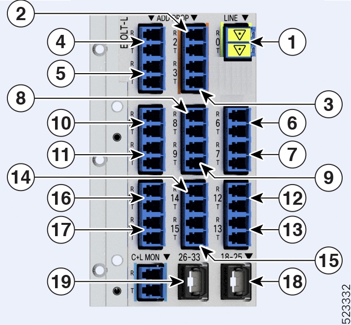
The figure and table show the new ILA variant that is introduced in Release 7.11.1 and the mapping between its physical ports and controllers:
|
Callout |
Port labl |
Controller types |
|---|---|---|
|
1 |
LINE-0 |
Parent Controller: OTS0/0/0/0 Child Controller: OSC0/0/0/0, Line OTS-OCH 0/0/0/0/x |
|
2 |
L-BAND-1 |
Parent Controller: OTS0/0/0/1 |
|
3 |
RAMAN port and LINE-2 |
Parent Controller: OTS0/0/0/2 Child Controller: OSC0/0/0/2, DFB0/0/0/2, Line OTS-OCH 0/0/0/2/x |
|
4 |
L-BAND-3 |
Parent Controller: OTS0/0/0/3 |
 Feedback