Cisco NCS 1010 Topologies

This appendix describes multidegree support on NCS 1010 and has examples of a few NCS 1010 topologies.

Multidegree ROADM networks with NCS1010 OLT devices

A multidegree ROADM network is a network capability that enables a single ROADM node to establish more than two degrees of connection.

A degree is a bidirectional physical fiber connection between two nodes in a network.

NCS 1010 multidegree ROADM express

ROADM express refers to the pass-through wavelengths that travel directly from one fiber degree to another inside a ROADM node, bypassing local add/drop without optical-electrical-optical (OEO) conversion.

NCS1010 OLT devices support up to eight degrees of ROADM express through NCS1K-BRK-8 (BRK-8) modules. The BRK-8 modules help in MPO breakout for express interconnect. For a multidegree network, use as many BRK-8 modules and OLT devices as there are degrees. The BRK-8 modules help NCS 1010 nodes to achieve multidegree capability.

BRK-8 modules are essential for scaling network degrees and supporting express interconnects in advanced optical networking scenarios.

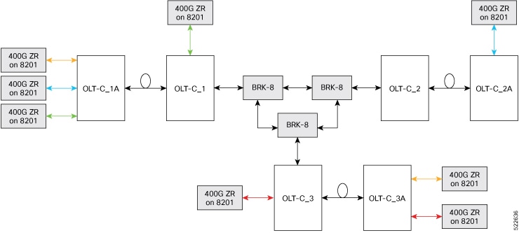
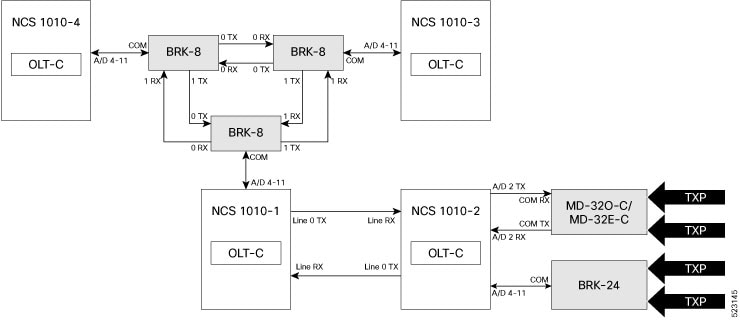
Three-degree ROADM network using NCS 1010 devices

In this example, a three-degree ROADM network established an express interconnection among three different point-to-point multispan optical networks. The three point-to-point topologies are:

  • OLT-C_1A to OLT-C_1

  • OLT-C_2A to OLT-C_2

  • OLT-C_3A to OLT-C_3

The three OLT nodes (OLT-C_1, OLT-C_2, OLT-C_3) are each connected using three BRK-8 modules. Each module must link to the other two, providing the necessary express interconnect. ptical cross-connects in each OLT ensure signals can traverse to any of the three endpoints, even across multiple spans including intermediate ILA nodes.

The three-degree ROAMD network with NCS 1010 devices contains

  1. OLT-C_1, OLT-C_2, and OLT-C_3 nodes connected to each other using three BRK-8 modules.

  2. Each BRK-8 module is connected to each of the other BRK-8 modules for express interconnect that enables multidegree support.

  3. Each OLT device has optical cross-connection to each other to enable the signal to reach the target OLT.

Figure 1. Typical 3-Degree Topology
Figure representing typical 3-degree topology

Types of NCS 1010 sample topologies

This section describes three sample topologies of specific hardware deployments.

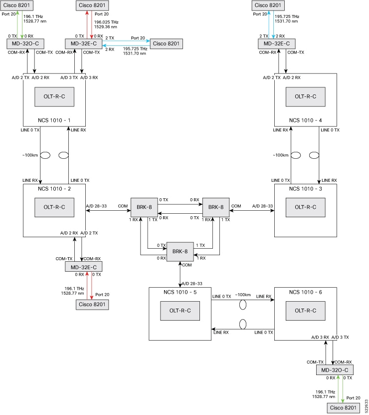
Colored multidegree topologies

A colored multidegree topology is a network design pattern that

  • interconnects sites using multiple optical degrees,

  • supports optical channels from transponders with low transmit (TX) power such as ZR or ZR+ pluggable modules, and

  • operates with channel TX power spectral density between -21 dBm/12.5 GHz and -14 dBm/12.5 GHz.

Topology components

This topology typically requires:

  • Cisco NCS 1010 devices

  • NCS1K-MD32E-C modules

  • NCS1K-MD32O-C modules

  • NCS1K-BRK-8 modules

  • Cisco 8201 routers

  • QDD-400G-ZR-S transceivers

  • LC/LC cables

  • MPO cables

Figure 2. Colored solution
A diagram representing the colored multidegree topology with devices and port connections

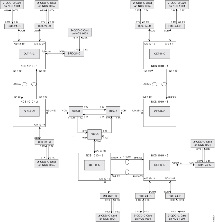
Colorless multidegree topologies

A colorless multidegree topology is a network design pattern that

  • uses multi-degree site interconnections with flexible wavelength assignment,

  • supports optical channels from high TX power transponders like 1.2T line cards or CFP2-400G-DCO trunk interfaces, and

  • requires channel TX power spectral density not lower than -7 dBm/12.5 GHz.

Components required

Deployment typically includes:

  • Cisco NCS 1010 devices

  • NCS1K-BRK-8 modules

  • NCS1K-BRK-24 modules

  • CFP2-400G-DCO transceivers

  • Cisco NCS 1004 devices

  • NCS1K4-2-QDD-C-K9 line card

  • LC/LC cables

  • MPO cables

Figure 3. Colorless solution
A diagram representing the colorless multidegree topology with devices and port connections

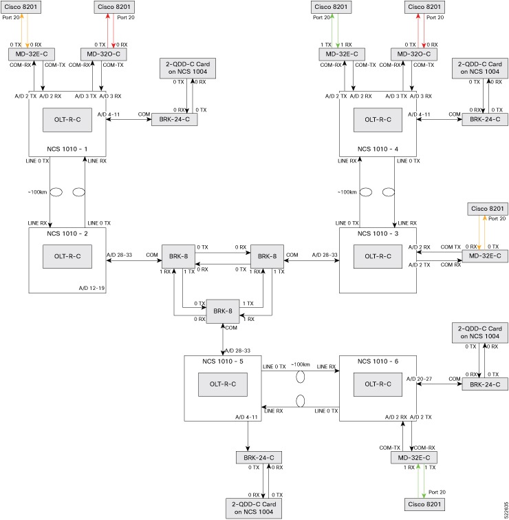
Hybrid multidegree topologies

A hybrid multidegree topology is a network design pattern that

  • interconnects sites using both colored and colorless optical channels,

  • accommodates a mix of high- and low-TX power transponders within the same deployment, and

  • leverages the channel TX power spectral density ranges required for both colored and colorless topologies.

Components required

Supported hardware includes:

  • Cisco NCS 1010 devices

  • NCS1K-MD32E-C modules

  • NCS1K-MD32O-C modules

  • NCS1K-BRK-8 modules

  • NCS1K-BRK-24 modules

  • Cisco 8201 routers

  • QDD-400G-ZR-S transceivers

  • CFP2-400G-DCO transceivers

  • Cisco NCS 1004 devices

  • NCS1K4-2-QDD-C-K9 line card

  • LC/LC cables

  • MPO cable

Figure 4. Colorless solution
A diagram representing the hybrid multidegree topology with devices and port connections

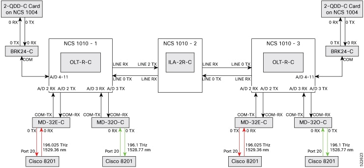
Point-to-point topologies

A point-to-point topology is a network design pattern that

  • connects two network sites directly using optical links,

  • limits the number of degrees per site to two or fewer, and

  • enables simple deployment with minimal hardware requirements.

Components for point-to-point topology

To build this topology, you need these hardware components.

  • Cisco NCS 1010 devices: OLT-R-C for and ILA-2R-C for inline amplication

  • NCS1K-MD32E-C modules: Multiplex and demultiplex C-band signals in even channels.

  • NCS1K-MD32O-C modules: Multiplex and demultiplex C-band signals in odd channels.

  • NCS1K-BRK-24 modules: 24-degree MPO breakout modules for express interconnection.

  • QDD-400G-ZR-S transceiver: QSFP-DD transceiver module, coherent DCO, 400G-ZR for transmiting 400G payload at 16QAM modulation

  • MPO/MPO cables: Used for fiber-optic connectivity between NCS 1010 devices and BRK-24 modules.

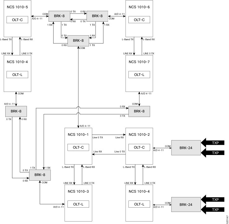
  • LC/LC cables: Used for fiber-optic connectivity between BRK-24 and mux/demux modules.

This image shows the point-to-point topology.

Figure 5. Point-to-point topology
A diagram representing the point-to-point topology with the devices and port connections

Omnidirectional topologies

An omnidirectional topology is a network architecture that

  • enables each optical channel to be dynamically routed through any available degree of a multidegree node,

  • allows channel rerouting after fiber cuts without requiring physical fiber reconnections, and

  • supports flexible and scalable add/drop configurations for redundancy or increased capacity.

Omnidirectional topologies are often implemented in optical networks using open-line terminal (OLT) hardware and compatible passive modules. They are supported over C+L bands and can scale beyond four network degrees. Dual omnidirectional add/drop configurations provide increased reliability and add/drop bandwidth.

NCS2K-MF-4x4-COFS based colorless omnidirectional topologies

A colorless omnidirectional topology is an optical network configuration that

  • uses colorless modules to add or drop channels without wavelength constraints,

  • aggregates and routes channels from multiple degrees using compatible passive hardware assemblies, and

  • enables retuning of channel frequencies or wavelengths from connected transponders or muxponders without physical cabling changes.

Topology Components

To build this topology, you need the following hardware:

  • NCS 1010 OLT devices

  • NCS2K-MF-4x4-COFS modules

  • NCS2K-MF-MPO-8LC modules

  • NCS1K-BRK-8 modules

Specific cable configurations for interconnecting the modules:

  • The MF-4x4-COFS modules are interconnected using standard MPO 8 or 12 fibers (15454-MPO-MPO-x or ONS-12MPO-MPO-x )

  • The MF-4x4-COFS modules and NCS1K-BRK-8 module are interconnected using standard LC-LC fibers.

This image shows the COFS-based colorless omnidirectional topology

Figure 6. MF-4x4-COFS based colorless omnidirectional topology

Limitations

  • This configuration is supported only for C-band ROADM.

  • This configuration is scalable only up to a maximum of 4 degrees. More OSNR penalty is induced by the MF-4x4-COFS as you add more degrees.

  • One MF-4x4-COFS module can support up to only four channels. To scale up to 32 channels, you would require 8 MF-4x4-COFS modules.

  • The terminal node in this configuration can be connected only to NCS 1004 line cards, line cards with CFP2-400G-DCO as a trunk interface, and DP04QSDD pluggable.

OLT-based omnidirectional add/drop topologies

OLT-based omnidirectional add/drop topologies are optical network designs that

  • implement omnidirectional routing by interconnecting OLT devices such as OLT-C and OLT-L back-to-back,

  • enable multiple add/drop stages within a single ROADM site, improving flexibility and scalability, and

  • support integration with a variety of transponders and trunk interfaces without major restrictions.

Topology components

To build this topology, you need the following hardware:

  • NCS 1010 OLT-C devices

  • NCS 1010 OLT-L devices

  • NCS1K-BRK-24 modules

  • NCS1K-BRK-8 modules

  • NCS1K-MD32-C modules

Specific configurations and applications that are required for this configuration:

  • The interconnection between the terminal OLT-C, where the traffic is terminated and the omnidirectional degree is managed as a 0dB span.

  • OSC-C and OSC-L controllers can be used with unnumbered IP on OSC interfaces of the omni span.

  • Link tuner and Gain estimator must be disabled on the Omni span.

  • APC must be enabled on Omni span.

  • ASE loading is enabled (both static and dynamic).

  • Specific configuration for optical applications such as span length and fiber type are not required.

  • To have the Preamplifier of OLT-C working in proper condition (minimum gain 12dB), the Line-Tx PSD must be set to –12.9 dBm/12.5 GHz (considering 80% CH_SD).

Figure 7. Omnidirectional configuration with OLTs
Figure 8. Dual omnidirectional configuration
Figure 9. C+L omnidirectional configuration

Limitations

  • Link tuner and gain estimator features must be disabled on Omni spans.

  • Proper functioning of terminal OLT-C preamplifiers requires precise power spectral density (PSD) settings.

  • Optical supervisory channel controllers (OSC-C and OSC-L) can be used with unnumbered IP addressing.