DWDM Node Configurations
The ONS 15454 supports the following DWDM node configurations: hub, terminal, optical add/drop multiplexing (OADM), reconfigurable OADM (ROADM), anti-amplified spontaneous emission (anti-ASE), line amplifier, optical service channel (OSC) regeneration line, multishelf nodes, and node configurations for mesh networks. All node configurations can be provisioned with C-band or L-band cards except the OADM and anti-ASE nodes. These nodes require AD-xB-xx.x or AD-xC-xx.x cards, which are C-band only. All node configurations can be single-shelf or multishelf.
 Note |
The Cisco Transport Planner tool creates a plan for amplifier placement and proper node equipment. |
Note |
To support multiple optical sides in mesh DWDM networks, east and west are no longer used to reference the left and right sides of the ONS 15454 shelf. If a network running a previous software release is upgraded to this release, west will be mapped to A and east to B. In two-sided nodes, such as a hub or ROADM node, Side A refers to Slots 1 through 6 and Side B refers to Slots 12 through 17. Terminal nodes have one side labeled “A,” regardless of which slots have cards installed. For more information about configuring the ONS 15454 in mesh DWDM networks, see the Configuring Mesh DWDM Networks |
Terminal Node
A terminal node is a single node equipped with two control cards and one of the following combinations:
-
One 32MUX-O card and one 32DMX-O card
-
One 32WSS card and either a 32DMX or a 32DMX-O card
-
One 40-WSS-C or 40-WSS-CE card and one 40-DMX-C or 40-DMX-CE card
-
One 40-MUX-C and one 40-DMX-C or 40-DMX-CE card
-
One 80-WXC-C card, one 15216-MD-40-ODD, 15216-EF-40-ODD, or 15216-MD-48-ODD patch panel, and one 15216-MD-40-EVEN, 15216-EF-40-EVEN, or 15216-MD-48-EVEN (15216 40 or 48-channel mux/demux patch panel), and 15216-MD-ID-50 or 15216-MD-48-CM
-
16-WXC-FS, MF-MPO-8LC, MF-4x4-COFS, MF-16AD-CFS, MF-DEG-5, MF-UPG-4, OPT-EDFA-xx, RAMAN-CTP (optional), RAMAN-COP, EDRA2-yy
-
One 40-SMR1-C and one 15216-MD-40-ODD, 15216-EF-40-ODD, or 15216-MD-48-ODD patch panel
-
One 40-SMR2-C and one 15216-MD-40-ODD, 15216-EF-40-ODD, or 15216-MD-48-ODD patch panel
Note
Although it is recommended that you use the 15216-MD-40-ODD, 15216-EF-40-ODD, or 15216-MD-48-ODD patch panel along with the 40-SMR1-C and 40-SMR2-C cards, you can alternatively use the 40-MUX-C and 40-DMX-C cards instead of the 15216-EF-40-ODD, or 15216-MD-48-ODD patch panel.
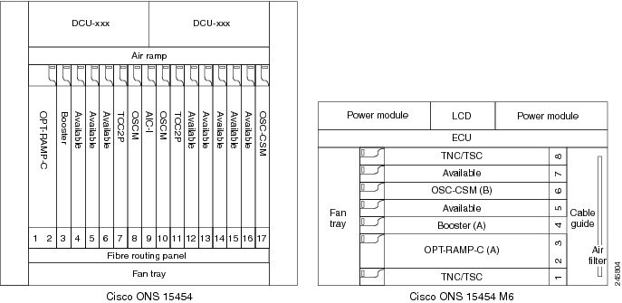
Cards in the terminal nodes can be installed in Slots 1 through 6 or Slots 12 through 17. The side where cards are installed is always assigned as Side A.
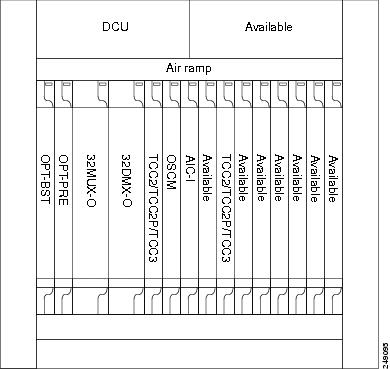
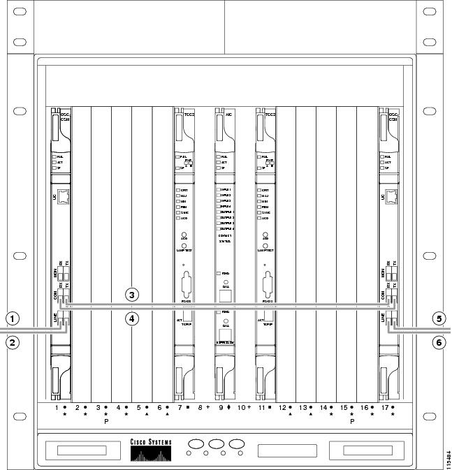
The following figure shows an example of a terminal configuration with a 32MUX-O card installed. The channel flow for a terminal node is the same as the hub node.
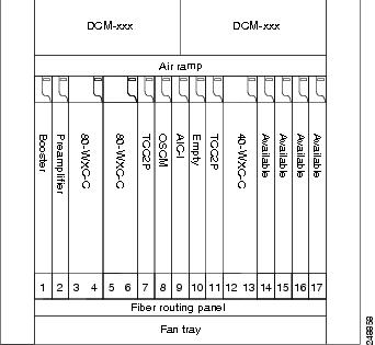
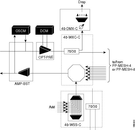
The following figure shows an example of a terminal configuration with a 40-WSS-C card installed.
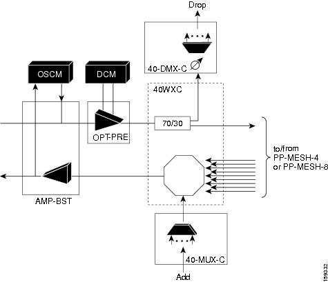
The following figure shows an example of a terminal configuration with a 40-MUX-C card installed.
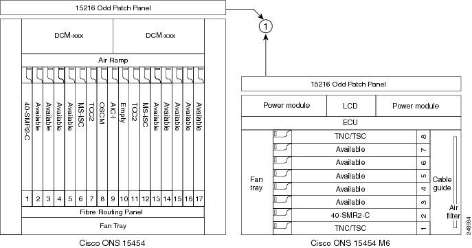
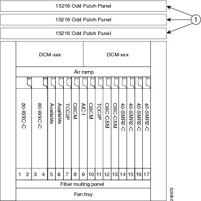
The following figure shows an example of a terminal configuration with a 40-SMR1-C card installed.

|
1 |
15216-MD-40-ODD, 15216-EF-40-ODD, or 15216-MD-48-ODD patch panel |
The following figure shows an example of a terminal configuration with 40-SMR1-C and booster amplifier cards installed.
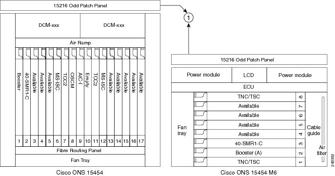
|
1 |
15216-MD-40-ODD, 15216-EF-40-ODD, or 15216-MD-48-ODD patch panel |
Note |
When you use the 40-SMR1-C card along with a booster amplifier, the OSCM card must be connected to the booster amplifier. |
The following figure shows an example of a terminal configuration with a 40-SMR2-C card installed.
|
1 |
15216-MD-40-ODD, 15216-EF-40-ODD, or 15216-MD-48-ODD patch panel |
The following figure shows an example of a 80-channel terminal configuration with RAMAN-CTP and RAMAN-COP cards installed.
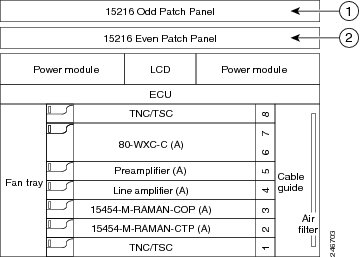
|
1 |
15216-MD-40-ODD, 15216-EF-40-ODD, or 15216-MD-48-ODD patch panel |
|
2 |
15216-MD-40-EVEN, 15216-EF-40-EVEN, or 15216-MD-48-EVEN patch panel |
The following figure shows an example of a 16-channel terminal configuration with16-WXC-FS, amplifiers, MPO connector, and TXP cards.
- Terminal Node with 16-WXC-FS Up to 16 Channels -Cisco ONS 15454 M6
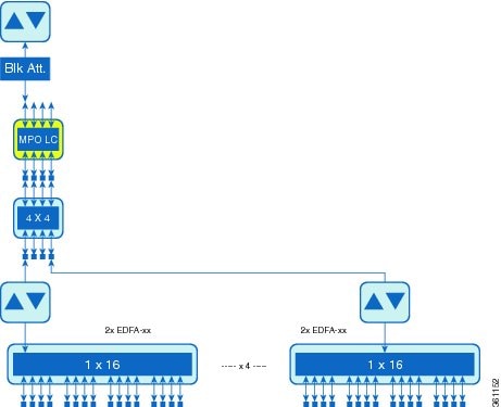
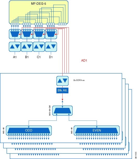
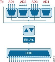
The following figure shows an example of a 64-channel colorless terminal configuration with16-WXC-FS, amplifiers, MPO connector, 4x4-COFS, and 16AD-CFS. In the absence of power regulation in the ADD path, bulk attenuators are needed to fit with EDFA input power dynamic.
The following figure shows an example of a 96-channel colorless omni-directional terminal configuration with16-WXC-FS, amplifiers, MPO connector, and 16AD-CFS.
- Terminal Node with 16-WXC-FS Up to 96 Channels - Cisco ONS 15454 M6
The following figure shows an example of a 4 degree or higher up to 48 or 96 channels with MD-48-Odd/Even. This configuration can also be used with 48 channels at 100GHz spacing deploying only one MD-48-Odd/Even.
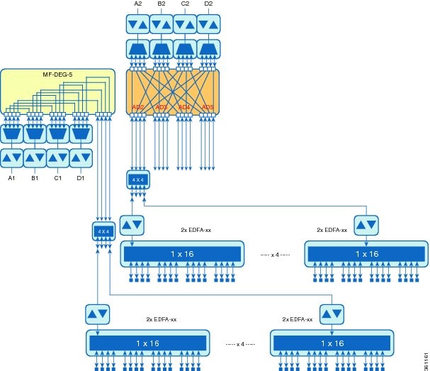
The following figure shows an example of a 4 degree omnidirectional terminal node up to 96 channels with MD-48-Odd/Even and 4x4-COFS.
The following figure shows an example of a 4 degree colorless omnidirectional terminal node up to 52 channels with 4x4-COFS.
- Terminal Node with 16-WXC-FS Up to 52 Channels - Cisco ONS 15454 M6
The following figure shows an example of a 4 degree colorless omnidirectional terminal node up to 128 channels with two independent add/drop stages.
OADM Node
An OADM node is a single node equipped with cards installed on both sides and at least one AD-xC-xx.x (or FLD-4-xx.x) card or one AD-xB-xx.x card (plus their related 4MD-xx.x cards) and two control cards. This configuration supports 32 channels. In an OADM node, channels can be added or dropped independently from each direction and then passed through the reflected bands of all OADMs in the DWDM node (called express path). They can also be passed through one OADM card to another OADM card without using a TDM ITU-T line card (called optical pass-through) if an external patchcord is installed.
Unlike express path, an optical pass-through channel can be converted later to an add/drop channel in an altered ring without affecting another channel. OADM amplifier placement and required card placement is determined by the Cisco TransportPlanner tool or your site plan.
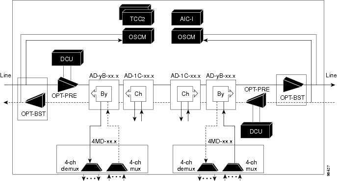
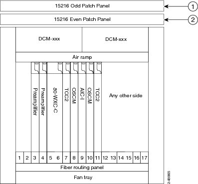
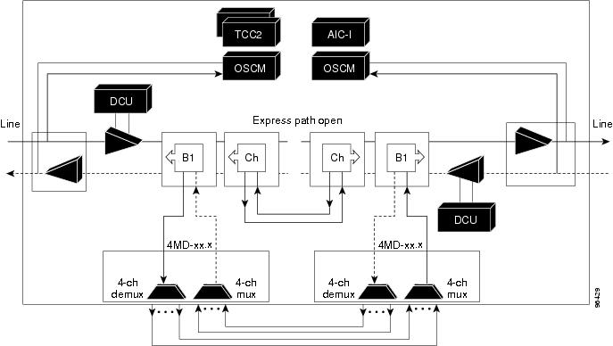
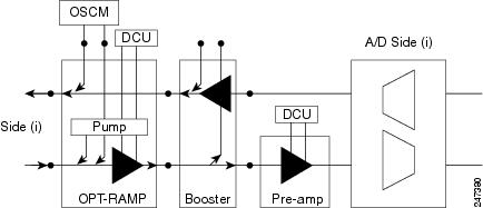
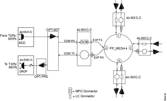
OADM nodes can be amplified or passive. In amplified OADMs, booster and preamplifier cards are installed on bode sides of the node. The following diagram shows an example of an amplified OADM node configuration. In addition, OADM nodes can be asymmetric. Amplifiers may be installed in one side, but not the other. Or preamplifiers may be installed in one side, and a booster in the other.
The following diagram shows an example of the channel flow on the amplified OADM node. Since the 32-wavelength plan is based on eight bands (each band contains four channels), optical adding and dropping can be performed at the band level and/or at the channel level (meaning individual channels can be dropped).
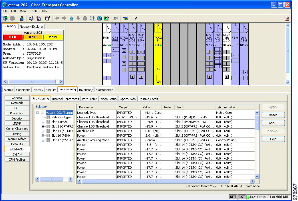
Specifying the number of circuits that are currently present on an amplifier that is receiving the power directly from the15216-FLD-4 passive units (in case of an OADM node with FLD-4 cards and when an APC domain is in passive state) enables an accurate calculation of the power gain on the amplified port. This also ensures that the amplifier works effectively when the number of circuits is lesser than the actual circuits provisioned (where APC does not run in those domains.
To provision the number of active circuits, in CTC go to the card view, click > tabs and enter the number of circuits currently active and then click Apply. Changing the value forces the system to recalculate the gain in order to obtain a more suitable output power.
You can manually provision the number of active circuits only if one of the following conditions are satisfied:
-
The amplified port that belongs to the APC domain is in passive state (an APC domain involving the OADM with 15216-FLD-4 passive modules and the APC is disabled).
-
The APC in the active domain where the APC is temporarily disabled by an alarm.
ROADM Node
A ROADM node adds and drops wavelengths without changing the physical fiber connections. A ROADM node is equipped with two control cards and one of the following combinations:
-
Two 32WSS cards and either, two 32DMX or 32DMX-O cards
-
Two 40-WSS-C or 40-WSS-CE cards and either, two 40-DMX-C or 40-DMX-CE cards
-
Two 40-SMR1-C cards and two 15216-MD-40-ODD, 15216-EF-40-ODD, or 15216-MD-48-ODD (ONS 15216 40 or 48-channel mux/demux) patch panels
-
Two 40-SMR1-C cards, two line amplifiers (OPT-BST, OPT-BST-E, OPT-AMP-C, or OPT-AMP-17C cards), two OPT-RAMP-C or OPT-RAMP-CE cards, and two 15216-MD-40-ODD, 15216-EF-40-ODD, or 15216-MD-48-ODD patch panels
-
Two 40-SMR2-C cards and two 15216-MD-40-ODD, 15216-EF-40-ODD, or 15216-MD-48-ODD patch panels
-
Two 80-WXC-C cards and two 15216-MD-40-ODD, 15216-EF-40-ODD, 15216-MD-48-ODD, 15216-MD-40-EVEN, 15216-EF-40-EVEN, or 15216-MD-48-EVEN patch panels
Note
Although it is recommended that you use the 15216-MD-40-ODD, 15216-EF-40-ODD, or 15216-MD-48-ODD patch panel along with the 40-SMR1-C and 40-SMR2-C cards, you can alternatively use the 40-MUX-C and 40-DMX-C cards instead of the 15216-MD-40-ODD, 15216-EF-40-ODD, or 15216-MD-48-ODD patch panel.
-
16-WXC-FS, MF-MPO-8LC, MF-4x4-COFS, MF-16AD-CFS, MF-DEG-5, MF-UPG-4, OPT-EDFA-xx, RAMAN-CTP (optional), RAMAN-COP, EDRA2-yy
Note |
Although not required, 32DMX-O can be used in a ROADM node. Cisco TransportPlanner automatically chooses the demultiplexer card that is best for the ROADM node based on the network requirements. |
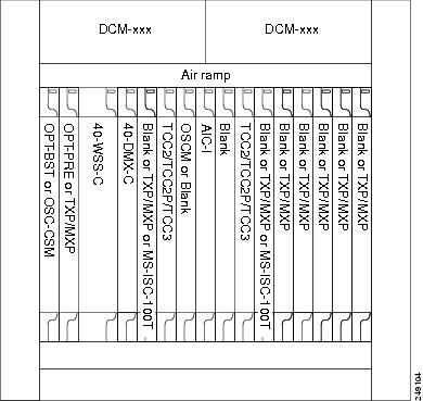
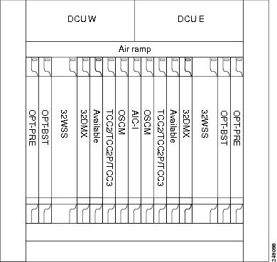
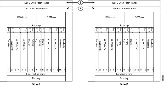
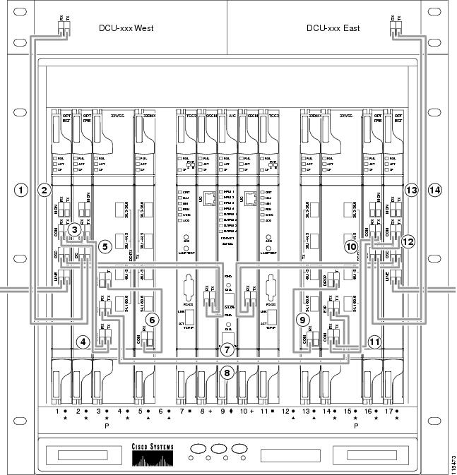
The following diagram shows an example of an amplified ROADM node configuration with 32DMX cards installed.
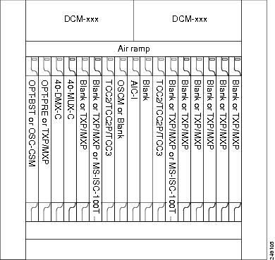
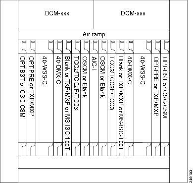
The following diagram shows an example of an amplified ROADM node configuration with 40-WSS-C cards installed.
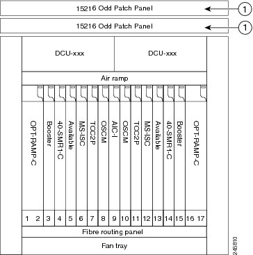
The following diagram shows an example of a ROADM node with 40-SMR1-C cards installed.

|
1 |
15216-MD-40-ODD, 15216-EF-40-ODD, or 15216-MD-48-ODD patch panel |
The following diagram shows an example of a ROADM node with 40-SMR1-C and booster amplifier cards installed.
|
1 |
15216-MD-40-ODD, 15216-EF-40-ODD, or 15216-MD-48-ODD patch panel |
Note |
When you use the 40-SMR1-C card along with a booster amplifier, the OSCM card must be connected to the booster amplifier. |
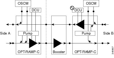
The following diagram shows an example of a ROADM node with 40-SMR1-C and OPT-RAMP-C cards installed.
|
1 |
15216-MD-40-ODD, 15216-EF-40-ODD, or 15216-MD-48-ODD patch panel |
The following diagram shows an example of a ROADM node with 40-SMR2-C cards installed.
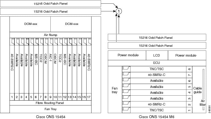
|
1 |
15216-MD-40-ODD, 15216-EF-40-ODD, or 15216-MD-48-ODD patch panel |
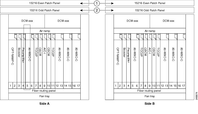
The following diagram shows an example of a colored two-degree ROADM node using 80-WXC-C cards with booster and preamplifier cards. The 80-WXC-C cards are inserted in Slots 3 and 14, and function in the bidirectional mode.
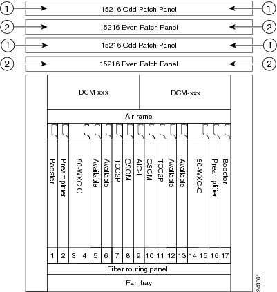
|
1 |
15216-MD-40-ODD, 15216-EF-40-ODD, or 15216-MD-48-ODD patch panel |
|
2 |
15216-MD-40-EVEN, 15216-EF-40-EVEN, or 15216-MD-48-EVEN patch panel |
The following diagram shows an example of an 80-channel colored two-degree ROADM node.
|
1 |
15216-MD-40-EVEN, 15216-EF-40-EVEN, or 15216-MD-48-EVEN patch panel |
|
2 |
15216-MD-40-ODD, 15216-EF-40-ODD, or 15216-MD-48-ODD patch panel |
The following diagram shows the layout of an 80-channel n-degree ROADM node with omni-directional side.
|
1 |
15216-MD-40-ODD, 15216-EF-40-ODD, or 15216-MD-48-ODD patch panel |
|
2 |
15216-MD-40-EVEN, 15216-EF-40-EVEN, or 15216-MD-48-EVEN patch panel |
The following diagram shows the layout of an 80-channel n-degree ROADM node with omni-directional side.
|
1 |
15216-MD-40-ODD, 15216-EF-40-ODD, or 15216-MD-48-ODD patch panel |
|
2 |
15216-MD-40-EVEN, 15216-EF-40-EVEN, or 15216-MD-48-EVEN patch panel |
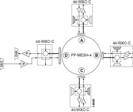
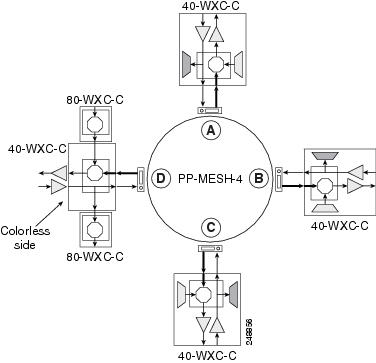
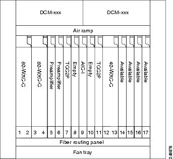
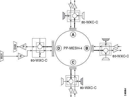
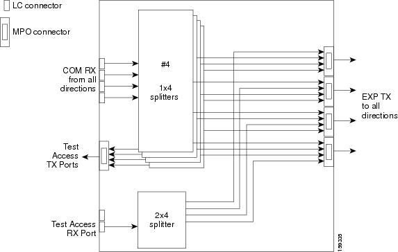
The following diagram shows the layout of a 40-channel n-degree ROADM node with a 40-WXC-C based colorless side.
The 80-WXC-C cards are connected to the ADD/DROP ports of the 40-WXC-C card and function as colorless multiplexer and demultiplexer units.
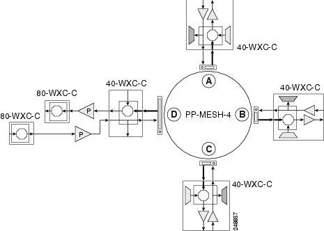
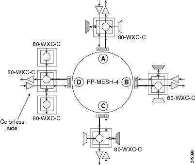
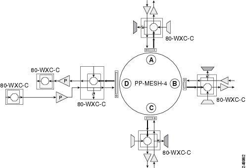
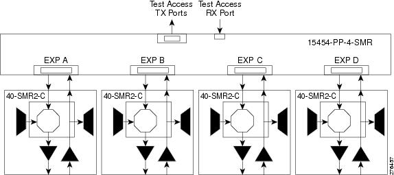
The following diagram shows the layout of a 40-channel four-degree ROADM node with a 40-SMR2-C based colorless side.
|
1 |
15216-MD-40-ODD, 15216-EF-40-ODD, or 15216-MD-48-ODD patch panel |
The 80WXC-C (multiplexer) card is inserted in Slot 3 and the 80-WXC-C (demultiplexer) card is inserted in Slot 5. The 80-WXC-C cards are connected to the ADD/DROP ports of the 40-SMR2-C card and function as the colorless multiplexer and demultiplexer units.
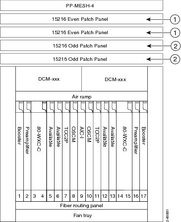
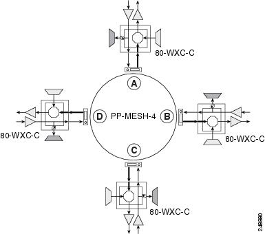
The following diagram shows the layout for an 80-channel colorless ROADM node.
|
1 |
15216-MD-40-EVEN, 15216-EF-40-EVEN, or 15216-MD-48-EVEN patch panel |
|
2 |
15216-MD-40-ODD, 15216-EF-40-ODD, or 15216-MD-48-ODD patch panel |
An 80 channel colorless two-degree ROADM node requires the following cards: 80-WXC-C, 15216-MD-40-ODD, 15216-EF-40-ODD, 15216-MD-48-ODD, 15216-MD-40-EVEN, 15216-EF-40-EVEN, 15216-MD-48-EVEN, preamplifiers, and boosters.
The 80-WXC-C cards can be used at two levels; level1 (L1) and level2 (L2).
The L1 80WXC-C (multiplexer) card is inserted in Slot 3 and the L1 80-WXC-C (demultiplexer) card is inserted in Slot 5. The L2 80WXC-C (multiplexer) card is inserted in Slot 12 and the L2 80-WXC-C (demultiplexer) card is inserted in Slot 14.
The following diagram shows an example of the optical signal flow in an 80-channel colorless two-degree ROADM node from Side A to Side B using 80-WXC-C cards. The optical signal flow from Side B to Side A follows an identical path.
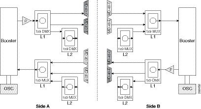
|
1 |
The booster on Side A receives the composite optical signal. It separates the optical service channel from the optical payload and sends the payload to the preamplifier on Side A. |
|
2 |
The preamplifier compensates for chromatic dispersion, amplifies the optical payload and sends it to the L1 80-WXC-C card (demultiplexer). |
|
3 |
Up to eight colorless ports are available on the L1 80-WXC-C card if no colored wavelength is terminated. The two EAD ports are connected to 15216-MD-40-ODD, 15216-EF-40-ODD, 15216-MD-48-ODD, 15216-MD-40-EVEN, 15216-EF-40-EVEN, or 15216-MD-48-EVEN units where the colored odd and even wavelengths are dropped. |
|
4 |
The L1-80-WXC-C card on Side B sends the composite signal to the booster on Side B. |
|
5 |
The booster on Side B receives the composite optical signal, adds the optical service channel to the optical payload and sends it to the transmission line. |
|
6 |
It is possible to configure more colorless ports by cascading the 80-WXC-C cards at two levels. For example, to get 14 colorless ports connect one of the EAD ports of the L1 80-WXC-C card to another 80-WXC-C cards at level 2. There are five colorless ports on the L1 80-WXC-C card and nine colorless ports on the L2 80-WXC-C card. To achieve an 80 channel colorless configuration, connect nine L2 80-WXC-C cards to the nine EAD ports of the L1 80-WXC-C card. |
The following diagram shows the layout for an 80-channel colorless ROADM node with OPT-RAMP-C cards.
|
1 |
15216-MD-40-EVEN, 15216-EF-40-EVEN, or 15216-MD-48-EVEN patch panel |
|
2 |
15216-MD-40-ODD, 15216-EF-40-ODD, or 15216-MD-48-ODD patch panel |
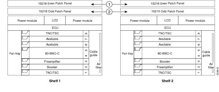
The following diagram shows an example of an ONS 15454 M6 80-channel two degree colorless ROADM node.
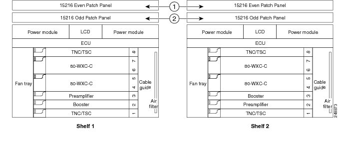
|
1 |
15216-MD-40-EVEN, 15216-EF-40-EVEN, or 15216-MD-48-EVEN patch panel |
|
2 |
15216-MD-40-ODD, 15216-EF-40-ODD, or 15216-MD-48-ODD patch panel |
The L1 80WXC-C (multiplexer) card is inserted in Slot 4 and the L1 80-WXC-C (demultiplexer) is inserted in Slot 6. The L2 80WXC-C (multiplexer) card is inserted in Slot 2 and the L2 80-WXC-C (demultiplexer) is inserted in Slot 4.
An example of a ROADM optical signal flow from Side A to Side B using the 32WSS or 40-WSS-C card is shown. The optical signal flow from Side B to Side A follows an identical path through the Side B OSC-CSM and32WSS or 40-WSS-C cards. In this example, OSC-CSM cards are installed, hence OPT-BSTs are not needed.
The following diagram shows an example of an ONS 15454 M6 80-channel ROADM node with RAMAN-CTP cards installed.
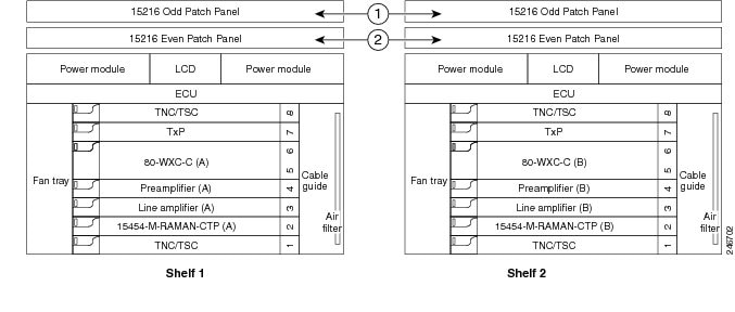
|
1 |
15216-MD-40-ODD, 15216-EF-40-ODD, or 15216-MD-48-ODD patch panel |
|
2 |
15216-MD-40-EVEN, 15216-EF-40-EVEN, or 15216-MD-48-EVEN patch panel |
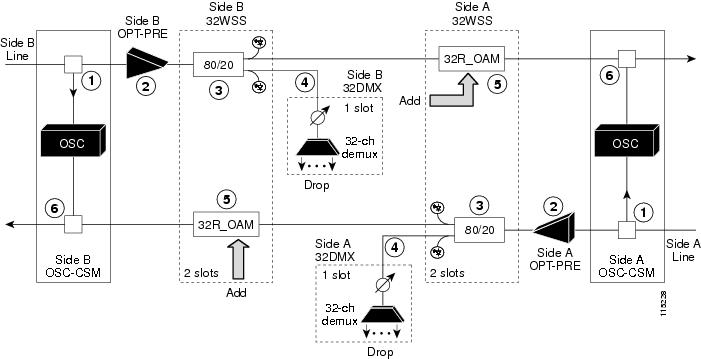
|
1 |
The OSC-CSM receives the optical signal. It separates the optical service channel from the optical payload and sends the payload to the OPT-PRE module. |
|
2 |
The OPT-PRE compensates for chromatic dispersion, amplifies the optical payload, and sends it to the 32WSS or 40-WSS-C/40-WSS-CE. |
|
3 |
The 32WSS or 40-WSS-C/40-WSS-CE splits the signal into two components. The 80 percent component is sent to the DROP-TX port and the 20 percent component is sent to the EXP-TX port. |
|
4 |
The drop component goes to the 32DMX card or 40-DMX-C/40-DMX-CE card where it is demultiplexed and dropped. |
|
5 |
The express wavelength aggregate signal goes to the 32WSS or 40-WSS-C/40-WSS-CE on the other side where it is demultiplexed. Channels are stopped or forwarded based upon their switch states. Forwarded wavelengths are merged with those coming from the ADD path and sent to the OSC-CSM module. |
|
6 |
The OSC-CSM combines the multiplexed payload with the OSC and sends the signal out the transmission line. |
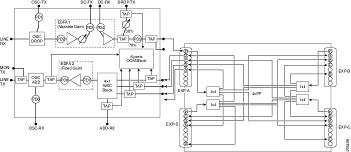
The following diagram shows an example of an ROADM optical signal flow from Side A to Side B using the 40-SMR1-C card. The optical signal flow from Side B to Side A follows an identical path through the Side B booster and 40-SMR1-C card.
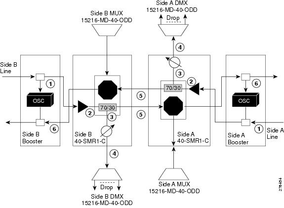
|
1 |
The booster receives the optical signal. It separates the optical service channel from the optical payload and sends the payload to the preamplifier module within the 40-SMR1-C card. |
|
2 |
The preamplifier module compensates for chromatic dispersion, amplifies the optical payload, and sends it to the 70/30 splitter within the 40-SMR1-C card. |
|
3 |
The 70/30 splitter splits the signal into two components. The 70 percent component is sent to the DROP-TX port and the 30 percent component is sent to the EXP-TX port. |
|
4 |
The drop component goes to the 15216-MD-40-ODD, 15216-EF-40-ODD, or 15216-MD-48-ODD unit where it is demultiplexed and dropped. |
|
5 |
The express wavelength aggregate signal goes to the 40-SMR1-C card on the other side where it is demultiplexed. Channels are stopped or forwarded based upon their switch states. Forwarded wavelengths are merged with those coming from the ADD path and sent to the booster module. |
|
6 |
The booster combines the multiplexed payload with the OSC, amplifies it, and sends the signal out the transmission line. |
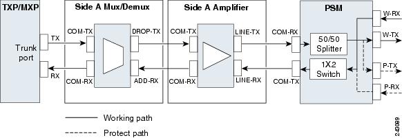
The following diagram shows a colored directional A/D ROADM configuration with MD-48 units connected to the UPG-RX or TX port of each 16-WXC-FS card.
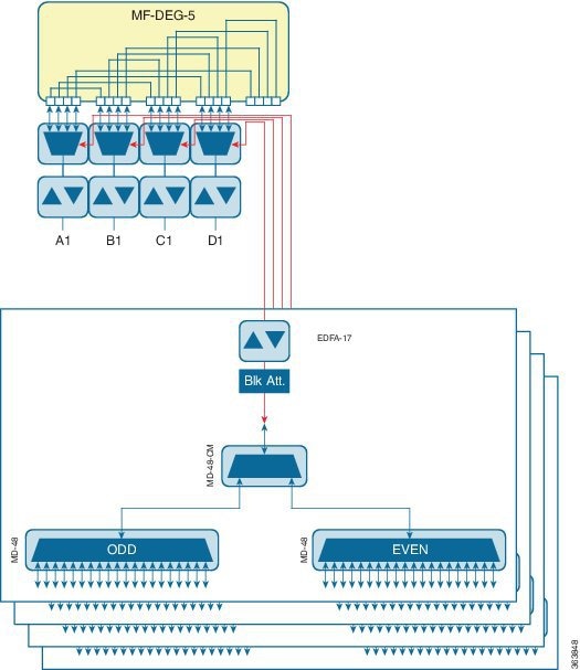
This configuration is used for a directional colored A/D ROADM configuration with more than 12 degrees and for any ROADM configuration that requires PSM-OCH protection. The amplifiers on the drop path are EDFA-17 cards and they work in constant Gain mode with a reference per-channel output power of 0 dBm and are configured in the PRE mode. The 16-WXC-FS card sets the input power of the EDFA-17 cards to obtain a typical gain of 10 dB. A 5 dB bulk attenuator is used to lower the output power of the EDFA -17 cards before it reaches the receiving channels.
The following diagram displays a colored directional 48-channel 100 GHz A/D ROADM configuration.
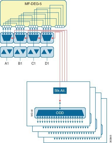
If the network uses only 100GHz channels (both odd and even grids), the MD-48-CM unit is not required and the channels can be inserted through the MD-48 units connected to the UPG TX or RX ports of each 16-WXC-FS card. A/D amplifiers are not required in this configuration. A 3 dB attenuator is recommended on the Add path between the MD-48 COM-TX port and the 16-WXC-FS UPG-RX port to lower the VOA setting requested to 16-WXC-FS card. This configuration is used for all degrees of ROADM (2 to 16) and it supports PSM-OCH protection on the terminated channels.
The following diagram displays a colored omnidirectional 48-channel 100 GHz A/D 4-degree ROADM configuration.
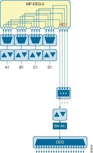
If the network uses only 100GHz channels (both odd and even grids), the MD-48-CM unit is not required on the omnidirectional colored A/D stages. Two EDFA-xx cards are used as additional amplifiers on the MD stage. These amplifiers are configured as PRE and they work in the constant Gain mode. On the Add path an EDFA-17 card is used with a reference per-channel output power of 0 dBm. A 5 dB bulk attenuator is used at the EDFA-17 card input to correctly set the amplifier gain and obtain a typical gain of 8 dB. On the drop path an EDFA-17 card is used with a reference per-channel output power of -2 dBm. The 16-WXC-FS card sets the EDFA input power so that a typical gain of 13 dB is obtained, while at the EDFA-17 output a 5 dB bulk attenuator is used to lower the power of all the received channels.
The following diagram displays a colored omnidirectional 48-channel 100 GHz A/D ROADM configuration with more than 4 degrees.
Two EDFA-xx cards are used as additional amplifiers on the MD stage. These amplifiers are configured as PRE and they work in the constant Gain mode. On the Add path an EDFA-17 card is used with a reference per-channel output power of 0 dBm. A 5 dB bulk attenuator is used at the EDFA-17 card input to correctly set the amplifier gain and obtain a typical gain of 8 dB. On the drop path an EDFA-24 card with a target gain of 15 dB is used with a reference per-channel output power of -3 dBm. A 5 dB bulk attenuator is used to lower the power of all the received channels.
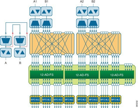
The following figure shows a two degree contentionless ROADM node configuration using the SMR9 FS and 12-AD-FS cards.
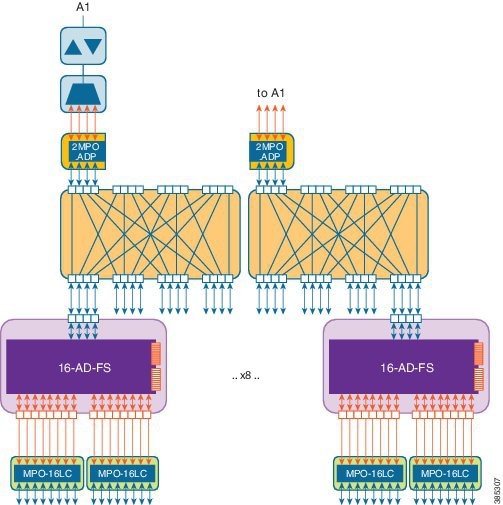
The following figure shows a terminal ROADM node configuration using the SMR20 FS and 16-AD-FS cards.
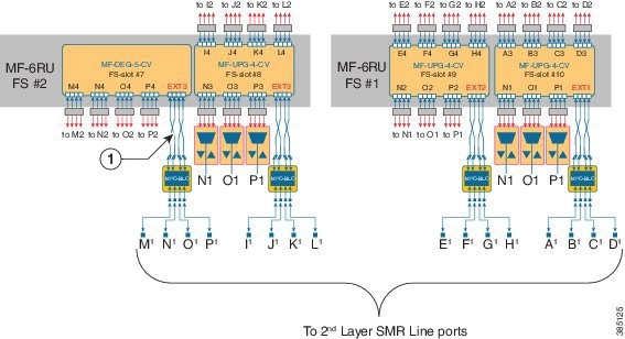
ROADM configuration with SMR20 FS in the omnidirectional side
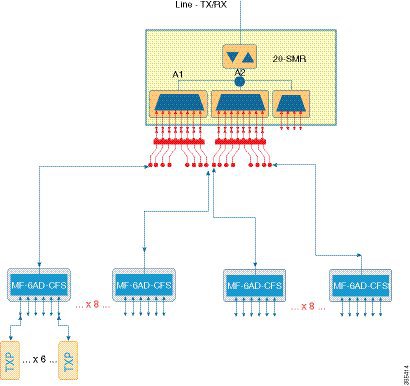
Omnidirectional colorless A/D with high channel count provides A/D capability for 96 channels.
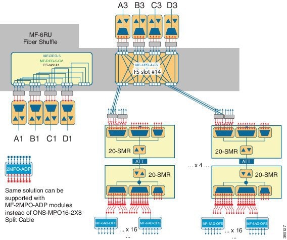
This is a non-contentionless colorless configuration.
Here, two SMR20 FS units are used. The first unit routes traffic to/from different line directions, while the second unit is used as a port-replicator to feed a set of sixteen units of MF-6AD-CFS passive A/D modules. The SMR20 is in the omnidirectional node. The cascaded SMR units are connected using an attenuator as the amplifier input signal is double in the first SMR. The configuration can have 16 A/D per port and a maximum of sixteen passive MF-6AD-CFS cards, where each passive card can add six wavelengths.
Note |
Instead of SMR20 FS cards, SMR20 FS CV can also be used. |
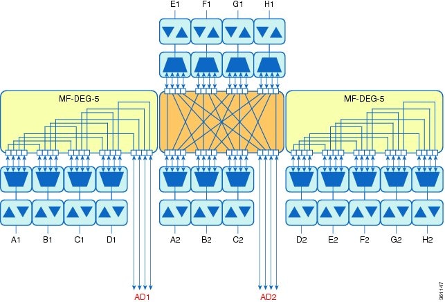
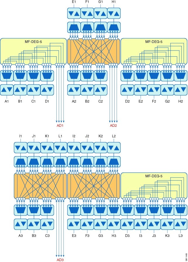
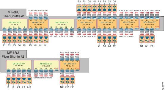
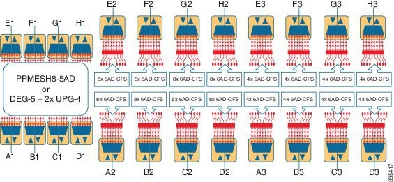
ROADM configurations with extended A/D capability with cascading SMR20 FS
In a two-layered SMR20 FS units' array, the second layer of SMR20 FS units are subtended on the first layer, using an extension port available on the main PP-MESH. The second Layer SMR20 FS is used to increase the node A/D capacity. One port from SMR (layer 1A) is cascaded to another SMR (layer 2A). This gives more drop capability. Circuits in layer 2 can be added/ dropped only. Layer 2A and 2B are not connected. Express connection is possible only in layer 1. The amplifiers in layer 1 are in gain controller mode; amplifiers in layer 2 are in fixed gain mode.
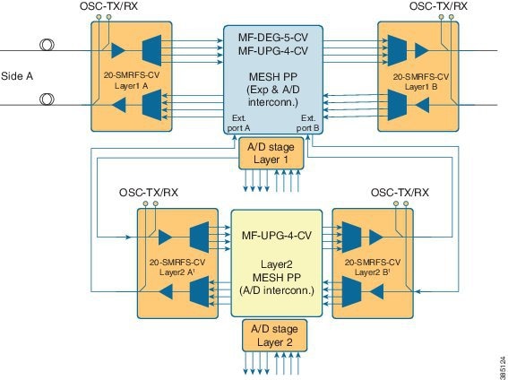
Note |
Instead of SMR20 FS CV cards, SMR20 FS can also be used. |
Optical connections from layer 1 and layer 2 A/D are between the MPO-8 extension ports of the mesh patch-panel passive modules and the LC line ports of the SMR20 FS card. The physical optical adaptations of these interconnections are performed with a MF-MPO-8LC passive card with a special MPO-to-MPO cross cable (ONS-12MPO-XMPO-x) as shown in the following figures, for different ROADM sizes.
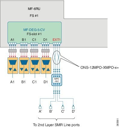
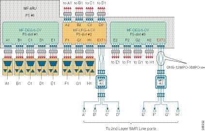
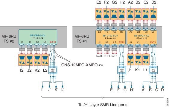
|
1 |
MPO crossed cable |
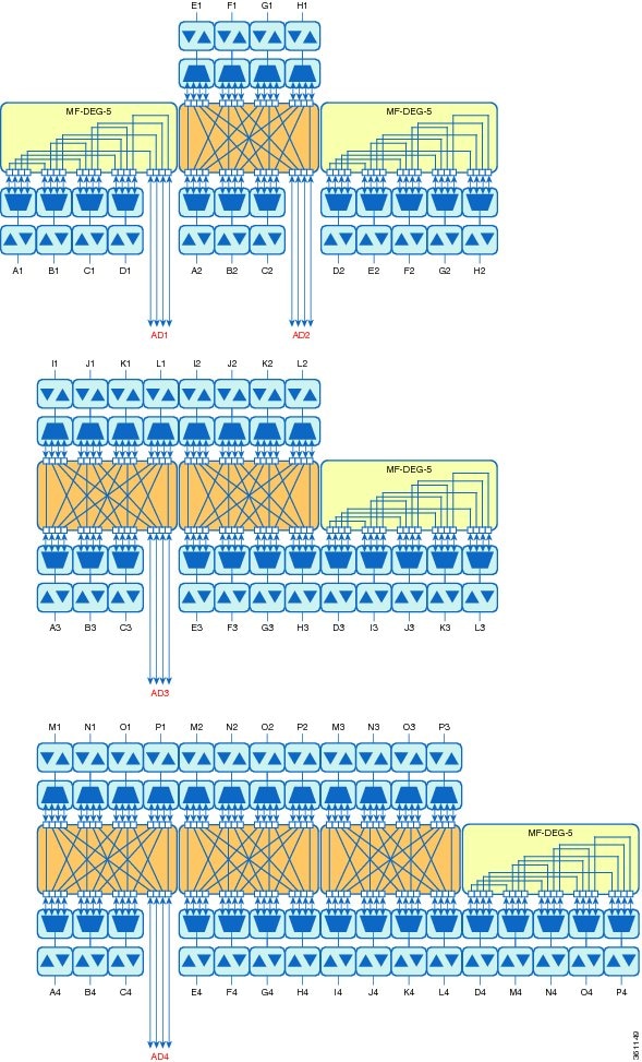
Contentionless ROADM configuration for 16 degrees
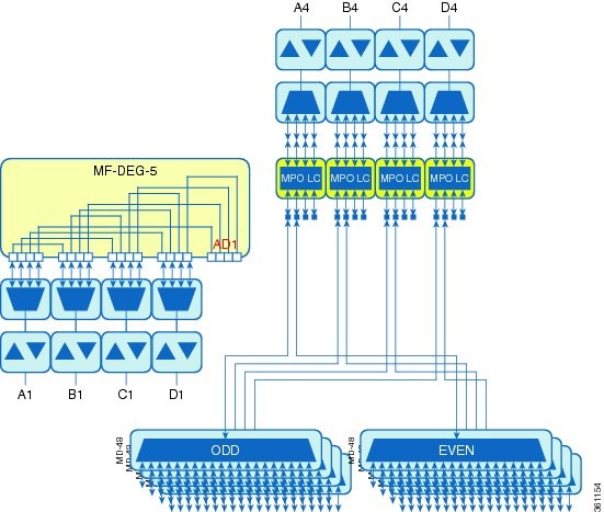
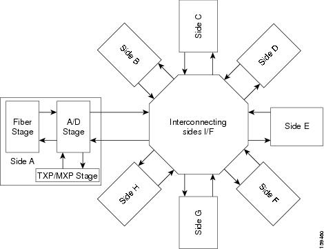
The following figure represents the connections between the omnidirectional side and all the line sides (contentionless A/D stage).
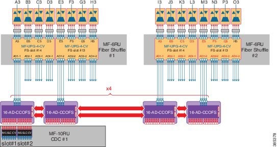
One node can have up to 16 sides (A to P). Four 16-port A/D cards are cascaded in the omnidirectional side. This configuration allows to have a 16 degree node, with at least one contentionless, colorless omnidirectional side by cascading four 16 AD-CCOFS cards.
ROADM Configurations with MF-6AD-CFS
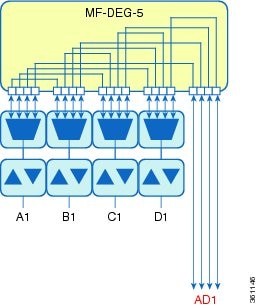
From Release 10.6.2, a new colorless, directional A/D stage is available using the passive A/D module, MF-6AD-CFS. A set of MF-6AD-CFS passive splitter/coupler modules are connected to the SMR-20 EXP-TX/RX ports to obtain a colorless (and gridless) directional A/D stage. The interconnection can be done either with the break-out cable, ONS-MPO-16-LC2= or with the adapter module, MF-MPO-16LC. This A/D stage provides modular A/D capability up to 96 channels (with steps of 6 channels) that can be used to insert/extract colorless channels to or from a specific ROADM direction (side). This A/D stage works only with coherent trunk interfaces.
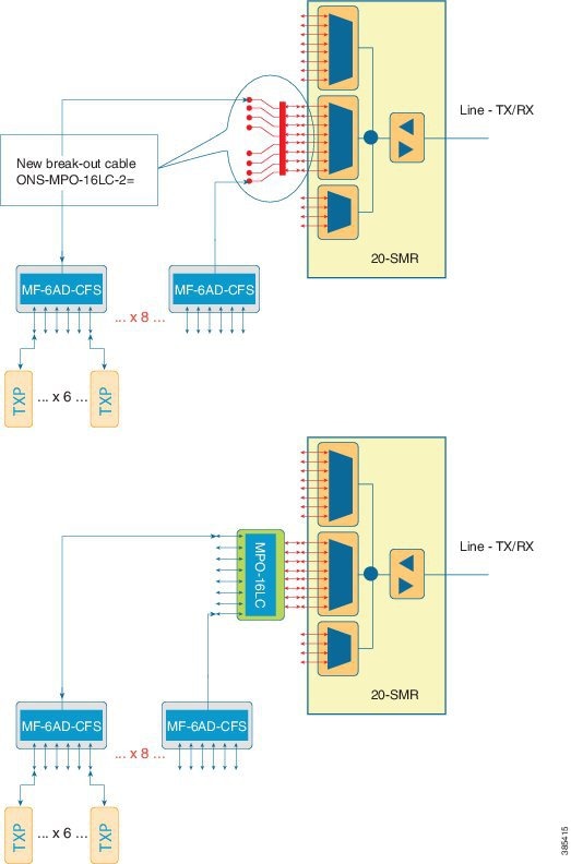
The table below, defines the interconnection between 20-SMR and the different MF-6AD-CFS passive modules with the ONS-MPO-16LC-2 cable.
|
SMR Signal |
LC Label |
MF-6AD-CFS |
Port |
|---|---|---|---|
|
EXP-TX-x-1 |
1 |
1 |
COM-RX |
|
EXP-RX-x-9 |
9 |
1 |
COM-TX |
|
EXP-TX-x-2 |
2 |
2 |
COM-RX |
|
EXP-RX-x-10 |
10 |
2 |
COM-TX |
|
EXP-TX-x-3 |
3 |
3 |
COM-RX |
|
EXP-RX-x-11 |
11 |
3 |
COM-TX |
|
EXP-TX-x-4 |
4 |
4 |
COM-RX |
|
EXP-RX-x-12 |
12 |
4 |
COM-TX |
|
EXP-TX-x-5 |
5 |
5 |
COM-RX |
|
EXP-RX-x-13 |
13 |
5 |
COM-TX |
|
EXP-TX-x-6 |
6 |
6 |
COM-RX |
|
EXP-RX-x-14 |
14 |
6 |
COM-TX |
|
EXP-TX-x-7 |
7 |
7 |
COM-RX |
|
EXP-RX-x-15 |
15 |
7 |
COM-TX |
|
EXP-TX-x-8 |
8 |
8 |
COM-RX |
|
EXP-RX-x-16 |
16 |
8 |
COM-TX |

ROADM Split Nodes
Hub Node
A hub node is a single ONS 15454 node equipped with two control cards and one of the following combinations:
-
Two 32MUX-O cards and two 32DMX-O or 32DMX cards
-
Two 32WSS cards and two 32DMX or 32DMX-O cards
-
Two 40-WSS-C or 40-WSS-CE cards and two 40-DMX-C or 40DMX-CE cards
-
Two 40-SMR1-C and two 15216-MD-40-ODD, 15216-EF-40-ODD, or 15216-MD-48-ODD (ONS 15216 40 or 48-channel mux/demux patch panel)
-
Two 40-SMR2-C and two 15216-MD-40-ODD, 15216-EF-40-ODD, or 15216-MD-48-ODD
Note
Although it is recommended that you use the 15216-MD-40-ODD, 15216-EF-40-ODD, or 15216-MD-48-ODD patch panel along with the 40-SMR1-C and 40-SMR2-C cards, you can alternatively use the 40-MUX-C and 40-DMX-C cards instead of the 15216-MD-40-ODD, 15216-EF-40-ODD, or 15216-MD-48-ODD patch panel.
Note
The configuration for a hub node using 40-SMR1-C or 40-SMR2-C cards is identical to the ROADM node, except that there is no patchcord connecting the two 40-SMR1-C or 40-SMR2-C cards. For more details on the ROADM node configuration, see the ROADM Node.
Note
The 32WSS/40-WSS-C/40-WSS-CE and 32DMX/32DMX-L/40-DMX-C/ 40-DMX-CE cards are normally installed in ROADM nodes, but they can also be installed in hub and terminal nodes. If the cards are installed in a hub node, the 32WSS/32WSS-L/ 40-WSS-C/40-WSS-CE express ports (EXP RX and EXP TX) are not cabled.
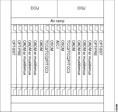
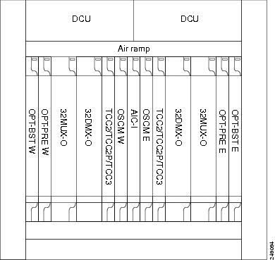
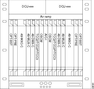
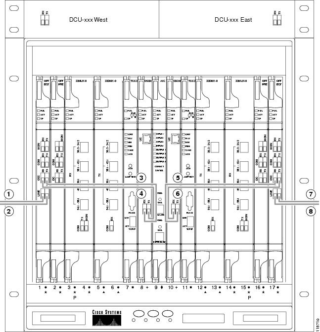
A dispersion compensation unit (DCU) can also be added, if necessary. The following diagram shows a hub node configuration with 32MUX-O and 32DMX-O cards installed.
The following diagram shows a 40-channel hub node configuration with 40-WSS-C cards installed.

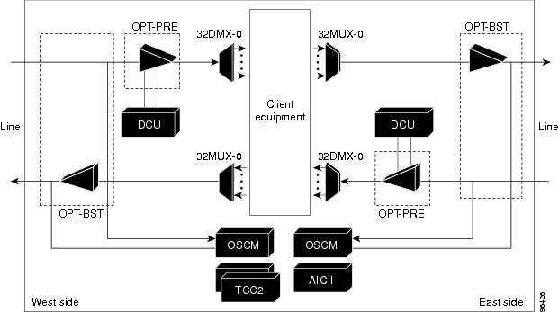
The following diagram shows the channel flow for a hub node. Up to 32 channels from the client ports are multiplexed and equalized onto one fiber. Then, multiplexed channels are transmitted to the OPT-BST amplifier. The OPT-BST output is combined with an output signal from the OSCM card and transmitted to the other side. Received signals are divided between the OSCM card and an OPT-PRE card. Dispersion compensation is applied to the signal received by the OPT-PRE amplifier, and it is then sent to the 32DMX-O card, which demultiplexes and attenuates the input signal.
Anti-ASE Node
In a mesh ring network, the ONS 15454 requires a node configuration that prevents ASE accumulation and lasing. An anti-ASE node can be created by configuring a hub node or an OADM node with some modifications. No channels can travel through the express path, but they can be demultiplexed and dropped at the channel level on one side and added and multiplexed on the other side.
The hub node is the preferred node configuration when some channels are connected in pass-through mode. For rings that require a limited number of channels, combine AD-xB-xx.x and 4MD-xx.x cards, or cascade AD-xC-xx.x cards.
The following diagram shows an anti-ASE node that uses all wavelengths in the pass-through mode. Use Cisco TransportPlanner to determine the best configuration for anti-ASE nodes.
Line Amplifier Node
A line amplifier node is a single ONS 15454 node that is used to amplify the optical signal in long spans. The line amplifier node can be equipped with one of the following sets of cards:
-
Two OPT-PRE cards, two OPT-BST cards, and two OSCM cards
-
Two OPT-PRE cards and two OSC-CSM cards
-
Two OPT-AMP-17-C cards and two OSCM cards
-
Two OPT-AMP-C cards and two OSCM cards
Attenuators might also be required between each preamplifier and OPT-BST amplifier to match the optical input power value and to maintain the amplifier gain tilt value.
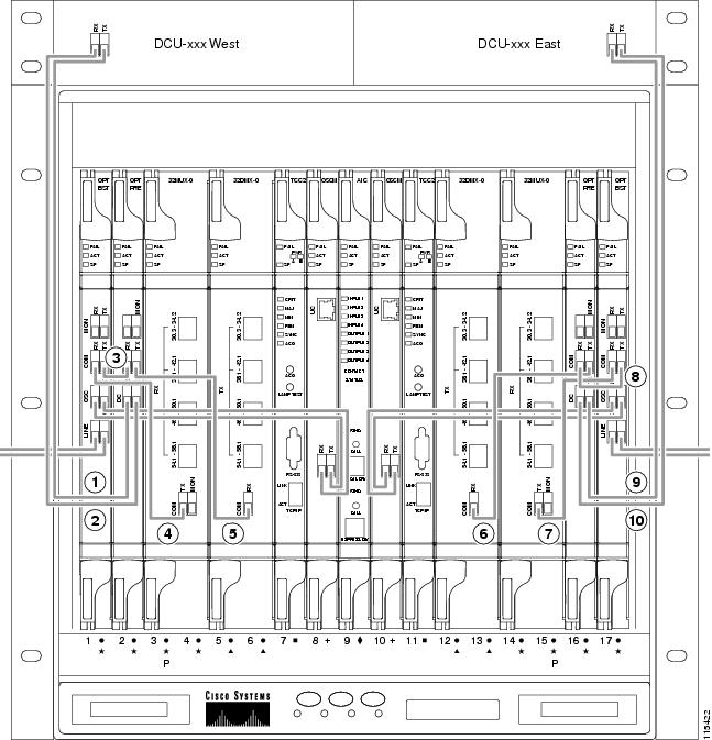
Two OSCM cards are connected to the OPT-BST cards to multiplex the OSC signal with the pass-though channels. If the node does not contain a booster card, OSC-CSM cards must be installed instead of OSCM cards. The following diagram shows an example of a line amplifier node configuration using OPT-BST, OPT-PRE, and OSCM cards.
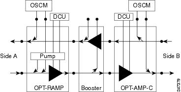
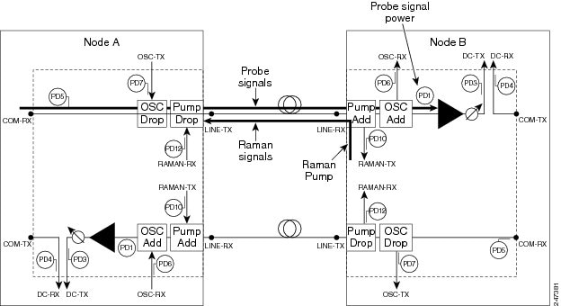
The line amplifier can be equipped with OPT-RAMP-C or OPT-RAMP-CE cards to achieve in fiber amplification. The following diagram shows an example of a line amplifier node with Raman amplification using OPT-RAMP-C cards.
A node layout equipped with OPT-RAMP-C or OPT-RAMP-CE cards without post-amplifiers is used when post-amplification of the optical signal is not required.
This layout is used in the following scenarios:
-
The fiber is non-linear with high Raman gain (12.5 dB)
-
The span length is 13 to 22 dB
There are three node layouts without post-amplifiers:
-
Line amplifier node equipped with OPT-RAMP-C or OPT-RAMP-CE cards on Side A and Side B.
-
Line amplifier node equipped with OPT-RAMP-C or OPT-RAMP-CE and booster cards on Side A and OPT-RAMP-C or OPT-RAMP-CE cards on Side B and vice-versa.
-
Line amplifier node equipped with OPT-RAMP-C or OPT-RAMP-CE and booster cards on Side A and OSC-CSM cards on Side B and vice-versa.
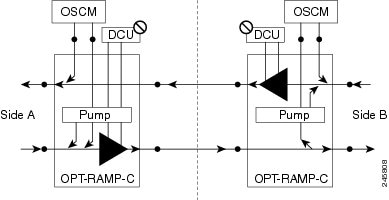
The following figure shows an example of a line amplifier node with OPT-RAMP-C cards on Side A and Side B.
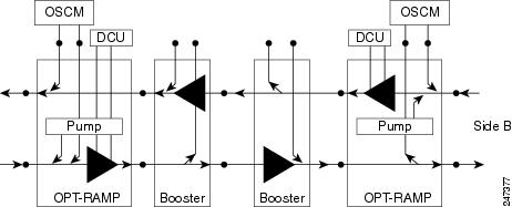
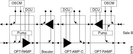
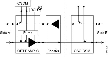
The following diagram shows an example of a line amplifier node with a standard Raman configuration (OPT-RAMP-C or OPT-RAMP-CE and booster cards) on Side A and a Raman only configuration (OPT-RAMP-C or OPT-RAMP-CE cards) on Side B.

The following diagram shows an example of a line amplifier node with a standard Raman configuration (OPT-RAMP-C or OPT-RAMP-CE and booster cards) on Side A and an OSC-CSM configuration on Side B.
OSC Regeneration Node
The OSC regeneration node is added to the DWDM networks for two purposes:
-
To electrically regenerate the OSC channel whenever the span links are 37 dB or longer and payload amplification and add/drop capabilities are not present. Cisco TransportPlanner places an OSC regeneration node in spans longer than 37 dB. The span between the OSC regeneration node and the next DWDM network site cannot be longer than 31 dB.
-
To add data communications network (DCN) capability wherever needed within the network.
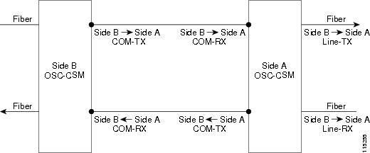
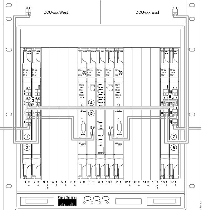
OSC regeneration nodes require two OSC-CSM cards, as shown in the following figure. The cards are installed in each side of the shelf.
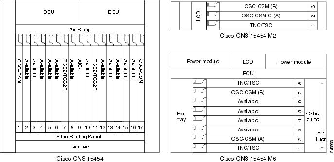
The following figure shows the OSC regeneration line node signal flow.


 Feedback