Creating Optical Channel Circuits and Provisionable Patchcords

This chapter explains the Cisco ONS 15454 dense wavelength division multiplexing (DWDM) optical channel (OCH) circuit types and virtual patchcords that can be provisioned on the Cisco ONS 15454. Circuit types include the OCH client connection (OCHCC), the OCH trail, and the OCH network connection (OCHNC). Virtual patchcords include internal patchcords and provisionable (external) patchcords (PPCs). This chapter also describes End-to-End SVLAN Circuit that can be created between GE_XP, 10GE_XP, GE_XPE, or 10GE_XPE cards.

This chapter explains how to create Cisco ONS 15454 dense wavelength division multiplexing (DWDM) optical channel client connections (OCHCCs), optical channel network connections (OCHNCs), optical trail circuits, and STS circuits. The chapter also tells you how to create provisionable patchcords, upgrade OCHNCs to OCHCCs, manage SVLANs for GE_XP, 10GE_XP, GE_XPE, and 10GE_XPE cards, and manage overhead circuits.


Note


Unless otherwise specified, “ONS 15454" refers to both ANSI and ETSI shelf assemblies.


Note


In this chapter, “RAMAN-CTP” refers to the 15454-M-RAMAN-CTP card. “RAMAN-COP” refers to the 15454-M-RAMAN-COP card.


Note


In this chapter, the “NFV view” refers to the “DWDM Network Functional View (NFV)”. The “GMPLS view” refers to the “DWDM Network Functional View (GMPLS)”.


Note


In this chapter, “100G-LC-C card” refers to the 15454-M-100G-LC-C card. “10x10G-LC” refers to the 15454-M-10x10G-LC card. “CFP-LC” refers to the 15454-M-CFP-LC card.


Optical Channel Circuits

The DWDM optical circuits provide end-to-end connectivity using three OCH circuit types:

  • Optical Channel Network Connections (OCHNC)

  • Optical Channel Client Connections (OCHCC)

  • Optical Channel Trails (OCH Trails)

A graphical representation of OCH circuits is shown in the following figure.

Figure 1. Optical Channel Circuits

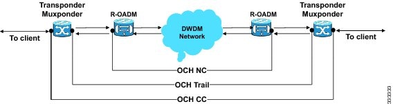
When the user selects a circuit in the Circuits tab, the corresponding circuit in the network map is highlighted. When the user deselects a circuit in the Circuits tab, the corresponding circuit in the network map is also deselected.

When the transponders are in non-co-located nodes and there is an optical loss of signal on the filter card for a particular wavelength, the circuit for that particular wavelength does not go down to OOS state.

OCHNC Circuits

OCHNC circuits establish connectivity between two optical nodes on a specified C-band wavelength. The connection is made through the ports present on the wavelength selective switches, multiplexers, demultiplexer, and add/drop cards. In an OCHNC circuit, the wavelength from a source OCH port ingresses to a DWDM system and then egresses from the DWDM system to the destination OCH port. The source and destination OCH port details are listed in the following table.

Table 1. OCHNC Ports

Card

Source Ports

Destination Ports

32WSS

32WSS-L

40-WSS-C

40-WSS-CE

ADD-RX

32MUX-O

40-MUX-C

CHAN-RX

32DMX-O

32DMX

32DMX-L

40-DMX-C

40-DMX-CE

CHAN-TX

4MD

AD-1C-xx.x

AD-4C-xx.x

CHAN-RX

CHAN-TX

40-SMR1-C

40-SMR2-C

ADD-RX

DROP-TX

15216-MD-40-ODD

15216-MD-40-EVEN

CHAN-RX

CHAN-TX

15216-EF-40-ODD

15216-EF-40-EVEN

CHAN-RX

CHAN-TX

15216-MD-48-ODD

15216-MD-48-EVEN

CHAN-RX

CHAN-TX

15216-FLD-4

CHAN-RX

CHAN-TX


Note


When the 40-SMR1-C or 40-SMR2-C card operates along with the 15216-MD-40-ODD, 15216-EF-40-ODD, or 15216-MD-48-ODD (ONS 15216 40 or 48-channel mux/demux) patch panel, the OCH ports on the patch panel are the endpoints of the OCHNC circuit. 

When the 40-SMR1-C or 40-SMR2-C card operates along with the 40-MUX-C and 40-DMX-C cards, the endpoints of the OCHNC circuit are on the MUX/DMX cards.


OCHCC Circuits

OCHCC circuits extend the OCHNC to create an optical connection from the source client port to the destination client port of the TXP/MXP cards. An OCHCC circuit represents the actual end-to-end client service passing through the DWDM system.

Each OCHCC circuit is associated to a pair of client or trunk ports on the transponder (TXP), muxponder (MXP), GE_XP (in layer-1 DWDM mode), 10GE_XP (in layer-1 DWDM mode), or ITU-T line card.

The OCHCCs can manage splitter protection as a single protected circuit. However, for the Y-Cable protection, two OCHCC circuits and two protection groups are required.

OCH Trail Circuits

OCH trail circuits transport the OCHCCs. The OCH trail circuit creates an optical connection from the source trunk port to the destination trunk port of the Transponder (TXP), Muxponder (MXP), GE_XP, 10GE_XP, or ITU-T line card. The OCH trail represents the common connection between the two cards, over which all the client OCHCC circuits, SVLAN circuits or STS circuits are carried.

Once an OCHCC is created, a corresponding OCH Trail is automatically created. If the OCHCC is created between two TXP, MXP, GE_XP, or 10GE_XP cards, two circuits are created in the CTC. These are:

One OCHCC (at client port endpoints)

One OCH trail (at trunk port endpoints)

If the OCHCC is created between two TXPP or two MXPP cards, three circuits are created in the CTC. These are:

  • One OCHCC (at client port endpoints)

  • Two OCH Trails (at trunk port endpoints)
One for the working and other for the protect trunk.


    Note


    On a TXP, MXP, and GE_XP card (in layer 1 DWDM mode), additional OCHCC circuits are created over the same OCH trail.


    Note


    On a TXP, MXP, GE_XP (in layer 1 DWDM mode), and 10GE_XP (in layer 1 DWDM mode) card, the OCH trail cannot be created independently, and is created along with the first OCHCC creation on the card. However, on a GE_XP card (in layer-2 DWDM mode), 10GE_XP card (in layer-2 DWDM mode), and ADM_10G card, an OCH trail can be created between the trunk ports for the upper layer circuits (SVLAN in GE_XP/10GE_XP and STS in ADM_10G). No OCHCC is supported in these cases.


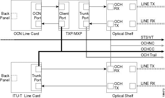
If the OCHCC is created between two ITU-T line cards, only one trunk port belongs to the OCHCC at each end of the circuit. The following table lists the ports that can be OCHCC and OCH trail endpoints.

Table 2. OCHCC and OCH Trail Ports

Card

OCHCC

OCH Trail

TXPs

MXPs

GE_XP

10GE_XP

ADM-10G

Any client port

Any trunk port

ITU-T line cards:

  • OC48/STM64 EH

  • OC192 SR/STM64

  • MRC-12

  • MRC-2.5-12

  • MRC-2.5G-4

Any trunk port

Any trunk port

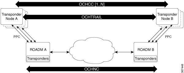
The following figure shows the relationships and optical flow between the OCHCC, OCH trail, and OCHNC circuits.

Figure 2. Optical Channel Management

Administrative and Service States

OCHCCs, OCH trails, and OCHNCs occupy three different optical layers. Each OCH circuit has its own administrative and service states. The OCHCCs impose additional restrictions on changes that can be made to client card port administrative state.

The OCHCC service state is the sum of the OCHCC service state and the OCH trail service state. When creating an OCHCC circuit, you can specify an initial state for both the OCHCC and the OCH trail layers, including the source and destination port states. The ANSI/ETSI administrative states for the OCHCC circuits and connections are:

  • IS/Unlocked

  • IS,AINS/Unlocked,AutomaticInService

  • OOS,DSBLD/Locked,disabled

OCHCC service states and source and destination port states can be changed independently. You can manually modify client card port states in all traffic conditions. Setting an OCHCC circuit to OOS,DSBLD/Locked,disabled state has no effect on OCHCC client card ports.

An OCH trail is created automatically when you create an OCHCC. OCH trails can be created independently between OCH-10G cards and GE_XP and 10GE_XP when they are provisioned in Layer 2 Over DWDM mode. The OCH trail ANSI/ETSI administrative states include:

  • IS/Unlocked

  • IS,AINS/Unlocked,automaticInService

  • OOS,DSBLD/Locked,disabled

You can modify OCH trail circuit states from the Edit Circuit window. Placing an OCH trail OOS,DSBLD/Locked,disabled causes the following state changes:

  • The state of the OCH trail ports changes to OOS,DSBLD/Locked,disabled.

  • The OCHNC state changes to OOS,DSBLD/Locked,disabled.

Changing the OCH trail state to IS,AINS/Unlocked,automaticInService causes the following state changes:

  • The state of the OCH trail trunk ports changes to IS/Unlocked.

  • The OCHNC state changes to IS,AINS/Unlocked,automaticInService.

The OCH trail service state is the sum of the OCHCC trunk port state and the OCHNC (if applicable) state. Changing the client card trunk ports to OOS,DSBLD/Locked,disabled when the OCH trail state IS/Unlocked will cause the OCH trail state to change to OOS,DSBLD/Locked,disabled and its status to change to Partial.

The OCHNC circuit states are not linked to the OCHCC circuit states. The administrative states for the OCHNC circuit layer are:

  • IS,AINS/Unlocked,AutomaticInService

  • OOS,DSBLD/Locked,disabled

When you create an OCHNC, you can set the target OCHNC circuit state to IS/Unlocked or OOS,DSBLD/Locked,disabled. You can create an OCHNC even if OCHNC source and destination ports are OOS,MT/Locked,maintenance. The OCHNC circuit state will remain OOS-AU,AINS/Unlocked-disabled,automaticInService until the port maintenance state is removed. During maintenance or laser shutdown, the following behavior occurs:

  • If OCHNCs or their end ports move into an AINS/AutomaticInService state because of user maintenance activity on an OCHCC circuit (for example, you change an optical transport section (OTS) port to OOS,DSBLD/Locked,disabled), Cisco Transport Controller (CTC) suppresses the loss of service (LOS) alarms on the TXP, MXP, GE_XP, 10GE_XP, or ITU-T line card trunk ports and raises a Trail Signal Fail condition. Line card trunk port alarms are not changed, however.

  • If TXP client or trunk port are set to OOS,DSBLD/Locked,disabled state (for example, a laser is turned off) and the OCH trunk and OCH filter ports are located in the same node, the OCH filter LOS alarm is demoted by a Trail Signal Fail condition.

OCHCCs are associated with the client card end ports. Therefore, the following port parameters cannot be changed when they carry an OCHCC:

  • Wavelength

  • Service (or payload type)

  • Splitter protection

  • ITU-T G.709

  • Forward error correction (FEC)

  • Mapping

Certain OCHCC parameters, such as service type, service size, and OCHNC wavelength can only be modified by deleting and recreating the OCHCC. If the OCHCC has MXP end ports, you can modify services and parameters on client ports that are not allocated to the OCHCC. Some client port parameters, such as Ethernet frame size and distance extension, are not part of an OCHCC so they can be modified if not restricted by the port state. For addition information about administrative and service states, see the Administrative and Service States document.

Creating and Deleting OCHCCs

To create an OCHCC, you must know the client port states and their parameters. If the client port state is IS/Unlocked, OCHCC creation will fail if the OTN line parameters (ITU-T G.709, FEC, signal fail bit error rate (SF BER), and signal degrade bit error rate (SD BER) on the OCHCC differ from what is provisioned on the trunk port. The port state must be changed to OOS-DSLB/Locked,disabled in order to complete the OCHCC.

If you delete an OCHCC, you can specify the administrative state to apply to the client card ports. For example, you can have the ports placed in OOS,DSBLD/Locked,disabled state after an OCHCC is deleted. If you delete an OCHCC that originates and terminates on MXP cards, the MXP trunk port states can only be changed if the trunk ports do not carry other OCHCCs.

OCHCCs and Service and Communications Channels

Although optical service channels (OSCs), generic communications channels (GCCs), and data communications channels (DCCs) are not managed by OCHCCs, the following restrictions must be considered when creating or deleting OCHCCs on ports with service or communication channels:

  • Creating an OCHCC when the port has a service or a communications channel is present—OCHCC creation will fail if the OCHCC parameters are incompatible with the GCC/DCC/GCC. For example, you cannot disable ITU-T G.709 on the OCHCC if a GCC carried by the port requires the parameter to be enabled.

  • Creating a service or communications channel on ports with OCHCCs—OCHCC creation will fail if the GCC/DCC/GCC parameters are incompatible with the OCHCC.

  • Deleting an OCHCC on ports with service or communications channels—If an OSC/GCC/DCC is present on a TXP, MXP, GE_XP, 20GE_XP, or ITU-T line card client or trunk port, you cannot set these ports to the OOS,DSBLD/Locked,disabled state after the OCHCC circuit is deleted.

Optical Cross Connection Label

Optical Cross Connection (OXC) label is an alphanumeric label, 12 characters long, and used as an identifier on the flex nodes.

The OXC label is used for all entities, labels, and general information related to an allocated spectrum slice. The OXC label is related to an OXC only on a specific node.

There are two ways to create OXC:
  • An end-to-end circuit provisioning through WSON (TL1, UNI, or CTC), through the network, built by a sequence of OXC on neighbor nodes. All OXCs of the circuit have the same label.
  • A single OXC created through TL1 legacy commands, where each node gets an OXC creation request, and the end-to-end consistency of central frequency, and width must be maintained by the client.

The management of optical path with the same frequency and the same width on the neighbor nodes is supported. Two OXCs with the same label in the same port is not supported. The labels that are not uniquely identified results in a label collision. The OXC label is not applicable on legacy nodes. In legacy nodes, the OXC identifier is the central wavelength in nanometers

Virtual Patchcords

The TXP, MXP, TXPP, MXPP, GE_XP, 10GE_XP, and ADM-10G client ports and DWDM filter ports can be located in different nodes or in the same single-shelf or multishelf node. ITU-T line card trunk ports and the corresponding DWDM filter ports are usually located in different nodes.

OCHCC provisioning requires a virtual patchcord between the client card trunk ports and the DWDM filter ports. Depending on the physical layout, this can be an internal patchcord or a provisionable (external) patchcord (PPC). Both patchcord types are bidirectional. However, each direction is managed as a separate patchcord.

Internal patchcords provide virtual links between the two sides of a DWDM shelf, either in single-shelf or multishelf mode. They are viewed and managed in the Provisioning > WDM-ANS > Internal Patchcords tab.

When the NE update file is imported in CTC, the Provisioning > WDM-ANS > Internal Patchcord tab is populated with the internal patchcords. When you create an internal patchcord manually, the Internal Patchcord Creation wizard prompts you to choose one of the following internal patchcord types:

  • Trunk to Trunk (L2)—Creates an internal patchcord between two trunk ports (in NNI mode) of a GE_XP, 10GE_XP, GE_XPE, or 10GE_XPE card provisioned in the L2-over-DWDM mode.

  • OCH-Trunk to OCH-Filter—Creates an internal patchcord between the trunk port of a TXP, MXP, GE_XP, 10GE_XP, or ITU-T line card, and an OCH filter card (wavelength selective switch, multiplexer, or demultiplexer).

  • OCH-Filter to OCH-Filter—Creates an internal patchcord between a MUX input port and a DMX output port.

  • OTS to OTS—Creates an internal patchcord between two OTS ports.

  • Optical Path—Creates an internal patchcord between two optical cards, or between an optical card and a passive card.


    Note


    If a Side-to-Side PPC is created between nodes, it will no longer function if the node Security Mode mode is enabled (see the “DLP-G264 Enable Node Security Mode” procedure). When the Secure mode is enabled, it is no longer possible for the DCN extension feature to use the LAN interface to extend the internal network (due to the network isolation in this configuration mode). The result is that the topology discovery on the Side-to-Side PPC no longer operates.


The following table shows the internal patchcord Trunk (L2), OCH trunk, OCH filter, and OTS/OCH ports.

Table 3. Internal Patchcord Ports

Card

Trunk (L2) Port

OCH Trunk Ports

OCH Filter Ports

OTS/OCH Ports

GE_XP

10GE_XP

GE_XPE

10GE_XPE

Trunk port in NNI mode

Any trunk port

TXPs

MXPs

ADM-10G

ITU-T line cards

Any trunk port

OPT-BST

OPT-BST-E

OPT-BST-L

COM-TX

COM-RX

OSC-TX

OSC-RX

OPT-AMP-17-C

OPT-AMP-L

COM-TX

COM-RX

Note


The following OTS/OCH ports are used when provisioned in OPT-PRE mode

OSC-TX

OSC-RX

DC-TX

DC-RX

OPT-PRE

COM-TX

COM-RX

DC-TX

DC-RX

OSCM

OSC-CSM

COM-TX

COM-RX

OSC-TX

OSC-RX

32MUX

32MUX-O

40-MUX-C

Any CHAN RX port

COM-TX

32DMX

32DMX-L

32DMX-O

40-DMX-C

40-DMX-CE

Any CHAN TX port

COM-RX

32WSS

32WSS-L

40-WSS-C

40-WSS-CE

Any ADD port

COM-TX

COM-RX

EXP-TX

EXP-RX

DROP-TX

40-WXC-C

ADD-RX

DROP-TX

COM TX

COM RX

MMU

EXP A TX

EXP A RX

PPCs are created and managed from the network view Provisioning > Provisionable Patchcord (PPC) tab, or from the node view (single-shelf mode) or multiself view (multishelf mode) Provisioning > Comm Channel > PPC tab.

Figure 3. Network View Provisionable Patchcords Tab

PPCs are required when the TXP, MXP, GE_XP, 10GE_XP, ADM-10G, or ITU-T line card is installed in a different node than the OCH filter ports. They can also be used to create OTS-to-OTS links between shelves that do not have OSC connectivity. PPCs are routable and can be used to discover network topologies using Open Shortest Path First (OSPF). GCCs and DCCs are not required for PPC creation. When you create a PPC, the PPC Creation wizard asks you to choose one of the following PPC types:

  • Client/Trunk to Client/Trunk (L2)—Creates a PPC between two client or trunk ports (in NNI mode) on GE_XP, 10GE_XP, GE_XPE, or 10GE_XPE cards provisioned in the L2-over-DWDM mode.

  • Client/Trunk to Client/Trunk—Creates a PPC between two client or trunk ports on TXP, MXP, GE_XP, 10GE_XP, ADM_10G, or ITU-T line cards.

  • Side to Side (OTS)—Creates a PPC between two OTS ports that belong to a Side. This option establishes data communications network (DCN) connectivity between nodes that do not have OSCM or OSC-CSM cards installed and therefore do not have OSC connectivity. CTC selects the OTS ports after you choose the origination and termination sides.

  • OCH Trunk to OCH Filter—Creates a PPC between an OCH trunk port on a TXP, MXP, GE_XP, 10GE_XP, ADM-10G, or ITU-T line card and an OCH filter port on a multiplexer, demultiplexer, or wavelength selective switch card.

The following table shows the PPC Client/Trunk (L2), Client/Trunk, OTS, and OCH Filter ports.

Table 4. Provisionable Patchcord Ports

Card

Client/Trunk (L2) Port

Client/Trunk Port

OTS Port

OCH Filter Port

GE_XP

10GE_XP

GE_XPE

10GE_XPE

Client or trunk port in NNI mode

Any trunk port

TXPs

MXPs

ADM-10G

ITU-T line cards

Any trunk port

OPT-BST

OPT-BST-E

OPT-BST-L

COM RX (Lines nodes only)

LINE RX

LINE TX

OPT-AMP-17-C

OPT-AMP-L

COM RX (When card mode is OPT-PRE)

The following OTS ports are used when card mode is OPT-LINE:

COM TX

LINE RX

LINE TX

OPT-PRE

The following OTS ports are used when line nodes with two OPT-PRE cards and no BST cards are installed:

COM RX

COM TX

OSC-CSM

COM RX (Lines nodes only)

LINE RX

LINE TX

32MUX

32MUX-O

40-MUX-C

Any CHAN RX port

32DMX

32DMX-L

32DMX-O

40-DMX-C

40-DMX-CE

Any CHAN TX port

32WSS

32WSS-L

40-WSS-C

40-WSS-CE

Any ADD port

40-WXC-C

COM RX

COM TX

80-WXC-C

EAD i, i=1 to 8

AD

COM

COM-RX

DROP-TX

EXP-TX

16-WXC-FS

EXP TX i, i=1 to 16

EXP RX i, i=1 to 16

COM RX

COM TX

UPG TX

UPG RX

40-SMR1-C

40-SMR2-C

LINE RX

LINE TX

17 SMR9 FS, 24 SMR9 FS, 34 SMR9 FS, SMR20 FS

LINE RX

LINE TX

OSC RX

OSC TX

EXP TX

EXP RX

MMU

EXP A RX

EXP A TX

For related procedure, see NTP-G184 Create a Provisionable Patchcord, page 17-76

PPC Provisioning Rules

For Client/Trunk to Client/Trunk (L2) PPCs, the following provisioning rules and conditions apply:

  • The card must be provisioned in the L2-over-DWDM mode.

  • The client or trunk ports must be in the NNI mode.

  • PPCs can be created only between NNI ports of the same size (1GE-1GE or 10GE-10GE).

  • A wavelength check is not performed during L2 trunk-to-trunk patchcord provisioning. The source and destination wavelengths of a L2 trunk-to-trunk PPC can be different.

For Client/Trunk to Client/Trunk PPCs, the following provisioning rules and conditions apply:

  • Patchcords can be created on preprovisioned or physically installed cards.

  • Trunk-to-trunk connections require the same wavelength if the port is equipped. A wavelength check is automatically performed during patchcord provisioning.

  • For connections involving one or more preprovisioned ports, no compatibility check is performed.

For OCH Trunk to OCH Filter PPCs, the following provisioning rules and conditions apply:

  • GCC and DCC links are not required to create a PPC.

  • PPCs can be created for preprovisioned or physically installed cards.

  • OCH trunk and OCH filter ports must be on the same wavelength. CTC checks the ports for wavelength compatibility automatically during PPC provisioning.

  • For OC-48/STM-16 and OC-192/STM-64 ITU-T line cards, the wavelength compatibility check is performed only when the cards are installed. The check is not performed for preprovisioned cards.

  • For all other preprovisioned cards, a wavelength compatibility check is not performed if card is set to first tunable wavelength. The wavelength is automatically provisioned on the port, according to the add/drop port that you chose when you created the PPC.

For related procedures, see NTP-G200 Creating, Deleting, and Managing STS or VC Circuits for the ADM-10G Card

End-to-End SVLAN Circuit

An end-to-end SVLAN circuit can be created between GE_XP, 10GE_XP, GE_XPE, or 10GE_XPE cards through a wizard in CTC. SVLAN circuits created this way are only a snapshot of the SVLAN settings (NNI and QinQ) of each card in the network. If an end-to-end SVLAN circuit is created via CTC and the SVLAN settings of the cards are changed manually, CTC does not update the SVLAN circuit created with the new settings. To update the SVLAN circuit in CTC, the circuit must be refreshed.

However, any changes made to subtended OCH trail circuits are reflected in the SVLAN circuit in CTC. If an OCH trail becomes incomplete and the current SVLAN circuit snapshot has some SVLAN circuits that are using it, they remain incomplete. If the snapshot contains incomplete SVLAN circuits and an OCH trail circuit becomes available, the incomplete SVLAN circuit snapshot in CTC appears to be complete.

When the destination port of the SVLAN circuit facing the router is configured as a NNI client port, the outgoing ethernet packets do not drop the SVLAN tag when they exit the MSTP network allowing the router to determine the origin of the ethernet packet.

SVLAN circuits are stateless circuits; an administrative or service state need not be set.


Note


During SVLAN provisioning, if a SVLAN circuit span using UNI ports in transparent mode is over subscribed, a warning message is displayed. However, the circuit is created. This is supported on channel groups on GE_XP, 10GE_XP, GE_XPE, or 10GE_XPE cards.


For related procedures, see:

End-to-End SVLAN Provisioning Rules

The following provisioning rules and conditions apply to end-to-end SVLAN circuits:

  • GE_XP, 10GE_XP, GE_XPE, and 10GE_XPE cards must be provisioned in L2-over-DWDM mode.

  • SVLAN database must be loaded with the SVLAN.

  • SVLAN circuits are routed through OCH trail circuits or PPC; Client/Trunk to Client/Trunk (L2). Therefore, before creating an SVLAN circuit, make sure that the subtended OCH trail circuits between GE_XP, 10GE_XP, GE_XPE, and 10GE_XPE cards or PPC links are created.

  • For protected SVLAN circuits, create a ring (through OCH trail circuits), define a primary node, and enable the protection role.

For information on how to create end-to-end SVLAN circuit, see the NTP-G203 Creating End-to-End SVLAN Circuits procedure.

NTP-G151 Creating, Deleting, and Managing Optical Channel Client Connections

Purpose

This procedure creates, deletes, and manages OCHCC circuits. The OCHCC circuits can be created using the Circuit Creation wizard or the Circuit Creation view. OCHCCs create an end-to-end optical management path between TXP, MXP, GE_XP, 10GE_XP, GE_XPE, and 10GE_XPE (when provisioned as TXPs or MXPs), OTU2_XP, 100G-LC-C, 10x10G-LC, CFP-LC, 100G-CK-C, 100GS-CK-LC, 200G-CK-LC, AR_MXP, AR_XP, or AR_XPE client ports, or between ITU-T trunk ports. ITU-T line cards include: OC48 ELR/STM64 EH, OC192 SR1/STM64 IO, MRC-12, MRC-2.5-12, and MRC-2.5G-4. An OCHCC circuit can also be created between the MSTP TXP client interface and the router PLIM interface (10 G or 100 G ethernet client interface). The OCHCC circuit is transported by an OCH trail circuit that is associated to one or more OCHNC circuits (for example, an OCHCC circuit passing through a regen node).

Tools/Equipment

None

Prerequisite Procedures

Required/As Needed

As needed

Onsite/Remote

Onsite or remote

Security Level

Provisioning or higher


Note


This procedure is not applicable to the ADM-10G card or GE_XP, 10GE_XP, GE_XPE, and 10GE_XPE cards that are provisioned in L2-over-DWDM mode.


Procedure


Step 1

As needed, identify the OCHCC to be provisioned using the DLP-G350 Use the Cisco Transport Planner Traffic Matrix Report.

Step 2

If you want to assign a name to the OCHCC source and destination ports before you create the circuit, complete the DLP-G104 Assigning a Name to a Port. If not, continue with Step 3.

Tip Naming the client ports help in identifying them correctly later.

Step 3

If the client TXP, MXP, or ITU-T line cards are installed in a multishelf node, continue with Step 4. If not, complete the following substeps:

  1. Use the information obtained from the Cisco Transport Planner traffic matrix report in Step 1 to complete the DLP-G344 Verifying Provisionable and Internal Patchcords. If provisionable patchcords (PPCs) exist between the nodes containing the TXP/MXP/ITU-T line cards and the DWDM nodes at each end of the OCHCC, continue with Step 4. If not, continue with Step b.

  2. Complete the NTP-G184 Creating a Provisionable Patchcord to create the PPCs between the OCHCC source and destination nodes.

    Note


    For the AR_XPE card, you can specify the ODU0 and ODU1 trunk side bandwidth when a 1GE or 1GFC payload is configured on the card.

Step 4

If the client TXP/MXP/ITU-T line cards are installed in a multishelf node, use the information obtained from the Cisco Transport Planner traffic matrix report in Step 1 to create internal patchcords between the 32DMX, 32DMX-O, or 32DMX-L ports and the TXP/MXP trunk ports using the "NTP-G242 Create an Internal Patchcord Manually" procedure. Create the internal patchcords on both the source and destination nodes of each OCHCC path. If the TXP/MXP/ITU-T line cards are not installed in a multishelf node, continue with Step 5.

Step 5

Complete the DLP-G345 Verifying OCHCC Client Ports to verify the port rate and service state.

Step 6

To provision the OCHCC circuit, use either of the following procedures as needed:

Step 7

Complete the DLP-G706 Performing Optical Validation of GMPLS Circuits, as needed.

Step 8

Complete the DLP-G707 Upgrading a Non-GMPLS Circuit to a GMPLS Circuit, as needed.

Step 9

Complete the DLP-G777 Upgrading a GMPLS Circuit from Legacy Signaling to LOGO Signaling, as needed.

Step 10

Complete the DLP-G424 Editing an OCHCC Circuit Name, as needed.

Step 11

Complete the DLP-G394 Changing an OCHCC Administrative State, as needed.

Step 12

Complete the DLP-G347 Deleting Optical Channel Client Connections, as needed.

Stop. You have completed this procedure.


DLP-G104 Assigning a Name to a Port

Purpose

This task assigns a name to a port on any card.

Tools/Equipment

None

Prerequisite Procedures

DLP-G46 Log into CTC

Required/As Needed

As needed

Onsite/Remote

Onsite or remote

Security Level

Provisioning or higher

Procedure


Step 1

In node view, double-click the card that has the port that you want to provision. This can be any port on a traffic-carrying card. The card view opens.

Step 2

Click the Provisioning tab.

Step 3

Double-click the Port Name table cell for the port number where you are assigning a name. The cell activates and a blinking cursor indicates where you should enter the port name.

Step 4

Enter the port name.

The port name can be up to 80 alphanumeric/special characters. The field is blank by default.

Step 5

Click Apply.

Step 6

Return to your originating procedure (NTP).


DLP-G345 Verifying OCHCC Client Ports

Purpose

This task verifies the rate and service state of the OCHCC client ports.

Tools/Equipment

None

Prerequisite Procedures

DLP-G46 Log into CTC

Required/As Needed

As needed

Onsite/Remote

Onsite or remote

Security Level

Provisioning or higher

Procedure


Step 1

In node view, double-click the TXP, MXP, OTU2_XP, AR_MXP, AR_XP, AR_XPE, or ITU-T line card where you want to verify the client ports. The card view opens.

Step 2

Click the Provisioning > Maintenance tabs.

Step 3

Click the Provisioning > Pluggable Port Modules tabs.

Step 4

Verify that a pluggable port module has been created and that the port rate under the Pluggable Port area is provisioned. If so, continue with Step 5. If not, complete the DLP-G726 Preprovisioning a Multirate PPM and "DLP-G278 Provision the Optical Line Rate” tasks.

Step 5

Repeat Steps 1 through 4 for each TXP, MXP, OTU2_XP, AR_MXP, AR_XP, AR_XPE, or ITU-T line card containing OCHCC ports that you want to verify.

Step 6

Return to your originating procedure (NTP).


DLP-G346 Provisioning Optical Channel Client Connections

Purpose

This task creates an OCHCC between two TXP, MXP, GE_XP and GE_XPE (when configured in TXP or MXP mode), 10GE_XP and 10GE_XPE (when configured in TXP or MXP mode), OTU2_XP, AR_MXP, AR_XP, or AR_XPE client ports, or two ITU-T-compliant line card trunk ports.

Tools/Equipment

Cisco Transport Planner Traffic Matrix Report

Prerequisite Procedures

DLP-G46 Log into CTC

DLP-G345 Verifying OCHCC Client Ports

Required/As Needed

As needed

Onsite/Remote

Onsite or remote

Security Level

Provisioning or higher


Note


OCHCCs can be created on preprovisioned client cards or physically installed client cards.


Note


Creating an OCHCC circuit automatically creates an OCH trail circuit between the OCHCC source and destination client card trunk ports. The OCH trail circuit is created for the first OCHCC between two MXP cards. The OCH trail circuit is used by succeeding OCHCCs created between the MXP cards. When the OCH trail is created, it is assigned a system-generated name in the format circuit-type_NE-name::unique sequence number. To edit the OCH trail circuit name, complete the DLP-G424 Editing an OCHCC Circuit Name.


Note


If trunk ports are connected by a peer-to-peer provisionable patchcord (PPC), an OCH trail is not created.


Note


The OCH Wlen (wavelength) parameter on the Circuits page can be used to determine the OCHCC and OCH trail associations.


Note


If you want the OCHCC circuit to provision the client card trunk port’s ITU-T G.709, FEC, SD and SF threshold settings and Mapping parameters, you must place the client card trunk ports out of service. If any of the trunk ports, including OTU2-XP regen ports, are in-service state, a warning message “Trunk settings are not applied on any of the trunk ports” is displayed with details of the trunk ports that are in in-service state.


Note


In a node using OTU2_XP cards configured in the regen mode, a single OCHCC circuit can be created that passes through the OTU2_XP card. Internal patch cords must be created from the OTU2_XP regen ports to the respective add/drop cards. OCHCC circuit creation through OTU2_XP cards in regen mode is not supported if different wavelengths are used on the two OTU2_XP regen ports.


Note


The OCHCC circuit creation is not supported between different payloads in the 40G-MXP-C, 40E-MXP-C, and 40ME-MXP-C cards.


Note


The 40G-MXP-C card configured in the unidirectional regen mode does not support OCHCC circuit creation. Two bidirectional OCHNC circuits can be created, one on either side of the regenerator group for managing the circuit.


Note


In AR_MXP, AR_XP, and AR_XPE cards, you cannot create the circuits using FICON payload option in Circuit Creation wizard. Create circuits using FC payload to bring up FICON traffic.


Note


If loopback is configured on the VTXP port, CTC does not create the OCHCC and OCH Trail circuits and displays a warning message.

Procedure


Step 1

From the View menu, choose Go to Network View.

Step 2

Click the Circuits tab, then click Create.

Step 3

In the Circuit Creation dialog box, choose OCHCC from the Circuit Type list.

Step 4

Click Next.

Step 5

In the Circuit area of the Circuit Attributes page, provision the OCHCC circuit attributes:

  • Name—Assign a name to the OCHCC. The name is limited to 80 characters, which can be a combination of alphanumeric (a-z, A-Z, 0-9) and special characters (+, #,%, and so on, including spaces). Circuit names should be 44 characters or less if you want the ability to create monitor circuits. If you leave the field blank, Cisco Transport Controller (CTC) assigns a default name to the circuit. When a circuit includes a network element with release prior to 9.60, the circuit name is limited to 48 characters.

  • Type—(Display only) OCHCC.

  • Size—Defines the circuit payload type and rate. Two fields are provided. The first specifies the payload type. Choose a payload type, then choose the rate in the next field. The following table provides the OCHCC payload types and rates.

    Note


    The payload type and rate must match the PPM provisioning on the client cards at the source and destination nodes.

Table 5. OCHCC Client Rates

Payload Type

Rates

SONET/SDH

OC-192 (ANSI)/STM-64 (ETSI)—9.92 Gbps

OC-48 (ANSI)/STM-12 (ETSI)—2.48 Gbps

OC-12 (ANSI)/STM-4 (ETSI)—622 Mbps

OC-3 (ANSI)/STM-1 (ETSI)—155 Mbps

Ethernet

10GE—One Gigabit Ethernet 11.25 Gbps

1GE—One Gigabit Ethernet 1.125 Gbps

FC/FICON

10GFC—Fibre Channel 10 Gbps

4GFC—Fibre Channel 4 Gbps

2GFC—Fibre Channel 2.125 Gbps

1GFC—Fibre Channel 1.06 Gbps

4GFICON—FICON 4 Gbps

2GFICON—FICON 2.125 Gbps

1GFICON—FICON 1.06 Gbps

Data Storage

ESCON—Enterprise System Connection 200 Mbps (IBM signal)

ISC Peer—Inter System Coupling Link 3 (ISC3)

ISC3 Peer 1G—InterSystem Coupling Link 3 (ISC3) 1 Gbps

ISC3 Peer 2G—InterSystem Coupling Link 3 (ISC3) 2 Gbps

ISC COMPAT—InterSystem Coupling Link 1 (ISC1)

ISC1—Inter system connect Link 1 (ISC1)

Video

HDTV—High Definition Television

SDI/DI—Serial Digital Interface and Digital Video signal type 1

DV6000—Proprietary signal from video vendor

DVB-ASI—Proprietary signal from video vendor

Other

Pass Through—Creates a pass-through OCHCC

  • OCHNC Wavelength—Provides three fields to define the wavelength that the OCHCC will use to travel across the OCH network. Choose a wavelength from the first field. In the second field, you can change the wavelength band by choosing either C Band or L Band. In the third field, you can indicate whether odd or even C-band or L-band wavelengths appear. See the following tables for C-band and L-band wavelengths.

    Note


    The OCHNC wavelength must match the trunk wavelength provisioned on the source and destination TXP or MXP cards. If the wavelengths do not match, the card will not appear as a source or destination.

Table 6. OCH C-Band Channels

Channel No.

Channel ID

Frequency (GHz)

Wavelength (nm)

1

30.3

195.9

1530.33

2

31.1

195.8

1531.12

3

31.9

195.7

1531.90

4

33.4

195.5

1532.68

5

32.6

195.6

1533.47

6

34.2

195.4

1534.25

7

35.0

195.3

1535.04

8

35.8

195.2

1535.82

9

36.1

195.1

1536.61

10

37.4

195

1537.40

11

38.1

194.9

1538.19

12

38.9

194.8

1538.98

13

39.7

194.7

1539.77

14

40.5

194.6

1540.56

15

41.3

194.5

1541.35

16

42.1

194.4

1542.14

17

42.9

194.3

1542.94

18

43.7

194.2

1543.73

19

44.5

194.1

1544.53

20

44.3

194

1545.32

21

46.1

193.9

1546.12

22

46.9

193.8

1546.92

23

47.7

193.7

1547.72

24

48.5

193.6

1548.51

25

49.3

193.5

1549.32

26

50.1

193.4

1550.12

27

50.9

193.3

1550.92

28

51.7

193.2

1551.72

29

52.5

193.1

1552.52

30

53.3

193

1553.33

31

54.1

192.9

1554.13

32

54.9

192.8

1544.94

33

55.7

192.7

1555.75

34

56.5

192.6

1556.55

35

57.3

192.5

1557.36

36

58.1

192.4

1558.17

37

58.9

192.3

1558.98

38

59.7

192.2

1559.79

39

60.6

192.1

1560.61

40

61.3

192

1561.42

Note


The wavelengths 1533.47, 1537.40, 1541.35, 1545.32, 1549.32, 1553.33 1557.36, 1561.42 from the above table require 40-channel MUX or WSS cards, and 40-channel DMX cards.

Table 7. OCH L-Band Channels

Channel Number

Frequency (THz)

Wavelength (nm)

Channel Number

Frequency (THz)

Wavelength (nm)

1

190.85

1570.83

41

188.85

1587.46

2

190.8

1571.24

42

188.8

1587.88

3

190.75

1571.65

43

188.75

1588.30

4

190.7

1572.06

44

188.7

1588.73

5

190.65

1572.48

45

188.65

1589.15

6

190.6

1572.89

46

188.6

1589.57

7

190.55

1573.30

47

188.55

1589.99

8

190.5

1573.71

48

188.5

1590.41

9

190.45

1574.13

49

188.45

1590.83

10

190.4

1574.54

50

188.4

1591.26

11

190.35

1574.95

51

188.35

1591.68

12

190.3

1575.37

52

188.3

1592.10

13

190.25

1575.78

53

188.25

1592.52

14

190.2

1576.20

54

188.2

1592.95

15

190.15

1576.61

55

188.15

1593.37

16

190.1

1577.03

56

188.1

1593.79

17

190.05

1577.44

57

188.05

1594.22

18

190

1577.86

58

188

1594.64

19

189.95

1578.27

59

187.95

1595.06

20

189.9

1578.69

60

187.9

1595.49

21

189.85

1579.10

61

187.85

1595.91

22

189.8

1579.52

62

187.8

1596.34

23

189.75

1579.93

63

187.75

1596.76

24

189.7

1580.35

64

187.7

1597.19

25

189.65

1580.77

65

187.65

1597.62

26

189.6

1581.18

66

187.6

1598.04

27

189.55

1581.60

67

187.55

1598.47

28

189.5

1582.02

68

187.5

1598.89

29

189.45

1582.44

69

187.45

1599.32

30

189.4

1582.85

70

187.4

1599.75

31

189.35

1583.27

71

187.35

1600.17

32

189.3

1583.69

72

187.3

1600.60

33

189.25

1584.11

73

187.25

1601.03

34

189.2

1584.53

74

187.2

1601.46

35

189.15

1584.95

75

187.15

1601.88

36

189.1

1585.36

76

187.1

1602.31

37

189.05

1585.78

77

187.05

1602.74

38

189

1586.20

78

187

1603.17

39

188.95

1586.62

79

186.95

1603.60

40

188.9

1587.04

80

186.9

1604.03

  • Bidirectional—(Display only) OCHCCs are bidirectional. This field cannot be changed.

  • Protection—Check to create a splitter-protected OCHCC (only MXPP/TXPP cards will be selectable as circuit endpoints) or a protected OCHCC when TXP is connected to a PSM card.

    Note


    When splitter protection is configured for a non-WSON circuit using different wavelengths, the work and protect paths may select the same route as the shortest route unless constraints are provisioned for diverse paths. To overcome this issue, configure the circuit with constraints as described in Step 14 or create a WSON circuit using DLP-G705 Provisioning GMPLS Optical Channel Client Connections.

Step 6

In the State area of the Circuit Attributes page, provision the OCHCC state attributes:

  • State—Provisions the OCHCC circuit state. The state can be IS (ANSI)/Unlocked (ETSI) or OOS,DSBLD (ANSI)/Locked,Disabled (ETSI)

  • Apply to OCHCC ports—If checked, applies the state chosen in the Apply to OCHCC ports drop-down list to the OCHCC client ports. For TXP, MXP, TXPP, or MXPP cards, the administrative state will apply to the client and all trunk ports. For ITU-T-compliant line cards, the administrative state will apply to the trunk port only. The states that you can apply include: IS (ANSI)/Unlocked (ETSI), OOS,DSBLD (ANSI)/Locked,Disabled (ETSI), and IS,AINS (ANSI)/Unlocked,AutomaticInService (ETSI).

Step 7

Click Next.

Step 8

In the Source area, choose the source node from the Node drop-down list, then choose the source shelf (multishelf nodes only) from the Shelf drop-down list, the source slot from the Slot drop-down list, and, if needed, the source port from the Port drop-down list.

If no nodes appear in the Node drop-down list, complete the following steps:

  1. Click Back and review your circuit attribute settings. Verify that they are set to the client attributes provisioned on the client cards. If necessary, click Cancel and complete the DLP-G345 Verifying OCHCC Client Ports to verify the client settings.

  2. If the source and/or destination nodes are not configured for multishelf, complete the DLP-G344 Verifying Provisionable and Internal Patchcords to verify that the patchcords were created accurately.

    If these steps do not solve the problem, refer to your next level of support.

Step 9

Click Next.

Step 10

In the Destination area, choose the destination node from the Node drop-down list, then choose the destination shelf (multishelf nodes only) from the Shelf drop-down list, the destination slot from the Slot drop-down list, and, if needed, the destination port from the Port drop-down list.

If no nodes appear in the Node drop-down list, complete the following steps:

  1. Click Back and review your circuit attribute settings. Verify that they are set to the client attributes provisioned on the client cards. If necessary, click Cancel and complete the DLP-G345 Verifying OCHCC Client Ports to verify the client settings.

  2. If the source and/or destination nodes are not configured for multishelf, complete the DLP-G344 Verifying Provisionable and Internal Patchcords to verify that the patchcords were created accurately.

    If these steps do not solve the problem, refer to your next level of support.

Step 11

Click Next. If the OCHCC is between ITU-T cards, continue with Step 12. If not, skip to Step 14.

Step 12

Complete the DLP-G347 Deleting Optical Channel Client Connections.

Step 13

Click Next.

Step 14

Complete the DLP-G438 Setting OCH Routing Preferences. Skip this step and continue with Step 16 if no constraints are needed. If the trunk ports are already connected by an existing OCH Trail (MXP case) or by a direct PPC link, the OCH Circuit Routing Preferences page appears in read-only mode; all buttons are disabled. Continue with Step 16.

Step 15

If the circuit is being created for AR_MXP, AR_XP, or AR_XPE card with MXP_MR (low or high rate) or MXPP_MR (low or high rate) operating mode, select the ODU1 and the respective timeslot within the selected ODU1. The following table describes the bandwidth utilization for the selected payload.

Note


For the all other cards/card modes, you cannot select the ODU1 and timeslot parameters.

Table 8. Bandwidth Utilization for the Selected Payload

Payload

Number of ODU1s required

Number of ODU0s required

Number of Timeslot required/ODU1

OC3

FE

1

1

OC12

1

4

OC48

1

16

FC2

ISC3-2G

1

14

ESCON

1

2

GE

FC1

ISC3-1G

1

1

1

NA

NA

FC4G

2

NA

Step 16

Click Finish. The OCHCC and its OCH trail appear in the Circuits page. After the circuit status has been verified, the DISCOVERED status appears in the Status column.

If the OCHCC status does not change to DISCOVERED within 2 to 3 minutes, contact your next level of support.

Step 17

Return to your originating procedure (NTP).


DLP-G705 Provisioning GMPLS Optical Channel Client Connections

Purpose

This task creates an OCHCC circuit between two TXP, MXP, GE_XP and GE_XPE (when configured in TXP or MXP mode), 10GE_XP and 10GE_XPE (when configured in TXP or MXP mode), OTU2_XP client ports, ITU-T-compliant line card trunk ports, or CRS routers. It is also possible to create an OCHCC circuit between the MSTP TXP client interface and the router PLIM interface (10 G or 100 G ethernet client interface).

Tools/Equipment

Cisco Transport Planner Traffic Matrix Report

Prerequisite Procedures

Required/As Needed

As needed

Onsite/Remote

Onsite or remote

Security Level

Provisioning or higher

When the GMPLS circuit creation fails due to optical validation, a detailed error message with diagnostic logs is displayed that explains the causes of the failure. The error message provides details of the optical validation parameters (channel power, OSNR, chromatic dispersion, acceptance threshold and so on) that cause the failure.

You cannot directly create the GMPLS OCHCC circuit on the 100G-LC-C, 10x10G-LC, CFP-LC, and 100G-CK-C cards when configured in MXP-10x10G (10x10G Muxponder) card mode or with AR-XP cards. There are two ways to create the GMPLS OCHCC circuit:

  • Create the GMPLS OCH trail and then create the OCHCC circuit.

  • Create the OCHCC circuit and then upgrade the circuit to GMPLS OCHCC circuit.


    Note


    In release 10.5, you can create the GMPLS OCHCC circuit directly using WSON from the DWDM network functional on all TXP/MXP cards except on the AR-MXP and AR-XPE cards. The OCHCC circuit can be created on the AR-XP cards only in the TXP-MR, TXPP-MR, MXP-MR-S, and MXPP-MR-S operating modes.


Note


Non-DWDM OCHCC circuits with Trunk to Trunk PPC are not supported in GMPLS circuits.

Procedure


Step 1

From the View menu, choose Go to Network View and click the DWDM Functional View icon in the toolbar. The DWDM netowrk functional view opens.

Step 2

From the Change Perspective drop-down list in the toolbar, choose Circuit Creation. The Circuit creation view opens.

Step 3

In the Circuit Parameters pane, provision the OCHCC circuit attributes:

  1. Name—Assign a name to the circuit. The name is limited to 80 characters, which can be a combination of alphanumeric (a-z, A-Z, 0-9) and special characters (+, #,%, and so on, including spaces). When a circuit includes a network element with release prior to 9.60, the circuit name is limited to 48 characters.

  2. Label—Type a name for the circuit label. The label can be an alphanumeric string up to 14 characters.

  3. Type—Choose OCHCC.

  4. Protected—Check to route the circuit on a protected path. Select the protection type from the drop-down list. The available options are:

    • PSM—When a PSM card is connected to a TXP card.

    • Y-CABLE—The circuit is protected by a transponder or muxponder card in a Y-cable protection group.

    • Splitter—When a MXPP/TXPP card is used. The circuit source and destination are on MXPP_MR_2.5G and TXPP_MR_2.5G cards. These cards provides splitter (line-level) protection.

  5. UNI VTXP— This parameter creates a UNI VTXP circuit; otherwise a VTXP circuit is created without UNI. This check box appears only when VTXP is selected as an end point.

  6. IS—Check to place the trunk ports of the TXP /MXP card in service.

  7. Wavelength Configuration — Select the check box to configure the wavelength for the circuit.

  8. GMPLS/WSON Wavelength Parameters — Choose a wavelength from the first field. Select C band in the second field. In the third field, indicate whether odd or even C-band wavelengths appear.

    • The even C-band wavelength supports 48 channels ranging from 1528.77 nm (196.10 THz) to 1566.31 nm (191.40 THz).
    • The odd C-band wavelength supports 48 channels ranging from 1529.16 nm (196.05 THz) to 1566.72 nm (191.35 THz).

    Note

     
    MSTP legacy package supports 40 odd (1530.30 to 1561.42 nm) and 0 even (1530.72 to 1561.83) channels only.
  9. Validation—Set the validation mode. For more information about validation modes, see the "Validation Modes" section in "Node Reference" chapter.

  10. Acceptance threshold—Set the optical validation threshold value for the GMPLS circuit. The circuit is created if the actual optical validation result is greater than or equal to the value set in this field. For more information about the acceptance threshold value, see the "Acceptance Thresholds" section in "Node Reference" chapter.

  11. Protection Acceptance Threshold—Sets the optical validation threshold value for the protected GMPLS circuit.

Step 4

In the GMPLS/WSON Optional Configuration pane, specify the attributes:

  1. Ignore path Alarms — Check this check box to ignore the alarms on the path and create the circuit. This parameter is used to verify whether the circuit can be created on the path.

  2. Allow Regeneration — Select this check box to allow the control plane to find a regenerator deployed in the network. The regenerators are used when an optical LSP between two endpoints is not optical or lambda feasible with a single DWDM channel.

  3. Circuit Diversity — Select this option to provision a diversity path for the circuit. From the circuit pane, choose the an existing circuit that will be used as reference for the LSP diversity. The diverse path that is not taken by the new circuit is displayed in the circuit pane.

  4. Priority — Select the priority level for the circuit. The priority is used in resolving resource allocation when two or more circuits require the same resource during circuit creation or restoration concurrently. The priority levels are 0 (High) to 7 (Low).

  5. Channel Power Offset:

    • – Upstream (dBm) — Set the value of offset in dBm, negative or positive, which the COM_TX of the card uses on its PerChannelPower default value. Upstream applies to the card in the outgoing path of the circuit.
    • – Downstream (dBm) — Set the value of offset in dBm, negative or positive, which the COM_TX of the card uses on its PerChannelPower default value. Downstream applies to the card in the incoming path of the circuit.

Step 5

Configure the source and destination ports at the circuit endpoints in the map. For more information about configuring the source and destination ports, see the "Source and Destination Port Configuration” section in "Node Reference" chapter.

Note


The OCHCC circuit endpoints must be selected on the TXP/MXP cards or the router PLIM interface. An OCHCC circuit can also be created between the MSTP TXP client interface and the router PLIM interface (10 G or 100 G ethernet client interface). If other ports are selected, a warning dialog box is displayed prompting you to change the circuit type.

Step 6

Define the working or protect port parameters. For more information, see the "Working and Protect Port Parameters” section in "Node Reference" chapter. Click Apply in the Working Port Parameters pane and Protected Port Parameters pane, to apply the settings.

Step 7

Click Apply in the Circuit Parameters pane.

Step 8

Click Yes in the Create Circuits confirmation dialog box.
The OCHCC and its OCH trail appear in the Circuits tab in the Network Data pane. After the circuit status has been verified, the DISCOVERED status appears in the Status column. Depending on the size of the network, the circuit might take a few minutes to come up

Step 9

Return to your originating procedure (NTP).


DLP-G347 Deleting Optical Channel Client Connections

Purpose

This task deletes DWDM OCHCC circuits.

Tools/Equipment

None

Prerequisite Procedures

DLP-G46 Log into CTC

Required/As Needed

As needed

Onsite/Remote

Onsite or remote

Security Level

Provisioning or higher


Note


If you are deleting more than half of all the active OCHCCs, it is recommended that you delete them two at a time to allow for proper power compensation. You do not need to delete the active OCHCCs two at a time if you are deleting all them.


Procedure


Step 1

Complete the to preserve existing settings and, if you want to recreate the circuits, record the circuit information.

Step 2

Consult your network operations center (NOC) or other appropriate personnel to verify that the OCHCC can be safely deleted.

Step 3

Investigate all network alarms and resolve any problems that might be affected by the OCHCC deletion.

Step 4

Go to the network view or the DWDM network functional view and click the Circuits tab.

Step 5

Under the Type column, choose one or more OCHCCs that you want to delete, then click Delete.

Step 6

In the Delete Circuits confirmation dialog box, complete the following:

  • Change drop port admin state—This checkbox is checked by default. Choose one of the following administrative states, if you want to change the circuit source and destination port administrative state:

    • IS (ANSI) or Unlocked (ETSI)—Puts the ports in service.

    • IS,AINS (ANSI) or UnlockedAutomaticInService (ETSI)—Puts the ports in automatic in service.

    • OOS,DSBLD (ANSI) or Locked,disabled (ETSI)—Removes the ports from service and disables them. This option is set by default.

    • OOS,MT (ANSI) or Locked,maintenance (ETSI)—Removes the ports from service for maintenance.

  • Notify when completed—Checked this box if you want the CTC Alerts confirmation dialog box to notify you when the OCHCC is deleted. During this time, you cannot perform other CTC functions. If you are deleting many OCHCCs, waiting for confirmation might take a few minutes. Circuits are deleted whether or not this check box is checked.

    Note


    The CTC Alerts dialog box will not automatically open to show a deletion error unless you checked All alerts or Error alerts only in the CTC Alerts dialog box. For more information, see the DLP-G53 Configure the CTC Alerts Dialog Box for Automatic Popup. If the CTC Alerts dialog box is not set to open automatically, the red triangle inside the CTC Alerts toolbar icon indicates that a notification exists.

Step 7

Complete either of the following:

  • If you checked Notify when completed, the CTC Alerts dialog box appears. If you want to save the information, continue with Step 8. If you do not want to save the information, continue with Step 9.

  • If you did not check Notify when completed, the Circuits page appears. Continue with Step 10.

Step 8

If you want to save the information in the CTC Alerts dialog box, complete the following substeps. If you do not want to save it, continue with Step 10.

  1. Click Save.

  2. Click Browse and navigate to the directory where you want to save the file.

  3. Type the file name using a TXT file extension, and click OK.

Step 9

Click Close to close the CTC Alerts dialog box.

Step 10

Complete the if you require a backup of your changes.

Step 11

Return to your originating procedure (NTP).


DLP-G424 Editing an OCHCC Circuit Name

Purpose

This task changes the name of an OCHCC circuit.

Tools/Equipment

None

Prerequisite Procedures

DLP-G105 Provisioning Optical Channel Network Connections

DLP-G46 Log into CTC

Required/As Needed

As needed

Onsite/Remote

Onsite or remote

Security Level

Provisioning or higher

Procedure


Step 1

Go to the network view, NFV view, or GMPLS view, and click the Circuits tab.

Step 2

To rename the OCHCC circuit, do either of the following.

  • Network view—Select the OCHCC circuit in the Circuits tab and click Edit.

  • NFV view or GMPLS view—Double-click the circuit in the Circuits tab.

Step 3

In the Edit Circuit dialog box, click the General tab.

Step 4

In the Name field, enter the new OCHCC circuit name.

Step 5

Click Apply.

Step 6

Return to your originating procedure (NTP).


DLP-G394 Changing an OCHCC Administrative State

Purpose

This task changes the administrative state of an OCHCC circuit.

Tools/Equipment

None

Prerequisite Procedures

DLP-G346 Provisioning Optical Channel Client Connections

DLP-G46 Log into CTC

Required/As Needed

As needed

Onsite/Remote

Onsite or remote

Security Level

Provisioning or higher

Procedure


Step 1

Go to the network view, Circuit Maintenance view, or Circuit Creation view, and click the Circuits tab.

Step 2

To change the administrative state of the OCHCC circuit, do either of the following.

  • Network view—Select the OCHCC circuit in the Circuits tab and click Edit.

  • Circuit Maintenance view or Circuit Creation view—Double-click the circuit in the Circuits tab.

Step 3

In the Edit Circuit dialog box, click the State tab.

Step 4

Click the cell in the Admin State column for the card you want to change, and choose an administrative state from the drop-down list:

  • IS (ANSI) or Unlocked (ETSI)

  • OOS (ANSI) or Locked (ETSI)

Step 5

Click Apply.

Step 6

If you are changing the OCHCC state to OOS/Locked, click OK in the confirmation dialog box. (No confirmation dialog box appears when placing OCHCCs in service.)

Note


For information about the OCH circuit state transitions, see the Administrative and Service States document.

Step 7

Return to your originating procedure (NTP).


DLP-G437 Setting OCH Circuit Attributes

Purpose

This task provisions OCH trunk attributes.

Tools/Equipment

None

Prerequisite Procedures

DLP-G46 Log into CTC

The OCH Circuit Attributes page must be open.

Required/As Needed

As needed

Onsite/Remote

Onsite or remote

Security Level

Provisioning or higher

Procedure


Step 1

In the OCH Circuit Attributes Preferences page, change the trunk settings as necessary. The settings provisioned here can only be provisioned on the ports when the ports are out of service. If the ports are in service, these parameters must be the same as the source and destination card ports. If not, the trunk settings are not editable and are retained as they are on both the trunk ports. An information pop up window is shown after the circuit creation indicating that the trunk settings are not applied on any of the trunk ports. You can view the current trunk settings (display only) in the Current Values area.

  • To change any of the trunk settings, complete the following in the Provisioning Values area:

    • ITU-T G.709 OTN—Choose Enable or Disable to set or disable the IEEE G.709 monitoring on the optical transport network. If the OCHCC source or destination is an TXP_MR_10EX_C, 40E-TXP-C, 40ME-TXP-C, MXP_2.5G_10E, MXP_2.5G_10E_C, MXP_2.5G_10E_L, MXP_2.5G_10EX_C, MXP_MR_10DMEX_C, 40G-MXP-C, 40E-MXP-C, or 40ME-MXP-C card, the ITU-T G.709 OTN parameter must always be checked. If ITU-T G.709 OTN is checked, the MXP_MR_2.5G and MXPP_MR_2.5G cards will not appear as OCHCC source and destination options.

    • FEC—Choose the type of FEC: Disabled, Standard, or Enhanced. The options that appear depend on the card type. If the OCHCC source or destination is an TXP_MR_10EX_C, MXP_2.5G_10EX_C, MXP_MR_10DMEX_C, 40G-MXP-C, 40E-MXP-C, 40ME-MXP-C, 40E-TXP-C, or 40ME-TXP-C card, the ITU-T G.709 OTN parameter must always be checked.

    • SD BER—Choose the signal degrade bit error rate. The range of SD BER values supported for Cisco 7600 router is from 5 to 9.

    • (Cisco 7600 series routers only) OPU—Choose the ITU-T G.709 OPU standard. OPU-1E and OPU-2E standards are supported on the Cisco 7600 series routers.

    • SF BER—Choose the signal fail bit error rate.

    • Mapping—Sets the mapping for the TXP_MR_10E, TXP_MR_10E_C, TXP_MR_10E_L, TXP_MR_10EX_C, MXP_MR_10DME_C, MXP_MR_DME_L, and MXP_MR_10DMEX_C cards: Not Used, ODU Multiplex (client SONET/SDH payload), Asynchronous, or Synchronous. The choices available depend on the card. If you set mapping to Synchronous, the client signal is mapped into the OTU2 signal without justification of the payload because the client signal timing (the timing source) is the same as the trunk output timing. If you set mapping to Asynchronous, the trunk timing is disconnected from the client timing (because the network element [NE] is the timing source), so justification is needed to map the client signal (OC192/STM64) to OTU2 trunk output.

      Note


      When you create a 4xOC-48 OCHCC circuit, you need to select the G.709 and Synchronous options. A 4xOC-48 OCHCC circuit is supported by G.709 and synchronous mode. This is necessary to provision a 4xOC-48 OCHCC circuit.

      Note


      If the OCHCC source or destination is an MXP_2.5G_10E, MXP_2.5G_10E_C, MXP_2.5G_10E_L, or MXP_2.5G_10EX_C card, the Mapping parameter must always be set to Synch.

    Set the proactive protection attributes. Proactive Protection Regen is supported on OTU2XP ports alone in Standard Regen and Enhanced FEC mode

    Note


    Proactive protection regen is supported only on CRS-based OCH trails.

  • Proactive Protection—Choose Enable or Disable.

  • Trigger Threshold—Choose the minimum BER threshold to trigger proactive protection by sending forward defect indication (FDI).

  • Trigger Window—The trigger window value must be in multiples of 10 ms for trigger thresholds between 1E-3 and 6E-6 or 100 ms for trigger threshold between 5E-6 to 1E-7. Enter the duration to monitor the BER before triggering the proactive protection. The trigger window must be less than or equal to 10000 ms.

  • Revert Threshold—Choose a BER value, to indicate the threshold at which the FDI is cleared to allow traffic.

  • Revert Window—Enter the duration to monitor the BER for which it should be less than the revert threshold value before removing the FDI sent to the router.
The revert window must be less than or equal to 10000ms. The revert window value must be at least 2000ms and in multiples of 10ms for a Revert Threshold of 1E-4 to 6E-7, or 100ms for a Revert Threshold of 5E-7 to 5E-8.

  • Set the protection in the Protection area, as needed. The fields in the protection area are disabled if the OCHCC is not protected and for OCH Trails. Set the following attributes:

    • Revertive—If checked, traffic reverts to the working card after failure conditions remain corrected for the amount of time entered in the Reversion Time field.

    • Reversion Time—Sets the reversion time when Revertive is checked. The range is 0.5 to 12.0 minutes. The default is 5.0 minutes. Reversion time is the amount of time that will elapse before the traffic reverts to the working card after conditions causing the switch are cleared.

Step 2

Return to your originating procedure (NTP).


DLP-G438 Setting OCH Routing Preferences

Purpose

This task provisions OCH routing preferences.

Tools/Equipment

None

Prerequisite Procedures

DLP-G46 Log into CTC

The OCH Circuit Routing Preferences page must be open.

Required/As Needed

As needed

Onsite/Remote

Onsite or remote

Security Level

Provisioning or higher

Procedure


Step 1

In the OCH Circuit Routing Preferences page, view the circuit route. The new OCH appears with blue span arrows. The direction of the LMP links between the PLIM interface of the router and the OCH ports of the DWDM node, as well as the internal patchcords, are displayed with arrows. The LMP links and internal patchcords are unidirectional. Moving your cursor over the arrow displays span information that includes source, destination, and span loss. Complete the following steps to manually provision the routing constraints.

  1. In the circuit map area, click a node that you want to include or exclude from the circuit route.

  2. The circuit constraints are displayed. Select the required option. Include and Exclude cannot be applied to source or destination nodes.

    The displayed constraints are:

    • Include Node in Working Circuit Path

    • Include Node in Working Restored Circuit Path

    • Include Node in Protect Circuit Path

    • Exclude Node from Working Circuit Path

    • Exclude Node from Working Restored Circuit Path

    • Include Regen Node in Working Circuit Path

    • Include Regen Node in Working Restored Circuit Path

    • Include Regen Node in Protect Circuit Path

  3. Repeat Steps a and b until the circuit routing constraints are complete. To remove a node from the Included nodes or Excluded nodes list, click the node in the list and click Remove. To move a node up or down in the routing sequence, click the node in the list and click Up or Down.

    Note


    Use the Reset button as needed to clear the constraints and set the default routing.

  4. To force the circuit route through specific links, click Advanced. Select the sides where the circuit must cross this node and click OK:

    • No Side Constraints—Uncheck.

    • Side In—Choose the first side from the drop-down list.

    • Side Out—Choose the second side from the drop-down list.

      Note


      All forced links appear in yellow.

  5. Click Apply. CTC verifies the circuit route. If the route is valid, a “Routing evaluation succeeded.” message appears. If this message appears, click OK. If the route is not valid, a Route Error dialog box appears with an error message. If an error message appears, evaluate the error, click Close to close the error dialog box and repeat Steps a through e until the circuit route is successfully validated.

  6. If the OCHCC is protected, repeat Steps a through e for the protect trunk ports.

Step 2

Return to your originating procedure (NTP).


DLP-G706 Performing Optical Validation of GMPLS Circuits

Purpose

This task performs revalidation of a GMPLS circuit.

Tools/Equipment

None

Prerequisite Procedures

DLP-G46 Log into CTC

Required/As Needed

As needed

Onsite/Remote

Onsite or remote

Security Level

Provisioning or higher

Procedure


Step 1

Go to the network view or the DWDM network functional view and click the Circuits tab.

Step 2

Select the GMPLS circuit to be re-validated and click Opt Val. The optical validation is performed and its result is displayed in a pop-up window.

Step 3

Return to your originating procedure (NTP).


DLP-G707 Upgrading a Non-GMPLS Circuit to a GMPLS Circuit

Purpose

This task upgrades a non-GMPLS circuit to a GMPLS circuit.

Tools/Equipment

None

Prerequisite Procedures

DLP-G46 Log into CTC

Required/As Needed

As needed

Onsite/Remote

Onsite or remote

Security Level

Provisioning or higher

Procedure


Step 1

If the non-GMPLS circuit was provisioned in a release older than R9.40, ensure that fiber attributes are available in the Provisioning > WDM-ANS -> GMPLS/WSON -> Fiber Attributes tab. For more information about the Fiber Attributes tab, see the "Fiber Attributes and Alien Wavelength Provisioning” section. If the Fiber Attributes tab is empty, import the latest Cisco Transport Planner NE Update configuration file as described in the NTP-G143 Import the Cisco Transport Planner NE Update Configuration File” task.

Step 2

Define the Alien Wavelength parameters in the Provisioning > WDM-ANS -> GMPLS/WSON -> Alien Wavelength tab if one of the following conditions exist. If not, continue with the next step.

From Release 10.7, the Alien Wavelength tab available at Provisioning > WDM-ANS -> GMPLS/WSON tab is read-only. To define or update Alien Wavelength parameters, see DLP-G800 Create a Link Management Protocol (LMP) Link Using CTC

  • In the non-GMPLS circuit, the TXP or MXP or ITU-T line cards are connected to the add/drop DWDM ports with provisionable patchcords (PPCs).

  • No internal patchcords exist between the TXP/MXP and the add/drop DWDM ports (for example, in the case of a CRS connected to the add/drop DWDM ports).

For more information about the Alien Wavelength tab, see the "Fiber Attributes and Alien Wavelength Provisioning”.

Step 3

Go to the network view, Circuit Maintenance view, or Circuit Creation view, and click the Circuits tab.

Step 4

Select the circuit to be upgraded and click WSON Upgrade.

Note

 
The WSON Upgrade option is available only when a non-GMPLS circuit is selected.

Note

 
The user can also upgrade an existing GMPLS circuit from the legacy signaling to the new signaling that supports the LOGO and regeneration features on the GMPLS circuit.

Step 5

Click Yes in the Upgrade Circuits confirmation dialog box. The WSON/GMPLS Circuit Promotion dialog box is displayed.

Step 6

From the Validation drop-down list, choose the validation mode. For more information about the validation modes, see the " Validation Modes” section.

Step 7

From the Promotion Validation degree drop-down list, choose the optical validation value. For more information about the acceptance threshold value, see the "Acceptance Thresholds” section.

Step 8

Return to your originating procedure (NTP).


Logo Expert Mode

When the Expert mode is configured for an optical side from the Provisioning > WDM-ANS > LOGO tab, spectral parameters such as Linear XT avg, Linear XT Stdev, Non-linear XT avg and Non-linear XT Stdev are used by the control plane for optical validation. These parameter values are obtained from the XML file. These spectral values must not be modified, unless instructed by the Cisco support representative.

NTP-G178 Creating, Deleting, and Managing Optical Channel Trails

Purpose

This procedure creates and deletes DWDM OCH trail circuits and changes their administrative states. The OCH trail circuits can be created using the Circuit Creation wizard or the Circuit Creation view.

Tools/Equipment

None

Prerequisite Procedures

  • Turning up a Node

  • DLP-G46 Log into CTC

Required/As Needed

As needed

Onsite/Remote

Onsite or remote

Security Level

Provisioning or higher

Procedure


Step 1

If you want to assign a name to the OCHNC source and destination ports before you create the circuit, complete the DLP-G104 Assigning a Name to a Port. If not, continue with the next step.

Step 2

Complete either of the following procedures as needed, between ADM-10G cards or GE_XP, 10GE_XP, GE_XPE, and 10GE_XPE cards that are provisioned in L2-over-DWDM mode:

Step 3

Complete the DLP-G706 Performing Optical Validation of GMPLS Circuits, as needed.

Step 4

Complete the DLP-G707 Upgrading a Non-GMPLS Circuit to a GMPLS Circuit, as needed.

Step 5

Complete the DLP-G777 Upgrading a GMPLS Circuit from Legacy Signaling to LOGO Signaling, as needed.

Step 6

Complete the DLP-G710 Re-route Wavelength of GMPLS Circuits, as needed.

Step 7

Complete the DLP-G425 Editing an OCH Trail Circuit Name, as needed.

Step 8

Complete the DLP-G419 Changing an OCH Trail Administrative State, as needed.

Step 9

Complete the DLP-G418 Deleting an Optical Channel Trail, as needed.

Stop. You have completed this procedure.

DLP-G395 Creating an Optical Channel Trail

Purpose

This task creates an OCH trail circuit between ADM-10G cards, CRS routers, or GE_XP, 10GE_XP, GE_XPE, and 10GE_XPE cards when provisioned in L2-over-DWDM mode.

For OCH trails connecting ADM-10G cards, the OCH trail provides the low-layer path to route STS or VC circuits over ADM-10G cards.

For OCH trails connecting GE_XP, 10GE_XP, GE_XPE, and 10GE_XPE cards in L2-over-DWDM mode, the OCH trail provides the links associated to the SVLAN entities.

For OCH trails connecting CRS or Cisco 7600 routers, the OCH trail provides end-to-end circuit connectivity between the CRS or Cisco 7600 routers passing through an MSTP network.

Tools/Equipment

None

Prerequisite Procedures

DLP-G46 Log into CTC

Required/As Needed

As needed

Onsite/Remote

Onsite or remote

Security Level

Provisioning or higher


Note


OCH trail circuits are created automatically when you provision OCHCC circuits between TXP and MXP cards.


Note


If loopback is configured on the VTXP port, CTC does not create the OCHCC and OCH Trail circuits and displays a warning message.

Procedure


Step 1

From the View menu, choose Go to Network View.

Step 2

Click the Circuits tab, then click Create. The Circuit Creation wizard is displayed.

Step 3

In the Circuit Creation wizard, choose OCHTRAIL from the Circuit Type list.

Step 4

Click Next.

Step 5

In the Circuit area of the Circuit Attributes page, provision the OCH trail circuit attributes:

  • Name—Assign a name to the OCH trail. The name is limited to 80 characters, which can be a combination of alphanumeric (a-z, A-Z, 0-9) and special characters (+, #,%, and so on, including spaces). Circuit names should be 44 characters or less if you want the ability to create monitor circuits. If you leave the field blank, CTC assigns a default name to the circuit. When a circuit includes a network element with release prior to 9.60, the circuit name is limited to 48 characters.

  • Type—(Display only) Displays the OCH trail type—OCHTRAIL.

  • Size—(Display only) Equipped non specific is the default.

  • OCHNC Wavelength—Choose a band (either C Band or L Band) in the lower drop-down list. Then, choose the OCHNC wavelength that you want to assign to the OCH trail circuit in the upper drop-down list. See Table 2 and Table 3 for C-band and L-band wavelengths.

  • Bidirectional—This parameter does not apply to OCH trail circuits.

  • State—Provision the OCH trail circuit state. The state can be IS,AINS (ANSI)/Unlocked automatic inservice (ETSI) or OOS,DSBLD (ANSI)/Locked,Disabled (ETSI).

  • Apply to trunk ports—Check this box if you want to provision the administrative state of the OCH trail trunk ports. If checked, choose the state in the next field, either IS (ANSI)/Unlocked (ETSI) or OOS,DSBLD (ANSI)/Locked,Disabled (ETSI).

Step 6

Click Next.

Step 7

In the Circuit Source area, choose the source node from the Node drop-down list, then choose the source shelf (multishelf nodes only) from the Shelf drop-down list, the source slot from the Slot drop-down list, and, if needed, the source port from the Port drop-down list. For most cards, the port will be automatically chosen.

If you are creating an OCH trail circuit between CRS or Cisco 7600 routers, choose the source CRS or Cisco 7600 router from the Node drop-down list. The Shelf, Slot, and Port fields are not available. CTC automatically selects the PLIM port depending on the OCHNC Wavelength value specified in Step 5.

The source In and Out shelf (multishelf nodes only), slot, and port appear under the OTS Lines area.

Step 8

Click Next.

Step 9

In the Circuit Destination area, choose the destination node from the Node drop-down list (only the source node will be available because the source and destination nodes are the same), then choose the destination shelf (multishelf nodes only) from the Shelf drop-down list, the destination slot from the Slot drop-down list, and, if needed, the destination port from Port drop-down list.

If you are creating an OCH trail circuit between CRS or Cisco 7600 routers, choose the destination CRS or Cisco 7600 router from the Node drop-down list. The Shelf, Slot, and Port fields are not available. CTC automatically selects the PLIM port depending on the OCHNC Wavelength value specified in Step 5.

The destination In and Out shelf (multishelf only), slot, and port appear under the OTS Lines area to show the destination in and out shelf, slots, and ports.

Step 10

Click Next.

Step 11

Complete the DLP-G437 Setting OCH Circuit Attributes.

Step 12

Click Next.

Step 13

Complete the DLP-G438 Setting OCH Routing Preferences. Skip this step and continue with Step 14 if no constraints are needed. If the trunk ports are already connected by an existing OCH Trail (MXP case) or by a direct PPC link, the OCH Circuit Routing Preferences page appears in read-only mode; all buttons are disabled. Continue with Step 14.

Step 14

Click Finish. The Create Circuit wizard closes and the OCH trail circuit appears in the Circuits table with a DISCOVERED status in the Status column. (The circuit might take a few minutes to come up, depending on the size of the network.)

Step 15

Return to your originating procedure (NTP).


DLP-G708 Create a GMPLS Optical Channel Trail

Purpose

This task creates a GMPLS OCH trail circuit.

In Release 10.0.1, as regards OCH trails connecting CRS routers, the OCH trail provides end-to-end circuit connectivity between the CRS routers passing through an MSTP network.

Tools/Equipment

None

Prerequisite Procedures

Required/As Needed

As needed

Onsite/Remote

Onsite or remote

Security Level

Provisioning or higher


Note


OCH trail circuits are created automatically when you provision OCHCC circuits between TXP and MXP cards or TXP or MXP cards and router PLIM interfaces (10G ethernet controllers).


Note


When the user creates a GMPLS OCH Trail circuit on the VTXP port, it is possible to retune the wavelength under these conditions:
  • When the circuit is configured as restorable.
  • When the same wavelength is not available on the secondary path during the circuit failure.

Procedure


Step 1

From the View menu, choose Go to Network View and click the Network Functional View icon in the toolbar. The Circuit Maintenance View opens.

Step 2

From the Change Perspective drop-down list in the toolbar, choose Circuit Creation. The Circuit Creation view opens.

Step 3

In the Circuit Parameters pane, provision the OCH Trail circuit attributes:

  1. Name—Assign a name to the circuit. The name is limited to 80 characters, which can be a combination of alphanumeric (a-z, A-Z, 0-9) and special characters (-, _). When a circuit includes a network element with release prior to ONS 15454 release 9.60, the circuit name is limited to 48 characters.

  2. Label—Type a name for the circuit label. The label can be an alphanumeric string up to 14 characters.

  3. Type—Choose OCHTrail.

  4. Bidirectional—This parameter does not apply to OCH trail circuits.

  5. Protected—This parameter does not apply to OCH trail circuits.

  6. UNI VTXP— This parameter creates a UNI VTXP circuit; otherwise a VTXP circuit is created without UNI. This check box appears only when VTXP is selected as an end point.

  7. IS—Check to place the trunk ports of the TXP /MXP card in service.

  8. Wavelength Configuration — Select the check box to configure the wavelength for the circuit.

  9. GMPLS/WSON Wavelength Parameters — Choose a wavelength from the first field.

  10. Check the Required check box to specify the original wavelength.

    If the Required wavelength is available then only system will assign it else system will assign any of the available wavelength.
  11. Select C band in the second field. In the third field, indicate whether odd or even C-band wavelengths appear.

    • The even C-band wavelength supports 48 channels ranging from 1528.77 nm (196.10 THz) to 1566.31 nm (191.40 THz).
    • The odd C-band wavelength supports 48 channels ranging from 1529.16 nm (196.05 THz) to 1566.72 nm (191.35 THz).

    Note

     
    MSTP legacy package supports 40 odd (1530.30 to 1561.42 nm) and 0 even (1530.72 to 1561.83) channels only.
  12. Validation—Set the validation mode. For more information about the validation modes, see the "Validation Modes" section in "Node Reference" chapter.

  13. Acceptance threshold—Set the optical validation threshold value for the GMPLS circuit. The circuit is created if the actual optical validation result is greater than or equal to the value set in this field. For more information about the acceptance threshold value, see the "Acceptance Thresholds" section in "Node Reference" chapter.

Step 4

In the GMPLS/WSON Optional Configuration pane, specify the attributes:

  1. Ignore path Alarms—Check this check box to ignore the alarms on the path and create the circuit. This parameter is used to verify whether the circuit can be created on the path.

  2. Allow Regeneration—Check this check box to allow the control plane to find a regenerator deployed in the network. The regenerators are used when an optical LSP between two endpoints is not optical or lambda feasible with a single channel.

  3. Circuit Diversity—Select this option to provision a diversity path for the circuit. Choose a diversity condition from the Type drop down list and from the Reference drop down list, choose the circuit whose diverse circuit you want to create.

    Note


    The selected reference circuit gets highlighted in the Network Functional View Map.

  4. Priority—Select the priority level for the circuit. The priority is used in resolving resource allocation when two or more circuits require the same resource during circuit creation or restoration concurrently. The priority levels are 0 (High) to 7 (Low).

  5. Channel Power Offset:

    • Upstream (dBm)—Set the value of offset in dBm, negative or positive, which the COM_TX of the card uses on its PerChannelPower default value. Upstream applies to the card in the outgoing path of the circuit.
    • Downstream (dBm)—Set the value of offset in dBm, negative or positive, which the COM_TX of the card uses on its PerChannelPower default value. Downstream applies to the card in the incoming path of the circuit.

Step 5

In the GMPLS/WSON Wavelength Parameters pane, choose a wavelength from the field.

Step 6

Configure the restoration parameters for the OCH trail circuit in the GMPLS/WSON Restoration Configuration pane. For more information about configuring the restoration parameters, see the "GMPLS Restoration Configuration" section in "Node Reference" chapter.

Step 7

Configure the source and destination ports at the circuit endpoints in the map. For more information about configuring the source and destination ports, see the "Source and Destination Port Configuration” section in "Node Reference" chapter.. Right-click the node in the map and select the source and destination ports from the drop-down list.

Step 8

Define the working or protect port parameters. For more information, see the "Working and Protect Port Parameters” section in "Node Reference" chapter. Click Apply in the Working Port Parameters pane and Protected Port Parameters pane, to apply the settings.

Step 9

Click Apply in the Circuit Parameters pane.

Step 10

Click Yes in the Create Circuits confirmation dialog box. The OCH trail appear in the Circuits tab in the Network Data pane. After the circuit status has been verified, the DISCOVERED status appears in the Status column. Depending on the size of the network, the circuit might take a few minutes to come up.

Step 11

Return to your originating procedure (NTP).


DLP-G418 Deleting an Optical Channel Trail

Purpose

This task deletes the OCH trail circuits.

Tools/Equipment

None

Prerequisite Procedures

DLP-G46 Log into CTC

Required/As Needed

As needed

Onsite/Remote

Onsite or remote

Security Level

Provisioning or higher


Note


If you are deleting more than half of all the active OCH trails, it is recommended that you delete them two at a time to allow for proper power compensation. You do not need to delete the active OCH trails two at a time if you are deleting all of them.


Procedure


Step 1

Complete the “NTP-G103 Back Up the Database” task to preserve existing settings and, if you want to recreate the circuits, record the circuit information.

Step 2

Consult your network operations center (NOC) or other appropriate personnel to verify that the OCH trail can be safely deleted.

Step 3

Investigate all network alarms and resolve any problems that might be affected by the OCH trail deletion.

Step 4

Go to the network view or the DWDM network functional view and click the Circuits tab.

Step 5

Under the Type column, choose one or more OCH trails that you want to delete, then click Delete.

Step 6

In the Delete Circuits confirmation dialog box, complete the following:

  • Change drop port admin state—This checkbox is checked by default. Choose one of the following administrative states, if you want to change the circuit source and destination port administrative state:

    • IS (ANSI) or Unlocked (ETSI)—Puts the ports in service.

    • IS,AINS (ANSI) or UnlockedAutomaticInService (ETSI)—Puts the ports in automatic in service.

    • OOS,DSBLD (ANSI) or Locked,disabled (ETSI)—Removes the ports from service and disables them. This option is set by default.

    • OOS,MT (ANSI) or Locked,maintenance (ETSI)—Removes the ports from service for maintenance.

  • Notify when completed—Check this box if you want the CTC Alerts confirmation dialog box to notify you when the OCH trail is deleted. During this time, you cannot perform other CTC functions. If you are deleting many OCH trails, waiting for confirmation might take a few minutes. Circuits are deleted whether or not this check box is checked.

    Note


    The CTC Alerts dialog box will not automatically open to show a deletion error unless you checked All alerts or Error alerts only in the CTC Alerts dialog box. For more information, see the DLP-G53 Configure the CTC Alerts Dialog Box for Automatic Popup. If the CTC Alerts dialog box is not set to open automatically with a notification, the red triangle inside the CTC Alerts toolbar icon indicates that a notification exists.

Step 7

Complete either of the following:

  • If you checked Notify when completed, the CTC Alerts dialog box appears. If you want to save the information, continue with Step 8. If you do not want to save the information, continue with Step 9.

  • If you did not check Notify when completed, the Circuits page appears. Continue with Step 10.

Step 8

If you want to save the information in the CTC Alerts dialog box, complete the following steps. If you do not want to save it, continue with Step 10.

  1. Click Save.

  2. Click Browse and navigate to the directory where you want to save the file.

  3. Type the file name using a TXT file extension, and click OK.

Step 9

Click Close to close the CTC Alerts dialog box.

Step 10

Complete the “NTP-G103 Back Up the Database” task if you require a backup of your changes.

Step 11

Return to your originating procedure (NTP).


DLP-G425 Editing an OCH Trail Circuit Name

Purpose

This task changes the name of an OCH trail circuit.

Tools/Equipment

None

Prerequisite Procedures

DLP-G105 Provisioning Optical Channel Network Connections

DLP-G46 Log into CTC

Required/As Needed

As needed

Onsite/Remote

Onsite or remote

Security Level

Provisioning or higher

Procedure


Step 1

Go to the network view, NFV view, or GMPLS view, and click the Circuits tab.

Step 2

To rename the OCH trail circuit, do either of the following.

  • Network view—Select the OCHCC circuit in the Circuits tab and click Edit.

  • NFV view or GMPLS view—Double-click the circuit in the Circuits tab.

Step 3

In the Edit Circuit dialog box, click the General tab.

Step 4

In the Name field, enter the new OCH trail circuit name.

Step 5

Click Apply.

Step 6

Return to your originating procedure (NTP).


DLP-G419 Changing an OCH Trail Administrative State

Purpose

This task changes the administrative state of an OCH trail circuit.

Tools/Equipment

None

Prerequisite Procedures

DLP-G395 Creating an Optical Channel Trail

DLP-G46 Log into CTC

Required/As Needed

As needed

Onsite/Remote

Onsite or remote

Security Level

Provisioning or higher

Procedure


Step 1

Go to the network view, NFV view, or GMPLS view, and click the Circuits tab.

Step 2

To change the administrative state of the OCH trail circuit, do either of the following.

  • Network view—Select the OCHCC circuit in the Circuits tab and click Edit.

  • NFV view or GMPLS view—Double-click the circuit in the Circuits tab.

Step 3

In the Edit Circuit dialog box, click the State tab.

Step 4

Click the cell in the Admin State column for the card you want to change, and choose an administrative state from the drop-down list:

  • IS,AINS (ANSI) or Unlocked,AutomaticInService (ETSI)

  • OOS,DSBLD (ANSI) or Locked (ETSI)

Step 5

Click Apply.

Step 6

If you are changing the OCH trail state to OOS/Locked, click OK in the confirmation dialog box. (No confirmation dialog box appears when you place OCH trails in service.)
For information about the OCH circuit state transitions, see the Administrative and Service States document.

Step 7

Return to your originating procedure (NTP).


NTP-G59 Creating, Deleting, and Managing Optical Channel Network Connections

Purpose

This procedure creates and deletes DWDM OCHNC channels and changes their administrative states. The OCHNC circuits can be created using the Circuit Creation wizard or the GMPLS view.

Tools/Equipment

None

Prerequisite Procedures

Required/As Needed

As needed

Onsite/Remote

Onsite or remote

Security Level

Provisioning or higher

Procedure


Step 1

To provision an OCHNC circuit, use either of the following procedures as needed:

Step 2

Complete the DLP-G493 Provisioning Protected Optical Channel Network Connections, as needed.

Step 3

Complete the DLP-G706 Performing Optical Validation of GMPLS Circuits, as needed.

Step 4

Complete the DLP-G707 Upgrading a Non-GMPLS Circuit to a GMPLS Circuit, as needed.

Step 5

Complete the DLP-G777 Upgrading a GMPLS Circuit from Legacy Signaling to LOGO Signaling, as needed.

Step 6

Complete the DLP-G710 Re-route Wavelength of GMPLS Circuits, as needed.

Step 7

Complete the DLP-G426 Editing an OCHNC Circuit Name, as needed.

Step 8

Complete the DLP-G420 Changing an OCHNC Administrative State, as needed.

Step 9

Complete the DLP-G106 Deleting Optical Channel Network Connections, as needed.

Stop. You have completed this procedure.


NTP-G353 Creating GMPLS Circuits Using the Fast Circuit Mode

Purpose

This procedure creates a protected or unprotected GMPLS circuit between two TXP, MXP, or CRS routers using the fast circuit option in the Circuit Creation perspective of the NFV. It is also possible to create a circuit between the MSTP TXP client interface and the router PLIM interface.

Tools/Equipment

Cisco Transport Planner Traffic Matrix Report

Prerequisite Procedures

DLP-G46 Log into CTC

DLP-G345 Verifying OCHCC Client Ports

Required/As Needed

As needed

Onsite/Remote

Onsite or remote

Security Level

Provisioning or higher

Procedure


Step 1

From the View menu, choose Go to Network View and click the DWDM Functional View icon in the toolbar. The DWDM network functional view opens.

Step 2

From the Change Perspective drop-down list in the toolbar, choose Circuit Creation. The Circuit creation view opens.

Step 3

To create a unprotected circuit, perform the following steps:

  1. From the Circuit Creation drop-down list, choose FastCircuit Unprotected.

    The option selected is grayed out and a Cancel button appears in the toolbar. To change the selection, click Cancel and reselect an option from the Circuit Creation drop-down list.

    Alternatively, you can right-click the source node and select Create New Circuit > Unprotected and proceed to Step 3c.

  2. Click the source node from where the circuit must originate and then the destination node.

    A blue arrow appears that connects the two nodes. On clicking the destination node, the WSON checks for the compatible interfaces on both the nodes and displays the circuit types that can be created. The invalid options are grayed out in the menu.

  3. Choose the circuit type from the menu.

    The GMPLS/WSON S/D selection window appears that contains the most used configuration parameters.

  4. Specify a name and label for the circuit.

    The fields are not mandatory. A default value will be applied in case the fields are left empty.
  5. Set the validation mode and acceptance threshold. For more information, see Validation Modes and Acceptance Thresholds.

  6. Select the mode from the drop-down list.

    This field is visible only when a Cisco CRS router is selected as the source or destination.

  7. Check the Wavelength Configuration check box to configure the wavelength for the circuit.

    A new panel called the "Preferred Wavelength Parameters" appears that allows the user to choose a wavelength. The wavelengths associated with the interfaces displayed in the Working Circuit panel are displayed with an asterisk in the drop-down list. If the Wavelength Configuration checkbox remains unchecked, the WSON automatically finds the best wavelength that matches the validation required.

  8. Check the IS checkbox to place the trunk ports of the TXP /MXP card in service.

    This field is visible only for OCHCC circuit creation.

  9. Select the interfaces in the Working Circuit panel for the source and destination nodes.

    Based on the circuit type, the GMPLS/WSON Optical Configuration, GMPLS/WSON Restoration Configuration, Working and Protect Port Parameters, and Alien Wavelength Selection panes are displayed on the right where additional parameters can be configured. For more information about these parameters, see GMPLS Optical Configuration Parameters, GMPLS Restoration Configuration, Working and Protect Port Parameters, Alien Wavelength Parameters, and MCH Custom Alien Bandwidth Parameters. If you want WSON to compute a path using the configuration parameters specified, go to substep j, else goto substep o.

  10. Click Pre-Routed.

    The WSON computes the path of the circuit. When the route is found by the WSON, it is placed in DISCOVERED Preroute state and is highlighted in blue on the map. The circuit is created but placed out of service. All the configuration parameters are disabled except for the circuit action options in the GMPLS/WSON S/D selection window.

    Note


    You can close CTC and restart the preroute operation at a later time.

    To restart the preroute operation at a later time, go to substep k, else go to substep n.

  11. Restart CTC and repeat Steps 1 and 2.

  12. Select the circuit in the DISCOVERED Preroute state from the Network Data pane.

    The circuit is highlighted in blue on the map.

  13. Click Continue PreRoute to restart the preroute operation.

    The GMPLS/WSON S/D selection window appears.

  14. Click Accept to accept the path determined by WSON and place the circuit in service.

    If the path is not acceptable, modify the constraints using the right-click menu options on the nodes and spans or the W & P Constraints config drop-down list and click Refresh. The WSON recomputes the path and if the path is feasible, the WSON displays the new path. Click Accept to accept the path and place the circuit in service.

  15. Click Create.

    All the configurations are applied to the circuit. The circuit appears in the Circuits tab in the Network Data pane.

Step 4

To create a protected circuit, perform the following steps:

  1. From the Circuit Creation drop-down list, choose FastCircuit Protected.

    The option selected is grayed out and a Cancel button appears in the toolbar. To change the selection, click Cancel and reselect an option from the Circuit Creation drop-down list.

    Alternatively, you can right-click the source node and select Create New Circuit > Protected and proceed to substep c.

  2. Click the source node from the where the circuit must originate and then the destination node.

    A blue arrow with a "P" appears that connects the two nodes. On clicking the destination node, the WSON checks if both the source and destination nodes have the same type of protection model before checking for the compatibility of the interfaces. The invalid options are grayed out in the menu.

  3. Choose the circuit type from the menu.

    The GMPLS/WSON S/D selection window appears that contains the most used configuration parameters.

  4. Repeat Steps 3d through 3o to complete the circuit creation.

    The working and protected circuits appear in the Circuits tab in the Network Data pane.

Stop. You have completed this procedure.


NTP-G334 Configuring GMPLS Optical Restoration

Purpose

This procedure configures optical restoration for GMPLS circuits.

Tools/Equipment

None

Prerequisite Procedures

DLP-G46 Log into CTC

Required/As Needed

As needed

Onsite/Remote

Onsite or remote

Security Level

Provisioning or higher

Procedure


Step 1

Complete the DLP-G709 Provision GMPLS Optical Channel Network Connections as needed.

Step 2

Complete the DLP-G708 Create a GMPLS Optical Channel Trail as needed.

Step 3

Complete the DLP-G732 Edit a GMPLS Circuit as needed.

Step 4

Complete the DLP-G731 Clearing WSON Alarms as needed.

Step 5

Complete the DLP-G733 Configuring GMPLS UNI as needed.

Step 6

Complete the DLP-G800 Create a Link Management Protocol (LMP) Link Using CTC as needed.

Step 7

Complete the DLP-G801 Configure Local UNI Using CTC as needed.

Stop. You have completed this procedure.

DLP-G731 Clearing WSON Alarms

Purpose

This task clears the unverified alarms that appear in the Unverified Alarms tab at the node, network, and circuit levels.

Tools/Equipment

None

Prerequisite Procedures

DLP-G46 Log into CTC

Required/As Needed

As needed

Onsite/Remote

Onsite or remote

Security Level

Provisioning or higher

Procedure


Step 1

Clear the alarms at the node, network, or circuit levels.

Clear the alarms at the node level.

  1. From the View menu, choose Go to Home View.

  2. Click the Maintenance > DWDM > WSON tabs to view the list of unverified alarms at the node level.

  3. Choose each alarm and click Acknowledge to clear the unverified alarms at the node level.

    Clear the alarms at the network level.

  4. Click the DWDM Functional View icon in the toolbar. The DWDM Network Functional View window opens.

  5. In the Network Data pane, click the Unverified Alarms tab to view the list of unverified alarms at the network level.

  6. Choose each alarm and click Acknowledge to clear the unverified alarms at the network level.

    Clear the alarms at the circuit level.

  7. Click the DWDM Functional View icon in the toolbar. The DWDM Network Functional View (NFV) window opens.

  8. From the Change Perspective drop-down list in the toolbar, choose the Circuit Maintenance option.

  9. From the Circuits tab, choose a GMPLS circuit that you want to edit.

  10. Click the Unverified Alarms tab to view the list of unverified alarms at the circuit level.

  11. Choose each alarm and click Acknowledge to clear the unverified alarms at the circuit level.

Step 2

Return to your originating procedure (NTP).


VTXP Commands in Cisco CRS Documentation

The following table lists the VTXP commands and references to Cisco CRS router documentation.

Command

Where Documented

vtxp-monitor

Note


It is required to enable the VTXP interface using the vtxp-monitor command to discover the Cisco CRS PLIM port in the CTC CRS panel.

See here

lmp

vrf

GMPLS UNI Commands

See here

DLP-G733 Configuring GMPLS UNI

Purpose

This procedure creates a static LMP link between a DWDM node and the Cisco CRS router.

Tools/Equipment

None

Prerequisite Procedures

DLP-G46 Log into CTC

Required/As Needed

As needed

Onsite/Remote

Onsite or remote

Security Level

Provisioning or higher

Procedure


Step 1

From the View menu, choose Go to Home View.

Step 2

Click the Provisioning > WDM-ANS > GMPLS/WSON > UNI tabs.

Step 3

Click Create.

Step 4

In the UNI window, provision these parameters:

From Release 10.7, the UNI tab is not available in the Provisioning > WDM-ANS -> GMPLS/WSON tab. To define or update UNI parameters, see DLP-G800 Create a Link Management Protocol (LMP) Link Using CTC.

  • Rx Port Selection—Choose the card type from the Type drop-down list; choose a shelf from the Shelf drop-down list; choose a source slot from Slot drop-down list; choose a port from the Port drop-down list.

  • Tx Port Selection—Choose the card type from the Type drop-down list; choose a shelf from the Shelf drop-down list; choose a destination slot from Slot drop-down list; choose a port from the Port drop-down list.

  • Local UNI—Check this check box to configure the UNI parameters on the client port of the TXP card on the MSTP node. It is required when the user creates a hybrid VTXP circuit between the Cisco CRS router and the MSTP node using UNI.

    When Local UNI is checked, the Remote System IP, Remote Interface IP, and VTXP fields are disabled in CTC.

  • Remote System IP—Enter the IP address of the router.

  • Remote Interface IP—Enter the IP address of the client side of the UNI, that is, the UNI-C interface.

    Note


    Remote/ MSTP Interface IP address must be unique inside the node and network. The following values cannot be assigned to remote / MSTP interface IP UNI panel.

    IP Address

    Assigned to

    000/8

    IANA - Local Identification

    127/8

    IANA - Loopback

    224/8 to 239/8

    Multicast

    240/8 to 255/8

    -

  • MSTP Interface IP—Enter the IP address of the network side of the UNI, that is, the UNI-N interface.

  • Remote Communication Channel—Enter the IP address of the communication channel remote endpoint. If the IP address is not provided, the remote system IP address is used as the remote communication channel address. The remote communication channel address must be defined if the remote system IP address is not a routable address. If the remote communication channel address is not defined, the UNI client uses another address as source address for signaling messages.

  • UNI State—Choose Enable or Disable from the UNI State drop-down list.

    The Enable state is used to configure the UNI interface for the circuits to pass through, between the router and DWDM node. In the Disable state, the interface is configured but not active and circuit activation is rejected. When the status is changed from Enable to Disable, all the active circuits on the interface are deleted.

  • Description—Enter the description of the UNI interface. The description can be up to 256 characters.

  • Label — Enter an alphanumeric string. This label is an unique circuit identifier.

    Note

     
    Two identical strings can coexist if the circuits do not use any single span in common.
  • Allow Regeneration—When checked, the computed path traverses through the regeneration site only if the optical validation is not satisfied. The user can regenerate a circuit that is created from UNI interface or VTXP. If a transparent path is feasible, the regenerator will not be used.
  • VTXP—Check this check box to mark the UNI interfaces for VTXP usage. Once checked, it allows the selection of the remote DWDM controller that will be part of the UNI interface. CTC triggers the discovery of routers only for those UNI interfaces with the VTXP flag enabled.
  • Interface Location—This drop-down list is enabled when VTXP check box is checked. The Interface Location field lists all the available DWDM controllers (enabled with the vtxp-monitor CRS command) on the remote node (router) identified by the IP address in the Remote System IP field.
  • VRF—Displays the Virtual Route Forwarding ( VRF) parameter.

  • Validation—Set the validation mode. For more information about the validation modes, see the Validation Modes section.

  • Acceptance threshold—Set the optical validation threshold value for the GMPLS circuit. The circuit is created if the actual optical validation result is greater than, or equal to, the value set in this field. For more information about the acceptance threshold value, see the Acceptance Thresholds section.

  • Restoration—Check this check box to enable the restoration of the GMPLS circuits on the UNI interface.

  • Revert—Check this check box to enable the revert of the GMPLS circuits on the UNI interface.

  • Mode—Sets the type of revertive restoration to either UNI-C or UNI-N. This field is displayed when the Revert checkbox is checked. If the mode is set to UNI-C, the reversion of the circuit from the restored path to the original path is triggered by the UNI client that is connected, typically a Cisco CRS router. If the mode is set to UNI-N, the reversion of the circuit is triggered by the DWDM network and can be either a manual revert or an auto revert.

  • Auto Revert—Click this radio button to automatically revert the circuit from the restored path to the original path after the failure is fixed, WSON alarms are acknowledged, and the soak time expires.

  • Manual Revert—Click this radio button to manually revert the circuit from the restored path to the original path after the failure is fixed, the WSON alarms are acknowledged, and the soak time expires.

  • Soak Time—Enter the time (in hours, minutes, and seconds) in the Soak Time field that the circuit on the restored path waits before moving to the original path after the failure is fixed. The circuit reverts to the original path after the soak time expires. The soak time must be set only if both the Restoration and Revert check boxes are checked.

Step 5

Click OK to configure the UNI on a DWDM node.

Note

 
When the UNI is configured on a DWDM node, CTC runs the necessary CLI commands to configure the UNI on the connected router.

Step 6

Return to your originating step (NTP)


Remote Transponder Shelf Node

This feature remotize the transponder present in the different nodes of the optical or virtual network. The graphical representation of a Remote Transponder Nodes network is shown in the following figure:

The transponder node containing a set of transponders is physically connected to the ROADM-A node using the external PPC. The transponder node and the ROADM nodes must be on the same IP routing domain to have a control plane running on the entire network. Data that are related to TE Link Database (TED), UNI defined on ROADM and on a remote transponder node are exchanged between the ROADM and the transponder node that is attached in order to maintain an alignment of data between them.

When multiple ROADM nodes are attached to the same remote transponder node, they must be part of the same OSPF area. In this case, it is assumed that the data on the two ROADM is aligned by OSPF, so only one preferred ROADM is chosen in order to get the data.

The PPC represents the physical connection between transponder and ROADM node add/drop port. The LMP or UNI must be created on remote transponder and ROADM accordingly.

This feature supports the following transponder cards:

  • NCS2K-100G-LC-C

  • NCS2K-100G-CK-C

  • NCS2K-100GS-CK-C

  • NCS2K-200G-CK-C

  • NCS2K-400G-XP-LC with both MXP/OTNXC operating modes

Limitations

  • The transponder node supports all the coherent transponders (NCS2K-100G-LC-C, NCS2K-100G-CK-C, NCS2K-100GS-CK-C, NCS2K-200G-CK-C, NCS2K-400G-XP-LC with both MXP/OTNXC operating modes) and as the client card they can be combined in the known configuration with NCS2K-MR-MXP, NCS2K-10x10G-LC.

  • Multiplexer/Demultiplexer cards are not part of the remote transponder node, which means that the transponders present on the remote transponder node can be connected directly to one or more ROADM nodes. ROADM node must be part of the same OSPF area.

  • Regenerators are not managed on the remote transponder node.

  • PSM protection is not supported.

  • Hybrid circuit between NCS 4000 and NCS 2000 is not supported, if the transponder is placed on a remote transponder node.

DLP-G800 Create a Link Management Protocol (LMP) Link Using CTC

Table 9. Feature History

Feature Name

Release Information

Feature Description

ZR+ Configuration Support on NCS 2000.

Cisco NCS 2000 Release 11.12

The following two alien wavelengths are supported in R11.12:

  • QSFP-DD-ZR

  • QSFP-DD-ZR+

Bright ZR+ and CFP2-DCO Configuration Support on NCS 2000.

Cisco NCS 2000 Release 11.13

This release introduces the Bright ZR+ and CFP2-DCO alien profiles to enable end-to-end optical circuit management of an NCS 1004 node through an NCS 2000 node. These profiles are used when the NCS 1004 node is operationalized with NCS 1004 QXP and OTN-XP cards. You can choose ONS-CFP2D-400G-C-FOiC or DP04QSDD from Alien Wavelength drop-down list to utilize these profiles. The DWDM trunk pluggable on NCS 2000 node supporting the new alien profiles are:

  • CFP2-DCO (ONS-CFP2D-400G-C-FOIC):

    • ONS-CFP2D-400G-C

    • DP04-CFP2-M25-K9

  • Bright ZR+ (DP04QSDD):

    • DP04QSDD-HE0

    • DP04QSDD-HK9

    • DP04QSDD-LK9

Purpose

Link Management Protocol (LMP) is a logical link that must be created between the DWDM node and non-DWDM node in CTC to manage a non-DWDM node. The LMP creation wizard provides the capability to select source/destination endpoints of the link, the optical parameters, and alien wavelength settings.

Tools/Equipment

None

Prerequisite Procedures

  • The VTXP Monitor parameter in the Cisco CRS node must be enabled.

Required/As Needed

As needed

Onsite/Remote

Onsite or remote

Security Level

Provisioning or higher

Procedure


Step 1

From the View menu, choose Go to Network View.

Step 2

Click the Provisioning > LMP tabs.

Step 3

Click Create.

The LMP Creation window appears, with six options:

Router Manage by CTC - Click one of the options and follow the procedure explained in Step 4. The available options are - CRS, NCS4K, Local UNI, Signaled, Remote TXP, Local TXP/OCHNC

Local TXP/OCHNC: NCS 2000 node is connected with specific alien wavelength.

Step 4

Choose one of the above options and a wizard appears with the following options.

LMP Origination, LMP Termination, Optical Parameters, Alien Wavelength

Step 5

Click LMP origination and for Remote TXP, user should choose an ingress port and the egress port is automatically selected.

Step 6

In the next step, user should choose an Add/Drop port number that is consistent with the Remote Txp ports that are chosen in the previous step. To help user to associate the Add/Drop port with the correct TXP Port, wizard shows a table with the selected TXP Ports.

Step 7

When user adds a new Add/Drop port, the first empty row will be populated.

Step 8

As last wizard’s step user could add the UNI description. If user leaves the description field as empty,no description will be configured.

Step 9

When user click finish, system creates the configured UNI. System will also create one or more couples of PPC between TXP and Add/Drop ports.

Step 10

The operation is completed when both, UNI and PPC , are successfully created.

In the LMP Origination screen of the wizard, provision these parameters.
  • From the Originating Node drop-down list, choose the source node of the LMP.

    If the source node is Cisco CRS, NCS 4000 or local UNI, then the destination node must be MSTP and conversely.

    If the source node is Remote TXP, then the destination node must be ROADM.

  • From the Local Interfaces drop-down list, choose an available interface.

  • Choose the Type, Shelf, Slot, and Port for Ingress Port Selection and Egress Port Selection.

  • Choose Numbered or Unnumbered interface.

    The interface must be Numbered for Cisco CRS node.

  • Enter the IP address of the source node in the Interface IP field.

  • Mode—Sets the type of revertive restoration to either UNI-C or UNI-N. If the mode is set to UNI-C, the reversion of the circuit from the restored path to the original path is triggered by the UNI client that is connected, to a Cisco CRS router or an NCS 4000 router. If the mode is set to UNI-N, the reversion of the circuit is triggered by the DWDM network, and can be either a manual revert or an auto revert.

    The Local UNI check box is checked by default and is read-only when you choose the Local UNI option in the LMP Creation window. The Local UNI check box is not visible when you choose CRS or Signaled in the LMP Creation window.

  • Enter the RSVP signaling interval and RSVP signaling missed values in the respective fields.

    When LMP link is created, the RSVP values are configured in the Cisco CRS node.

  • Click the Include or Exclude button to add or remove a carrier. This option is available only when you choose the Signaled or No Signaled/ OCHNC option in the LMP Creation window.

  • Click Next.

Step 11

In the LMP Termination screen of the wizard, provision these parameters.

The LMP Termination pane is not applicable when you choose No Signaled in the LMP Creation window.

  • From the Terminating Node drop-down list, choose the destination node of the LMP, for example, MSTP node.

  • Rx Port Selection—Choose the card type from the Type drop-down list; choose a shelf from the Shelf drop-down list; choose a source slot from Slot drop-down list; choose a port from the Port drop-down list.

  • Tx Port Selection—Choose the card type from the Type drop-down list; choose a shelf from the Shelf drop-down list; choose a destination slot from Slot drop-down list; choose a port from the Port drop-down list.

  • Enter the IP address of the destination node in the Interface IP field.

  • Mode—Sets the type of revertive restoration to either UNI-C or UNI-N. If the mode is set to UNI-C, the reversion of the circuit from the restored path to the original path is triggered by the UNI client that is connected, typically a Cisco CRS router. If the mode is set to UNI-N, the reversion of the circuit is triggered by the DWDM network, and can be either a manual revert or an auto revert.

  • (Only for NCS 1002) Enter the remote Ifindex of NCS 1002 node (in decimals) in the Remote If Index field.

  • Click Next.

Step 12

In the Optical Parameters screen of the wizard, provision these parameters.

Note


If Remote TXP is chosen in the LMP wizard, only the Description parameter must be provisioned under Optical Parameters.

  • Allow Regeneration—When checked, the computed path traverses through the regeneration site only if the optical validation is not satisfied. The user can regenerate a circuit that is created from UNI interface or VTXP. If a transparent path is feasible, the regenerator will not be used.

  • UNI State—Choose Enable or Disable from the UNI State drop-down list.

    The Enable state is used to configure the UNI interface for the circuits to pass through, between the router and DWDM node. In the Disable state, the interface is configured but not active and circuit activation is rejected. When the status is changed from Enable to Disable, all the active circuits on the interface are deleted.

  • Description—Enter the description of the UNI interface. The description can be up to 256 characters.

    This is the only field that is displayed when you choose No Signaled in the LMP Creation window.

  • Label—Enter an alphanumeric string. This label is a unique circuit identifier.

  • Validation—Sets the optical validation mode. For more information about the validation modes, see the "Validation Modes" section.

  • Acceptance threshold—Sets the acceptance threshold value for the GMPLS circuit. The circuit is created if the actual acceptance threshold value is greater than, or equal to, the value set in this field. For more information about the acceptance threshold value, see the "Acceptance Thresholds" section.

  • Restoration—Check this check box to enable the restoration of the GMPLS circuits on the UNI interface.

  • Revert—Check this check box to enable the revert of the GMPLS circuits on the UNI interface.

  • Auto Revert—Click this radio button to automatically revert the circuit from the restored path to the original path after the failure is fixed, WSON alarms are acknowledged, and the soak time expires.

  • Manual Revert—Click this radio button to manually revert the circuit from the restored path to the original path after the failure is fixed, the WSON alarms are acknowledged, and the soak time expires.

  • Soak Time—Enter the time (in hours, minutes, and seconds) in the Soak Time field that the circuit on the restored path waits before moving to the original path after the failure is fixed. The circuit reverts to the original path after the soak time expires. The soak time must be set only if both the Restoration and Revert check boxes are checked.

  • Click Next.

Step 13

In the Alien wavelength screen of the wizard, provision these parameters.

Note


For Remote TXP, there is no need to provision the alien wavelength parameter as the alien wavelength will be retrieved from the TXP and then propagated to the passive port on ROADM node.

  • From the Alien Wavelength drop-down list, choose the alien wavelength class.

    Note


    The following alien profiles are supported in R11.12:

    • QSFP-DD-ZR

    • QSFP-DD-ZR+

    Note


    The following alien profiles are supported in R11.13:

    • CFP2-DCO

    • Bright ZR+

    You can choose ONS-CFP2D-400G-C-FOiC from Alien Wavelength to create encrypted or unencrypted alien wavelength based on the CFP2-DCO alien profile. The following DWDM trunk pluggables support this profile:

    • ONS-CFP2D-400G-C

    • DP04-CFP2-M25-K9

    You can choose DP04QSDD from Alien Wavelength to create encrypted or unencrypted alien wavelength based on the Bright ZR+ alien profile. The following DWDM trunk pluggables support this profile:

    • DP04QSDD-HE0

    • DP04QSDD-HK9

    • DP04QSDD-LK9

    The DP04QSDD-LK9, DP04QSDD-HK9, and DP04-CFP2-M25-K9 DWDM pluggables support encryption of alien wavelength.

  • For NCS 1004, from the Trunk Selection drop-down list, choose - 200G/2bps, 200G/2.3125bps, 300G/3.4375bps, or 400G/4.4375bps.

    Note


    In the LMP creation window, Cisco recommends you to use 200G-2BPS trunk rate for the ONS-CFP2D-200G-C_FOIC alien wavelength. 200G-4BPS trunk rate is deprecated from R11.13.

    Note


    Alien Wavelength class is supported only for SSON package for Media Channel (MCH) circuit creation.

    For NCS 1002, the different trunk modes are 100G, 200G and 250G.

  • From the FEC drop-down list, choose a valid value for Forward Error Correction (FEC) mode depending on the card. If an invalid FEC value is chosen, LMP link is created. However, circuit creation fails.

    Note


    For NCS 1004, the 200G Trunk Selection is supported with 27% Soft Decision FEC DE OFF only.

  • From the TXP Control Mode drop-down list, choose a valid value for Control Mode Selection depending on the card.

    For NCS 1004, from the TXP Control Mode drop-down list, choose GMPLS.

    For NCS 4000, from the TXP Control Mode drop-down list, choose one of the following:

    • NONE—Transponder is not automatically configured. User must tune and switch the transponder IS/OOS.

    • GMPLS—Creates LMP link between NCS 4000 node and NCS 2000 node on the Add/Drop port that is connected with NCS 4000. Transponder that is located on NCS 4000 is controlled through a GMPLS session between NCS 2000 and NCS 4000.

    • LOCAL—Creates LMP link on the Add/Drop port of NCS 2000 node with 400G-XP-LC-CFP2 transponder. Transponder that is located on NCS 2000 is directly controlled by the control plane.

      Note

       
      LOCAL can be configured only after configuring the internal patchcords (OCH-Trunk to OCH-Filter) between the 400G-XP-LC-CFP2 trunk and the add/drop ports.

    Note

     
    To create a GMPLS Hybrid circuit connection, do the following:
    • Set TXP Control Mode to GMPLS between NCS 4000 node and NCS 2000 node that is connected to NCS 4000.

    • Set TXP Control Mode to LOCAL on the Add/Drop port of NCS 2000 node with 400G-XP-LC-CFP2 transponder.

    • Create OCHNC between the Add/Drop ports of both NCS 2000 nodes.

  • Click Finish to create an LMP link. The newly created LMP link appears in the LMP table.

Step 14

Return to your originating procedure (NTP).


Modify an LMP Link Using CTC

Purpose

This task enables you to edit or delete LMP links.

Tools/Equipment

None

Prerequisite Procedures

Required/As Needed

As needed

Onsite/Remote

Onsite or remote

Security Level

Provisioning or higher

Procedure


Step 1

From the View menu, choose Go to Network View.

Step 2

Click the Provisioning > LMP tabs.

Step 3

To edit an LMP link, perform the following steps.

  1. Click the required LMP link to highlight it and click Edit.

    The LMP Edit Link dialog box appears.

  2. Click the Configure Description.. link and perform the following steps.

    The LMP Configure Optical Parameter dialog box appears.

    1. In Description Configuration, type the description for the LMP link in the Description text box.

    2. Click OK.

  3. Click the Configure Alien Wavelength.. link and perform the following steps.

    The LMP Alien Wavelength dialog box appears.

    Note


    The Alien Wavelength drop-down list is disabled. However, if you click the drop-down list, it becomes enabled. When you change the alien wavelength of a preprovisioned LMP link that is configured with internal patchcords, the operation is not denied.

    1. In Trunk Selection, choose the trunk pluggable from the Trunk Selection drop-down list.

    2. In FEC Selection, choose an FEC mode depending on the card from the FEC drop-down list.

      Note


      The TXP Control Mode drop-down list is disabled by default. In NCS 4000, when you change the alien wavelength to 400G-XP-LC-CFP2, the TXP Control Mode value is modified.

    3. Click OK.

Step 4

To delete an LMP link, perform the following steps.

  1. Click the required LMP link to highlight it and click Delete.

    A confirmation dialog box appears.

  2. Click OK.

Step 5

Return to your originating procedure (NTP).


DLP-G801 Configure Local UNI Using CTC

Purpose

This procedure is used to configure the UNI parameters on the client port of the TXP card on the MSTP node. It is required when the user creates a hybrid VTXP circuit between the Cisco CRS router and the MSTP node using UNI.

Tools/Equipment

None

Prerequisite Procedures

Required/As Needed

As needed

Onsite/Remote

Onsite or remote

Security Level

Provisioning or higher

Procedure


Step 1

From the View menu, choose Go to Network View.

Step 2

Click the Provisioning > LMP tabs.

Step 3

Click Create.

The LMP Creation wizard appears.

Step 4

In the LMP Origination screen of the wizard, provision these parameters.

  • From the Originating Node drop-down list, choose the originating node for local UNI.

  • Rx Port Selection—Choose the card type from the Type drop-down list; choose a shelf from the Shelf drop-down list; choose a source slot from Slot drop-down list; choose a port from the Port drop-down list.

  • Tx Port Selection—Choose the card type from the Type drop-down list; choose a shelf from the Shelf drop-down list; choose a destination slot from Slot drop-down list; choose a port from the Port drop-down list.

  • Check the Local UNI check box to configure the UNI parameters on the client port of the TXP card on the MSTP node.

  • Populate the Interface IP field.

    Note


    Remote/ MSTP Interface IP address must be unique inside the node and network. The following values cannot be assigned to remote / MSTP interface IP UNI panel.

    IP Address

    Assigned to

    000/8

    IANA - Local Identification

    127/8

    IANA - Loopback

    224/8 to 239/8

    Multicast

    240/8 to 255/8

    -

  • Click Next.

Step 5

(Optional) In the Optical Parameters screen of the wizard, modify the description of the UNI interface in the Description field, label, and other parameters as appropriate.

Step 6

Click Finish to create a local UNI.

Step 7

Return to your originating procedure (NTP).


DLP-G105 Provisioning Optical Channel Network Connections

Purpose

This task creates an OCHNC between two optical nodes upon a specified C-band or L-band wavelength through the ports residing on the 32WSS, 32WSS-L, 40-WSS-C, 40-WSS-CE, 32DMX-O, 32DMX, 32DMX-L, 40-DMX-C, 40-DMX-CE, 4MD-xx.x, 40-SMR1-C, 40-SMR2-C, 80-WXC-C, 16-WXC-FS, 15216-FLD-4, 15216-MD-40-EVEN, 15216-EF-40-EVEN, or 15216-MD-48-EVEN, and 15216-MD-40-ODD, 15216-EF-40-ODD, or 15216-MD-48-ODD wavelength selective switches, multiplexers, demultiplexers, and add/drop cards:

OCH trails, which carry OCHCC circuits, are associated to the OCHNCs.

Tools/Equipment

None

Prerequisite Procedures

  • DLP-G46 Log into CTC

  • An OCHNC add port on the source node and an OCHNC drop port on destination node of the same wavelength

  • Cisco Transport Planner Traffic Matrix Report

Required/As Needed

As needed

Onsite/Remote

Onsite or remote

Security Level

Provisioning or higher


Note


In a node using OTU2_XP cards configured in the regen mode, you must create two OCHNC circuits, one on either side of the card.


Procedure


Step 1

From the View menu, choose Go to Network View.

Step 2

Click the Circuits tab, then click Create.

Step 3

In the Circuit Creation dialog box, choose OCHNC from the Circuit Type list.

Step 4

Click Next.

Step 5

In the Circuit area of the Circuit Attributes page, provision the OCHNC circuit attributes:

  • Name—Assign a name to the OCHNC. The name is limited to 80 characters, which can be a combination of alphanumeric (a-z, A-Z, 0-9) and special characters (+, #,%, and so on, including spaces). Circuit names should be 44 characters or less if you want the ability to create monitor circuits. If you leave the field blank, CTC assigns a default name to the circuit. When a circuit includes a network element with release prior to 9.60, the circuit name is limited to 48 characters.

  • Type—(Display only) OCHNC.

  • Size—(Display only) Equipped non specific is the default.

  • OCHNC Wavelength—Choose a band (either C Band or L Band) and wavelength number type (Odd or Even) in the lower drop-down list. Then, choose the wavelength that you want to provision in the upper drop-down list. See Table 2 for C-band and Table 3 for L-band wavelengths.

  • Bidirectional—Check this box to create a bidirectional OCHNC; uncheck it to create a unidirectional OCHNC.

  • OCHNC DCN—Check this box to create an OCHNC DCN. The OCHNC DCN establishes preliminary connectivity between nodes that lack LAN or optical service channel (OSC) connections. After the OCHNC is created, you create a GCC termination to provide permanent communications channel between the nodes. See the DLP-G76 Provisioning DCC/GCC Terminations.

  • Protection—Check to create a protected OCHNC. For more details, see the DLP-G493 Provisioning Protected Optical Channel Network Connections.

  • State—Provisions the OCHNC circuit state. The state can be IS,AINS (ANSI)/Unlocked, automatic in-service (ETSI) or OOS,DSBLD (ANSI)/Locked,Disabled (ETSI).

Step 6

Click Next.

Step 7

In the Circuit Source area, choose the source node from the Node drop-down list, then choose the source shelf (multishelf nodes only) from the Shelf drop-down list, the source slot from the Slot drop-down list, and, if needed, the source or ADD/DROP port from the Port drop-down list.

The source In and Out shelf (multishelf nodes only), slot, and port appear under the OTS Lines area.

Step 8

Click Next.

Step 9

In the Circuit Destination area, choose the destination node from the Node drop-down list, then choose the destination shelf (multishelf nodes only) from the Shelf drop-down list, the destination slot from the Slot drop-down list, and, if needed, the destination port from the Port drop-down list.

The destination In and Out shelf (multishelf nodes only), slot, and port appear under the OTS Lines area.

Step 10

Click Next.

Step 11

Skip this step and continue with Step 12 if no constraints are needed. If the trunk ports are already connected by an existing OCH Trail (MXP case) or by a direct PPC link, the OCH Circuit Routing Preferences page appears in read-only mode; all buttons are disabled. Continue with Step 12. If not, complete the DLP-G438 Setting OCH Routing Preferences.

Step 12

Click Finish. The Circuit Creation wizard closes and the new OCHNC appears in the Circuits table with a DISCOVERED status in the Status column. (The circuit might take a few minutes to come up, depending on the size of the network.)

Step 13

Return to your originating procedure (NTP).


DLP-G709 Provision GMPLS Optical Channel Network Connections

Purpose

This task provisions an OCHNC between two optical nodes upon a specified C-band wavelength through the ports residing on the 32WSS, 40-WSS-C, 40-WSS-CE, 32DMX, 40-DMX-C, 40-DMX-CE, 40-SMR1-C, 40-SMR2-C, 80-WXC-C, 16-WXC-FS, 100G-LC-C, 10x10G-LC, 100G-CK-C, AR_XP, AR_XPE, 15216-MD-40-EVEN, 15216-EF-40-EVEN, or 15216-MD-48-EVEN, and 15216-MD-40-ODD, 15216-EF-40-ODD, or 15216-MD-48-ODD wavelength selective switches, multiplexers, demultiplexers, and add/drop cards:

Tools/Equipment

Cisco Transport Planner Traffic Matrix Report

Prerequisite Procedures

  • DLP-G46 Log into CTC

  • An OCHNC add port on the source node and an OCHNC drop port on destination node of the same wavelength

Required/As Needed

As needed

Onsite/Remote

Onsite or remote

Security Level

Provisioning or higher

Procedure


Step 1

From the View menu, choose Go to Parent View. The Network view opens.

Step 2

Open the source node in the Network view either by double-clicking the node or right-clicking the node and choosing the Open Node option.

Step 3

Select the Provisioning > WDM-ANS > GMPLS/WSON tabs.

Step 4

Define the fiber attributes and alien wavelength parameters for the node in the Fiber Attributes and Alien Wavelength tabs, as needed.

From Release 10.7, the Alien Wavelength tab available at Provisioning > WDM-ANS -> GMPLS/WSON tab is read-only. To define or update the Alien Wavelength parameters, see DLP-G800 Create a Link Management Protocol (LMP) Link Using CTC

Step 5

Repeat the Step 1 through Step 3 for the destination node.

Step 6

From the View menu, choose Go to Network View and click the FV icon in the toolbar. The NFV view opens.

Step 7

From the Change Perspective drop-down list in the toolbar, choose GMPLS. The GMPLS view opens.

Step 8

In the circuit parameters pane, provision the OCHNC circuit attributes:

  1. Name—Assign a name to the circuit. The name is limited to 80 characters, which can be a combination of alphanumeric (a-z, A-Z, 0-9) and special characters (+, #,%, and so on, including spaces). When a circuit includes a network element with release prior to 9.60, the circuit name is limited to 48 characters.

  2. Type—Choose OCHNC.

  3. Protected—Check to route the circuit on a protected path. Select the protection type from the drop-down list. The available option is:

    • PSM—When a PSM card is connected to a TXP card.

  4. UNI VTXP— This parameter creates a UNI VTXP circuit; otherwise a VTXP circuit is created without UNI. This check box appears only when VTXP is selected as an end point.

  5. OCHNC Wavelength—Provides three fields to define the wavelength for the OCHCC circuit. Choose a wavelength from the first field. In the second field, change the wavelength band by choosing C Band. In the third field, indicate whether odd or even C-band wavelengths appear. Table 2 lists the C-band wavelengths.

  6. Protected OCHNC Wavelength—Define the wavelength of the protected OCHCC circuit. This field is visible only when the Protected check box is checked in Step c. The options available are similar to that of OCHNC Wavelength.

  7. Validation—Set the validation mode.

  8. Acceptance threshold—Set the optical validation threshold value for the GMPLS circuit. The circuit is created if the actual optical validation result is greater than or equal to the value set in this field.

  9. Protection Acceptance Threshold—Set the optical validation threshold value for the protected GMPLS circuit.

  10. Ignore Path Alarms—Check this check box to ignore the alarms on the path and create the circuit. This parameter is used to verify whether the circuit can be created on the path.

Step 9

Configure the restoration parameters for the OCHNC circuit in the GMPLS/WSON Restoration Configuration pane.

Step 10

Configure the source and destination ports in the map.

Note

 
The OCHNC circuit endpoints must be selected on channel ports, express add/drop ports, or add/drop ports. If other ports are selected, a warning dialog box is displayed prompting you to change the circuit type.

After the ports are selected, the Alien Wavelength Selection pane is displayed. This pane displays options for the RX and TX channels at the endpoints of the circuit.

Step 11

For both RX and TX channels, choose the alien class and the forward error correction (FEC) mode from the corresponding drop-down lists. Click Apply in the Alien Wavelength Selection pane.

Step 12

Click Apply in the Circuit Parameters pane.

Step 13

Click Yes in the Create Circuits confirmation dialog box.
The OCHNC circuit appears in the Circuits tab in the Network Data pane. After the circuit status has been verified, the DISCOVERED status appears in the Status column. The circuit might take a few minutes to come up, depending on the size of the network.

Step 14

Return to your originating procedure (NTP).


DLP-G493 Provisioning Protected Optical Channel Network Connections

Purpose

This task creates a protected OCHNC circuit when a PSM card is provisioned at the endpoint nodes of a DWDM network. OCH trails, which carry OCHCC circuits, are associated to the OCHNCs.

Tools/Equipment

None

Prerequisite Procedures

DLP-G46 Log into CTC

An OCHNC add port on the source node and an OCHNC drop port on destination node of the same wavelength

Cisco Transport Planner Traffic Matrix Report

Required/As Needed

As needed

Onsite/Remote

Onsite or remote

Security Level

Provisioning or higher

Procedure


Step 1

From the View menu, choose Go to Network View.

Step 2

Click the Circuits tab, then click Create.

Step 3

In the Circuit Creation dialog box, choose OCHNC from the Circuit Type list.

Step 4

Click Next.

Step 5

In the Circuit area of the Circuit Attributes page, provision the OCHNC circuit attributes:

  • Name—Assign a name to the OCHNC. The name is limited to 80 characters, which can be a combination of alphanumeric (a-z, A-Z, 0-9) and special characters (+, #,%, and so on, including spaces). Circuit names should be 44 characters or less if you want the ability to create monitor circuits. If you leave the field blank, CTC assigns a default name to the circuit. When a circuit includes a network element with release prior to 9.60, the circuit name is limited to 48 characters.

  • Type—(Display only) OCHNC.

  • Size—(Display only) Equipped non specific is the default.

  • OCHNC Wavelength—Choose a band (either C Band or L Band) and wavelength number type (Odd or Even) in the lower drop-down list. Then, choose the wavelength that you want to provision in the upper drop-down list.

  • Bidirectional—Check this box to create a bidirectional OCHNC; uncheck it to create a unidirectional OCHNC. This field is not available if you check the Protection option.

  • OCHNC DCN—Check this box to create an OCHNC DCN. The OCHNC DCN establishes preliminary connectivity between nodes that lack LAN or optical service channel (OSC) connections. After the OCHNC is created, you create a GCC termination to provide permanent communications channel between the nodes.

  • Protection—Check to create a protected OCHNC (only endpoint nodes equipped with PSM cards will be selectable as circuit endpoints).

  • State—Provisions the OCHNC circuit state. The state can be IS,AINS (ANSI)/Unlocked, automatic in-service (ETSI) or OOS,DSBLD (ANSI)/Locked,Disabled (ETSI).

Step 6

Click Next.

Step 7

In the Circuit Source area, choose the source node from the Node drop-down list. Only endpoint nodes equipped with PSM cards are available for selection in the Node drop-down list. The slot, port, and the source In and Out OTS lines are automatically chosen by CTC.

Step 8

Click Next.

Step 9

In the Circuit Destination area, choose the destination node from the Node drop-down list. Only endpoint nodes equipped with PSM cards are available for selection in the Node drop-down list. The slot, port, and the source In and Out OTS lines are automatically chosen by CTC.

Step 10

Click Next. CTC completes the circuit creation by routing two distinct paths (a working path and a protected path) from the source node to the destination node. The working path is the one exiting the In/Out working source OTS lines and entering the In/Out working destination OTS lines. The protected path is the one exiting the In/Out protected source OTS lines and entering the In/Out protected destination OTS lines.

Step 11

Complete the DLP-G438 Setting OCH Routing Preferences. Skip this step and continue with Step 12 if no constraints are needed. If the trunk ports are already connected by an existing OCH Trail (MXP case) or by a direct PPC link, the OCH Circuit Routing Preferences page appears in read-only mode; all buttons are disabled. Continue with Step 12.

Step 12

Click Finish. The Circuit Creation wizard closes and the new OCHNC appears in the Circuits table with a DISCOVERED status in the Status column. (The circuit might take a few minutes to appear, depending on the size of the network.)

Step 13

Return to your originating procedure (NTP).


DLP-G106 Deleting Optical Channel Network Connections

Purpose

This task deletes DWDM OCHNC circuits.

Tools/Equipment

None

Prerequisite Procedures

DLP-G46 Log into CTC

Required/As Needed

As needed

Onsite/Remote

Onsite or remote

Security Level

Provisioning or higher


Note


If you are deleting more than half of all the active OCHNCs, it is recommended that you delete them two at a time to allow for proper power compensation. You do not need to delete the active OCHNCs two at a time if you are deleting all the them.


Procedure


Step 1

To preserve existing settings you must back up the database of every node on the path of the circuit. Complete the to back up the databases for all nodes on the circuit path. Record the circuit information if you plan to recreate the circuit.

Step 2

Consult your NOC or other appropriate personnel to verify that the OCHNC can be safely deleted.

Step 3

Investigate all network alarms and resolve any problems that might be affected by the OCHNC deletion.

Step 4

Go to the network view or the DWDM network functional view and click the Circuits tab.

Step 5

In the Circuits table, under the Type column, choose one or more OCHNCs that you want to delete. (To choose more than one OCHNC, press the Shift or Control keys as you click the circuits.)

Step 6

Click Delete.

Step 7

In the Delete Circuits confirmation dialog box, complete the following:

  • Change drop port admin state—This checkbox is checked by default. Choose one of the following administrative states, if you want to change the circuit source and destination port administrative state:

    • IS (ANSI) or Unlocked (ETSI)—Puts the ports in service.

    • IS,AINS (ANSI) or UnlockedAutomaticInService (ETSI)—Puts the ports in automatic in service.

    • OOS,DSBLD (ANSI) or Locked,disabled (ETSI)—Removes the ports from service and disables them. This option is set by default.

    • OOS,MT (ANSI) or Locked,maintenance (ETSI)—Removes the ports from service for maintenance.

  • Notify when completed—Checked this box if you want the CTC Alerts confirmation dialog box to notify you when the OCHNC is deleted. During this time, you cannot perform other CTC functions. If you are deleting many OCHNCs, waiting for confirmation might take a few minutes. Circuits are deleted whether or not this check box is checked.

    Note


    The CTC Alerts dialog box will not automatically open to show a deletion error unless you checked All alerts or Error alerts only in the CTC Alerts dialog box. For more information, see the DLP-G53 Configure the CTC Alerts Dialog Box for Automatic Popup. If the CTC Alerts dialog box is not set to open automatically, the red triangle inside the CTC Alerts toolbar icon indicates that a notification exists.

Step 8

Complete either of the following:

  • If you checked Notify when completed, the CTC Alerts dialog box appears. If you want to save the information, continue with Step 9. If you do not want to save the information, continue with Step 10.

  • If you did not check Notify when completed, the Circuits page appears. Continue with Step 11.

Step 9

If you want to save the information in the CTC Alerts dialog box, complete the following steps.

  1. Click Save.

  2. Click Browse and navigate to the directory where you want to save the file.

  3. Type the file name using a.txt file extension, and click OK.

Step 10

Click Close to close the CTC Alerts dialog box.

Step 11

Complete the for every node on the path of the circuit if you require a backup of your changes.

Step 12

Return to your originating procedure (NTP).


DLP-G426 Editing an OCHNC Circuit Name

Purpose

This task changes the name of an OCHNC circuit.

Tools/Equipment

None

Prerequisite Procedures

DLP-G46 Log into CTC

DLP-G105 Provisioning Optical Channel Network Connections

Required/As Needed

As needed

Onsite/Remote

Onsite or remote

Security Level

Provisioning or higher

Procedure


Step 1

Go to the network view, NFV view, or GMPLS view, and click the Circuits tab.

Step 2

To rename the OCHCC circuit, do either of the following.

  • Network view—Select the OCHCC circuit in the Circuits tab and click Edit.

  • NFV view or GMPLS view—Double-click the circuit in the Circuits tab.

Step 3

In the Edit Circuit dialog box, click the General tab.

Step 4

In the Name field, enter the new OCHNC circuit name.

Step 5

Click Apply.

Step 6

Return to your originating procedure (NTP).


DLP-G732 Edit a GMPLS Circuit

Purpose

This task edits the parameters of a GMPLS circuit.

Tools/Equipment

None

Prerequisite Procedures

DLP-G46 Log into CTC

DLP-G709 Provision GMPLS Optical Channel Network Connections

DLP-G708 Create a GMPLS Optical Channel Trail

Required/As Needed

As needed

Onsite/Remote

Onsite or remote

Security Level

Provisioning or higher


Note


For OCHNC UNI circuits, only Restoration and Restoration and Revert options are supported. The Manual Revert and Upgrade Restored options are not applicable.


Procedure


Step 1

From the View menu, choose Go to Network View and click the DWDM Functional View icon in the toolbar. The DWDM Network Functional View window opens.

Step 2

From the Change Perspective drop-down list in the toolbar, choose the Circuit Maintenance option. The DWDM Network Functional View (Circuit Maintenance) window opens.

Step 3

From the Circuits tab, choose the circuit that you want to edit.

To modify the constraints of an existing circuit, continue with Step 4, else go to Step 12.

Step 4

Click the WSON tab.

Step 5

In the Circuit Constraints area, check the Show checkbox.

The circuit constraints are displayed in the graphical view. Also, the Modify checkbox appears in the Circuit Constraints area.

Step 6

In the Resize Media Channel Group pane, select the required Width.

The bandwidth reservation of an existing media channel group can be increased or decreased. In case the user increases the bandwidth and the spectrum is not available, a deny error message is displayed.

Check the Full C-Band check box, to increase the reservation to cover the full C-band. If other circuits are present in the C-band, a deny error message is displayed.

Step 7

Check the Modify checkbox.

The Constraint Config drop-down list is enabled.

Step 8

From the Constraint Config drop-down list, select the required constraint type.

Step 9

In the circuit map, select the node or link to which the constraint is to be applied.

Step 10

Repeat Step 8 and Step 9 to apply more constraints, as needed.

Step 11

Click Apply.

These modified circuit constraints are applied to the circuit at the next resignalling of the circuit (automatic circuit restoration or a manual reroute).

Step 12

In the Restoration area edit the following restoration and revertive parameters:

  1. Check the Restoration check box to switch the circuit from the original path to an alternate path because of failure in the original path.

  2. Check the Revert check box to revert the circuit from the restored path to the original path after the failure is fixed.

    The Mode drop-down list appears.

  3. From the Mode drop-down list, select the mode type. For more information about the types of modes, see the section, GMPLS Restoration Configuration.

  4. Click the Auto Revert radio button to automatically revert the circuit from the restored path to the original path after the failure is fixed, alarms listed in the Unverified Alarms tab are acknowledged, and the soak time expires.

  5. Click the Manual Revert radio button to manually revert the circuit from the restored path to the original path after the failure is fixed, alarms listed in the Unverified Alarms tab are acknowledged, and the soak time expires.

  6. Enter the time (in hours, minutes, and seconds) in the Soak Time field that the circuit on the restored path waits before moving to the original path after the failure is fixed.

Step 13

In the Retune Wavelength area (not available for SSON circuits), you can set a different wavelength for OCHCC UNI-N circuits and OCHCC circuits between two transponder cards. The path and constraints of the circuit remain unchanged. To retune a wavelength, perform the following steps:

  1. Select an odd or even wavelength at 50 or 100 GHz spacing from the Wavelength field.

  2. Click Apply.

    If the new wavelength that was selected is available, the circuit is tuned to that specific wavelength. If the new wavelength is unavailable, an error message is displayed and the circuit is maintained with the previous wavelength.

Step 14

Click Manual Revert to revert the circuit to the original path from the restored path after the soak time expires.

Note


The circuit can be manually reverted only when the restoration status of the circuit is REST-REVERTIBLE.

Note


In a PSM protected trail circuit, click the Manual Revert button twice to revert the working and protected trail circuit respectively.

Step 15

Click Upgrade Restored to discard the original path and make the restored path as the working path.

Step 16

Click Apply to save the changes.

Step 17

Click the Unverified Alarms tab to acknowledge the unverified alarms.

  1. Right-click the alarm and choose Select Affected Circuits to view the circuits affected by this alarm.

  2. Choose each alarm and click Acknowledge to clear the unverified alarms.

Step 18

Click Revert Test to forcefully revert the circuit from the restored path to the original path.

Note


When the circuit is forcefully reverted, the circuit cannot be restored and reverted. If the failure is not fixed in the original path, the circuit becomes unusable and traffic is affected. The revert test is possible only when all the alarms on the original path are acknowledged.

Note


In a PSM protected trail circuit, if a working or protect trail circuit is restored, the Revert Test button reverts the restored trail to the original path. If both the working and protected trail circuits are restored, the Revert Test button reverts either the working or protected trail circuit. The user must click the Revert Test button again to revert the other trail circuit.

Step 19

Return to your originating procedure (NTP).


DLP-G420 Changing an OCHNC Administrative State

Purpose

This task changes the administrative state of an OCHNC circuit.

Tools/Equipment

None

Prerequisite Procedures

DLP-G105 Provisioning Optical Channel Network Connections

DLP-G46 Log into CTC

Required/As Needed

As needed

Onsite/Remote

Onsite or remote

Security Level

Provisioning or higher

Procedure


Step 1

Go to the network view, NFV view, or GMPLS view, and click the Circuits tab.

Step 2

To change the administrative state of the OCHCC circuit, do either of the following.

  • Network view—Select the OCHCC circuit in the Circuits tab and click Edit.

  • NFV view or GMPLS view—Double-click the circuit in the Circuits tab.

Step 3

In the Edit Circuit dialog box, click the State tab.

Step 4

Choose an administrative state from the drop-down list:

  • IS,AINS (ANSI) or Unlocked,AutomaticInService (ETSI)

  • OOS (ANSI) or Locked (ETSI)

Step 5

Click Apply.

Step 6

If you are changing the OCHNC state to OOS,DSBLD (ANSI) or Locked,Disabled (ETSI), click OK in the confirmation dialog box. (No confirmation dialog box appears when you place OCH trails in service.)
For information about the OCH circuit state transitions, see the Administrative and Service States document.

Step 7

Return to your originating procedure (NTP).


DLP-G710 Re-route Wavelength of GMPLS Circuits

Purpose

This task reroutes an existing GMPLS circuit through an alternate path based on the specified path constraints.

Tools/Equipment

None

Prerequisite Procedures

Required/As Needed

As needed

Onsite/Remote

Onsite or remote

Security Level

Provisioning or higher


Note


GMPLS OCHCC circuits cannot be rerouted. Only the OCH Trail associated with the OCHCC circuit can be rerouted.


Procedure


Step 1

From the View menu, choose Go to Network View and click the FV icon in the toolbar. The NFV view opens.

Step 2

From the Change Perspective drop-down list in the toolbar, choose GMPLS. The GMPLS view opens.

Step 3

Click the Wavelength re-routing button.

Step 4

In the confirmation dialog box, click Yes to enter the wavelength re-routing view. The Wavelength re-routing pane is displayed.

Step 5

In the Circuits tab, select the GMPLS circuit to be rerouted.

Step 6

From the Constraint Config drop-down list, select the required constraint type. For more information about the various constraint types, see the Reroute Path Constraint Options table.

Step 7

In the map, select the node or link to which the constraint is to be applied.

Step 8

Repeat Step 5 and Step 6 to apply more constraints, as needed.

Note


While applying constraint to include a node or link on the alternate path, the selection of the nodes or links must be done sequentially, starting form the source to the destination of the circuit.

Step 9

Click Apply. The circuit is rerouted if a feasible path is found that complies with the specified constraints. After a successful reroute, a confirmation message is displayed. Otherwise, a failure notification is displayed.

Step 10

Repeat the reroute process in case the reroute fails inStep 9. ClickClear in the Wavelength re-routing pane to clear the previous selections. Repeat the Step 6 through Step 9.

Step 11

Click the Wavelength re-routing button on the toolbar to close the Wavelength re-routing pane. In the confirmation dialog box, click Yes.

Step 12

Return to your originating procedure (NTP).


NTP-G359 Changing the Channel Frequency Measurement Unit

Purpose

This procedure displays the channel frequency of OCHNC, OCHCC, and OCHTrail circuits in THz or GHz. By default, the channel frequency is in nm.

Tools/Equipment

None

Prerequisite Procedures

DLP-G46 Log into CTC

Required/As Needed

As needed

Onsite/Remote

Onsite or remote

Security Level

Provisioning or higher

Procedure


Step 1

From the Edit menu in any view, choose Preferences.

Step 2

In the Preferences dialog box, click the Circuit tab.

Step 3

Check the Show Flex by default checkbox.

Step 4

Select the Thz or Ghz option.

Step 5

Click Apply.

The channel frequency of the circuits is displayed in Thz or Ghz in the Circuits tab based on the selection made in Step 4.

Stop. You have completed this procedure.


NTP-G200 Creating, Deleting, and Managing STS or VC Circuits for the ADM-10G Card

Purpose

This procedure creates and deletes STS and VC circuits for the ADM-10G card.

Tools/Equipment

None

Prerequisite Procedures

  • Turning up a Node

  • DLP-G46 Log into CTC

Required/As Needed

As needed

Onsite/Remote

Onsite or remote

Security Level

Provisioning or higher

Procedure


Step 1

If you want to assign a name to the STS or VC source and destination ports before you create the circuit, complete the DLP-G105 Provisioning Optical Channel Network Connections. If not, continue with the next step.

Step 2

If you are creating STS or VC circuits on ADM-10G cards across two nodes, you must complete the DLP-G395 Creating an Optical Channel Trail. If not, continue with the next step.

Step 3

Complete the DLP-G463 Creating an Automatically Routed STS or VC Circuit, as needed.

Step 4

Complete the DLP-G464 Creating a Manually Routed STS or VC Circuit, as needed.

Step 5

Complete the DLP-G467 Editing an STS or VC Circuit Name, as needed.

Step 6

Complete the DLP-G466 Deleting an STS or VC Circuit, as needed.

Stop. You have completed this procedure.

DLP-G463 Creating an Automatically Routed STS or VC Circuit

Purpose

This procedure creates an automatically routed STS or VC circuit for the ADM-10G card. CTC chooses the circuit route based on the parameters you specify and on the software version.

Tools/Equipment

None

Prerequisite Procedures

Turn Up a Node

Required/As Needed

As needed

Onsite/Remote

Onsite or remote

Security Level

Provisioning or higher


Note


This procedure requires the use of automatic routing. Automatic routing is not available if both the Automatic Circuit Routing NE default and the Network Circuit Automatic Routing Overridable NE default are set to FALSE. For a full description of these defaults see the Network Element Defaults.


Procedure


Step 1

From the View menu, choose Go to Network View.

Step 2

Click the Circuits tab, then click Create.

Step 3

In the Circuit Creation dialog box, complete the following fields:

  • Circuit Type—Choose STS or VC from the Circuit Type list.

  • Number of Circuits—Enter the number of STS or VC circuits that you want to create. The default is 1. If you are creating multiple circuits with the same slot and sequential port numbers, you can use Auto-ranged to create the circuits automatically.

  • Auto-ranged—This check box is automatically selected if you enter more than 1 in the Number of Circuits field. Auto-ranging creates identical (same source and destination) sequential circuits automatically. Uncheck the box if you do not want CTC to create sequential circuits automatically.

Step 4

Click Next.

Step 5

Define the circuit attributes:

  • Name—Assign a name to the circuit. The name can be alphanumeric and up to 48 characters, (including spaces). Circuit names should be 43 characters or less if you want the ability to create monitor circuits. If you leave the field blank, CTC assigns a default name to the circuit.

  • Size—Choose the circuit size.

    • Available SONET circuits are STS-1, STS-3c, STS-6c, STS-9c, STS-12c, STS-18c, STS-24c, STS-36c, STS-48c, and STS-192c.

    • Available SDH circuits areVC4, VC4-2c, VC4-3c, VC4-4c, VC4-6c, VC4-8c, VC4-12c, VC4-16c, and VC4-64c.

      Note


      For creating a circuit using a Gigabit Ethernet port, choose the circuit size as STS-24c for a SONET circuit or VC4-8c for a SDH circuit.

      Note


      An equivalent SDH circuit size for STS-1 SONET circuit does not exist.

  • Bidirectional—Leave checked for this circuit (default).

  • Create cross-connects only (TL1-like)—Check this box if you want to create one or more cross-connects to complete a signal path for TL1-generated circuits.

  • Diagnostic—Leave unchecked.

  • State—Choose the administrative state to apply to all of the cross-connects in a circuit:

    • IS (ANSI)/Unlocked (ETSI)—Puts the circuit cross-connects in the IS-NR (ANSI) or unlocked-enabled (ETSI) service state.

    • OOS,DSBLD (ANSI)/Locked,Disabled (ETSI)—Puts the circuit cross-connects in the OOS-MA,DSBLD (ANSI) or locked-enabled,disabled (ETSI) service state. Traffic is not passed on the circuit.

    • IS,AINS (ANSI)/Unlocked,AutomaticInService (ETSI)—Puts the circuit cross-connects in the OOS-AU,AINS (ANSI) or unlocked-disabled,automaticInService (ETSI) service state and suppresses alarms and conditions. When the connections receive a valid signal, the service state automatically changes to IS-NR (ANSI) or unlocked-enabled (ETSI).

    • OOS,MT (ANSI)/Locked,maintenance (ETSI)—Puts the circuit cross-connects in the OOS-MA,MT (ANSI) or locked-enabled,maintenance (ETSI) service state. The maintenance state does not interrupt traffic flow; it suppresses alarms and conditions and allows loopbacks to be performed on the circuit. Use OOS,MT (ANSI) or locked,maintenance (ETSI) for circuit testing or to suppress circuit alarms temporarily.

  • Apply to drop ports—Check this check box if you want to apply the administrative state chosen in the State field to the circuit source and destination ports. CTC applies the administrative state to the ports only if the circuit bandwidth is the same as the port bandwidth or, if the port bandwidth is larger than the circuit, the circuit must be the first circuit to use the port. If not, a Warning dialog box displays the ports where the administrative state could not be applied. If the check box is unchecked, CTC does not apply the administrative state to the source and destination ports.

    Note


    If ports managed into the IS (ANSI) or Unlocked (ETSI) administrative state are not receiving signals, loss of signal alarms are generated and the port service state transitions to OOS-AU,FLT (ANSI) or Unlocked-disabled,failed (ETSI).

  • Protected Drops—Check this box if you want the circuit routed on protected drops only, that is, to cards that are in 1:1, 1:N, 1+1, or optimized 1+1 protection. If you check this box, CTC displays only protected cards and ports as source and destination choices.

Step 6

If the circuit will be routed on a path protection configuration, complete the DLP-G465 Provisioning Path Protection Selectors. Otherwise, continue with Step 7.

Step 7

Click Next.

Step 8

In the Circuit Source area, choose the source node from the Node drop-down list, then choose the source shelf (multishelf nodes only) from the Shelf drop-down list, the source slot from the Slot drop-down list, and, if needed, the source port from the Port drop-down list. For most cards, the port will be automatically chosen.

Step 9

If you need to create a secondary source, for example, a path protection bridge/selector circuit entry point in a multivendor path protection configuration, click Use Secondary Source and repeat Step 8 to define the secondary source. If you do not need to create a secondary source, continue with Step 10.

Step 10

Click Next.

Step 11

In the Circuit Destination area, choose the destination node from the Node drop-down list (only the source node will be available because the source and destination nodes are the same), then choose the destination shelf (multishelf nodes only) from the Shelf drop-down list, the destination slot from the Slot drop-down list, and, if needed, the destination port from Port drop-down list.

Step 12

Click Next.

Step 13

In the Circuit Routing Preferences area, choose Route Automatically. Two options are available; choose either, both, or none based on your preferences.

  • Using Required Nodes/Spans—Check this check box if you want to specify nodes and spans to include or exclude in the CTC-generated circuit route.

    Including nodes and spans for a circuit ensures that those nodes and spans are in the working path of the circuit (but not the protect path). Excluding nodes and spans ensures that the nodes and spans are not in the working or protect path of the circuit.

  • Review Route Before Creation—Check this check box if you want to review and edit the circuit route before the circuit is created.

Step 14

To set the circuit path protection, complete one of the following:

  • To route the circuit on a protected path, leave Fully Protected Path checked and continue with Step 15. CTC creates a fully protected circuit route based on the path diversity option you choose. Fully protected paths might or might not have path protection path segments (with primary and alternate paths), and the path diversity options apply only to path protection path segments, if any exist.

  • To create an unprotected circuit, uncheck Fully Protected Path and continue with Step 16.

Step 15

If you selected Fully Protected Path in Step 14 and the circuit will be routed on a path protection configuration, choose one of the following:

  • Nodal Diversity Required—Ensures that the primary and alternate paths within path protection portions of the complete circuit path are nodally diverse.

  • Nodal Diversity Desired—Specifies that node diversity is preferred, but if node diversity is not possible, CTC creates fiber-diverse paths for the path protection portion of the complete circuit path.

  • Link Diversity Only—Specifies that only fiber-diverse primary and alternate paths for path protection portions of the complete circuit path are needed. The paths might be node-diverse, but CTC does not check for node diversity.

Step 16

If you checked Using Required Nodes/Spans in Step 13, complete the following substeps. Otherwise, continue with Step 17.

  1. In the Circuit Constraints for Automatic Routing area, click a node or span on the circuit map.

  2. Click Include to include the node or span in the circuit. Click Exclude to exclude the node or span from the circuit. The order in which you choose included nodes and spans is the order in which the circuit is routed. Click spans twice to change the circuit direction.

  3. Repeat Step b for each node or span you wish to include or exclude.

  4. Review the circuit route. To change the circuit routing order, choose a node in the Required Nodes/Lines or Excluded Nodes Links lists and click the Up or Down buttons to change the circuit routing order. Click Remove to remove a node or span.

Step 17

Click Next.

Step 18

If you selected Review Route Before Creation in Step 13, complete the following substeps. If not, continue with Step 19.

  1. Click Next.

  2. Review the circuit route. To add or delete a circuit span, choose a node on the circuit route. Blue arrows show the circuit route. Green arrows indicate spans that you can add. Click a span arrowhead, then click Include to include the span or Remove to remove the span.

  3. If the provisioned circuit does not reflect the routing and configuration you want, click Back to verify and change circuit information. If the circuit needs to be routed to a different path, see the DLP-G464 Creating a Manually Routed STS or VC Circuit.

Step 19

Click Finish. One of the following results occurs if you entered more than one circuit in the Number of Circuits field on the Circuit Creation dialog box.

  • If you chose Auto-ranged, CTC automatically creates the number of circuits entered in the Number of Circuits field. If auto-ranging cannot complete all the circuits, for example, because sequential ports are unavailable at the source or destination, a dialog box appears. Set the new source or destination for the remaining circuits, then click Finish to continue auto-ranging. After completing the circuits, the Circuits window appears.

  • If you did not choose Auto-ranged, the Circuit Creation dialog box appears so you can create the remaining circuits. Repeat Steps 3 through 18 for each additional circuit. After completing the circuits, the Circuits window appears.

Step 20

In the Circuits window, verify that the new circuits appear in the circuits list.

Step 21

Return to your originating step (NTP)


DLP-G464 Creating a Manually Routed STS or VC Circuit

Purpose

This procedure creates an STS or VC circuit and allows you to provision the circuit route for the ADM-10G card.

Tools/Equipment

None

Prerequisite Procedures

Turn Up a Node

Required/As Needed

As needed

Onsite/Remote

Onsite or remote

Security Level

Provisioning or higher

Procedure


Step 1

From the View menu, choose Go to Network View.

Step 2

Click the Circuits tab, then click Create.

Step 3

In the Circuit Creation dialog box, complete the following fields:

  • Circuit Type—Choose STS or VC from the Circuit Type list.

  • Number of Circuits—Enter the number of STS or VC circuits that you want to create. The default is 1.

  • Auto-ranged—(Automatically routed circuits only) If you entered more than 1 in the Number of Circuits field on the Circuit Creation dialog box, uncheck this box. (The box is unavailable if only one circuit is entered in the Number of Circuits field.)

Step 4

Click Next.

Step 5

Define the circuit attributes:

  • Name—Assign a name to the circuit. The name can be alphanumeric and up to 48 characters (including spaces). Circuit names should be 43 characters or less if you want the ability to create monitor circuits. If you leave the field blank, CTC assigns a default name to the circuit.

  • Size—Choose the circuit size.

    • Available SONET are STS-1, STS-3c, STS-6c, STS-9c, STS-12c, STS-18c, STS-24c, STS-36c, STS-48c, and STS-192c.

    • Available SDH circuits are VC4, VC4-2c, VC4-3c, VC4-4c, VC4-6c, VC4-8c, VC4-12c, VC4-16c, and VC4-64c.

      Note


      For creating a circuit using a Gigabit Ethernet port, choose the circuit size as STS-24c for a SONET circuit or VC4-8c for a SDH circuit.

  • Bidirectional—Leave checked for this circuit (default).

  • Create cross-connects only (TL1-like)—Check this box if you want to create one or more cross-connects to complete a signal path for TL1-generated circuits.

  • State—Choose the administrative state to apply to all of the cross-connects in a circuit:

    • IS (ANSI)/Unlocked (ETSI)—Puts the circuit cross-connects in the IS-NR (ANSI) or unlocked-enabled (ETSI) service state.

    • OOS,DSBLD (ANSI)/Locked,Disabled (ETSI)—Puts the circuit cross-connects in the OOS-MA,DSBLD (ANSI) or locked-enabled,disabled (ETSI) service state. Traffic is not passed on the circuit.

    • IS,AINS (ANSI)/Unlocked,AutomaticInService (ETSI)—Puts the circuit cross-connects in the OOS-AU,AINS (ANSI) or unlocked-disabled,automaticInService (ETSI) service state and suppresses alarms and conditions. When the connections receive a valid signal, the service state automatically changes to IS-NR (ANSI) or unlocked-enabled (ETSI).

    • OOS,MT (ANSI)/Locked,maintenance (ETSI)—Puts the circuit cross-connects in the OOS-MA,MT (ANSI) or locked-enabled,maintenance (ETSI) service state. The maintenance state does not interrupt traffic flow; it suppresses alarms and conditions and allows loopbacks to be performed on the circuit. Use OOS,MT (ANSI) or locked,maintenance (ETSI) for circuit testing or to suppress circuit alarms temporarily.

  • Apply to drop ports—Check this check box if you want to apply the administrative state chosen in the State field to the circuit source and destination ports. CTC applies the administrative state to the ports only if the circuit bandwidth is the same as the port bandwidth or, if the port bandwidth is larger than the circuit, the circuit must be the first circuit to use the port. If not, a Warning dialog box displays the ports where the administrative state could not be applied. If the check box is unchecked, CTC does not apply the administrative state to the source and destination ports.

    Note


    If ports managed into the IS (ANSI) or Unlocked (ETSI) administrative state are not receiving signals, loss of signal alarms are generated and the port service state transitions to OOS-AU,FLT (ANSI) or Unlocked-disabled,failed (ETSI).

  • Protected Drops—Check this box if you want the circuit routed on protected drops only, that is, to cards that are in 1:1, 1:N, 1+1, or optimized 1+1 protection. If you check this box, CTC shows only protected cards and ports as source and destination choices.

Step 6

If the circuit will be routed on a path protection configuration, complete the DLP-G465 Provisioning Path Protection Selectors. Otherwise, continue with Step 7.

Step 7

Click Next.

Step 8

In the Circuit Source area, choose the source node from the Node drop-down list, then choose the source shelf (multishelf nodes only) from the Shelf drop-down list, the source slot from the Slot drop-down list, and, if needed, the source port from the Port drop-down list. For most cards, the port will be automatically chosen.

Step 9

If you need to create a secondary source, for example, a path protection bridge/selector circuit entry point in a multivendor path protection configuration, click Use Secondary Source and repeat Step 8 to define the secondary source. If you do not need to create a secondary source, continue with Step 10.

Step 10

Click Next.

Step 11

In the Circuit Destination area, choose the destination node from the Node drop-down list (only the source node will be available because the source and destination nodes are the same), then choose the destination shelf (multishelf nodes only) from the Shelf drop-down list, the destination slot from the Slot drop-down list, and, if needed, the destination port from Port drop-down list.

Step 12

Click Next.

Step 13

In the Circuit Routing Preferences area, uncheck Route Automatically.

Step 14

To set the circuit path protection, complete one of the following:

  • To route the circuit on a protected path, leave Fully Protected Path checked and continue with Step 15. Fully protected paths might or might not have path protection path segments (with primary and alternate paths), and the path diversity options apply only to path protection path segments, if any exist.

  • To create an unprotected circuit, uncheck Fully Protected Path and continue with Step 17.

Step 15

If you selected Fully Protected Path in Step 14 and the circuit will be routed on a path protection configuration, choose a Node-Diverse Path option:

  • Nodal Diversity Required—Ensures that the primary and alternate paths within the path protection portions of the complete circuit path are nodally diverse.

  • Nodal Diversity Desired—Specifies that node diversity is preferred, but if node diversity is not possible, CTC creates fiber-diverse paths for the path protection portion of the complete circuit path.

  • Link Diversity Only—Specifies that only fiber-diverse primary and alternate paths for path protection portions of the complete circuit path are needed. The paths might be node-diverse, but CTC does not check for node diversity.

Step 16

Click Next.

Step 17

In the Route Review/Edit area, node icons appear for you to route the circuit manually. Click the source node icon if it is not already selected.

Step 18

Starting with a span on the source node, click the arrow of the span you want the circuit to travel. The arrow turns yellow. In the Selected Span area, the From and To fields provide span information. The source STS or VC appears.

Step 19

If you want to change the source STS or VC, adjust the Source STS or VC field; otherwise, continue with Step 20.

Step 20

Click Add Span. The span is added to the Included Spans list and the span arrow turns blue.

Step 21

If the Fully Protect Path check box is checked in the Circuit Routing Preferences panel, you must add two spans for all path protection or unprotected portions of the circuit route from the source to the destination.

Step 22

Repeat Steps 18 through 21 until the circuit is provisioned from the source to the destination node through all intermediary nodes.

Step 23

Click Finish. CTC compares your manually provisioned circuit route with the specified path diversity option you chose in Step 15. If the path does not meet the specified path diversity requirement, CTC displays an error message and allows you to change the circuit path.

Step 24

If you entered more than 1 in the Number of Circuits field on the Circuit Creation dialog box, the Circuit Creation dialog box appears so you can create the remaining circuits. Repeat Steps 3 through 23 for each additional circuit.

Step 25

When all the circuits are created, the main Circuits window appears. Verify that the circuits you created are correct.

Stop. You have completed this procedure.


DLP-G465 Provisioning Path Protection Selectors

Purpose

This task provisions path protection selectors during circuit creation or during a topology upgrade conversion.

Tools/Equipment

None

Prerequisite Procedures

DLP-G46 Log into CTC

The Circuit Attributes page of the Circuit Creation wizard must be open.

Required/As Needed

As needed

Onsite/Remote

Onsite or remote

Security Level

Provisioning or higher


Note


Provisioning path signal degrade (SD-P) or path signal fail (SF-P) thresholds in the Circuit Attributes page of the Circuit Creation wizard sets the values only for path protection-protected spans. The circuit source and destination use the node default values of 10E-4 for SD-P and 10E-6 for SF-P for unprotected circuits and for the source and drop of path protection circuits.


Procedure


Step 1

In the path protection area of the Circuit Attributes page of the Circuit Creation wizard, set the path protection selectors:

  • Provision working go and return on primary path—Check this box to route the working path on one fiber pair and the protect path on a separate fiber pair. This feature only applies to bidirectional path protection circuits.

  • Revertive—Check this box if you want traffic to revert to the working path when the conditions that diverted it to the protect path are repaired. If you do not choose Revertive, traffic remains on the protect path after the switch.

  • Reversion time—If Revertive is checked, click the Reversion time field and choose a reversion time from the drop-down list. The range is 0.5 to 12.0 minutes. The default is 5.0 minutes. This is the amount of time that will elapse before the traffic reverts to the working path. Traffic can revert when conditions causing the switch are cleared.

  • SF threshold—Set the path protection path-level signal failure bit error rate (BER) thresholds.

  • SD threshold—Set the path protection path-level signal degrade BER thresholds.

  • Switch on PDI-P—Check this box if you want traffic to switch when an STS or VC payload defect indicator is received.

Step 2

Return to your originating procedure (NTP).


DLP-G466 Deleting an STS or VC Circuit

Purpose

This task deletes STS or VC circuits.

Tools/Equipment

None

Prerequisite Procedures

DLP-G46 Log into CTC

Required/As Needed

As needed

Onsite/Remote

Onsite or remote

Security Level

Provisioning or higher

Procedure


Step 1

Complete the to preserve existing settings and, if you will recreate the circuits, record the circuit information.

Step 2

Verify that traffic is no longer carried on the circuit and that the circuit can be safely deleted.

Step 3

Investigate all network alarms and resolve any problems that might be affected by the circuit deletion.

Step 4

From the View menu, choose Go to Network View.

Step 5

Click the Circuits tab.

Step 6

Choose one or more STS or VC circuits from the Type column that you want to delete, then click Delete.

Step 7

In the Delete Circuits confirmation dialog box, complete the following:

  • Change drop port admin state—Check this box if you want to change the administrative state for the circuit source and destination ports. After checking the box, choose one of the following administrative states:

    • IS (ANSI) or Unlocked (ETSI)—Puts the ports in service.

    • IS,AINS (ANSI) or UnlockedAutomaticInService (ETSI)—Puts the ports in automatic in service.

    • OOS,DSBLD (ANSI) or Locked,disabled (ETSI)—Removes the ports from service and disables them.

    • OOS,MT (ANSI) or Locked,maintenance (ETSI)—Removes the ports from service for maintenance.

  • Notify when completed—If checked, the CTC Alerts confirmation dialog box indicates when the circuit is deleted. During this time, you cannot perform other CTC functions. If you are deleting many circuits, waiting for confirmation might take a few minutes. Circuits are deleted whether or not this check box is checked.

    Note


    The CTC Alerts dialog box will not automatically open to show a deletion error unless you checked All alerts or Error alerts only in the CTC Alerts dialog box. For more information, see the DLP-G53 Configure the CTC Alerts Dialog Box for Automatic Popup. If the CTC Alerts dialog box is not set to open automatically with a notification, the red triangle inside the CTC Alerts toolbar icon indicates that a notification exists.

Step 8

Complete one of the following:

  • If you checked Notify when completed, the CTC Alerts dialog box appears. If you want to save the information, continue with Step 8. If you do not want to save the information, continue with Step 9.

  • If you did not check Notify when completed, the Circuits page appears. Continue with Step 10.

Step 9

If you want to save the information in the CTC Alerts dialog box, complete the following steps. If you do not want to save it, continue with Step 10.

  1. Click Save.

  2. Click Browse and navigate to the directory where you want to save the file.

  3. Type the file name using a TXT file extension, and click OK.

Step 10

Click Close to close the CTC Alerts dialog box.

Step 11

Complete the if you require a backup of your changes.

Step 12

Return to your originating procedure (NTP).


DLP-G467 Editing an STS or VC Circuit Name

Purpose

This task changes the name of an STS or VC circuit.

Tools/Equipment

None

Prerequisite Procedures

DLP-G46 Log into CTC

Required/As Needed

As needed

Onsite/Remote

Onsite or remote

Security Level

Provisioning or higher

Procedure


Step 1

From the View menu, choose Go to Network View.

Step 2

Click the Circuits tab.

Step 3

Click the STS or VC circuit whose name you want to edit, then click Edit. The Edit Circuit dialog box appears with the General tab displayed.

Step 4

In the Name field, enter the new STS or VC circuit name.

Step 5

Click Apply.

Step 6

Return to your originating procedure (NTP).


NTP-G150 Upgrading Optical Channel Network Connections to Optical Channel Client Connections

Purpose

This procedure upgrades OCHNCs created in earlier software releases to OCHCCs. It also upgrades an OCHNC circuit to an OCH trail circuit (without the OCHCC circuit) in case the PPCs or internal patchcords connect to an ADM_10G or GE_XP, 10GE_XP, GE_XPE, and 10GE_XPE (only in L2-over-DWDM mode) cards.

Tools/Equipment

None

Prerequisite Procedures

Required/As Needed

As needed

Onsite/Remote

Onsite or remote

Security Level

Provisioning or higher


Note


During this procedure, the OCHNC is replaced with two circuit types, the OCHCC, which establishes a connection between the client card client ports, and the OCH trail, which establishes a connection between the client card trunk ports. The OCH trail is given the same name as the OCHNC. The OCHCC is given a system-generated name in the format: circuit-type_NE-name::unique sequence number. To edit the OCHCC circuit name and OCH trail circuit name, complete the DLP-G424 Editing an OCHCC Circuit Name.


Note


Multiple OCHCCs might use the same OCH trail. The OCH Wlen (wavelength) parameter on the Circuits page can be used to determine the OCHCC and OCH trail associations.


Procedure


Step 1

As needed, identify the OCHCC to be provisioned using the DLP-G350 Use the Cisco Transport Planner Traffic Matrix Report” task.

Step 2

From the View menu, choose Go to Network View.

Step 3

Click the Circuits tab and find the OCH you want to upgrade.

Step 4

Record the following information:

  • OCHNC Wlen (OCHNC wavelength)

  • Source node/shelf (if applicable)/slot/port/side (include both Side A and Side B nodes, if present)

  • Destination node/shelf (if applicable)/slot/port/side (include both Side A and Side B nodes, if present)

Step 5

Use the information recorded in Step 4 to complete one of the following

  • DLP-G344 Verifying Provisionable and Internal Patchcords—Complete this task if provisionable patchcords (PPCs) and internal patchcords exist on the network but you are not sure whether one was created for the OCHNC that you want to upgrade.

  • NTP-G184 Creating a Provisionable Patchcord—Complete this procedure if you know that PPCs were not created between the OCHNC node and the client node. If you recently upgraded from a previous release, you must create PPCs between the source client and OCHNC node and between the destination client and OCHNC node.

Step 6

In network view, click the OCHNC that you want to upgrade.

Step 7

From the Tools menu, choose Circuits > Upgrade OCHNC. If the Upgrade OCHNC Initialization “Completed” status appears, continue with Step 8. If the “Failed” status appears, complete the following substeps:

  1. Click each failure reason to view the failure details. A common cause of initialization failures is the absence or incorrect completion of PPCs or internal patchcords between the client nodes and the optical channel (OCH) nodes.

  2. Repeat Steps 2 through 7, verifying that the OCHNC ports and provisionable patchcord (PPC) path match on both sides. If the upgrade “Failed” status appears again, click Save to save the results to a local or network computer. (The file can be opened with any text editor.) Then, contact your next level of support.

    Figure 4. Upgrade OCHNC Initialization—Completed
    Figure 5. Upgrade OCHNC Initialization—Failed

Step 8

Click each result to review the details. If you want to save the results, click Save and save the results to a file on a local or network computer. Click Continue.

Step 9

Review the information in the Upgrade OCHNC dialog box, then click OK.

Step 10

Click Yes in the confirmation dialog box, then click OK on the Completed Upgrade OCHNC wizard page.

Tip

 
To see all of the information in the Source and Destination table cells, increase the column widths by clicking and dragging the column heading borders to the right or left.

Step 11

View the OCHCC and its OCH trail in the Circuits page. For information and procedures for viewing and editing OCHCC and OCH trails, see the NTP-G58 Locating and Viewing Optical Channel Circuits.

Stop. You have completed this procedure.

DLP-G344 Verifying Provisionable and Internal Patchcords

Purpose

This task verifies the PPCs that are required between client TXP, MXP, ADM-10G, GE_XP, 10GE_XP, GE_XPE, 10GE_XPE, OTU2_XP, 100G-LC-C, 10x10G-LC, CFP-LC, 100G-CK-C, AR_MXP, AR_XP, AR_XPE, or ITU-T line cards and OCH DWDM nodes for OCHCCs. This task is not required for OCHNCs.

Tools/Equipment

None

Prerequisite Procedures

DLP-G46 Log into CTC

Required/As Needed

As needed

Onsite/Remote

Onsite or remote

Security Level

Provisioning or higher

Procedure


Step 1

From the View menu, choose Go to Network View.

Step 2

Click the Provisioning > Provisionable Patchcords (PPC) tabs.

Step 3

Use one of the following methods to verify that PPCs exist from the client line card node, slot, and port to the DWDM OCH node, slot, port, and wavelength:

  • Review the Patchcord Terminations table. PPCs should exist from the client line card node to the OCH node, slot, and port recorded in the referring procedure.

  • Review the network graphic. PPCs are represented by a small hand holding a lambda symbol. Clicking the PPC line on the graphic displays the PPC source and destination nodes, slots, and ports in the CTC information area. This information should match the node, slot, and port recorded in the referring procedure.

Step 4

Display the OCHCC source node in node view.

Step 5

Click the Provisioning > WDM-ANS > Internal Patchcords tab.

Step 6

Verify that internal patchcords exist from the source trunk port to the OCH filter port. If so, continue with Step 7. If not, complete the "NTP-G242 Create an Internal Patchcord Manually" procedure.

Step 7

Display the OCHCC destination node in node view.

Step 8

Click the Provisioning > WDM-ANS > Internal Patchcords tab.

Step 9

Verify that internal patchcords exist from the destination trunk port to the OCH filter port. If so, you are completed with this task. If not, complete the "NTP-G242 Create an Internal Patchcord Manually" procedure.

Step 10

Return to your originating procedure (NTP).


NTP-G183 Diagnosing and Fixing OCHNC and OCH Trail Circuits

Purpose

This procedure checks nodes that are traversed by an OCHNC or OCH trail circuit to verify that all conditions required for bringing the circuit in service are in place. If not, the procedure identifies the invalid condition and provides links to the location in CTC where it can be fixed.

Tools/Equipment

None

Prerequisite Procedures

Required/As Needed

As needed

Onsite/Remote

Onsite or remote

Security Level

Provisioning or higher


Note


This procedure cannot be used for OCHCC circuits.


Note


Do not check Disable Circuit Management in the Login dialog box. No circuits appear if this option is checked.


Procedure


Step 1

From the View menu, choose Go to Network View.

Step 2

Click the Circuits tab.

Step 3

Click the OCHNC or OCH trail that you want to diagnose.

Step 4

Click Edit.

Step 5

In the Edit Circuit dialog box, click the Diagnostic and Fix tab.

Step 6

Click Start. The diagnostic checks all OCHNC or OCH trail node connections and displays the results in an expandable tree view under the OCH diagnostic heading.

Step 7

Double-click OCH diagnostic to display the diagnostic messages.

  • No problems are found—A “node: No issues found” message appears, where node is the node name or IP address containing the OCHNC or OCH trail source, destination, or pass-through connection. If this message appears for all nodes, continue with Step 8.

  • Problems are found—double-click on the nodes with problems and the error messages appear with a hyperlink labeled Fix or Check. If error messages appear, complete the fixes using the tasks and procedures listed below.

    Note


    Only one error per node is displayed. If multiple errors exist, you must fix the first error, then rerun the diagnostic to display the next error(s).

Table 10. Diagnostic and Fix Errors

Error Message

Description/Fix

Invalid connection state for “circuit name”: administrative state

The circuit state is not valid. Click Fix to display the State tab of the Edit Circuit dialog box where you can change the circuit state using the DLP-G419 Changing an OCH Trail Administrative State or the DLP-G420 Changing an OCHNC Administrative State .

Invalid admin state: administrative state

The state of a port traversed by the circuit is not valid, for example, the port is in service. Click Fix to display the card view Provisioning tab, where you can change the port administrative state using the appropriate task for changing the optical line settings in the "Change DWDM Card Settings" chapter.

ANS couldn’t regulate the port

ANS could not be regulated for the port. Click Fix to display the node view Provisioning > WDM-ANS > Port Status tab where you can launch ANS using the "NTP-G37 Run Automatic Node Setup" task.

APC couldn’t regulate the port

APC could not be regulated for the port. Click Fix to display the network view Maintenance > APC tab. Double-click the domain to expand the view. Right-click the node/side and choose the end you want to view. APC information is displayed on the right side. Read any message that might explain the failure, or restart APC by completing the DLP-G158 Enable Automatic Power Control.

APC regulation is running

Indicates that APC regulation is running and must be allowed to finish. Click Check to display the node view Maintenance > DWDM > APC tab where you can monitor the APC regulation.

APC is not enabled for this side.

APC is not enabled on a side. Click Fix to display the network view Maintenance > APC tab where you can enable APC using the DLP-G158 Enable Automatic Power Control.

Step 8

If you want to save the diagnostic results to a text file, complete the following steps. If not, continue with Step 9.

  1. Click Save.

  2. In the Save Diagnostic and Fix to File dialog box, enter the local directory and file name, or click Browse to navigate to a directory where you want to save the file.

  3. Click OK.

Step 9

Repeat Steps 6 through 8 until “No issues found” appears for all nodes traversed by the OCHNC or OCH trail circuit.

Stop. You have completed this procedure.

NTP-G58 Locating and Viewing Optical Channel Circuits

Purpose

This procedure allows you to locate and view OCHNC, OCHCC and OCH trail circuits. You can also export circuit data into a text file.

Tools/Equipment

None

Prerequisite Procedures

DLP-G105 Provisioning Optical Channel Network Connections

DLP-G346 Provisioning Optical Channel Client Connections

DLP-G46 Log into CTC

Required/As Needed

As needed

Onsite/Remote

Onsite or remote

Security Level

Retrieve or higher


Note


Do not check Disable Circuit Management in the Login dialog box. No circuits appear if this option is checked.


Procedure


Step 1

As needed, complete the DLP-G100 Searching for Optical Channel Circuits.

Step 2

As needed, complete the DLP-G101 Viewing Optical Channel Circuit Information.

Step 3

As needed, complete the DLP-G102 Filtering the Display of Optical Channel Circuits.

Step 4

As needed, complete the DLP-G103 Viewing Optical Channel Circuits on a Span.

Step 5

As needed, complete the DLP-G114 Export CTC Data.

Stop. You have completed this procedure.

DLP-G100 Searching for Optical Channel Circuits

Purpose

This task searches for OCHNC, OCHCC, OCH trail, and circuits at the network, node, or card level.

Tools/Equipment

None

Prerequisite Procedures

DLP-G46 Log into CTC

Required/As Needed

As needed

Onsite/Remote

Onsite or remote

Security Level

Retrieve or higher

Procedure


Step 1

Navigate to the appropriate CTC view:

  • To search the entire network, from the View menu choose Go to Network View.

  • To search for circuits that originate, terminate, or pass through a specific node, from the View menu choose Go to Other Node, then choose the node you want to search and click OK.

  • To search for circuits that originate, terminate, or pass through a specific card, double-click the card on the shelf graphic in node view (single-shelf mode) or shelf view (multishelf mode) to open the card in card view.

Step 2

Click the Circuits tab.

Step 3

If you are in node or card view, choose the scope for the search, Node or Network (All), in the Scope drop-down list located at the bottom right side of the screen. Choose Node to see all of the circuits on that node, or choose Network (All) to see all circuits in the network.

Step 4

Click Search if you need to search through the list of circuits.

Step 5

In the Circuit Name Search dialog box, complete the following:

  • Find What—Enter the text of the circuit name you want to find. This field is not case-sensitive.

  • Match whole word only—Check this check box to instruct CTC to select circuits only if the entire word matches the text in the Find What field.

  • Match case—Check this check box to instruct CTC to select circuits only when the capitalization matches the capitalization entered in the Find What field.

  • Direction—Choose the direction for the search. Searches are conducted up or down from the currently selected circuit.

Step 6

Click Find Next. If a match is found the circuit will be highlighted in the Circuits page. To continue the search, click Find Next again to find the next circuit.

Step 7

Repeat Steps 5 and 6 until you are finished, then click Cancel.

Step 8

Return to your originating procedure (NTP).


DLP-G101 Viewing Optical Channel Circuit Information

Purpose

This task provides information about OCHNC, OCHCC, OCH trail, and circuits.

Tools/Equipment

None

Prerequisite Procedures

DLP-G46 Log into CTC

Required/As Needed

As needed

Onsite/Remote

Onsite or remote

Security Level

Retrieve or higher

Procedure


Step 1

Navigate to the appropriate CTC view:

  • To view circuits for an entire network, from the View menu choose Go to Network View.

  • To view circuits that originate, terminate, or pass through a specific node, from the View menu choose Go to Other Node, then choose the node you want to search and click OK.

  • To view circuits that originate, terminate, or pass through a specific card, in node view (single-shelf mode) or shelf view (multishelf mode), double-click the card containing the circuits you want to view.

    Note


    In node or card view, you can change the scope of the circuits that appear by choosing Card (in card view), Node, or Network from the Scope drop-down list in the bottom right corner of the Circuits page.

Step 2

Click the Circuits tab. The Circuits tab shows the following information:

Note


The following order is the default column sequence, the order might be different on your screen, depending on your individual CTC setup.

  • Circuit Name—Name of the circuit. The circuit name can be manually assigned or automatically generated.

  • Type—OCHNC, OCHCC, or OCH-Trail.

    Note


    The following circuit types are not applicable to DWDM nodes: STS, VT, VTT (VT tunnel), VAP (VT aggregation point), STS-v (STS VCAT circuit), VT-v (VT VCAT circuit), HOP (high-order circuit), LOP (low-order circuit), VCT (VC low-order tunnel), and VCA (low-order VCAT circuit).

  • Size—Circuit size. OCHNC, OCHCC, and OCH-Trail sizes are Equipped not specific, Multi-rate, 2.5 Gbps No FEC, 2.5 Gbps FEC, 10 Gbps No FEC, and 10 Gbps FEC.

    Note


    The following circuit types under the circuit size column are not applicable to DWDM nodes: STS, VT, VCAT, VC12, VC11, VC3, and VC4.

  • OCHNC Wlen—The wavelength provisioned for the OCHNC, OCHCC, or OCH trail.

  • Dir—The circuit direction, either two-way or one-way.

  • Protection—The type of circuit protection.

  • Status—The circuit status.

  • Source—The circuit source in the format: node/slot/port “port name”. The port name will appear in quotes only if a name was assigned to it.

  • Destination—The circuit destination in the format: node/slot/port “port name”. The port name will appear in quotes only if a name was assigned to it.

  • # of VLANS—The number of VLANs used by an Ethernet circuit. VLANs are not applicable to DWDM nodes.

  • # of Spans—The number of internode links that constitute the circuit. Right-clicking the column title shows a shortcut menu from which you can choose Span Details to show or hide circuit span detail.

  • State—The circuit service state, which is an aggregate of the service states of its cross-connects. For ANSI shelves, the service state is IS, OOS, or OOS-PARTIAL. For ETSI shelves, the service state is Unlocked, Locked, or Locked-partial. For more information about ANSI and ETSI service states, see the Administrative and Service States document.

    • IS/Unlocked—All cross-connects are in service and operational.

    • OOS/Locked—For ANSI, all cross-connects are OOS-MA,MT and/or OOS-MA,DSBLD. For ETSI, all cross-connects are Locked-enabled,maintenance and/or Locked-enabled,disabled.

    • OOS-PARTIAL/Locked-partial—At least one cross-connect is IS-NR (ANSI) or Unlocked-enabled (ETSI) and others are out-of-service.

      Note


      Right-clicking a column title (Circuit name, Type, etc.) opens a shortcut menu that allows you to show or hide circuit details.

  • Acpt Threshold—The optical validation acceptance threshold value set for the GMPLS circuit. For more information on the threshold values, see the "Acceptance Thresholds" section.

  • Opt Val—The optical validation result for the GMPLS circuit. For more information on the optical validation values, see the "Validation Modes" section.

Table 11. Circuit Protection Types

Protection Type

Description

Y-cable

(OCHNC and OCH-Trail circuit types only) The circuit is protected by a transponder or muxponder card Y-cable protection group.

Splitter

The circuit is protected by the protect transponder splitter protection.

Unprot

A circuit with a source and destination on different nodes is not protected.

N/A

A circuit with connections on the same node is not protected.

Unknown

A circuit has a source and destination on different nodes and communication is down between the nodes. This protection type appears if not all circuit components are known.

Table 12. Circuit Status

Status

Definition/Activity

CREATING

CTC is creating a circuit.

DISCOVERED

CTC created a circuit. All components are in place and a complete path exists from the circuit source to the circuit destination.

DELETING

CTC is deleting a circuit.

PARTIAL

A CTC-created circuit is missing a cross-connect or network span, a complete path from source to destination(s) does not exist, or an alarm interface panel (AIP) change occurred on one of the circuit nodes and the circuit is in need of repair. (AIPs store the node MAC address.)

In CTC, circuits are represented using cross-connects and network spans. If a network span is missing from a circuit, the circuit status is PARTIAL. However, a PARTIAL status does not necessarily mean that a circuit traffic failure has occurred, because traffic might flow on a protect path.

Network spans are in one of two states: up or down. On CTC circuit and network maps, up spans are shown as green lines, and down spans are shown as gray lines. If a failure occurs on a network span during a CTC session, the span remains on the network map but its color changes to gray to indicate the span is down. If you restart your CTC session while the failure is active, the new CTC session cannot discover the span and its span line will not appear on the network map.

Subsequently, circuits routed on a network span that goes down will appear as DISCOVERED during the current CTC session, but they will appear as PARTIAL to users who log in after the span failure.

For OCH trail circuits in regen mode, when the Node Synchronize option is selected (in the Circuit Edit window), the circuit status is changed to PARTIAL.

This status does not appear for OCHNC circuit types.

DISCOVERED_TL1

A TL1-created circuit or a TL1-like CTC-created circuit is complete. A complete path from source to destination(s) exists.

This status does not appear for OCHNC circuit types.

PARTIAL_TL1

A TL1-created circuit or a TL1-like CTC-created circuit is missing a cross-connect, and a complete path from source to destination(s) does not exist.

This status does not appear for OCHNC circuit types.

Step 3

Return to your originating procedure (NTP).


DLP-G102 Filtering the Display of Optical Channel Circuits

Purpose

This task filters the display of OCHNCs, OCHCCs, OCH trails and SONET or SDH circuits in the Circuits page. You can filter the circuits in network, node, or card view based on circuit or OCHNC name, size, type, direction, and other attributes.

Tools/Equipment

None

Prerequisite Procedures

DLP-G46 Log into CTC

Required/As Needed

As needed

Onsite/Remote

Onsite or remote

Security Level

Retrieve or higher

Procedure


Step 1

Navigate to the appropriate CTC view:

  • To filter network circuits, from the View menu choose Go to Network View.

  • To filter circuits that originate, terminate, or pass through a specific node, from the View menu choose Go to Other Node, then choose the node you want to search and click OK.

  • To filter circuits that originate, terminate, or pass through a specific card, double-click the card on the shelf graphic in node view (single-shelf mode) or shelf view (multishelf mode) to open the card in card view.

Step 2

Click the Circuits tab.

Step 3

Set the attributes for filtering the circuit display:

  1. Click the Filter button.

  2. In the General tab of the Circuit Filter dialog box, set the following filter attributes, as necessary:

    • Name—Enter a complete or partial circuit name to filter circuits based on the circuit name.
    • Direction—Choose one: Any (direction not used to filter circuits), 1-way (display only one-way circuits), or 2-way (display only two-way circuits).
    • OCHNC Wlen—(DWDM OCHNCs only) Choose an OCHNC wavelength to filter the circuits. For example, choosing 1530.33 will display channels provisioned on the 1530.33-nm wavelength.
    • Status—Choose one: Any (status not used to filter circuits) or Discovered (display only discovered circuits). Other statuses do not apply to OCHNCs.
    • State—Choose one: OOS (ANSI) or Locked (ETSI) to display only out-of-service circuits, IS (ANSI) or Unlocked (ETSI) to display only in-service circuits (OCHNCs have IS/Unlocked states only), or OOS-PARTIAL (ANSI) or Locked-partial (ETSI) to display only circuits with cross-connects in mixed service states.
    • Protection—Enter the circuit protection type to filter circuits based on their protection.
    • Shelf—(multishelf nodes only) Enter the shelf name to filter circuits based on that shelf.
    • Port—Enter a port number to filter circuits based on the source or destination port.
    • Type—Choose one: Any (type not used to filter circuits), OCHNC (displays only OCHNCs), OCHCC (displays only OCHCCs), or OCH-Trail (displays only OCH trail circuits).

      Note


      The following circuit types are not applicable to DWDM nodes: STS, VT, VT Tunnel, STS-V, VT-V, and VT Aggregation Point, VC_HO_PATH_CIRCUIT, VC_LO_PATH_CIRCUIT, VC_LO_PATH_TUNNEL, VC_LO_PATH_AGGREGATION, VC_HO_PATH_VCAT_CIRCUIT, and VC_LO_PATH_VCAT_CIRCUIT.

      Size—Click the appropriate check boxes to filter circuits based on size. The following sizes are available, depending on the circuit type: Multi-rate, Equipment non specific, 2.5 Gbps FEC, 2.5 Gbps No FEC, 10 Gbps FEC, and 10 Gbps No FEC.

      Note


      VT1.5, STS-1, STS3c, STS-6c, STS-9c, STS-12c, STS-24c, STS-48c, and STS-192c are not applicable to ANSI DWDM nodes. VC12, VC3, VC4, VC4-2c, VC4-3c, VC4-4c, VC4-6c, VC4-8c, VC4-9c, VC4-16c, and VC4-64 are not applicable to ETSI DWDM nodes.

      The check boxes shown depend on the Type field selection. If you chose Any, all sizes are available. If you chose OCHNC as the circuit type, only Multi-rate, Equipment non specific, 2.5 Gbps FEC, 2.5 Gbps No FEC, 10 Gbps FEC, and 10 Gbps No FEC appear. If you choose OCHCC, only OCHCC is available. If you choose OCH Trail, only Equipment non specific is available.

Step 4

To set the filter for the ring, node, link, and source and drop types, click the Advanced tab and complete the following substeps. If you do not want to make advanced filter selections, continue with Step 5.

  1. If you made selections on the General tab, click Yes in the confirmation box to apply the settings.

  2. In the Advanced tab of the Circuit Filter dialog box, set the following filter attributes as necessary:

    Ring—Choose the ring from the drop-down list.

    Node—Click the check boxes by each node in the network to filter circuits based on node.

    Link—Choose a link in the network.

    Source/Drop—Choose one of the following to filter circuits based on whether they have single or multiple sources and drops: One Source and One Drop Only or Multiple Sources or Multiple Drops.

Step 5

Click OK. Circuits matching the attributes in the Filter Circuits dialog box appear in the Circuits page.

Step 6

To turn filtering off, click the Filter icon in the lower right corner of the Circuits page. Click the icon again to turn filtering on, and click the Filter button to change the filter attributes.

Step 7

Return to your originating procedure (NTP).


DLP-G103 Viewing Optical Channel Circuits on a Span

Purpose

This task allows you to view OCHNCs, OCHCCs, and OCH trails on a span.

Tools/Equipment

None

Prerequisite Procedures

DLP-G46 Log into CTC

Required/As Needed

As needed

Onsite/Remote

Onsite or remote

Security Level

Retrieve or higher

Procedure


Step 1

In node view (single-shelf mode) or multishelf view (multishelf mode), from the View menu choose 
Go to Network View. If you are already in network view, continue with Step 2.

Step 2

Right-click the green line between the nodes containing the circuits that you want to view and choose Circuits to view OCHNCs, OCHCCs, or unprotected circuits on the span.

Step 3

In the Circuits on Span dialog box, view information about the circuits that traverse the span. The information that appears depends on the circuit type. For OCHNCs, the following information appears:

  • Type—The type of circuit: OCHNC, OCHCC, or OCH-Trail.

  • Size—The circuit size.

  • OCHNC Wavelength—The wavelength provisioned for the OCHNC.

  • DIR—2-way or 1-way.

  • Circuit—The OCHNC circuit name.

  • OCHNC Dir—The direction provisioned for the OCHNC, either Side B to Side A or Side A to Side B.

Step 4

Return to your originating procedure (NTP).


NTP-G184 Creating a Provisionable Patchcord

Purpose

This procedure creates a provisionable patchcord (PPC), also called a virtual link. Four types of PPCs can be created:

  • Client/Trunk to Client/Trunk (L2)

  • Client/Trunk to Client/Trunk

  • Side to Side (OTS)

  • OTS to OTS

  • OCH-Trunk to OCH-Filter

PPCs create a virtual connection between the OCH and the client nodes. (PPCs are not required for OCHNCs.)

Note

 
CTC notifies the user if duplicate patchcords are created, either manually or by using the NE Update configuration file. The user can choose to retain the existing patchcord or overwrite the existing patchcord with the new patchcord.

Tools/Equipment

OC-N, TXP, MXP, OADM, ROADM, multiplexer (MUX), and demultiplexer (DMX) cards

Prerequisite Procedures

Provision the optical sides and internal patchcords before creating an OCH-Trunk to OCH-Filter PPC between a node and a passive module that are not co-located. For detailed instructions on how to provision the optical sides and internal patchcords, see :

none

Required/As Needed

As needed

Onsite/Remote

Onsite or remote

Security Level

Provisioning or higher


Note


If a Side-to-Side PPC is created between nodes, it will no longer function if the node Security Mode mode is enabled (see “DLP-G264 Enable Node Security Mode”). If the Secure mode is enabled, the DCN extension feature is unable to use the LAN interface to extend the internal network (due to the network isolation in this configuration mode). The result is that the topology discovery on the Side-to-Side PPC no longer operates.


Note


This task requires data communications channel (DCC) or generic communications channel (GCC) connectivity between the OCH node and the subtended TXP, MXP, or ITU-T line card client shelves.


Note


An optical port requires two patchcords when the remote end is Y-cable protected, or is an add/drop multiplexer, or multiplexer/demultiplexer port.


Note


This procedure automatically turns on any OPT-RAMP-C or OPT-RAMP-CE cards installed.


Procedure


Step 1

Complete the following tasks, as needed, to verify the cabling between the TXP/MXP/line cards in the client node and the OCH cards in the DWDM node:

  • DLP-G349 Use the Cisco Transport Planner Internal Connections Report

  • DLP-G350 Use the Cisco Transport Planner Traffic Matrix Report

Step 2

In the node view (single-shelf mode) or multishelf view (multishelf mode), click the Provisioning > Comm Channels > PPC tabs. In network view, click the Provisioning > Provisionable Patchcord (PPC) tabs.

PPCs can be created in either node or network view. However, if you create the PPC in node view, the PPC origination ports will be restricted to the cards installed on the node. Therefore, choose node view only if you know that the PPC origination port resides on a card installed in the node.

Note

 
You can create OTS-to-OTS PPC only in the network view.

Step 3

Click Create. The PPC Attributes page of the PPC Creation wizard appears.

Step 4

Choose one of the following PPC link types. The following table provides a list of ports that serve as PPC endpoints for each option. However, if Cisco 7600 node is used as the client node, then choose only the OCH-Trunk to OCH-Filter link type.

  • Client/Trunk to Client/Trunk (L2)—Creates a PPC between two NNI client or trunk ports on GE_XP, 10GE_XP, GE_XPE, 10GE_XPE cards provisioned in L2-over-DWDM mode.

  • Client/Trunk to Client/Trunk—Creates a PPC between two optical channel trunk ports on TXP, MXP, GE_XP, 10GE_XP, GE_XPE, 10GE_XPE, ADM-10G, OTU2_XP, or ITU-T line cards.

  • Side to Side (OTS)—Creates a PPC between two OTS (optical transport section) ports that belong to a Side. This option establishes DCN connectivity between nodes that do not have OSCM or OSC-CSM cards installed or TNC OSC provisioned and therefore do not have OSC connectivity. CTC selects the OTS ports after you choose the origination and termination sides.

  • OCH-Trunk to OCH-Filter—Creates a PPC between an optical channel trunk port on a TXP, MXP, GE_XP, 10GE_XP, GE_XPE, 10GE_XPE, ADM-10G, OTU2_XP, or ITU-T line card, or Cisco 7600 series node and an optical channel filter port on a MUX, DMX, or WSS card; or ADD/DROP port of a 15216-FLD-4, or 15216-MD-40-EVEN, 15216-EF-40-EVEN, 15216-MD-48-EVEN, 15216-MD-40-ODD, 15216-EF-40-ODD, or 15216-MD-48-ODD passive module.

Table 13. Provisionable Patchcord Ports

Card

Client/Trunk (L2) Port

Client/Trunk Port

OTS Port

OCH Filter Port

GE_XP

10GE_XP

GE_XPE

10GE_XPE

Client or trunk port in NNI mode

Any trunk port

TXP

MXP

ADM-10G

OTU2_XP

ITU-T

Any trunk port

OPT-BST

OPT-BST-E

OPT-BST-L,

LINE RX

LINE TX

OPT-AMP-17-C

OPT-AMP-C

OPT-AMP-L,

COM RX (When Card Mode is OPT-PRET)

COM TX (When Card Mode is OPT-PRE)

LINE RX (When Card Mode is OPT-LINE)

LINE TX (When Card Mode is OPT-LINE)

OPT-PRE

COM RX (Line nodes with two OPT-PRE cards and no BST cards installed)

COM TX (Line nodes with two OPT-PRE cards and no BST cards installed)

OPT-RAMP-C

OPT-RAMP-CE

15454-M-RAMAN-CTP

15454-M-RAMAN-COP

LINE RX

LINE TX

EDRA-1-26

EDRA-1-35

EDRA-2-26

EDRA-2-35

LINE RX

LINE TX

COM RX

COM TX

40-SMR1-C

40-SMR2-C

LINE RX

LINE TX

32MUX

32MUX-O,

40-MUX-C

Any CHAN RX port

32DMX

32DMX-L

32DMX-O,

40-DMX-C

40-DMX-CE

Any CHAN TX port

32WSS

32WSS-L,

40-WSS-C

40-WSS-CE

Any ADD port

40-WXC-C

COM RX

COM TX

80-WXC-C

EAD(i), i=1 to 8

COM

AD

COM RX

DROP TX

EXP TX

16-WXC-FS

EXP-TXi where i=1 to 16

EXP-RXi where i=1 to 16

COM TX

COM RX

UPG TX

UPG RX

MMU,

EXP A RX

EXP A TX

40-SMR2-C

ADD-RX

DROP-RX

EXP-TX

EXPi-RX

40-SMR1-C

ADD-RX

DROP-RX

EXP-TX

EXP-RX

LINE-RX

LINE-TX

TDC-CC

TDC-FC

DC-RX

DC-TX

XT-40G

XM-40G

XM-40G-CE

XT-40G-CE

Any trunk port

15216-MD-40-ODD

15216-MD-40-EVEN

Any CHAN RX/TX port

15216-EF-40-ODD

15216-EF-40-EVEN

Any CHAN RX/TX port

15216-MD-48-ODD

15216-MD-48-EVEN

Any CHAN RX/TX port

15216-FLD-4

Any CHAN RX/TX port

Step 5

If you chose Client/Trunk to Client/Trunk or OCH-Trunk to OCH-Filter in step 4, complete the following fields. If you chose Client/Trunk to Client/Trunk (L2) or Side to Side (OTS) (in step 4, continue with step 6.

  • OCHNC Wavelength—(OCH Trunk to OCH Filter only) From the drop-down lists, choose the wavelength band (C or L), wavelength number type (Odd or Even), and then the wavelength.

    Note


    Same wavelengths must be set at both the ends of a virtual link (Cisco 7600 node and the DWDM node). This wavelength must be set on the Cisco 7600 series router port on which the PPC or virtual link is configured.

  • Protected—Check this box if you want only protected cards and ports to appear as options in the OCHNC origination and termination pages.

Step 6

Click Next.

Step 7

In the PPC Origination page, complete the fields shown in the following table. The table columns indicate whether the field is provisionable based on the option chosen in step 4.

Table 14. PPC Origination Fields

Field

Description

Client/Trunk to Client/Trunk(L2)

Client/Trunk to Client/Trunk

OCH-Trunk to OCH-Filter

Side to Side (OTS)

Node

Choose the node where the PPC will originate.

Yes

Yes

Yes

Yes

(IPoDWDM using Cisco 7600) Choose the DWDM node as the PPC termination node.

No

No

Yes

No

Side

Choose the side where the PPC will originate.

No

No

No

Yes

Shelf

(Multishelf only) Choose the shelf where the PPC will originate.

Yes

Yes

Yes

Yes

Slot

Choose the slot where the PPC will originate.

Yes

Yes

Yes

Yes

Port

Choose the port where the PPC will originate.

Yes

Yes

Yes

No

Tx Port

(Display only) The OTS TX port where the PPC will originate.

No

No

No

Yes

Rx Port

Choose the RX port where the PPC will originate.

No

No

No

Yes

Protection

(Display only) Displays the protection option chosen in step 5 , if applicable.

No

Yes

Yes

No

ID

Displays the ID automatically assigned to the PPC.

Yes

Yes

No

No

Tx ID

Displays the transmit ID automatically assigned to the PPC.

No

No

Yes

Yes

Rx ID

Displays the receive ID automatically assigned to the PPC.

No

No

Yes

Yes

Step 8

Click Next. If you chose Client/Trunk to Client/Trunk or OCH Trunk to OCH Filter with the Protected option in step 4, continue with Step 9. If not, continue with Step 11.

Step 9

In the PPC Protect Termination page, provision the ID fields. If you chose OCH Trunk to OCH Trunk in step 4, one ID field is available. If you chose OCH Trunk to OCH Filter in step 4, two ID fields are available, Rx ID and Tx ID.

Step 10

Click Next.

Step 11

In the PPC Termination page, complete the fields shown in the following table. The OCH Trunk to OCH Trunk, OCH Trunk to OCH Filter, and Side to Side (OTS) columns indicate whether the field is provisionable.

Table 15. PPC Termination Fields

Field

Description

Client/Trunk to Client/Trunk (L2)

Client/Trunk to Client/Trunk

OCH Trunk to OCH Filter

Side to Side (OTS)

Node

Choose the node where the PPC will terminate.

Yes

Yes

Yes

Yes

(IPoDWDM using Cisco 7600) Choose the DWDM node as the PPC termination node.

No

No

Yes

No

Side

Choose the side where the PPC will terminate.

No

No

No

Yes

Shelf

(Multishelf only) Choose the shelf where the PPC will terminate.

Yes

Yes

Yes

Yes

Slot

Choose the slot where the PPC will terminate.

Yes

Yes

Yes

Yes

Port

Choose the port where the PPC will terminate.

Yes

Yes

No

No

Tx Port

Choose the TX port where the PPC will terminate.

No

No

Yes

Yes

Rx Port

Choose the RX port where the PPC will terminate.

No

No

Yes

Yes

Protection

(Display only) Displays the protection option chosen in step 5 , if applicable.

No

Yes

No

No

ID

Displays the ID automatically assigned to the PPC.

Yes

Yes

No

No

Rx ID

Displays the receive ID automatically assigned to the PPC.

No

No

Yes

Yes

Tx ID

Displays the transmit ID automatically assigned to the PPC.

No

No

Yes

Yes

Step 12

Click Next. If you chose Client/Trunk to Client/Trunk or OCH Trunk to OCH Filter with the Protected option in step 4, continue with step 13. If not, continue with step 14.

Step 13

In the PPC Protect Termination page, provision the ID fields. If you chose OCH Trunk to OCH Trunk in step 4, one ID field is available. If you chose OCH Trunk to OCH Filter in step 4, two ID fields are available, Rx ID and Tx ID.

Step 14

In the PPCs ID page, review the PPC information. If the PPC information is correct, click Finish. If you need to make corrections, click Back and return to the wizard page where you want to change the information.

Stop. You have completed this procedure.

NTP-G181 Managing GE_XP, 10GE_XP, GE_XPE, and 10GE_XPE Card SVLAN Databases

Purpose

This procedure creates a service provider VLAN (SVLAN) database for GE_XP, 10GE_XP, GE_XPE, and 10GE_XPE cards provisioned in L2-over-DWDM mode. The procedure stores newly created SVLANs in the card (each card has its own SVLAN DB). It also loads and merges SVLAN databases into the VLAN DB tab where they can be edited.

Tools/Equipment

OC-N, TXP, MXP, OADM, ROADM, multiplexer (MUX), and demultiplexer (DMX) cards

Prerequisite Procedures

Required/As Needed

As needed

Onsite/Remote

Onsite or remote

Security Level

Provisioning or higher

Procedure


As needed, complete the following tasks:


DLP-G421 Creating and Storing an SVLAN Database

Purpose

This task creates an SVLAN for a network of GE_XP, 10GE_XP, GE_XPE, and 10GE_XPE cards provisioned in L2-over-DWDM mode. It then stores the SVLAN database on the card and not on the node.

Tools/Equipment

None

Prerequisite Procedures

DLP-G46 Log into CTC

Required/As Needed

As needed

Onsite/Remote

Onsite or remote

Security Level

Provisioning or higher

Procedure


Step 1

From the View menu, choose Go to Network View.

Step 2

Click the Provisioning > SVLAN > SVLAN DB tabs.

Step 3

In the box next to the Add row(s) button, enter the number of SVLANs you want to create.

Step 4

Click Add row(s).

Step 5

For each SVLAN row, enter the following:

  • SVLAN ID—Enter the SVLAN ID. The range is 1 to 4093 with the following restrictions:

    • 0 indicates an untagged frame.

    • The database can contain a maximum of 4092 unprotected SVLANS. However, it can contain a maximum of 1024 protected SVLANs.

  • SVLAN Name—Enter the SVLAN name. It can be up to 32 alphanumeric characters.

  • Protection—If this is a protected SVLAN, check the Protection check box. A maximum of 1024 SVLANs can be protected.

  • MAC Learning—Enables or disables MAC learning for the port. MAC learning is used by Layer 2 switches to learn the MAC addresses of network nodes so they know where to send traffic. Layer 2 switches including the GE_XP and 10GE_XP cards in L2-over-DWDM mode maintain a MAC learning table that associates the MAC addresses and VLANs with a given port.

    Note


    MAC address table aging is 300 seconds. It cannot be changed. To set this option, the card mode must be L2-over-DWDM.

  • IGMP—Enables or disables the Internet Group Management Protocol (IGMP). By default, IGMP is disabled.

  • IGMP Fast Leave—Enables or disables the IGMP fast leave. By default, IGMP fast leave is disabled.

  • IGMP Suppression—Enables or disables the IGMP report suppression. By default, IGMP Suppression is disabled.

Step 6

Click Store.

Step 7

In the Store SVLAN DB dialog box, choose one of the following:

  • To Node(s)—Stores the SVLAN database in one or more network nodes. Choose the network nodes where you want to store the SVLAN database.

  • Shelf—Appears only when the node is provisioned as a multishelf. Choose the shelf where you want to store the SVLAN database.

  • Slot—Choose the slot containing the card where the SVLAN database is stored. To choose more than one slot, press the Shift key, or click Select All.

  • To File—Stores the SVLAN database in a file. Enter a file name, then click Browse to navigate to a local or network drive where you want to store the file.

Step 8

Click OK.

Step 9

Return to your originating procedure (NTP).


DLP-G422 Loading or Merging an SVLAN Database

Purpose

This task loads or merges an SVLAN database stored on the card or local file into the VLAN DB tab on the CTC network view.

Tools/Equipment

None

Prerequisite Procedures

DLP-G46 Log into CTC

Required/As Needed

As needed

Onsite/Remote

Onsite or remote

Security Level

Provisioning or higher

Procedure


Step 1

From the View menu, choose Go to Network View.

Step 2

Click the Provisioning > SVLAN > SVLAN DB tabs.

Step 3

Click one of the following:

  • Load—Loads an SVLAN database from the card or local file and replaces any SVLANs that are in the network view VLAN DB table.

  • Merge—Loads a SVLAN database from the card or local file, but does not replace any SVLANs that are in the network view VLAN DB table. The loaded database is merged with any SVLANs that might be in the table.

Step 4

In the Load SVLAN DB dialog box, choose one of the following:

  • From Node—Loads the SVLAN database from the card. Choose the card where you want to load the SVLAN database.

  • Shelf—Appears only when the node is provisioned as a multishelf. Choose the shelf where you want to load the SVLAN database.

  • Slot—Choose the slot containing the card where you want to load the SVLAN database from.

  • From File—Loads the SVLAN database from a file. Enter the file path in the blank field, or click Browse to navigate to a local or network directory containing the database file.

Step 5

Click OK.

Step 6

Return to your originating procedure (NTP).


NTP-G60 Creating and Deleting Overhead Circuits

Purpose

This procedure creates overhead circuits on a network. Overhead circuits include ITU-T GCCs, the AIC-I card orderwire, and the AIC-I card UDC.

Tools/Equipment

None

Prerequisite Procedures

  • Turning up a Node

  • DLP-G46 Log into CTC

Required/As Needed

As needed

Onsite/Remote

Onsite or remote

Security Level

Provisioning or higher


Note


The DCCs, GCCs, and OSCs should not be provisioned between SONET (ANSI) and SDH (ETSI) nodes using CTC or TL1 because they cannot operate between SONET and SDH nodes. These communication channels should be provisioned on similar nodes, such as SONET-to-SONET or SDH-to-SDH.


Procedure


Step 1

As needed, complete the DLP-G76 Provisioning DCC/GCC Terminations.

Step 2

As needed, complete the DLP-G97 Provisioning a Proxy Tunnel.

Step 3

As needed, complete the DLP-G98 Provisioning a Firewall Tunnel.

Step 4

As needed, complete the DLP-G109 Provisioning Orderwire.

Step 5

As needed, complete the DLP-G110 Creating a User Data Channel Circuit.

Step 6

As needed, complete the DLP-G112 Deleting Overhead Circuits.

Stop. You have completed this procedure.


DLP-G76 Provisioning DCC/GCC Terminations

Purpose

This task creates the DWDM DCC/GCC terminations required for network setup when using the TXP, MXP, and XP cards. Perform this task before you create OCHCC or OCHNC circuits for these cards. In this task, you can also set up the node so that it has direct IP access to a far-end non-ONS node over the DCC/GCC network.

Tools/Equipment

None

Prerequisite Procedures

DLP-G46 Log into CTC

Required/As Needed

As needed

Onsite/Remote

Onsite or remote

Security Level

Provisioning or higher


Note


For the OTU2_XP card, you can provision the GCC on any ITU-T G.709-enabled port in Transponder card configuration and on any port in Standard Regen or Enhanced FEC card configuration. The OTU2_XP card supports a maximum of three GCC terminations (on port 3, port 4, and either port 1 or 2) at a time.


Note


The DCCs, GCCs, and OSCs should not be provisioned between SONET (ANSI) and SDH (ETSI) nodes using CTC or TL1 because they cannot operate between SONET and SDH nodes. These communication channels should be provisioned on similar nodes, such as SONET-to-SONET or SDH-to-SDH.


Note


The GCC channel works only when the working link is active in the TXPP-10G mode of the 10x10G-LC card.


Procedure


Step 1

If you are provisioning DCC termination on the TXP and MXP card, set the termination mode of the card as appropriate. See the "Termination Modes" section for details.

Step 2

If you are provisioning DCC termination, ensure that the OTN is disabled on OTN interfaces (usually trunk ports). If OTN is enabled, provision GCC instead of DCC termination. For more information about managing OTN setting on the card, see the "Procedures for Transponder and Muxponder Cards" section.

Step 3

In node view (single-shelf mode) or multishelf view (multishelf mode), click the Provisioning > Comm Channels > GCC tabs.

Step 4

Select the DCC or GCC tabs as necessary. Available tabs are:

  • GCC (both ANSI and ETSI)

    Note

     
    For AR_MXP, AR_XP, and AR_XPE cards, GCC goes down after changing the trunk state to IS,AINS (ANSI) or Unlocked,automaticInService (ETSI). The GCC comes up when the trunk state changes to IS,AINS (ANSI) or Unlocked,automaticInService (ETSI) after the specified soak time.
  • DCC

    • SDCC and LDCC (for ANSI)

    • RS-DCC and MS-DCC (for ETSI)

Step 5

Click the Create button. The Create Terminations dialog box appears.

Step 6

Select the ports where you want to create the DCC/GCC termination. To select more than one port, press the Shift key or the Ctrl key.

Step 7

Under Port Admin State area, select one of the following:

  • Leave unchanged—Does not change the DCC/GCC termination port administrative state.

  • Set to IS or Set to Unlocked —Puts the DCC/GCC termination port in service.

  • Set OOS,DSLBD to IS,AINS (for ANSI) or Set Locked,disabled to Unlocked,automaticInService (for ETSI)—Changes a port that is currently out of service or locked to automatic in service.

  • Set OOS,DSLBD to OOS,MT (for ANSI) or Set Locked,disabled to Locked,maintenance (for ETSI)—Changes a port that is currently out of service or locked to out of service for maintenance.

Step 8

For GCC termination, the GCC Rate is set as 192 kbps by default. For AR_MXP, AR_XP, and AR_XPE cards, the GCC rate can be set to 400 kbps and 1200 kbps for OTU1 and OTU2 ports respectively. For 10x10G-LC cards, the GCC rate can be set to 400 kbps for OTU2 ports. For 100G-LC-C and 100G-CK-C cards, the GCC rate can be set to 400 kbps and 1200 kbps for OTU4 and trunk ports. For CFP-LC cards, the GCC rate can be set to 400 kbps and 1200 kbps on the OTU3 virtual port of the peer 100G-LC-C card.

Note


Ensure that the same GCC rate is configured at both ends of a GCC channel.

Step 9

Verify that the Disable OSPF on Link is unchecked. If this check box is checked, node discovery through the link termination will not happen.

Step 10

If the DCC/GCC termination includes a non-ONS node, check the Far End is Foreign check box. This automatically sets the far-end node IP address to 0.0.0.0, which means that any address can be specified by the far end. To change the default to a specific IP address, see the DLP-G184 Change a GCC Termination.

Step 11

In the Layer 3 area, perform one of the following options:

  • Check the IP box only if the DCC/GCC is between two nodes and only node resides on the network. The DCC/GCC will use Point-to-Point Protocol (PPP).

  • Check both the IP box and the OSI box if the DCC/GCC is between the two nodes, and third-party NEs that use the OSI protocol stack are on the same network. The DCC/GCC will use PPP.

Step 12

If you checked OSI, complete the following substeps. If you checked IP only, continue with step 13.

  • Click Next.

  • Provision the following fields:

    • Router—Choose the OSI router.

    • ESH—Sets the End System Hello (ESH) propagation frequency. End system (ES) NEs transmit ESHs to inform other ESs and intermediate systems (ISs) about the Network Service Access Points (NSAPs) that the ES NEs serve. The default is 10 seconds. The range is 10 to 1000 seconds.

    • ISH—Sets the Intermediate System Hello (ISH) protocol data unit (PDU) propagation frequency. IS NEs send ISHs to other ESs and ISs to inform them about the IS NEs that the IS NEs serve. The default is 10 seconds. The range is 10 to 1000 seconds.

    • IIH—Sets the Intermediate System to Intermediate System Hello (IIH) PDU propagation frequency. The IS-IS Hello PDUs establish and maintain adjacencies between ISs. The default is 3 seconds. The range is 1 to 600 seconds.

    • IS-IS Cost—Sets the cost for sending packets on the LAN subnet. The IS-IS protocol uses the cost to calculate the shortest routing path. The default metric cost for LAN subnets is 60. The cost normally should not be changed.

Step 13

Click Finish. The following alarms appear until all the network DCC/GCC terminations are created and the ports are in service:

  • GCC-EOC for GCC termination

  • EOC for SDCC termination

  • EOC-L for LDCC termination

Step 14

Return to your originating procedure (NTP).


DLP-G97 Provisioning a Proxy Tunnel

Purpose

This task sets up a proxy tunnel to communicate with a non-ONS far-end node. Proxy tunnels are only necessary when the proxy server is enabled and a foreign GCC termination exists, or if static routes exist so that the GCC network is used to access remote networks or devices. You can provision a maximum of 12 proxy server tunnels.

Tools/Equipment

None

Prerequisite Procedures

DLP-G46 Log into CTC

DLP-G76 Provisioning DCC/GCC Terminations

Required/As Needed

As needed

Onsite/Remote

Onsite or remote

Security Level

Superuser only


Note


If the proxy server is disabled, you cannot set up a proxy tunnel.


Procedure


Step 1

In node view (single-shelf mode) or multishelf view (multishelf mode), click the Provisioning > Network > Proxy tabs.

Step 2

Click Create.

Step 3

In the Create Tunnel dialog box, complete the following fields:

  • Source Address—Type the IP address of the source node (32-bit length) or source subnet (any other length).

  • Length—Choose the length of the source subnet mask.

  • Destination Address—Type the IP address of the destination node (32-bit length) or destination subnet (any other length).

  • Length—Choose the length of the destination subnet mask.

Step 4

Click OK.

Step 5

Continue with your originating procedure (NTP).


DLP-G98 Provisioning a Firewall Tunnel

Purpose

This task provisions destinations that will not be blocked by the firewall. Firewall tunnels are only necessary when the proxy server is enabled and a foreign GCC termination exists, or if static routes cause the GCC network to access remote networks or devices. You can provision a maximum of 12 firewall tunnels.

Tools/Equipment

None

Prerequisite Procedures

DLP-G46 Log into CTC

DLP-G76 Provisioning DCC/GCC Terminations

Required/As Needed

As needed

Onsite/Remote

Onsite or remote

Security Level

Superuser only


Note


If the proxy server is configured as proxy-only or is disabled, you cannot set up a firewall tunnel.


Procedure


Step 1

In node view (single-shelf mode) or multishelf view (multishelf mode), click the Provisioning > Network > Firewall tabs.

Step 2

Click Create.

Step 3

In the Create Tunnel dialog box, complete the following fields:

  • Source Address—Type the IP address of the source node (32-bit length) or source subnet (any other length).

  • Length—Choose the length of the source subnet mask.

  • Destination Address—Type the IP address of the destination node (32-bit length) or destination subnet (any other length).

  • Length—Choose the length of the destination subnet mask.

Step 4

Click OK.

Step 5

Continue with your originating procedure (NTP).


DLP-G108 Changing the Service State for a Port

Purpose

This task puts a port in service or removes a port from service. After creating an IP-encapsulated tunnel, put the ports that are hosting the IP-encapsulated tunnel in service.

Tools/Equipment

None

Prerequisite Procedures

DLP-G46 Log into CTC

Required/As Needed

As needed

Onsite/Remote

Onsite or remote

Security Level

Provisioning or higher


Note


For more information about service states, see the Administrative and Service States document.


Procedure


Step 1

In node view (single-shelf mode) or shelf view (multishelf mode) on the shelf graphic, double-click the card with the ports you want to put in or out of service. The card view appears.

Step 2

Click the Provisioning > Line tabs.

Step 3

In the Admin State column for the target port, choose one of the following from the drop-down list:

  • IS (ANSI) or Unlocked (ETSI)—Puts the port in the IS-NR (ANSI) or Unlocked-enabled (ETSI) service state.

  • OOS,DSBLD (ANSI) or Locked,disabled (ETSI)—Puts the port in the OOS-MA,DSBLD (ANSI) or Locked-enabled,disabled (ETSI) service state.

    For ANSI nodes, traffic is not passed on the port until the service state is changed to IS-NR; OOS-MA,MT; or Out-of-Service and Autonomous, Automatic In-Service (OOS-AU,AINS). For ETSI nodes, traffic is not passed on the port until the service state is changed to Unlocked-enabled; Locked-enabled,maintenance; or Unlocked-disabled,automaticInService.

  • OOS,MT (ANSI) or Locked,maintenance (ETSI)—Puts the port in the OOS-MA,MT/Locked-enabled,maintenance service state. This state does not interrupt traffic flow, but alarm reporting is suppressed and loopbacks are allowed. Raised fault conditions, whether or not their alarms are reported, can be retrieved from the CTC Conditions tab or by using the TL1 RTRV-COND command. Use the OOS-MA,MT/Locked-enabled,maintenance administrative state for testing or to suppress alarms temporarily. Change to the IS-NR/Unlocked-enabled or OOS-AU,AINS/Unlocked-disabled,automaticInService administrative states when testing is complete.

  • IS,AINS (ANSI) or Unlocked,automaticInService (ETSI)—Puts the port in the OOS-AU,AINS/Unlocked-enabled,automaticInService service state. In this state, alarm reporting is suppressed, but traffic is carried and loopbacks are allowed. After the soak period passes, the port changes to IS-NR/Unlocked-enabled. Raised fault conditions, whether their alarms are reported or not, can be retrieved from the CTC Conditions tab or by using the TL1 RTRV-COND command.

Step 4

If you set the Admin State field to IS-AINS or Unlocked,automaticInService, set the soak period time in the AINS Soak field. This is the amount of time that the port will stay in the OOS-AU,AINS or Unlocked-enabled,automaticInService state after a signal is continuously received. When the soak period elapses, the port changes to the IS-NR or Unlocked-enabled state.

Step 5

Click Apply. The new port service state appears in the Service State column.

Step 6

As needed, repeat this task for each port.

Step 7

Return to your originating procedure (NTP).


DLP-G109 Provisioning Orderwire

Purpose

This task provisions orderwire on the AIC-I card.

Tools/Equipment

An AIC-I card must be installed in Slot 9.

An OSCM, OSC-CSM, MXP_2.5_10E, MXP_2.5_10G, MXPP_MR_2.5G, or MXP_MR_2.5G card must be installed.

Prerequisite Procedures

DLP-G46 Log into CTC

Required/As Needed

As needed

Onsite/Remote

Onsite or remote

Security Level

Provisioning or higher

Procedure


Step 1

From the View menu, choose Go to Network View.

Step 2

Click the Provisioning > Overhead Circuits tabs.

Step 3

Click Create.

Step 4

In the Overhead Circuit Creation dialog box, complete the following fields in the Circuit Attributes area:

  • Name—Assign a name to the circuit. The name can be alphanumeric and up to 48 characters (including spaces).

  • Circuit Type—Choose either Local Orderwire or Express Orderwire depending on the orderwire path that you want to create. If regenerators are not used between nodes, you can use either local or express orderwire channels. If regenerators exist, use the express orderwire channel. You can provision up to four OC-N/STM-N ports for each orderwire path.

  • PCM—Choose the Pulse Code Modulation voice coding and companding standard, either Mu_Law (North America, Japan) or A_Law (Europe). The provisioning procedures are the same for both types of orderwire.

    Caution


    When provisioning orderwire for nodes residing in a ring, do not provision a complete orderwire loop. For example, a four-node ring typically has Side B and Side A ports provisioned at all four nodes. However, to prevent orderwire loops, provision two orderwire ports (Side B and Side A) at all but one of the ring nodes.

Step 5

Click Next.

Step 6

In the Circuit Source area, complete the following information:

  • Node—Choose the source node.

  • Shelf—(Multishelf mode only) Choose the source shelf.

  • Slot—Choose the source slot.

  • Port—If applicable, choose the source port.

Step 7

Click Next.

Step 8

In the Circuit Destination area, complete the following information:

  • Node—Choose the destination node.

  • Shelf—(Multishelf mode only) Choose the destination shelf.

  • Slot—Choose the destination slot.

  • Port—If applicable, choose the destination port.

Step 9

Click Finish.

Step 10

Return to your originating procedure (NTP).


DLP-G110 Creating a User Data Channel Circuit

Purpose

This task creates a UDC circuit. A UDC circuit allows you to create a dedicated data channel between nodes.

Tools/Equipment

An OSCM, OSC-CSM, MXPP_MR_2.5G, or MXP_MR_2.5G card must be installed.

Prerequisite Procedures

DLP-G46 Log into CTC

Required/As Needed

As needed

Onsite/Remote

Onsite or remote

Security Level

Provisioning or higher

Procedure


Step 1

From the View menu, choose Go to Network View.

Step 2

Click the Provisioning > Overhead Circuits tabs.

Step 3

Click Create.

Step 4

In the Overhead Circuit Creation dialog box, complete the following fields in the Circuit Attributes area:

  • Name—Assign a name to the circuit. The name can be alphanumeric and up to 48 characters (including spaces).

  • Type—Choose the circuit type.

Step 5

Click Next.

Step 6

In the Circuit Source area, complete the following information:

  • Node—Choose the source node.

  • Shelf—(Multishelf mode only) Choose the source shelf.

  • Slot—Choose the source slot.

  • Port—If applicable, choose the source port.

Step 7

Click Next.

Step 8

In the Circuit Destination area, complete the following information:

  • Node—Choose the destination node.

  • Shelf—(Multishelf mode only) Choose the destination shelf.

  • Slot—Choose the destination slot.

  • Port—If applicable, choose the destination port.

Step 9

Click Finish.

Step 10

Return to your originating procedure (NTP).


DLP-G112 Deleting Overhead Circuits

Purpose

This task deletes overhead circuits. Overhead circuits include IP-encapsulated tunnels, orderwire, and UDCs.

Tools/Equipment

None

Prerequisite Procedures

DLP-G46 Log into CTC

Required/As Needed

As needed

Onsite/Remote

Onsite or remote

Security Level

Provisioning or higher


Caution


Deleting overhead circuits is service affecting if the circuits are in service (IS). To put circuits out of service (OOS), see the DLP-G108 Changing the Service State for a Port.


Procedure


Step 1

From the View menu, choose Go to Network View.

Step 2

Click the Provisioning > Overhead Circuits tabs.

Step 3

Click the overhead circuit that you want to delete: local or express orderwire, user data, IP-encapsulated tunnel, or DCC tunnel.

Step 4

Click Delete.

Step 5

In the confirmation dialog box, click Yes to continue.

Step 6

Return to your originating procedure (NTP).


NTP-G62 Creating a J0 Section Trace

Purpose

This procedure creates a repeated, fixed-length string of characters used to monitor interruptions or changes to traffic between nodes.

Tools/Equipment

One TXP or MXP card must be installed.

Prerequisite Procedures

NTP-G179 Installing the Transponder and Muxponder Cards

DLP-G223 Changing the 4x2.5G Muxponder Line Settings

DLP-G224 Changing the 4x2.5G Muxponder Section Trace Settings

DLP-G46 Log into CTC

Required/As Needed

As needed (optional if path trace is set)

Onsite/Remote

Onsite or remote

Security Level

Provisioning or higher

Procedure


Step 1

In node view (single-shelf mode) or shelf view (multishelf mode), double-click the TXP or MXP card.

Step 2

Click the Provisioning > Line > Section Trace tabs.

Step 3

From the Port drop-down list, choose the port for the section trace.

Step 4

From the Received Trace Mode drop-down list, enable the section trace expected string by choosing Manual.

Step 5

In the Transmit Section Trace String Size area, click 1 byte or 16 byte. The 1 byte option allows you to enter one character and the 16 byte option allows a 15 character string.

Step 6

In the New Transmit String field, enter the string that you want to transmit. Enter a string that makes the destination port easy to identify, such as the node IP address, node name, or another string. If the New Transmit String field is left blank, the J0 transmits a string of null characters.

Step 7

If you set the Section Trace Mode field to Manual, enter the string that the destination port should receive from the source port in the New Expected String field.

Step 8

If the card's Termination mode is set to Line, click the Disable AIS and RDI if TIM-P is detected check box if you want to suppress the alarm indication signal (AIS) and remote defect indication (RDI) when the STS Section Trace Identifier Mismatch Path (TIM-P) alarm appears. If the card's Termination mode is set to Section, the Disable AIS and RDI if TIM-P is detected check box will be grayed out and you will not be able to select it. Continue on to Step 9. Refer to the Cisco ONS 15454 DWDM Troubleshooting Guide for descriptions of alarms and conditions.

Step 9

Click Apply.

Step 10

After you set up the section trace, the received string appears in the Received field. The following options are available:

  • Click Hex Mode to display section trace in hexadecimal format. The button name changes to ASCII Mode. Click ASCII Mode to return the section trace to ASCII format.

  • Click the Reset button to reread values from the port.

  • Click Default to return to the section trace default settings (Section Trace Mode is set to Off and the New Transmit and New Expected Strings are null).

    Caution

     
    Clicking Default will generate alarms if the port on the other end is provisioned with a different string.

    The expect and receive strings are updated every few seconds.

Stop. You have completed this procedure.

NTP-G203 Creating End-to-End SVLAN Circuits

Purpose

This procedure manually creates an end-to-end SVLAN circuit for the GE_XP, 10GE_XP, GE_XPE, and 10GE_XPE cards provisioned in L2-over-DWDM mode.

Tools/Equipment

None

Prerequisite Procedures

DLP-G46 Log into CTC

DLP-G379 Changing the GE_XP, 10GE_XP, GE_XPE, and 10GE_XPE Card Mode

DLP-G421 Creating and Storing an SVLAN Database

NTP-G178 Creating, Deleting, and Managing Optical Channel Trails

Required/As Needed

As needed

Onsite/Remote

Onsite or remote

Security Level

Provisioning or higher

Procedure


Step 1

From the View menu, choose Go to Network View.

Step 2

Click the Circuits > SVLAN tabs.

Step 3

Click Create.

Step 4

Define the circuit attributes:

  • Name—Assign a name to the source SVLAN circuit. The name can be alphanumeric and up to 48 characters (including spaces). If you leave the field blank, CTC assigns a default name to the source cross-connect.

  • Type—(Display only) SVLAN.

  • SVLAN ID—Displays the SVLAN identifier. Enter a SVLAN ID between 1 and 4093.

    Note


    Do not duplicate SVLAN IDs.

  • Protection—Before enabling SVLAN protection be sure to define the primary node in the OCH Ring that contains the circuit. Protection must be enabled in order to have a SVLAN protected circuit provisioned. 
Check/uncheck to enable/disable SVLAN protection. A maximum of 1024 SVLANs can be protected.

Step 5

Click Next.

Step 6

Provision the circuit source (UNI or NNI client interfaces):

  • From the Node drop-down list, choose the circuit source node.

  • From the Slot drop-down list, choose the slot where the card exists.

  • From the Port drop-down list, choose the port where the circuit must originate (UNI or NNI client ports).

Step 7

Click QinQ Settings. Provision the IEEE 802.1QinQ VLAN tags on the GE_XP, 10GE_XP, GE_XPE, or 10GE_XPE cards. See the “DLP-G384 Provision the GE_XP, 10GE_XP, GE_XPE, and 10GE_XPE QinQ Settings” task.

Step 8

Click Next.

Step 9

Provision the circuit destination (UNI or NNI client interfaces):

  • From the Node drop-down list, choose the circuit destination node.

  • From the Slot drop-down list, choose the slot where the card exists.

  • From the Port drop-down list, choose the port where the circuit must terminate (UNI or NNI client ports).

Step 10

Click QinQ Settings. Provision the IEEE 802.1QinQ VLAN tags on the GE_XP, 10GE_XP, GE_XPE, and 10GE_XPE cards. See DLP-G384 Provision the GE_XP, 10GE_XP, GE_XPE, and 10GE_XPE QinQ Settings.

Step 11

Click Next.

Step 12

The SVLAN Circuit Routing Preview pane provides the following information:

  • SVLAN Circuit Path—Nodes and spans. Click a node to select it. Blue arrows show the new SVLAN route. Move your cursor over the arrow to view span information including source, destination, and span loss information.

  • Selected Node—Node that is currently chosen in the graphic. All actions that are invoked will apply to this node.

  • Included Nodes—Nodes that are included in the circuit path.

  • Excluded Nodes—Nodes that are excluded from the circuit path.

  • Include—Includes the node displayed in the Selected Node field in the circuit path. Click Apply to update the circuit with the new constraints. This option is not applicable for protected SVLAN circuits.

  • Exclude—Excludes the node displayed in the Selected Node field from the circuit path. Click Apply to update the circuit with the new constraints. This option is not applicable for protected SVLAN circuits.

Step 13

Click Finish to complete the circuit creation.

Step 14

To edit the SVLAN circuit, see instructions described in the DLP-G472 Editing the End-to-End SVLAN Circuit.

Stop. You have completed this procedure.

DLP-G472 Editing the End-to-End SVLAN Circuit

Purpose

This task edits an end-to-end SVLAN circuit.

Tools/Equipment

None

Prerequisite Procedures

DLP-G46 Log into CTC

Required/As Needed

As needed

Onsite/Remote

Onsite or remote

Security Level

Provisioning or higher

Procedure


Step 1

From the View menu, choose Go to Network View.

Step 2

Click the Circuits > SVLAN tabs.

Step 3

Select the SVLAN circuit that you want to edit and click Edit.

The Edit Circuit pane appears.

  • Use the General tab to view circuit information (circuit type, size, protection type, and routing preference), and to modify the circuit name.

  • Use the End Points tab to view and define new circuit drops for the SVLAN circuit.

Step 4

Return to your originating procedure (NTP).


NTP-G229 Provisioning DCN Extension for a Network Using GCC/DCC

Purpose

This procedure provisions a DCN extension for a network using GCC/DCC as the communication channel

Tools/Equipment

None

Prerequisite Procedures

  • Turning up a Node

  • DLP-G46 Log into CTC

Required/As Needed

As needed

Onsite/Remote

Onsite or remote

Security Level

Provisioning or higher

Procedure


Step 1

Complete the DLP-G105 Provisioning Optical Channel Network Connections, to create an OCHNC DCN circuit for the wavelength of the transponder (TXP) to be used for the GCC channel.

Step 2

Complete the DLP-G76 Provisioning DCC/GCC Terminations, to create a GCC service channel on the transponder in Node A.

Step 3

Complete the DLP-G46 Log into CTC at another node on the network (for example, Node B) where you want to provision the DCN extension.

Step 4

Complete the DLP-G105 Provisioning Optical Channel Network Connections, to create an OCHNC DCN circuit for the wavelength of the transponder to be used for the GCC channel.

Step 5

Complete the DLP-G76 Provisioning DCC/GCC Terminations, to create a GCC service channel on the transponder in Node B.

Step 6

Turn up the circuit by forcing an ALS manual restart on the line-facing amplifier:

  1. Double-click the line-facing amplifier card

  2. Click the Maintenance > ALS tabs.

  3. From the ALS Mode drop-down list, choose Manual Restart.

  4. Click Apply. Click Yes in the confirmation dialog box.

Step 7

When the circuit is up, CTC discovers the GCC topology and shows the two nodes (Node A and B) connected by the GCC link.

Step 8

Complete the NTP-G184 Creating a Provisionable Patchcord, to create an OTS-to-OTS PPC between the two nodes.

Step 9

Complete the DLP-G472 Merging two OCHNC DCN Circuits, to merge the two OCHNC DCN circuits into a single OCHNC circuit.

Stop. You have completed this procedure.

DLP-G472 Merging two OCHNC DCN Circuits

Purpose

This task merges two OCHNC DCN circuits into a single OCHNC circuit

Tools/Equipment

None

Prerequisite Procedures

DLP-G46 Log into CTC

Required/As Needed

As needed

Onsite/Remote

Onsite or remote

Security Level

Provisioning or higher

Procedure


Step 1

From the View menu, choose Go to Network View.

Step 2

Click the Circuits tab.

Step 3

Select one of the OCHNC DCN circuits that you want to merge and click Edit. The Edit Circuit pane appears.

Step 4

Click Merge tab.

Step 5

Select the other OCHNC DCN circuit that you want to merge and click Merge.

Step 6

Return to your originating procedure (NTP).


NTP-G245 Creating an Automatically Routed VCAT Circuit

Purpose

This procedure creates an automatically routed VCAT circuit.

Tools/Equipment

ADM-10G card.

Prerequisite Procedures

Required/As Needed

As needed

Onsite/Remote

Onsite

Security Level

Provisioning or higher


Note


This procedure requires the use of automatic routing. Automatic routing is not available if both the Automatic Circuit Routing NE default and the Network Circuit Automatic Routing Overridable NE default are set to FALSE. To view the NE default values, go to Shelf View and click the Provisioning->NE Defaults tab. For a full description of these defaults, see the Network Element Defaults section.


Procedure


Step 1

You must provision Ethernet or POS ports first before creating a VCAT circuit. Complete the following as necessary:

Step 2

From the View menu, choose Go to Network View.

Step 3

Click the Circuits tab, then click Create.

Step 4

In the Circuit Creation dialog box, choose STS-V or VC_HO_PATH_VCAT_CIRCUIT from the Circuit Type drop-down list. Click Next.

Step 5

Define the circuit attributes as follows:

  • Name—Type the circuit name. The name can be alphanumeric and up to 48 characters (including spaces). Circuit names should be 43 characters or less if you want the ability to create monitor circuits. If you leave the field blank, CTC assigns a default name to the circuit. Monitor circuits are secondary circuits that monitor traffic on primary bidirectional circuits.

  • Type—Displays the circuit type you chose in Step 4.

  • Bidirectional—Checked by default and creates a bidirectional circuit.

  • Create cross-connects only (TL1-like)—Check this check box if you want to create one or more cross-connects to complete a signal path for TL1-generated circuits.

  • Apply to drop ports—Check this check box to apply the IS administrative state to the circuit source and destination ports. The IS state is applied to the ports only if the circuit bandwidth is the same as the port bandwidth, or if the port bandwidth is larger than the circuit, the circuit must be the first circuit to use the port. If not, a Warning dialog box shows the ports where the administrative state could not be applied. If the check box is unchecked, CTC does not change the service state of the source and destination ports.

    Note


    If the ports in the IS-state do not receive signals, then the loss of signal alarms are generated. This transitions the ports from the IS state to OOS-AU,FLT state.

  • Symmetric—Checked by default. A bi-directional symmetrical VCAT circuit consists of only one VCAT member group. All member circuits are bi-directional circuits.

  • Open VCAT—Check this check box to create open-ended VCAT circuits.

  • Member size—Choose the member size. Choose the size of each member circuit in the VCG. STS1/STS3c for ANSI and VC4 for ETSI.

  • Num. of members—Choose the number of members. The number of members defines how much bandwidth is required at the trunk. Thus depending on bandwidth requirements of the ethernet traffic on the GE ports, choose appropriate number of members.

    Note


    In ADM-10G cards, the Gigabit Ethernet port does not support flow control. When less than seven VC-4s are configured for the port, with the client traffic expected to be below the line rate, a burst in traffic beyond the supposed bandwidth leads to packet loss. It is, therefore, recommended to use an external flow control mechanism with less than seven VC-4s configured. Connecting a GE-XP or GE-XPE card between the client traffic and the ADM-10G Gigabit Ethernet interface enables such flow control.

  • Mode—Select “None”. The ADM-10G card supports only pure VCAT and does not support SW-LCAS or HW-LCAS.

    Note


    A failure on one member causes the entire VCAT circuit to fail. For ADM-10G card, you can add or delete members after creating a VCAT circuit with no protection. But while adding or deleting the members, the entire VCAT circuit does not carry traffic.

Step 6

Click Next.

Step 7

Complete the DLP-G555 Provisioning a VCAT Circuit Source and Destination for the VCAT circuit you are creating. If you are creating an open-ended VCAT circuit, complete the DLP-G556 Provisioning an Open VCAT Circuit Source and Destination.

Step 8

In the VCAT Circuit Routing Preferences area, choose Route Automatically. The following options are available (choose either, both, or none based on your preferences).

  • Using Required Nodes/Spans—Check this check box to specify nodes and spans to include or exclude in the CTC-generated circuit route.

    Including nodes and spans for a circuit ensures that those nodes and spans are in the working path of the circuit (but not the protect path). Excluding nodes and spans ensures that the nodes and spans are not in the working or protect path of the circuit.

  • Review Route Before Creation—Check this check box to review and edit the circuit route before the circuit is created (you can see all the spans the circuit is traversing before the circuit creation is completed).

Step 9

If the VCAT circuit has a source or destination on a ADM-10G card, choose one of the following routing types.

  • Common Routing—Routes the members on the same fiber.

  • Split Routing—Allows the individual members to be routed on different fibers or each member to have different routing constraints. Split routing is required when creating circuits over a path protection configuration.

    If the VCAT circuit does not have a source or destination on a ADM-10G card, common routing is automatically selected and you cannot change it.

Step 10

If you want to set preferences for individual members, complete the following in the Member Preferences area. Repeat for each member. To set identical preferences for all members, skip this step and continue with Step 11:

  • Number—Choose a number (between 1 and 256) from the drop-down list to identify the member.

  • Name—Type a unique name to identify the member. The name can be alphanumeric and up to 48 characters (including spaces). If you leave the field blank, CTC assigns a default name to the circuit.

  • Protection—Choose the member protection type:

    • Fully Protected—Routes the circuit on a protected path.

    • Unprotected—Creates an unprotected circuit.

    • PCA—Routes the circuit on a BLSR protection channel.

    • DRI—(Split routing only) Routes the member on a dual-ring interconnect circuit.

  • Node-Diverse Path—(Split routing only) Available for each member when Fully Protected is chosen.

Step 11

To set preferences for all members, complete the following in the Set Preferences for All Members area:

  • Protection—Choose the member protection type:

    • Fully Protected—Routes the circuit on a protected path.

    • Unprotected—Creates an unprotected circuit.

    • PCA—Routes the member on a BLSR protection channel.

    • DRI—(Split routing only) Routes the member on a dual-ring interconnect circuit.

  • Node-Diverse Path—(Split routing only) Available when Fully Protected is chosen.

Step 12

Click Next. If you chose Fully Protected or PCA, click OK to continue. If not, continue with the next step.

Step 13

If you selected Using Required Nodes/Spans in Step 8, complete the following substeps. If not, continue with Step 14:

  1. In the Circuit Constraints area, choose the member that you want to route from the Route member number drop-down list.

  2. Click a node or span on the circuit map.

  3. Click Include to include the node or span in the circuit, or click Exclude to exclude the node or span from the circuit. The order in which you choose included nodes and spans is the order in which the circuit is routed. Click spans twice to change the circuit direction.

  4. Repeat Steps b and c for each node or span you wish to include or exclude.

  5. Review the circuit route. To change the circuit routing order, choose a node in the Required Nodes/Lines or Excluded Nodes Links lists, then click the Up or Down buttons to change the circuit routing order. Click Remove to remove a node or span.

  6. Repeat Steps a through e for each member.

Step 14

If you selected Review Route Before Creation in Step 8, complete the following substeps. If not continue with Step 15:

  1. In the Route Review/Edit area, choose the member that you want to route from the Route Member Number drop-down list.

  2. Click a node or span on the circuit map.

  3. Review the circuit route. To add or delete a circuit span, choose a node on the circuit route. Blue arrows indicate the circuit route. Green arrows indicate spans that you can add. Click a span arrowhead, then click Include to include the span or Remove to remove the span.

  4. If the provisioned circuit does not reflect the routing and configuration you want, click Back to verify and change circuit information. If the circuit needs to be routed to a different path, see the NTP-G246 Creating a Manually Routed VCAT Circuit to assign the circuit route yourself.

  5. Repeat Steps a through d for each member.

Step 15

Click Finish. The Circuits window appears.

Note


Depending on the complexity of the network and number of members, the VCAT circuit creation process can take several minutes.

Step 16

In the Circuits window, verify that the circuit you created appears in the circuits list.

Stop. You have completed this procedure.


NTP-G246 Creating a Manually Routed VCAT Circuit

Purpose

This procedure creates a manually routed VCAT circuit.

Tools/Equipment

ADM-10G card.

Prerequisite Procedures

Required/As Needed

As needed

Onsite/Remote

Onsite or remote

Security Level

Provisioning or higher

Procedure


Step 1

If you want to assign a name to the tunnel source and destination ports before you create the circuit, complete the DLP-G104 Assigning a Name to a Port. If not, continue with Step 2.

Step 2

You must provision Ethernet or POS ports first before creating a VCAT circuit. Complete the following as necessary:

Step 3

From the View menu, choose Go to Network View.

Step 4

In the Circuit Creation dialog box, choose STS-V or VC_HO_PATH_VCAT_CIRCUIT from the Circuit Type drop-down list. Click Next.

Step 5

Define the circuit attributes as follows:

  • Name—Type the circuit name. The name can be alphanumeric and up to 48 characters (including spaces). Circuit names should be 43 characters or less if you want the ability to create monitor circuits. If you leave the field blank, CTC assigns a default name to the circuit.

  • Type—Displays the circuit type you chose in Step 4.

  • Bidirectional—Checked by default and creates a bidirectional circuit.

  • Create cross-connects only (TL1-like)—Check this check box if you want to create one or more cross-connects to complete a signal path for TL1-generated circuits.

  • Apply to drop ports—Check this check box to apply the IS administrative state to the circuit source and destination ports. The IS state is applied to the ports only if the circuit bandwidth is the same as the port bandwidth, or if the port bandwidth is larger than the circuit, the circuit must be the first circuit to use the port. If not, a Warning dialog box shows the ports where the administrative state could not be applied. If the check box is unchecked, CTC does not change the service state of the source and destination ports.

  • Symmetric—Checked is the default. A bi-directional symmetrical VCAT circuit consists of only one VCAT member group. All member circuits are bi-directional circuits.

  • Open VCAT—Check this check box to create open-ended VCAT circuits.

  • Member size—Choose the member size. Choose the size of each member circuit in the VCG. STS1/STS3c for ANSI and VC4 for ETSI.

  • Num. of members—Choose the number of members. The number of members defines how much bandwidth is required at the trunk. Thus depending on bandwidth requirements of the ethernet traffic on the GE ports, choose appropriate number of members.

    Note


    In ADM-10G cards, the Gigabit Ethernet port does not support flow control. When less than seven VC-4s are configured for the port, with the client traffic expected to be below the line rate, a burst in traffic beyond the supposed bandwidth leads to packet loss. It is, therefore, recommended to use an external flow control mechanism with less than seven VC-4s configured. Connecting a GE-XP or GE-XPE card between the client traffic and the ADM-10G Gigabit Ethernet interface enables such flow control.

  • Mode—ADM-10G card supports only pure VCAT and does not support SW-LCAS or HW-LCAS.

    Note


    A failure on one member causes the entire VCAT circuit to fail. For ADM-10G card, you can add or delete members after creating a VCAT circuit with no protection. But while adding or deleting the members, the entire VCAT circuit does not carry traffic.

Step 6

Click Next.

Step 7

Complete the DLP-G555 Provisioning a VCAT Circuit Source and Destination for the VCAT circuit you are creating. If you are creating an open-ended VCAT circuit, complete the DLP-G556 Provisioning an Open VCAT Circuit Source and Destination.

Step 8

In the Circuit Routing Preferences area, uncheck Route Automatically.

Step 9

If the VCAT circuit has a source or destination on a ADM-10G card, choose one of the following routing types.

  • Common Routing—Routes the members on the same fiber.

  • Split Routing—Allows the individual members to be routed on different fibers or each member to have different routing constraints. Split routing is required when creating circuits over a path protection configuration.

    If the VCAT circuit does not have a source or destination on a ADM-10G card, common routing is automatically selected and you cannot change it.

Step 10

If you want to set preferences for individual members, complete the following in the Member Preferences area. Repeat for each member. To set identical preferences for all members, skip this step and continue with Step 11.

  • Number—Choose a number (between 1 and 256) from the drop-down list to identify the member.

  • Name—Type a unique name to identify the member. The name can be alphanumeric and up to 48 characters (including spaces). If you leave the field blank, CTC assigns a default name to the circuit.

  • Protection—Choose the member protection type:

    • Fully Protected—Routes the circuit on a protected path.

    • Unprotected—Creates an unprotected circuit.

    • PCA—Routes the member on a BLSR protection channel.

    • DRI—(Split routing only) Routes the member on a dual-ring interconnect circuit.

  • Node-Diverse Path—(Split routing only) Available for each member when Fully Protected is chosen.

Step 11

To set preferences for all members, complete the following in the Set Preferences for All Members area:

  • Protection—Choose the member protection type:

    • Fully Protected—Routes the circuit on a protected path.

    • Unprotected—Creates an unprotected circuit.

    • PCA—Routes the member on a BLSR protection channel.

    • DRI—(Split routing only) Routes the member on a dual-ring interconnect circuit.

  • Node-Diverse Path—(Split routing only) Available when Fully Protected is chosen.

Step 12

Click Next. If you chose Fully Protected or PCA, click OK. If not, continue with the next step.

Step 13

In the Route Review and Edit area, node icons appear so you can route the circuit manually.

Step 14

Complete the DLP-G557 Provisioning a VCAT Circuit Route.

Step 15

Click Finish. If the path does not meet the specified path diversity requirement, CTC displays an error message and allows you to change the circuit path.

Note


Depending on the complexity of the network and number of members, the VCAT circuit creation process can take several minutes.

Step 16

When all the circuits are created, the main Circuits window appears. Verify that the circuit you created appears in the window.

Stop. You have completed this procedure.


NTP-G247 Enabling or Disabling Path Performance Monitoring on Intermediate Nodes

Purpose

This task enables or disables path performance monitoring on STS circuits of intermediate nodes carrying high volume traffic.

Tools/Equipment

None

Prerequisite Procedures

DLP-G46 Log into CTC

Required/As Needed

As needed

Onsite/Remote

Onsite or remote

Security Level

Provisioning or higher


Note


For PM parameter definitions, see the section.


Procedure


Step 1

In node view, double-click the ADM-10G card to display the card view.

Step 2

Click the Provisioning > Line > SONET STS tabs

Step 3

In the Provisioning->Line->SONET STS pane, check the Enable IPPM check box to enable path performance monitoring on the STS circuit. Uncheck (default option) the Enable IPPM to disable path performance monitoring on the STS circuit.

Step 4

Click Apply.

Step 5

Click the Performance tab to view PM parameters.

Step 6

Return to your originating procedure (NTP).


DLP-G551 Provisioning ADM-10G Ethernet Ports

Purpose

This task provisions ADM-10G Ethernet ports to carry traffic.

Tools/Equipment

None

Prerequisite Procedures

DLP-G46 Log into CTC

Required/As Needed

As needed

Onsite/Remote

Onsite or remote

Security Level

Provisioning or higher

Procedure


Step 1

Complete DLP-G411 Provisioning an ADM-10G PPM and Port to provision the PPM.

Step 2

In node view (single-shelf view) or shelf view (multishelf view), double-click the ADM-10G card to display the card view.

Step 3

Click the Provisioning > Line > Ethernet tabs.

Step 4

For each ADM-10G port, provision the following parameters:

  • Port Name—Enter a logical name that defines the port.

  • Admin State—Select the service state from the drop-down list. See the DLP-G108 Changing the Service State for a Port for more information.

  • MTU—The maximum size of the Ethernet frames accepted by the port. For jumbo size Ethernet frames, choose jumbo (the valid range is 64-9216) or select 1548 (default).

  • Framing Type—Choose GPF-F POS framing (the default) or HDLC POS framing. The framing type needs to match the framing type of the POS device at the end of the circuit.

  • CRC Encap—With GFP-F framing, you can configure a 32-bit cyclic redundancy check (CRC) or none (no CRC) (the default). HDLC framing provides a set 16-bit or 32-bit CRC. The encap and CRC should be set to match the encap and CRC of the POS device on the end of the circuit.

Step 5

Click Apply.

Step 6

Refresh the statistics to get the current RMON counts:

  1. Click the Performance > Statistics tabs.

  2. Click Refresh.

Step 7

Return to your originating procedure (NTP).


DLP-G553 Creating a Server Trail

Purpose

This procedure creates a server trail, which provides a connection between the nodes through a third-party network. You can create server trails between any two optical ports.

Tools/Equipment

None

Prerequisite Procedures

  • Turning up a Node

  • DLP-G46 Log into CTC

Required/As Needed

As needed

Onsite/Remote

Onsite or remote

Security Level

Provisioning or higher


Note


You cannot create server trails on ports with DCC links.


Procedure


Step 1

From the View menu, choose Go to Network View.

Step 2

Click the Provisioning > Server Trails tabs.

Step 3

Click Create.

Step 4

In the Server Trail Creation dialog box, complete the following fields:

  • Type—Choose STS or VT.

  • Size—Depending on the type selected, choose the server trail size. For STSs, choose STS-1, STS-3c, STS-6c, STS-9c, STS-12c, STS-18c, or STS-24c; for VTs, choose VT1.5 or VT2.

  • Protection Type—Choose one of the following protection types: Preemptible, Unprotected, or Fully Protected. The server trail protection sets the protection type for any circuit that traverses it.

    • Preemptible— PCA circuits will use server trails with the Preemptible attribute.

    • Unprotected—In Unprotected Server Trail, CTC assumes that the circuits going out from that specific port will not be protected by provider network and will look for a secondary path from source to destination if you are creating a protected circuit.

    • Fully Protected—In Fully Protected Server Trail, CTC assumes that the circuits going out from that specific port will be protected by provider network and will not look for a secondary path from source to destination.

  • Number of Trails—Enter the number of server trails. Number of trails determine the number of circuits that can be created on server trail. You can create a maximum of 3744 server trails on a node. You can create multiple server trails from the same port. This is determined by how many circuits of a particular server trail size can be supported on the port.

  • SRLG—Enter a value for the Shared Resource Link Group (SRLG) to specify link diversity. The SRLG field has no restrictions. If you create multiple server trails from one port, you can assign the same SRLG value to all the links to indicate that they originate from the same port.

Step 5

Click Next.

Step 6

In the Source area, complete the following:

  • From the Node drop-down list, choose the node where the server trail originates.

  • From the Slot drop-down list, choose the slot containing the card where the server trail originates.

  • Depending on the origination card, choose the source port and/or STS or VT from the Port and STS or VT lists. The Port list is only available if the card contains multiple ports. STSs and VTs do not appear if they are already in use by other circuits.

Step 7

Click Next.

Step 8

In the Destination area, complete the following:

  • From the Node drop-down list, choose the destination node.

  • From the Slot drop-down list, choose the slot containing the card where the server trail will terminate (destination card).

  • Depending on the card selected, choose the destination port and/or STS or VT from the Port and STS or VT drop-down lists. The Port drop-down list is available only if the card has multiple ports. The STSs that appear depend on the card, circuit size, and protection scheme.

Step 9

Click Finish.

Note


When Server Trails are created on an IPv4 or IPv6 node and the IP address of the node changes, complete the DLP-G554 Repairing Server Trails to repair the Server Trails.

Stop. You have completed this procedure.


DLP-G554 Repairing Server Trails

Purpose

This procedure repairs server trail terminations in cases where the IP address changes for a node connected by a Server Trail link.

Tools/Equipment

None

Prerequisite Procedures

DLP-G46 Log into CTC

Required/As Needed

As needed

Onsite/Remote

Onsite or remote

Security Level

Provisioning or higher


Note


The Server Trail Repair wizard can only fix the IP address changes and cannot fix Server Trail terminations when you migrate from IPv4 to IPv6 addresses.


Note


The Server Trail Repair wizard cannot repair the server trails when IP address of nodes on both ends of the Server Trail are changed.


Note


When server trails are created on an IPv4 or IPv6 node and the IP address of the node changes, make sure that the Server Trail Repair wizard is launched on the IP address of the node that changed. For example, if the IP address of server trails created on an IPv4 node changes, run the Server Trail Repair wizard on the IPv4 node and not on the IPv6 node.


Note


The Server Trail Repair wizard works only when nodes at both ends of the server trail are added in the CTC. If CTC is launched after the IP address is changed or if the node on any of the sides is not discovered automatically, then the node has to be added manually into the CTC.


Procedure


Step 1

From the View menu, choose Go to Network View.

Step 2

Choose the Tools > Links > Repair Server Trails option from the tool bar.
The Server Trail Repair wizard appears.

Step 3

Specify the changed IP address.
The Server Trail Repair window provides the following options:

  • Try to discover IP address changes—The wizard searches and displays the list of changed IP addresses.

    Note


    The wizard can discover multiple IP address changes. However, the wizard can repair only one IP address change at a time. To repair multiple IP address changes, run the Server Trail Repair wizard multiple times.

  • Apply the following IP change—Allows you to specify the changed IP address.

    Select the node with the changed IP address and specify old IP address as Original IP Address. The wizard automatically displays the current IP address.

Step 4

Click Next.
If you selected the “Try to discover IP address changes” option in Step 3, then the wizard displays all the IP address changes that will be fixed. Click Next.

If you selected the “Apply the following IP change” option in Step 3, continue with Step 5.

Step 5

The Server Trail Terminations to Repair window appears. Click Finish to repair the server trails.

Stop. You have completed this procedure.


DLP-G555 Provisioning a VCAT Circuit Source and Destination

Purpose

This task provisions a virtual concatenated (VCAT) circuit source and destination.

Tools/Equipment

None

Prerequisite Procedures

DLP-G46 Log into CTC

Required/As Needed

As needed

Onsite/Remote

Onsite or remote

Security Level

Provisioning or higher


Note


After you have selected the circuit properties in the Circuit Source dialog box according to the specific circuit creation procedure, you are ready to provision the circuit source.


Procedure


Step 1

From the Node drop-down list (in the Source/Destination selection pane), choose the node where the circuit originates.

Step 2

From the Slot drop-down list, choose the slot containing the ADM-10G card where the circuit originates. (If a card’s capacity (bandwidth) is fully utilized, it does not appear in the list.)

Step 3

Depending on the circuit origination card, choose the source port.

Step 4

Click Next.

Step 5

From the Node drop-down list, choose the destination node.

Step 6

From the Slot drop-down list, choose the slot containing the ADM10-G card where the circuit will terminate (destination card). (If a card’s capacity (bandwidth) is fully utilized, the card does not appear in the list.)

Step 7

Choose the destination port.

Step 8

Click Next.

Step 9

Return to your originating procedure (NTP).


DLP-G556 Provisioning an Open VCAT Circuit Source and Destination

Purpose

This task provisions an open virtual concatenated (VCAT) circuit source and destination.

Tools/Equipment

None

Prerequisite Procedures

DLP-G46 Log into CTC

Required/As Needed

As needed

Onsite/Remote

Onsite or remote

Security Level

Provisioning or higher


Note


After you have selected the circuit properties in the Circuit Source dialog box according to the specific circuit creation procedure, you are ready to provision the circuit source.


Procedure


Step 1

From the Node drop-down list (in the Source/Destination selection pane), choose the node where the circuit originates.

Step 2

From the Slot drop-down list, choose the slot containing the ADM-10G card where the circuit originates. (If a card’s capacity (bandwidth) is fully utilized, it does not appear in the list.)

Step 3

Depending on the circuit origination card, choose the source port.

Step 4

Click Next.

Step 5

Click the Auto-ranged Destinations check box to select the endpoints (CCAT/VCAT) automatically. Only the first endpoint needs to be selected; all the other endpoints are automatically created.

If you have not chosen auto-ranged destinations from the card selected in Step 2, then choose the source port and/or STS. If applicable, choose VC from the Port and STS drop down-lists. The Port drop-down list is available only if the card has multiple ports. STSs and VCs do not appear if they are already in use by other circuits.

Step 6

From the Select Destinations For drop-down list, choose the member number.

Step 7

From the Node drop-down list, choose the destination node.

Step 8

From the Slot drop-down list, choose the slot containing the card where the circuit will terminate (destination card). (If a card’s capacity (bandwidth) is fully utilized, the card does not appear in the list.) Non-data cards may be used for open VCAT circuits. The cards that do not have ethernet ports are non-data cards.

Step 9

Click Add Destinations.

Step 10

Click Next.

Step 11

Verify that the open VCAT circuit source and destination appears.

Step 12

Return to your originating procedure (NTP).


DLP-G557 Provisioning a VCAT Circuit Route

Purpose

This task provisions the circuit route for manually routed VCAT circuits.

Tools/Equipment

None

Prerequisite Procedures

DLP-G46 Log into CTC

Required/As Needed

As needed

Onsite/Remote

Onsite or remote

Security Level

Provisioning or higher

Procedure


Step 1

In the Circuit Creation wizard in the Route Review and Edit area, choose the member number from the Route Member Number drop-down list.

Step 2

Click the source node icon if it is not already selected.

Step 3

Starting with a span on the source node, click the arrow of the span you want the circuit to travel. The arrow turns yellow. In the Selected Span area, the From and To fields provide span information. The source STS or VC appears.

Step 4

Click Add Span. The span is added to the Included Spans list and the span arrow turns blue.

Step 5

Repeat Steps 3 and 4 until the circuit is provisioned from the source to the destination node through all intermediary nodes.

Step 6

Repeat Steps 1 through 5 for each member.

Step 7

Verify that a VCAT circuit route is provisioned.

Step 8

Return to your originating procedure (NTP).


DLP-G803 Configuring an Explicit Route Object

The Explicit Route Object (ERO) defines the route(s) to be used through a list of specified nodes for a circuit. EROs can consist of two types of hops:
  • Strict hop path - identifies an exact path through which the circuit must be routed.

  • Loose hop path - identifies one or more transit node(s) through which the LSP must be routed.

Purpose

This task defines a specific path, by allowing the user to sequentially select the resources to be used.

Tools/Equipment

CTC

Prerequisite Procedures

Required/As Needed

As needed

Onsite/Remote

Onsite or remote

Security Level

Provisioning or higher

Procedure


Step 1

From the DWDM Network Functional View, select Circuit Creation.

Step 2

In the GMPLS/ WSON OCHCC S/D Selection - Unprotected screen that appears, from the Working Circuitpane, select the source and destination interfaces.

Step 3

From the W&P Constraints Config drop down menu, select the Include Node or the Include Linkoption.

Step 4

If you have selected the Include Node option, sequentially select the resource paths to be used, by clicking the relevant nodes. Select the links, to indicate the links to be included.

Step 5

Click Create from the Circuit Actions pane of the GMPLS/ WSON OCHNC S/D Selection - Unprotected screen, to send the ERO information to the router.


Route definition using ERO is now complete.

DLP-G804 Recording a Route Object

The Record Route Object (RRO) functionality enables the user to obtain a list of used resources. Each node through which the message passes, adds its address to the list within the RRO.

Purpose

This task enables the user to get information regarding the path of a circuit.

Tools/Equipment

CTC

Prerequisite Procedures

Required/As Needed

As needed

Onsite/Remote

Onsite or remote

Security Level

Provisioning or higher

Procedure


Step 1

From the DWDM Network Functional View, select Circuit Maintenance.

Step 2

Select a circuit from the Circuits tab, from the Network Data pane. The details of the selected circuit are displayed.

Step 3

Select the RRO tab. The path used by the selected circuit is displayed in the Working pane. It has two columns - Network Resource and Usable SRLG.

  • Network Resource - lists the used nodes and the relevant links.

  • Usable SRLG - lists the configured SRLG for each node and link.


The path details are displayed.

DLP-G805 Configuring SRLG Diversity

A key property of a GMPLS-UNI circuit is the set of SRLGs used by the optical links along the circuit. It is necessary for the UNI-C routers to learn the set of SRLGs associated with a circuit so that this information can be used both by GMPLS-UNI in the specification of diversity requirements for other connections, and by L3 applications for effecting routing and protection decision-making. The learning of SRLGs during GMPLS-UNI LSP signaling is done by requesting SRLG collection when LSP signaling is initiated, and by the addition of SRLG RRO sub-objects to the PATH and RESV messages during signaling. For detailed SRLG explanation, see Shared Risk Link Group

SRLG diversity, allows the user to create a new circuit, with resources which are not used in the reference circuit. With this, the created new circuit has a set of risks which are not associated to the reference circuit. This enables data protection and redundancy from link failure.

Purpose

This task enables the user to create a back-up circuit with a different set of risk(s).

Tools/Equipment

CTC

Prerequisite Procedures

DLP-G46 Log into CTC

Required/As Needed

As needed

Onsite/Remote

Onsite or remote

Security Level

Provisioning or higher

Procedure


Step 1

From the DWDM NEtwork Functional View, select Circuit Creation.

Step 2

In the GMPLS/WSON OCHNC S/D Selection screen that appears, select the source and destination interface.

Step 3

The Circuit Param window appears.

Step 4

In the GMPLS/ WSON Optional Configuration pane, in the Circuit Diversity section, select SRLG from the Type drop-down menu.

Step 5

Select a reference circuit from the drop-down menu.

The selected reference circuit path is highlighted in green in the Network View. The Source (S) and Destination(D) nodes of the reference circuit are explicitly marked.

Step 6

The resources used in the reference circuit are excluded to create SRLG diversity, thus providing a back-up path.


DLP-G806 Repairing a Circuit

When the IP address of a few nodes are changed, WSON is unable to restore the correct state of the involved circuits. So all the circuits that have these nodes in their path, will need to be fixed. If the changed node IP, is the head of a circuit, then, both trail and cc are indicated as Repair Needed . If the changed IP is a generic intermediate node of a circuit or is a tail node, then, only the trail circuits are indicated as Repair Needed. After the repair of the OchTrail, the OchCC circuit could be in Repair Needed status if WSON is unable to repair it automatically.

When the repair circuit procedure is complete, all involved circuits change their status and the Repair Needed status is no longer visible in the Repair Circuit List pane.

Purpose

This task helps the user fix circuits that WSON is not able to automatically repair.

Tools/Equipment

None

Prerequisite Procedures

DLP-G46 Log into CTC

Required/As Needed

As needed

Onsite/Remote

Onsite or remote

Security Level

Provisioning or higher

Procedure


Step 1

In the DWDM NFV, click the Repair Circuits button.

All the open nodes are closed and the Network Data pane (displayed at the bottom) is closed.

Step 2

In the Warning dialog box, select Yes.

The Repair Circuits pane is displayed on the right.

Step 3

In the Commands pane, the available options are:

  • Reload - reloads the circuit details and list, as set by WSON.

  • Apply - starts the repair process.

Step 4

The Repair Circuit List pane, displays the list of broken circuits. Information for each circuit, as collected by the WSON, is displayed. The user can add or modify this information. The following details are displayed:

  • Circuit Name - displays the name of the circuit.

  • Node Name - displays the node name of the circuit.

  • Previous IP - displays the previous IP of the node.

  • Current IP - displays the current IP of the node.

Step 5

To add a node to a circuit, right-click the circuit row at the Node Name column.

Step 6

Click the Add Node to Circuit pop-up that appears.

Step 7

Select the required node from the drop-down menu and type-in the previous IP address.

The current IP address is automatically populated.

Step 8

To make changes to the Node information, right click a Node (in the circuit children row) and select one of the displayed options:

  1. Select Add Node to all Circuits to add a node to more than one circuit.

  2. Select Remove Node to remove a node from a circuit.

  3. Select Remove Node from all Circuits to remove a node from more than one circuit.

Step 9

After adding/ modifying the required circuit information, click the Apply button in the Commands pane to start the repair process.

After the circuits are repaired, they start disappearing from the Repair Circuit List pane. An empty list indicates that there are currently no broken circuits.

Understanding and Configuring SSON

SSON allows the user to provide more than 96 channels in a span. Using SSON, the circuits are placed closer to each other if they are created within the mediachannel group. The minimum spacing between circuits is 50 GHz.

SSON functionality is provided through a separate software package. SSON circuit is created only if the source and destination nodes have the SSON package (10.70-017I-10.13-S-SPA).

Ensure that the Use Flex by Default check box is checked in the Edit > Preferences window in CTC to use the SSON functionality.

The existing OCHNC, OCHCC, and OCH Trail circuits cannot be upgraded to SSON circuits. These existing circuits remain as WSON circuits.

Circuit Modes

The supported SSON circuits are:

  • Media Channel - a media channel (MCH) establishes a connection between two optical nodes. A MCH is not dependent on a fixed grid frequency but works on any available frequency (flexible frequency). A continuos section of the spectrum is allocated between the source and destination nodes. The MCH contains information regarding the allocated optical bandwidth. A media channel can be of two modes-

    • MC_TRAIL - endpoints are a list of trunk ports of a co-located TXP (based on the carrier trails).

    • MC_NC - endpoints are a list of filter ports (based on the carrier).

    • MC_CC - endpoints are a list of client ports of a co-located TXP.


    Note


    The table below shows the FEC and the supported transponder type.

    Interfaces

    FEC

    MCH OCHCC

    MCH OCH TRAIL

    MCH OCHNC

    100GS-CK-LC (100G)

    20% SD-FEC

    yes

    yes

    yes

    200G-CK-LC (100G)

    20% SD-FEC

    yes

    yes

    yes

    400G-XP-LC (100G)

    15% SD-FEC DE OFF

    yes

    yes

    yes

    400G-XP-LC (200G)

    15% SD-FEC DE OFF

    yes

    yes

    yes

    400G-XP-LC (100G)

    25% SD-FEC DE OFF

    yes

    yes

    yes

    400G-XP-LC (200G)

    25% SD-FEC DE OFF

    yes

    yes

    yes

    NCS1K (100G)

    7% SD-FEC

    no

    no

    yes

    NCS1K (100G)

    20% SD-FEC

    no

    no

    yes

    NCS1K (200G)

    7% SD-FEC

    no

    no

    yes

    NCS1K (200G)

    20% SD-FEC

    no

    no

    yes

    NCS1K (250G)

    7% SD-FEC

    no

    no

    yes

    NCS1K (250G)

    20% SD-FEC

    no

    no

    yes

    NCS1K (200G QPSK)

    27% SD-FEC

    no

    no

    yes

  • Media Channel Group - a media channel group (MCHG) is a container that can include one or more media channels. Media channels are grouped together to increase the spectral efficiency. Circuits can be created at closer intervals, when compared to DWDM circuits. Maximum number of media channels can be achieved on a single fiber, if the MCHG covers the entire C-band.


    Note


    MCHG enables point-to-point reservation.


  • Carrier - is an optical channel carrying the client payload. The termination ports of a carrier can be a TXP trunk port or CH ports of a A/D unit.


Note


Besides the SSON circuit types, the SSON package will continue the support of WSON OCH_Trail, WSON OCH_NC, WSON OCH_CC. When creating circuits in Cisco Transport Controller, choose fixed circuit type instead of flex to create these circuit types.


Media Channel Group Restoration

In case of a fiber cut in a path, the media channels in a media channel group (MCHG) are restored using another available path. This helps reduce the network outage time. The features of media channel group restoration are:

  • In case of port alarms (eg. LOS) raised on a span that impact a MCHG, the restoration of the entire MCHG is initiated in order to recover the media channels of the group. MCHG restoration starts when the alarms (LOS on the spans and internal alarms on the transit node) directly impact the ports crossed by the media channel group. When the MCHG restoration starts, the control plane looks for an alternative path that has enough space to route the entire MCHG, with all the media channels that are a part of the group.

  • The user has an option to shrink the media channel group after restoration to the minimum size (required to maintain all media channels in the same group) or maintain the same size. The shrink option is not supported during manual reroute of the MCHG. In order to change the MCHG size, the user has to first reduce the MCHG and then perform the manual reroute.

  • In case of MCHG that contains media channels originating from Add/Drop Port (MCH-NC) and not from trunks or client interfaces (MCH-TRAIL or MCH-CC) the carrier frequencies cannot be changed. This reduces the probability of the restoration of the MCHG, because, even if an alternate path is discovered, it is possible that different values of the filter guardband need to be considered, and consequently in some scenarios, a change of the carrier position.

  • In case of revertive restoration, no action is permitted on the restored MCHG apart from deleting the existing media channels.

  • All the media channels inside a MCHG, inherit the restoration settings of the MCHG. Only one possible optical validation is specified for each media channel and it is valid for both the main and restored paths. The MCHG restoration settings and statuses applicable to a media channel group are applicable to all the media channels in that group.

NTP-G364 Provision GMPLS Optical Channels Using SSON

Purpose

This task enables the user to provision the GMPLS Optical Channels using SSON.

Tools/Equipment

None

Prerequisite Procedures

DLP-G46 Log into CTC

Required/As Needed

As needed

Onsite/Remote

Onsite or remote

Security Level

Provisioning or higher

Procedure


To provision GMPLS optical channels, using SSON, use the following procedures, as needed.


DLP-G806 Create a Media Channel Group

Purpose

This task creates a Media Channel Group between two nodes using SSON. A Media Channel Group (MCHG) enables the user to reserve a portion of the spectrum along a path, between a source and a destination node.

Tools/Equipment

None

Prerequisite Procedures

Required/As Needed

As needed

Onsite/Remote

Onsite or remote

Security Level

Provisioning or higher

Procedure


Step 1

From the View menu, choose Go to Network View and click the DWDM Functional View icon in the toolbar. The DWDM network functional view appears.

Step 2

From the Change Perspective drop-down list in the toolbar, choose Circuit Creation.

Step 3

From the Circuit Creation drop-down list, choose FastCircuit Unprotected.

Step 4

In the network map, click the source node from where the circuit must originate and then the destination node.

A blue arrow appears that connects the two nodes.

Step 5

Click the destination node and choose the Media Channel Group option.

The Media Channel Group and the Additional Options dialog boxes appear.

Step 6

In the Frequency pane, specify the attributes:

  1. Central - Choose the central frequency of the reserved bandwidth. The user can choose from the available options or type in the frequency.

  2. Width - Choose the bandwidth to be reserved. The user can choose from the available options or type in the bandwidth. The minimum required value is 50 GHz.

  3. Required - Check the check box to ensure that the spectrum requested contains the set Central Frequency and Width values. If the path for the MCHG does not contain the set Central Frequency and Width, the MCHG is not created. A Operation Failed message is displayed when the user clicks Create.

    The Operation Failed message appears in the GMPLS Service Creation pop-up window. Details such as, the reason for failure with a suggestion for troubleshooting the issue are displayed.

  4. Full C-band - When the user checks the check box, all the other fields in this pane (Central, Width, Required) are grayed out and the values are automatically set.

Step 7

In the Parameters pane, specify the attributes:

  1. Name - Enter a name for the media channel group. The name is a string with alphanumeric characters. The limit is 80 characters.

  2. Label - Enter a label for the media channel group. The label is a string with alphanumeric characters. The limit is 14 characters.

Step 8

Include or exclude the routing constraints. See DLP-G438 Setting OCH Routing Preferences.

Step 9

In the Diversity pane, under the Additional Options area, specify the attributes:

  1. Type - Choose the type of circuit. If the user selects None, diversity is not configured.

  2. Reference - Choose a circuit. The source node of the created media channel group and the reference ciruit should be the same.

Step 10

In the Include Media Channel pane, click the circuit to be included as part of this group.

The circuits which have the same source and destination nodes are listed.

The user must select the correct TRAIL circuits; if circuits with a different source and destination are selected, a failed message appears in the GMPLS Service Creation pop-up window.

Step 11

In the Restoration Options pane, select one of these options:

  • Restoration - Check this check box to enable restoration of the media channels of the media channel group.

  • Shrink - Check this check box to shrink the media channel group to the minimum size after restoration. The shrinking of the media channel group helps in maintaining all the media channels in the same media channel group.

  • Revert - Check this check box to enable revert of the media channels of the media channel group.

Step 12

In the Revert Parameters pane, select the Auto Revert or Manual Revert option.

  • Auto Revert - Click this radio button to automatically revert the media channel group circuits from the restored path to the original path after the failure is fixed.

  • Manual Revert - Click this radio button to manually revert the media channel group circuits from the restored path to the original path after the failure is fixed.

  • Soak Time - Enter the time (in hours, minutes, and seconds) in the Soak Time field that the circuit on the restored path waits before moving to the original path after the failure is fixed. The circuit reverts to the original path after the soak time expires. The soak time must be set only if both the Restoration and Revert check boxes are checked.

Step 13

From the Actions pane, click Create to create the Media Channel group with the set parameters.

A GMPLS Service Creation pop-up window is displayed. A operation failed message is displayed if the selected central frequency and width values are not compatible with each other. Troubleshooting information is also provided. A success message is displayed when the signaling is activated between the source and destination nodes.


DLP-G807 Provision GMPLS Optical Channel Client Connections and Optical Channel Trails Using SSON

Purpose

This task creates OCHCC and OCH trail circuits between two nodes using SSON.

Tools/Equipment

None

Prerequisite Procedures

Required/As Needed

As needed

Onsite/Remote

Onsite or remote

Security Level

Provisioning or higher

Procedure


Step 1

From the View menu, choose Go to Network View and click the DWDM Functional View icon in the toolbar. The DWDM network functional view appears.

Step 2

From the Change Perspective drop-down list in the toolbar, choose Circuit Creation.

Step 3

From the Circuit Creation drop-down list, choose FastCircuit Unprotected.

Step 4

Include or exclude the routing constraints. See DLP-G438 Setting OCH Routing Preferences.

Step 5

In the network map, click the source node from where the circuit must originate and then the destination node.

A blue arrow appears that connects the two nodes. On right-clicking the blue arrow, SSON checks for the compatible interfaces on both the nodes and displays only those interfaces. The invalid options are grayed out in the menu.

Step 6

(For OCHCC circuits) Right-click the blue arrow and click OCH_CC > Flex > 10GE or 100GE.

(For OCH trail circuits) Right-click the blue arrow and click OCH_TRAIL > Flex > OTU4.

The MEDIA CHANNEL OCH_CC dialog and the Additional Options dialog appears.

Step 7

In the Actions pane, specify the attributes:

  1. Pre-Routed—The SSON computes the path of the circuit. When the route is found by the SSON, it is placed in DISCOVERED Preroute state and is highlighted in blue on the map. The circuit is created but placed out of service.

    The Pre-Routed button is disabled when a new media channel group is created on top of the new OCHCC.

Step 8

In the Frequency pane, specify the attributes:

  1. Central—Choose a preferred frequency for the circuit.

    The frequency can be chosen in multiples of 6.25 GHZ. Examples of valid frequency are 193100.00 GHz and 193.10000 THz.

  2. Required—Check the check box box to create the OCHCC circuit with the specified frequency.

    If the specified frequency is not available, the circuit creation fails.

Step 9

In the Parameters pane, specify the attributes:

  1. Name—Assign a name to the circuit. The name is limited to 80 characters, which can be a combination of alphanumeric (a-z, A-Z, 0-9) and special characters (+, #,%, and so on, including spaces). When a circuit includes a network element with release prior to 9.60, the circuit name is limited to 48 characters.

  2. Label—Type a name for the circuit label. The label can be an alphanumeric string up to 14 characters.

  3. Validation—Sets the validation mode. For more information about validation modes, see the "Validation Modes" section in "Node Reference" chapter.

  4. Acceptance threshold—Sets the optical validation threshold value for the circuit. The circuit is created if the actual optical validation result is greater than or equal to the value set in this field. For more information about the acceptance threshold value, see the "Acceptance Thresholds" section in the "Node Reference" chapter.

  5. IS—Check box to place the trunk ports of the TXP/MXP card in service.

Step 10

In the Client Ports pane, choose the compatible interfaces on both the source and destination nodes.

Step 11

In the MediaChannelGroup Creation pane, specify the attributes:

  1. From the Action drop-down list, choose None, Create New, or Associate with Existing.

    • None—A new OCHCC is created without the media channel group.

    • Create New—A new media channel group is automatically created on top of the new OCHCC.

    • Associate with Existing—An existing media channel group having the same source and destination nodes as the OCHCC is associated with the new OCHCC.

  2. (Only for creating a new media channel group) From the Mode drop-down list, choose Auto, N-times MC, or Central frequency + width.

    • Auto—Size of the media channel group is identical to the OCHCC.

    • N-times MC—Choose this option if you want to optimize the bandwidth occupation.

      Central—Choose a preferred frequency.

      Required—Check box to create the media channel group with the specified frequency.

      Number of Media Channels—Number of media channels to be created.

    • Central frequency + width

      Central—Choose a preferred frequency.

      Width—Choose the bandwidth for the media channel group.

      Required—Check box to create the media channel group with the specified frequency.

      Full C-Band—Check box to disable the fields in this pane such as Central, Width, Required and set the values automatically.

Step 12

In the GMPLS/WSON Optional Configuration pane, specify the attributes:

  1. Ignore path Alarms—Check this check box to ignore the alarms on the path and create the circuit. This parameter is used to verify whether the circuit can be created on the path.

  2. Allow Regeneration—Check this check box to allow the control plane to find a regenerator deployed in the network. The regenerators are used when an optical LSP between two endpoints is not optical or lambda feasible with a single channel.

  3. Circuit Diversity—Select this option to provision a diversity path for the circuit. Choose a diversity condition from the Type drop down list and from the Reference drop down list, choose the circuit whose diverse circuit you want to create.

    Note


    The selected reference circuit gets highlighted in the Network Functional View Map.

  4. Priority—Select the priority level for the circuit. The priority is used in resolving resource allocation when two or more circuits require the same resource during circuit creation or restoration concurrently. The priority levels are 0 (High) to 7 (Low).

Step 13

In the Restoration area, specify the attributes:

  1. Configure the restoration parameters for the OCHCC circuit in the Restoration pane. For more information about configuring the restoration parameters, see the "GMPLS Restoration Configuration" section in the "Node Reference" chapter.

Step 14

In the Working Ports area, specify the attributes:

  1. ITU-T G.709 OTN—Choose Enable or Disable to enable or disable the IEEE G.709 monitoring on the optical transport network.

  2. FEC Mode—Choose the type of FEC. The options that appear depend on the card type.

Step 15

Click Create to create a OCHCC circuit.


DLP-G808 Provision GMPLS Optical Channel Network Connections Using SSON

Purpose

This task creates an OCHNC circuit between two nodes using SSON. UNI interfaces must be created on both the source and destination nodes before creating OCHNC circuit.

Tools/Equipment

None

Prerequisite Procedures

Required/As Needed

As needed

Onsite/Remote

Onsite or remote

Security Level

Provisioning or higher

Procedure


Step 1

From the View menu, choose Go to Network View and click the DWDM Functional View icon in the toolbar. The DWDM network functional view appears.

Step 2

From the Change Perspective drop-down list in the toolbar, choose Circuit Creation.

Step 3

From the Circuit Creation drop-down list, choose FastCircuit Unprotected.

Step 4

Include or exclude the routing constraints. See DLP-G438 Setting OCH Routing Preferences.

Step 5

In the network map, click the source node from where the circuit must originate and then the destination node.

A blue arrow appears that connects the two nodes.

Step 6

Right-click the blue arrow and click OCH_NC > Flex.

The MEDIA CHANNEL OCH_NC and the Additional Options dialog appears.

Step 7

In the Actions pane, specify the attributes:

  1. Pre-Routed—The SSON computes the path of the circuit. When the route is found by the SSON, it is placed in DISCOVERED Preroute state and is highlighted in blue on the map. The circuit is created but placed out of service.

    The Pre-Routed button is disabled when a new media channel group is created on top of the new OCHNC.

Step 8

In the Frequency pane, specify the attributes:

  1. Central—Choose a preferred frequency for the circuit.

    The frequency can be chosen in multiples of 6.25 GHZ. Examples of valid frequency are 193100.00 GHz and 193.10000 THz.

  2. Required—Check the check box to create the OCHNC circuit with the specified frequency.

    If the specified frequency is not available, the circuit creation fails.

Step 9

In the Parameters pane, specify the attributes:

  1. Name—Assign a name to the circuit. The name is limited to 80 characters, which can be a combination of alphanumeric (a-z, A-Z, 0-9) and special characters (+, #,%, and so on, including spaces). When a circuit includes a network element with release prior to 9.60, the circuit name is limited to 48 characters.

  2. Label—Type a name for the circuit label. The label can be an alphanumeric string up to 14 characters.

  3. Validation—Sets the validation mode. For more information about validation modes, see the "Validation Modes" section in "Node Reference" chapter.

  4. Acceptance threshold—Sets the optical validation threshold value for the circuit. The circuit is created if the actual optical validation result is greater than or equal to the value set in this field. For more information about the acceptance threshold value, see the "Acceptance Thresholds" section in "Node Reference" chapter.

Step 10

In the Ports pane, choose the UNI interfaces on both the source and destination nodes.

Step 11

In the MediaChannelGroup Creation pane, specify the attributes:

  1. From the Action drop-down list, choose None, Create New, or Associate with Existing.

    • None—A new OCHNC is created without the media channel group.

    • Create New—A new media channel group is automatically created on top of the new OCHNC.

    • Associate with Existing—An existing media channel group having the same source and destination nodes as the OCHNC is associated with the new OCHNC.

  2. (Only for creating a new media channel group) From the Mode drop-down list, choose Auto, N-times MC, or Central frequency + width.

    • Auto—Size of the media channel group is identical to the OCHNC.

    • N-times MC—Choose this option if you want to optimize the bandwidth occupation.

      Central—Choose a preferred frequency.

      Required—Check box to create the media channel group with the specified frequency.

      Number of Media Channels—Number of media channels to be created.

    • Central frequency + width

      Central—Choose a preferred frequency.

      Width—Choose the bandwidth for the media channel group.

      Required—Check box to create the media channel group with the specified frequency.

      Full C-Band—Check box to disable the fields in this pane such as Central, Width, Required and set the values automatically.

Step 12

In the GMPLS/WSON Optional Configuration pane, specify the attributes:

  1. Ignore path Alarms—Check this check box to ignore the alarms on the path and create the circuit. This parameter is used to verify whether the circuit can be created on the path.

  2. Allow Regeneration—Check this check box to allow the control plane to find a regenerator deployed in the network. The regenerators are used when an optical LSP between two endpoints is not optical or lambda feasible with a single channel.

  3. Circuit Diversity—Select this option to provision a diversity path for the circuit. Choose a diversity condition from the Type drop down list and from the Reference drop down list, choose the circuit whose diverse circuit you want to create.

    Note


    The selected reference circuit gets highlighted in the Network Functional View Map.

  4. Priority—Select the priority level for the circuit. The priority is used in resolving resource allocation when two or more circuits require the same resource during circuit creation or restoration concurrently. The priority levels are 0 (High) to 7 (Low).

Step 13

In the Restoration area, specify the attributes:

  1. Configure the restoration parameters for the OCHNC circuit in the Restoration pane. For more information about configuring the restoration parameters, see the "GMPLS Restoration Configuration" section in "Node Reference" chapter.

In the Alien Wavelength Selection area, the alien wavelengths for the source and destination UNI interfaces appear as read-only.

Step 14

Click Create to create a OCHNC circuit.


SSON Extensions on UNI

It is possible to create Media Channel network connections with the following limitations:

  • Only Media Channel single carrier can be created through UNI.

  • The Media Channel created through UNI cannot be packed into a Media Channel Group.

  • The carrier position is centered into the Media Channel.

  • All the Media Channels created have a size granularity of 6.25 GHz at 12.5 GHz spacing.

Bandwidth Occupation

The Bandwidth Occupation graph allows the user to view the spectrum reservation and spectrum availability across the entire C-band. Using this graph, the user can view all the circuits that are created with the frequency. The user can also view which type of circuit use a specific portion of spectrum. The Bandwidth Occupation graph is viewed by right-clicking the link in the network map and choosing Bandwidth Occupation. The graphic can be zoomed by selecting the area with left mouse button.

The x axis is represented by the frequency and the y axis is represented by the level (type) of circuit such carrier/trail, mediachannel, and mediachannel group. Each circuit type is represented by a different color. The first usable frequency is reserved for the mediachannel group.

The Refresh button is used to refresh changes to the graph. The tooltip provided for each circuit type contains two lines. The first line of the tooltip allows the user to view the name, central frequency, and width of the circuit. The second line of the tooltip allow the user to view the frequency that is pointed by the cursor.

DLP-G809 Provision Shared Risk Link Group

Purpose

This task configures shared risk link group (SRLG). SRLG is a unique user-defined 32-bit number that is assigned to the resources in the network and associate a risk with those resources. The higher the number, higher is the risk.

Tools/Equipment

None

Prerequisite Procedures

Required/As Needed

As needed

Onsite/Remote

Onsite or remote

Security Level

Provisioning or higher

Procedure


Step 1

From the View menu, choose Go to Network View and click the DWDM Functional View icon in the toolbar. The DWDM network functional view opens.

Step 2

From the Change Perspective drop-down list in the toolbar, choose SRLG Editor.

The SRLG Command Frame dialog appears.

Step 3

Click New.

Step 4

Enter the SRLG number in the SRLG Number field.

Step 5

In the network map, right-click the resources such as nodes and links for which you want to assign this SRLG number and click Add Node or Add Link.

All the added nodes and links become part of a single SRLG. In the Type area, the SRLGs created by the system appear under the Proposal sub-area and the SRLGs created by the user appear under the Additional sub-area.

Step 6

Click Apply to configure SRLG.

Step 7

(To modify SRLG)

  1. Choose the Nodes/Links in the Additional sub-area of SRLG Command Frame dialog.

  2. Click Modify.

  3. In the network map, right-click the resources such as nodes and links for which you want to add or delete from this SRLG and click Add or Remove Node (Link).

Step 8

(To delete SRLG)

  1. Choose the Nodes/Links in the Additional sub-area of SRLG Command Frame dialog.

  2. Click Delete.

    The SRLG is deleted for all the nodes and links that are part of this SRLG.


Reroute Media Channel Group

Purpose

This task enables a media channel group to reroute its path. All the media channels which are a part of the media channel group are rerouted.

Tools/Equipment

None

Prerequisite Procedures

Required/As Needed

As needed

Onsite/Remote

Onsite or remote

Security Level

Provisioning or higher

Procedure


Step 1

From the View menu, choose Go to Network View and click the DWDM Functional View icon in the toolbar. The DWDM network functional view appears.

Step 2

From the Change Perspective drop-down list in the toolbar, choose Circuit Maintenance.

Step 3

Click the Wavelength re-routing button.

Step 4

In the confirmation dialog box, click Yes to enter the wavelength re-routing view. The Wavelength re-routing pane is displayed.

Step 5

In the Circuits tab, click the media channel group to be rerouted.

The current path of the media channel group is indicated with a green line.

Step 6

From the Constraint Config drop-down list, select the required constraint type. The user also has an option to right-click the node and change the constraints.

Step 7

In the map, select the node or link to which the constraint is to be applied.

Repeat this step to add more constraints.

Note


While applying constraint to include a node or link on the alternate path, the selection of the nodes or links must be done sequentially, starting form the source to the destination of the circuit.

Step 8

Click Apply. After a successful reroute, a confirmation message is displayed. Otherwise, a failure notification is displayed.

On successful reroute, the green line which indiates the path displays the a new path.

Step 9

Repeat the reroute process in case the reroute fails.Click Clear in the Wavelength re-routing pane to clear the previous selections.

Step 10

Click the Wavelength re-routing button on the toolbar to close the Wavelength re-routing pane. In the confirmation dialog box, click Yes.


Provision GMPLS Optical Channel Network Connections Using Non-SSON

Purpose

This task creates an OCHNC circuit between two nodes using non-SSON.UNI interfaces must be created on both the source and destination nodes before creating OCHNC circuit.

Tools/Equipment

None

Prerequisites Procedures

Required/As Needed

As Needed

Onsite/Remote

Onsite/Remote

Security Level

Provisioning or higher

Procedure


Step 1

From the View menu, choose Go to Network View and click the DWDM Functional View icon in the toolbar. The DWDM network functional view appears.

Step 2

From the Change Perspective drop-down list in the toolbar, choose Circuit Creation.

Step 3

From the Circuit Creation drop-down list, choose FastCircuit Unprotected.

Step 4

Include or exclude the routing constraints. See DLP-G438 Setting OCH Routing Preferences.

Step 5

In the network map,click the source node from where the circuit must originate and then the destination node.

A blue arrow appears that connects the two nodes.

Step 6

Right-click the blue arrow and click OCH_NC > FIXED.

Step 7

In the Frequency pane,specify the attributes:

  1. Central-Choose a preferred frquency for the circuit.

    The frequency can be chosen in multiples of 12.5 GHZ.Examples of valid frequency are 193100.00 GHz and 193.10000 THz

  2. Required-Check the check box to create the OCHNC circuit with the specified wavelength. If the specified wavelength is not available, the circuit creation fails.

    If the specified frequency is not available, the circuit creation fails.

    Note

     
    Forcing lambda: If required, the user can force the wavelength by checking the Wavelength Configuration checkbox and choosing the wavelength from the drop-down list..

Step 8

In the Parameters pane, specify the atrributes:

  1. Name—Assign a name to the circuit. The name is limited to 80 characters, which can be a combination of alphanumeric (a-z, A-Z, 0-9) and special characters (+, #,%, and so on, including spaces). When a circuit includes a network element with release prior to 9.60, the circuit name is limited to 48 characters.

  2. Label—Type a name for the circuit label. The label can be an alphanumeric string up to 14 characters.

  3. Validation—Sets the validation mode. For more information about validation modes, see the "Validation Modes" section in "Node Reference" chapter.

  4. Acceptance threshold—Sets the optical validation threshold value for the circuit. The circuit is created if the actual optical validation result is greater than or equal to the value set in this field. For more information about the acceptance threshold value, see the "Acceptance Thresholds" section in "Node Reference" chapter.

Step 9

In the Ports pane, choose the UNI interfaces on both the source and destination nodes.

Step 10

In the GMPLS/WSON Optional Configuration pane, specify the attributes:

  1. Ignore path Alarms—Check this check box to ignore the alarms on the path and create the circuit.This parameter is used to verify whether the circuit can be created on the path.

  2. Allow Regeneration—Check this check box to allow the control plane to find a regenerator deployed in the network. The regenerators are used when an optical LSP between two endpoints is not optical or lambda feasible with a single channel.

  3. Circuit Diversity—Select this option to provision a diversity path for the circuit. Choose a diversity condition from the Type drop down list and from the Reference drop down list, choose the circuit whose diverse circuit you want to create.

    Note

     
    The selected reference circuit gets highlighted in the Network Functional View Map.
  4. Priority—Select the priority level for the circuit. The priority is used in resolving resource allocation when two or more circuits require the same resource during circuit creation or restoration concurrently. The priority levels are 0 (High) to 7 (Low).

Step 11

In the Restoration area, specify the attributes:

  1. Configure the restoration parameters for the OCHNC circuit in the Restoration pane. For more information about configuring the restoration parameters, see the "GMPLS Restoration Configuration" section in "Node Reference" chapter.

Step 12

Click Create to create a OCHNC circuit.

Step 13

Note


In 8QAM support on non-SSON mode, two circuits are created and the wavelength between two circuits must be close to each other.

In 8QAM support on non-SSON mode, lambda needs to be close to each other.


NTP-G365 Creating,Managing, and Deleting ODU Circuits for the 400G-XP-LC Card

Purpose

This procedure creates, manages, and deletes ODU circuits for the 400G-XP-LC card configured in the OTNXC mode.

Tools/Equipment

None

Prerequisite Procedures

Required/As Needed

As needed

Onsite/Remote

Onsite or remote

Security Level

Provisioning or higher

Procedure


Step 1

Complete the DLP-G816 Creating an ODU Circuit within a 400G-XP-LC Card, as needed to create a single card cross-connect.

Step 2

If you are creating ODU circuits on 400G-XP-LC cards between two nodes, you must complete the DLP-G708 Create a GMPLS Optical Channel Trail or DLP-G807 Provision GMPLS Optical Channel Client Connections and Optical Channel Trails Using SSON.

Note


For provisioning OCH trails, the trunk and slice mode configurations on the near end and far end nodes must be the same.

Step 3

Complete the DLP-G810 Creating an Automatically Routed ODU Circuit, as needed.

Step 4

Complete the DLP-G811 Creating a Manually Routed ODU Circuit, as needed.

Step 5

Complete the DLP-G812 Editing an ODU Circuit, as needed.

Step 6

Complete the DLP-G813 Deleting an ODU Circuit, as needed.

Stop. You have completed this procedure.

DLP-G816 Creating an ODU Circuit within a 400G-XP-LC Card

Purpose

This task creates an ODU circuit within a 400G-XP-LC card.

Tools/Equipment

None

Prerequisite Procedures

None

Required/As Needed

As needed

Onsite/Remote

Onsite or remote

Security Level

Provisioning or higher

Procedure


Step 1

From the View menu, choose Go to Network View.

Step 2

Click the OTN tab, then click Create.

Step 3

In the Circuit Creation dialog box, complete the following field:

  • Circuit Type—Choose ODU UNI from the Circuit Type list.

Step 4

Click Next.

Step 5

In the Circuit Attributes page, define the circuit parameters:

  • Name—Assign a name to the circuit. The name can be alphanumeric and up to 80 characters, (including spaces). If you leave the field blank, CTC assigns a default name to the circuit.

  • Bandwidth—Choose the bandwidth size. By default, it is ODU2e.

  • Client payload—Choose the client payload.

  • Bidirectional—Leave checked for this circuit (default).

  • Create cross-connects only (TL1-like)—Check this box if you want to create a circuit without circuit information. After circuit discovery, the state of the circuit is displayed as "DISCOVERED_TL1".

  • State—Choose the administrative state to apply to all of the cross-connects in a circuit:

    • IS (ANSI)/Unlocked (ETSI)—Puts the circuit cross-connects in the IS-NR (ANSI) or unlocked-enabled (ETSI) service state.

    • OOS,DSBLD (ANSI)/Locked,Disabled (ETSI)—Puts the circuit cross-connects in the OOS-MA,DSBLD (ANSI) or locked-enabled,disabled (ETSI) service state. Traffic is not passed on the circuit.

  • Apply to drop ports—Check this check box if you want to apply the administrative state chosen in the State field to the circuit source and destination ports.

Step 6

To create a protected circuit, perform the following steps:

  1. Choose SNC-N from the Protection Type drop-down list.

    The Revertive and Reversion time checkboxes are enabled only if a protection type is selected in substep a.

  2. Revertive—Check this check box if you want to revert the traffic to the working path when the conditions that diverted it to the protect path are repaired. If unchecked, traffic remains on the protect path after the switch.

  3. Reversion time—If Revertive is checked, click the Reversion time field and choose a reversion time from the drop-down list. The range is 5.0 to 12.0 minutes. The default is 5.0 minutes. This is the amountof time that will elapse before the traffic reverts to the working path. Traffic can revert when conditions causing the switch are cleared.

To create the working and protect path within a single 400G-XP-LC card, you can select either two sources and one destination or one source and two destinations . To define the second source or destination, use the "Use Secondary Source/Destination" option in Step 9 or Step 12.

Step 7

Click Next.

Step 8

In the Source page, choose the source node from the Node drop-down list, then choose the source shelf from the Shelf drop-down list, the source slot from the Slot drop-down list, the source port from the Port drop-down list, and the ODU number from the ODU drop-down list.

  • For 10G circuits: The client ODU is 1. For a 100G trunk port, the ODUs listed are from 11 through 20. For a 200G trunk port, the ODUs listed are from 1 through 20.

  • For 100G circuits: The client ODU is 1. For a 100G trunk port, the ODU is 11. For a 200G trunk port, the ODUs listed are 1 and 11.

Step 9

If you need to create a secondary source, click Use Secondary Source and repeat Step 8 to define the secondary source. If you do not need to create a secondary source, continue with the next step.

Note


This field is enabled if you are creating a protected circuit in Step 6 for client-to-trunk cross-connects and applies to trunk ports only.

Step 10

Click Next.

Step 11

In the Destination page, choose the destination node from the Node drop-down list (only the source node will be available because the source and destination nodes are the same), then choose the destination shelf from the Shelf drop-down list, the destination slot from the Slot drop-down list, the destination port from Port drop-down list, and the ODU number from the ODU drop-down list.

  • 10G circuits: The client ODU is 1. For a 100G trunk port, the ODUs listed are from 11 through 20. For a 200G trunk port, the ODUs listed are from 1 through 20.

  • 100G circuits: The client ODU is 1. For a 100G trunk port, the ODU is 11. For a 200G trunk port, the ODUs listed are 1 and 11.

Step 12

If you need to create a secondary destination, check the Use Secondary Destination checkbox and repeat Step 11 to define the secondary destination. If you do not need to create a secondary source, continue with the next step.

Note


This field is enabled if you are creating a protected circuit in Step 6 for client-to-trunk cross-connects and applies to trunk ports only.

Step 13

Click Next.

Step 14

In the Circuit Routing Preferences page, all the options are disabled.

Step 15

Click Finish.

Step 16

In the Circuits window, verify that the new circuits appear in the circuits list.

Step 17

Return to your originating step (NTP).


DLP-G810 Creating an Automatically Routed ODU Circuit

Purpose

This task creates an automatically routed end-to-end ODU circuit for the 400G-XP-LC card. CTC chooses the circuit route based on the parameters you specify.

Tools/Equipment

None

Prerequisite Procedures

Turn Up a Node

Required/As Needed

As needed

Onsite/Remote

Onsite or remote

Security Level

Provisioning or higher

Procedure


Step 1

From the View menu, choose Go to Network View.

Step 2

Click the OTN tab, then click Create.

Step 3

In the Circuit Creation dialog box, complete the following field:

  • Circuit Type—Choose ODU UNI from the Circuit Type list.

Step 4

Click Next.

Step 5

In the Circuit Attributes page, define the circuit parameters:

  • Name—Assign a name to the circuit. The name can be alphanumeric and up to 80 characters, (including spaces). If you leave the field blank, CTC assigns a default name to the circuit.

  • Bandwidth—Choose the bandwidth size. By default, it is ODU2e.

  • Client payload—Choose the client payload.

  • Bidirectional—Leave checked for this circuit (default).

  • Create cross-connects only (TL1-like)—Check this box if you want to create a circuit without circuit information. After circuit discovery, the state of the circuit is displayed as "DISCOVERED_TL1".

  • State—Choose the administrative state to apply to all of the cross-connects in a circuit:

    • IS (ANSI)/Unlocked (ETSI)—Puts the circuit cross-connects in the IS-NR (ANSI) or unlocked-enabled (ETSI) service state.

    • OOS,DSBLD (ANSI)/Locked,Disabled (ETSI)—Puts the circuit cross-connects in the OOS-MA,DSBLD (ANSI) or locked-enabled,disabled (ETSI) service state. Traffic is not passed on the circuit.

  • Apply to drop ports—Check this check box if you want to apply the administrative state chosen in the State field to the circuit source and destination ports.

Step 6

To create a protected circuit, perform the following steps:

  1. Choose SNC-N from the Protection Type drop-down list.

    The Revertive and Reversion time checkboxes are enabled only if a protection type is selected in substep a.

  2. Revertive—Check this check box if you want to revert the traffic to the working path when the conditions that diverted it to the protect path are repaired. If unchecked, traffic remains on the protect path after the switch.

  3. Reversion time—If Revertive is checked, click the Reversion time field and choose a reversion time from the drop-down list. The range is 5.0 to 12.0 minutes. The default is 5.0 minutes. This is the amountof time that will elapse before the traffic reverts to the working path. Traffic can revert when conditions causing the switch are cleared.

Step 7

Click Next.

Step 8

In the Source page, choose the source node from the Node drop-down list, then choose the source shelf from the Shelf drop-down list, the source slot from the Slot drop-down list, the source port from the Port drop-down list, and the ODU number from the ODU drop-down list.

Step 9

Click Next.

Step 10

In the Destination page, choose the destination node from the Node drop-down list, then choose the destination shelf from the Shelf drop-down list, the destination slot from the Slot drop-down list, the destination port from Port drop-down list, and the ODU number from the ODU drop-down list.

Step 11

Click Next.

Step 12

In the Circuit Routing Preferences page, the Route Automatically checkbox is checked by default. Two options are available; choose either, both, or none based on your preferences.

  • Using Required Nodes/Spans—Check this check box if you want to specify nodes and spans to include or exclude in the CTC-generated circuit route.

    Including nodes and spans for a circuit ensures that those nodes and spans are in the working path of the circuit (but not the protect path). Excluding nodes and spans ensures that the nodes and spans are not in the working or protect path of the circuit.

  • Review Route Before Creation—Check this check box if you want to review and edit the circuit route before the circuit is created.

Step 13

If you chose SNC-N in Step 6, the Fully Protected Path checkbox is checked by default. CTC creates a fully protected circuit route.

Step 14

If you checked Using Required Nodes/Spans in Step 14, complete the following substeps. Otherwise, continue with Step 17.

  1. In the Circuit Constraints for Automatic Routing area, click a node or span on the circuit map.

  2. Click Include to include the node or span in the circuit. Click Exclude to exclude the node or span from the circuit. The order in which you choose included nodes and spans is the order in which the circuit is routed. Click spans twice to change the circuit direction.

  3. Repeat Step b for each node or span you wish to include or exclude.

  4. Review the circuit route. To change the circuit routing order, choose a node in the Required Nodes/Links or Excluded Nodes Links lists and click the Up or Down buttons to change the circuit routing order. Click Remove to remove a node or span.

Step 15

Click Next.

Step 16

If you selected Review Route Before Creation in Step 12, complete the following substeps. If not, continue with Step 17.

  1. Click Next.

  2. Review the circuit route. To add or delete a circuit span, choose a node on the circuit route. Blue arrows show the circuit route. Green arrows indicate spans that you can add. Click a span arrowhead, then click Include to include the span or Remove to remove the span.

  3. If the provisioned circuit does not reflect the routing and configuration you want, click Back to verify and change circuit information. If the circuit needs to be routed to a different path, see the DLP-G811 Creating a Manually Routed ODU Circuit.

Step 17

Click Finish.

Step 18

In the Circuits window, verify that the new circuits appear in the circuits list.

Step 19

Return to your originating step (NTP).


DLP-G811 Creating a Manually Routed ODU Circuit

Purpose

This task creates an end-to-end ODU circuit and allows you to provision the circuit route for the 400G-XP-LC card.

Tools/Equipment

None

Prerequisite Procedures

Turn Up a Node

Required/As Needed

As needed

Onsite/Remote

Onsite or remote

Security Level

Provisioning or higher

Procedure


Step 1

From the View menu, choose Go to Network View.

Step 2

Click the OTN tab, then click Create.

Step 3

In the Circuit Creation dialog box, complete the following field:

  • Circuit Type—Choose ODU UNI from the Circuit Type list.

Step 4

Click Next.

Step 5

In the Circuit Attributes page, define the circuit parameters:

  • Name—Assign a name to the circuit. The name can be alphanumeric and up to 80 characters, (including spaces). If you leave the field blank, CTC assigns a default name to the circuit.

  • Bandwidth—Choose the bandwidth size. By default, it is ODU2e.

  • Client payload—Choose the client payload.

  • Bidirectional—Leave checked for this circuit (default).

  • Create cross-connects only (TL1-like)—Check this box if you want to create a circuit without circuit information. After circuit discovery, the state of the circuit is displayed as "DISCOVERED_TL1".

  • State—Choose the administrative state to apply to all of the cross-connects in a circuit:

    • IS (ANSI)/Unlocked (ETSI)—Puts the circuit cross-connects in the IS-NR (ANSI) or unlocked-enabled (ETSI) service state.

    • OOS,DSBLD (ANSI)/Locked,Disabled (ETSI)—Puts the circuit cross-connects in the OOS-MA,DSBLD (ANSI) or locked-enabled,disabled (ETSI) service state. Traffic is not passed on the circuit.

  • Apply to drop ports—Check this check box if you want to apply the administrative state chosen in the State field to the circuit source and destination ports.

Step 6

To create a protected circuit, perform the following steps:

  1. Choose SNC-N from the Protection Type drop-down list.

    The Revertive and Reversion time checkboxes are enabled only if a protection type is selected in substep a.

  2. Revertive—Check this check box if you want to revert the traffic to the working path when the conditions that diverted it to the protect path are repaired. If unchecked, traffic remains on the protect path after the switch.

  3. Reversion time—If Revertive is checked, click the Reversion time field and choose a reversion time from the drop-down list. The range is 5.0 to 12.0 minutes. The default is 5.0 minutes. This is the amount of time that will elapse before the traffic reverts to the working path. Traffic can revert when conditions causing the switch are cleared.

Step 7

Click Next.

Step 8

In the Source page, choose the source node from the Node drop-down list, then choose the source shelf from the Shelf drop-down list, the source slot from the Slot drop-down list, the source port from the Port drop-down list, and the ODU number from the ODU drop-down list.

Step 9

Click Next.

Step 10

In the Destination page, choose the destination node from the Node drop-down list, then choose the destination shelf from the Shelf drop-down list, the destination slot from the Slot drop-down list, the destination port from Port drop-down list, and the ODU number from the ODU drop-down list.

Step 11

Click Next.

Step 12

In the Circuit Routing Preferences page, uncheck Route Automatically.

Step 13

If you chose SNC-N in Step 6, the Fully Protected Path checked is checked by default. CTC creates a fully protected circuit route.

Step 14

Click Next.

Step 15

In the Route Review/Edit page, node icons appear for you to route the circuit manually. Click the source node icon if it is not already selected.

Step 16

Starting with a span on the source node, click the arrow of the span you want the circuit to travel. The arrow turns yellow. In the Selected Span area, the From and To fields provide span information.

Step 17

Select the ODU from the list of available ODUs.

Step 18

Click Add Span. The span is added to the Included Spans list and the span arrow turns blue.

Step 19

If the Fully Protect Path check box is checked in the Circuit Routing Preferences panel, you must add two spans for all path protection portions of the circuit route from the source to the destination.

Step 20

Repeat Steps 18 through 21 until the circuit is provisioned from the source to the destination node through all intermediary nodes.

Step 21

Click Finish.

Step 22

When all the circuits are created, the main Circuits window appears. Verify that the circuits you created are correct.

Step 23

Return to your originating step (NTP).


DLP-G812 Editing an ODU Circuit

Purpose

This task edits the ODU circuit parameters such as the circuit name, switch state, revert time, hold-off time, and circuit state.

Tools/Equipment

None

Prerequisite Procedures

DLP-G46 Log into CTC

Required/As Needed

As needed

Onsite/Remote

Onsite or remote

Security Level

Provisioning or higher

Procedure


Step 1

From the View menu, choose Go to Network View.

Step 2

Click the OTN tab.

Step 3

Click the ODU circuit whose name you want to edit, then click Edit. The Edit Circuit dialog box appears with the General tab displayed.

Step 4

To rename the ODU circuit , enter the new ODU circuit name in the Name field and click Apply.

Step 5

To modify the switch state, revert time, or hold-off timer, click the SNC Selectors tab.

Note


The SNC Selectors tab is visible only for protected circuits.

The switch states that are available are:
  • CLEAR— Removes a previously-set switch command.

  • LOCKOUT OF PROTECT—Applies a LOCKOUT to prevent traffic from switching to the protect path.

  • FORCE TO WORKING—Applies a FORCE switch to move traffic to the working path.

  • FORCE TO PROTECT—Applies a FORCE switch to move traffic to the protect path.

  • MANUAL TO WORKING—Applies a MANUAL switch to move traffic to the working path.

  • MANUAL TO PROTECT—Applies a MANUAL switch to move traffic to the protect path.

Note


The switch states that are displayed on the drop-down list are dependent on the current switch state of the circuit.

The revert time is the amount of time that will elapse before traffic reverts to the working path. The range is never, 5 to 12 minutes in 0.5 minute increments.

The hold-off timer sets the amount of time a path selector switch is delayed for circuits routed in an OTN topology.

Step 6

Click Apply after making the modifications.

Step 7

To change the state of the cross-connects, click the State tab.

Step 8

Choose the administrative state from the Target Circuit Admin State drop-down list and click Apply.

The selected administrative state is applied to all the cross-connects.

The options available in the Target Circuit Admin State drop-down list are No Change, IS, and OOS,DSBLD.

Step 9

Check the Apply to drop ports check box if you want to apply the administrative state chosen in the Target Circuit Admin Stated drop-down list to the circuit source and destination ports.

Step 10

Return to your originating procedure (NTP).


DLP-G813 Deleting an ODU Circuit

Purpose

This task deletes ODU circuits.

Tools/Equipment

None

Prerequisite Procedures

DLP-G46 Log into CTC

Required/As Needed

As needed

Onsite/Remote

Onsite or remote

Security Level

Provisioning or higher

Procedure


Step 1

Complete the NTP-G103 Backing Up the Database to preserve existing settings and, if you will recreate the circuits, record the circuit information.

Step 2

Verify that traffic is no longer carried on the circuit and that the circuit can be safely deleted.

Step 3

Investigate all network alarms and resolve any problems that might be affected by the circuit deletion.

Step 4

From the View menu, choose Go to Network View.

Step 5

Click the OTN tab.

Step 6

Choose one or more ODU circuits that you want to delete, then click Delete.

Step 7

In the Delete Circuits confirmation dialog box, complete the following:

  • Change drop port admin state—Check this box if you want to change the administrative state for the circuit source and destination ports. After checking the box, choose one of the following administrative states:

    • IS (ANSI) or Unlocked (ETSI)—Puts the ports in service.

    • OOS,DSBLD (ANSI) or Locked,disabled (ETSI)—Removes the ports from service and disables them.

  • Notify when completed—If checked, the CTC Alerts confirmation dialog box indicates when the circuit is deleted. During this time, you cannot perform other CTC functions. If you are deleting many circuits, waiting for confirmation might take a few minutes. Circuits are deleted whether or not this check box is checked.

    Note


    The CTC Alerts dialog box will not automatically open to show a deletion error unless you checked All alerts or Error alerts only in the CTC Alerts dialog box. For more information, see the DLP-G53 Configure the CTC Alerts Dialog Box for Automatic Popup. If the CTC Alerts dialog box is not set to open automatically with a notification, the red triangle inside the CTC Alerts toolbar icon indicates that a notification exists.

Step 8

Complete one of the following:

  • If you checked Notify when completed, the CTC Alerts dialog box appears. If you want to save the information, continue with Step 8. If you do not want to save the information, continue with Step 9.

  • If you did not check Notify when completed, the Circuits page appears. Continue with Step 10.

Step 9

If you want to save the information in the CTC Alerts dialog box, complete the following steps. If you do not want to save it, continue with Step 10.

  1. Click Save.

  2. Click Browse and navigate to the directory where you want to save the file.

  3. Type the file name using a TXT file extension, and click OK.

Step 10

Click Close to close the CTC Alerts dialog box.

Step 11

Complete the NTP-G103 Backing Up the Database if you require a backup of your changes.

Step 12

Return to your originating procedure (NTP).