Setting Up RDU Redundancy

The RDU (Regional Distribution Unit) redundancy feature involves setting up the RDU in High Availability (HA) mode where a two node failover pair is configured for the RDU.

The following figure provides the work flow for RDU redundancy setup.
Figure 1. Work Flow for RDU Redundancy Function Setup

This chapter describes how to configure the RDU redundancy feature in Prime Cable Provisioning.

Prerequisites

The following prerequisites must be met before you proceed with RDU redundancy setup:

Utility Requirements

  • Identify the two servers on which you wish to configure the primary and secondary RDU nodes.

  • RHEL 8.10 or Rocky Linux 8.10 must be installed on both of these servers.

    Kernel 4.18.0-553 must be installed on both of these servers.

  • Network configuration file should contain only the system hostname, not the fully qualified domain name (FQDN).


Caution


In the network configuration file, if the system has FQDN name as hostname, it will cause failure in creating DRBD blocks.


Redundancy Requirements

  • Redundant network configuration should be available to avoid network downtime.

  • Redundant electrical supply must be available on both servers. Ensure that the electrical supply source for both servers is reachable.

PCP Geo Redundancy Requirements

Route injection for VIP (virtual IP) needs to be done on the ingress routers to which primary and secondary servers are connected.

The VIP will be advertised as RIP2 advertisement from the active server ,so route redistribution needs to be done for RIP2 to the dynamic routing protocol running in the user environment.

Example: Here OSPF is the dynamic protocol

router ospf 1

redistribute rip metric-type 1 subnets.

Logical Volume Manager (LVM) Setup

Both RDU nodes must be configured over Logical Volume Manager (LVM). The LVM allows you to create a volume group which can be further divided into logical volumes based on the requirement. The LVM also provides the flexibility to resize the volume group and logical volumes based on the dynamic memory usage.

The LVM setup involves the following considerations:
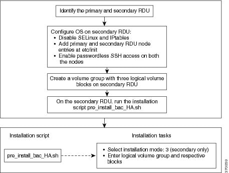
  1. On both primary and secondary RDU nodes, a logical volume group must be created with three logical volumes on it. The logical volumes are created based on the following specifications:

    • <logical volume for Prime Cable Provisioning install directory> - Mounted on /bprHome directory. For example, LVBPRHOME.

    • <logical volume for Prime Cable Provisioning data directory> - Mounted on /bprData directory. For example, LVBPRDATA

    • <logical volume for Prime Cable Provisioning log directory > - Mounted on /bprLog directory. For example, LVBPRDBLOG

  2. Ensure that the /bprData, /bprHome, and /bprLog directories are empty.

  3. The logical volumes should be of same capacity on both the nodes with a pre-created xfs filesystem.

Requirements for Proper Synchronization between Nodes

  • Identify the virtual IP address that can be used to locate both servers. Ensure that this virtual IP address is not configured for any physical interfaces in the network infrastructure. Also, this virtual IP address must belong to the network cluster in which you configure the primary and secondary RDU nodes.

  • In PCP Geo redundancy solution the VIP can be in any subnet

  • Identify the network IP addresses for public and private interface to configure dual ring support. For more information on dual ring support, see Cisco Prime Cable Provisioning User Guide.

  • The Network Time Protocol (NTP) must be synchronized between primary and secondary RDU nodes.

  • Both RDU nodes must exist in the same network cluster. This ensures that the same virtual IP address can be used to reach both the RDU nodes.

  • Both RDU nodes must be configured with the following two network interfaces:

    • Public access - Used for external communication. The DPE, REST PWS, CPNR_EP, and API clients use this interface to communicate with the RDU. A public IP address is configured to access this network interface.

    • Failover link between RDU nodes - Used for disk synchronization. If the RDU nodes are co-located, the failover link can be a crossover link, else the failover link must be configured in the private LAN. The failover IP addresses for primary and secondary nodes must be unique in the network cluster. This is to achieve the high speed access between primary and secondary RDU nodes, and also make them isolated from the network traffic.

Miscellaneous Requirements

  • To enable RDU HA notifications support, ensure that the SMTP server is configured. For more information on RDU HA notifications, see Cisco Prime Cable Provisioning User Guide.

  • Both RDU nodes must be configured with Gigabyte network interfaces.

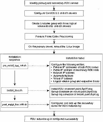
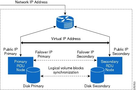
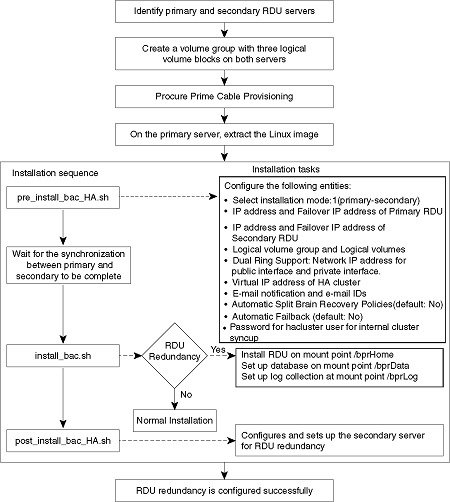
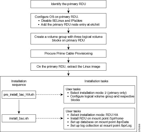
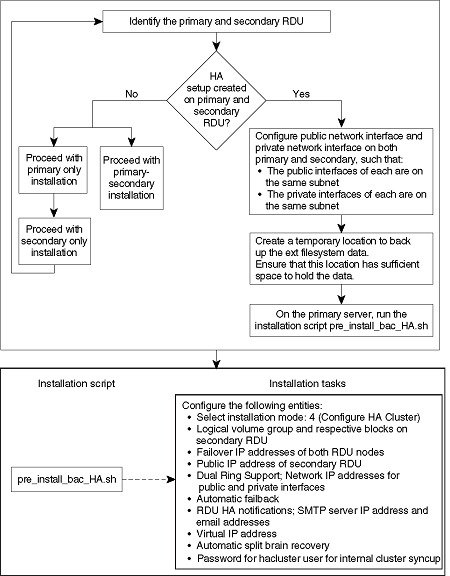
The following figure provides a high level RDU HA setup.

Figure 2. RDU HA Setup

RDU HA Installation Modes

In Prime Cable Provisioning, you can configure RDU HA setup using the following installation modes:
  • Primary-Secondary – Used to configure the RDU HA setup with both the primary and secondary nodes available in the network infrastructure.

  • Primary Only – Used to create the RDU HA setup only on the primary node. You can deploy the secondary RDU node in future, and configure the RDU HA cluster.

  • Secondary Only – Used to create the RDU HA setup only on the secondary node. After the RDU HA setup is created on primary and secondary nodes, you can configure the RDU HA cluster.

  • Configure HA – Used to configure the RDU HA cluster if the cluster is HA ready.

  • Recovery – Used to recover an impacted (corrupted) RDU node in the HA cluster.

Common Initial Steps for Configuring RDU HA Nodes

The configuration of RDU HA nodes involves some common initial steps, irrespective of the mode of installation. You can perform these initial steps on primary RDU server, secondary RDU server or both the servers, based on the mode of installation. You can then proceed with specific installation steps as defined in other topics.

Procedure


Step 1

Login to the RDU server as root.

Step 2

Modify the config file to disable SELinux using the following command:

# vi /etc/selinux/config

where, config file controls the state of SELinux on the system. In this file, set the value of SELINUX to disabled.

Step 3

Enter the host details of RDU node using the following command:

# vi /etc/hosts

The host details involve the public IP addresses, FQDN and short name of primary RDU node.

Step 4

Disable iptables on the RDU node:

# systemctl stop firewalld.service

Step 5

Verify if the iptables are disabled:

# systemctl status firewalld.service

Step 6

Reboot the RDU server:

# reboot

Step 7

Verify if the SELinux is disabled:

# /usr/sbin/sestatus

RDU HA Setup in Primary-Secondary Mode

If both primary and secondary RDU nodes are available in the network infrastructure, you can use primary-secondary installation mode to configure HA cluster.

To configure the RDU HA setup using primary-secondary installation mode, you must perform the following tasks sequentially:
  1. Configure RDU nodes for HA setup

  2. Set up RDU two node failover pair

The following figure describes the workflow for configuring RDU HA setup using primary-secondary installation mode.
Figure 3. RDU HA Setup - primary-secondary mode

Preparing RDU Nodes for HA Setup in Primary-Secondary Mode

Before installing the RDU redundancy function, you must perform the required server configurations and establish a communication channel between primary and secondary RDU servers.

To prepare primary and secondary RDU nodes for HA setup:

Procedure


Step 1

Log into the primary and secondary RDU servers as root.

Step 2

Modify the config file to disable SELinux using the following command:

# vi /etc/selinux/config

where, config file controls the state of SELinux on the system. In this file, set the value of SELINUX to disabled.

Step 3

Enter the host details of RDU nodes on both primary and secondary servers using the following command:

# vi /etc/hosts
127.0.0.1 localhost localhost.localdomain localhost4 localhost4.localdomain4
::1 localhost localhost.localdomain localhost6 localhost6.localdomain6
10.104.182.92 <rdu-primary>.cisco.com <rdu-primary>
10.104.182.93 <rdu-secondary>.cisco.com <rdu-secondary>

Note


The host details involve the public IP addresses, FQDNs and short names of RDU nodes.

The host details should not involve the failover ip address.

Step 4

Disable ip tables on both the RDU nodes using the following command:

# systemctl stop firewalld.service
# systemctl disable firewalld.service

Step 5

Verify if the ip tables are disabled using the following command:

# systemctl status firewalld.service

Step 6

Reboot both primary and secondary RDU servers using the following command:

# reboot

Step 7

Verify if the SELinux is disabled using the following command:

# /usr/sbin/sestatus

Step 8

Perform the steps on both the primary and secondary RDU nodes as described in Common Initial Steps for Configuring RDU HA Nodes.

Step 9

Configure the SSH access between primary and secondary RDU nodes and disable the password authentication:

  1. On the primary RDU node, run the following command to create the SSH keys:

    # ssh-keygen -t rsa -f ~/.ssh/id_rsa -N ""
    The system generates the SSH keys as follows:
    Generating public/private rsa key pair.
    Your identification has been saved in /root/.ssh/id_rsa.
    Your public key has been saved in /root/.ssh/id_rsa.pub.
    The key fingerprint is:
    SHA256:WGmpP4lHBg6wyjDPlQ8LFhqdTQ6RqcQQx4eFccKFras root@<rdu primary>
    The key's randomart image is:
    +---[RSA 2048]----+
    |*=O/=            |
    | *@O+.   o       |
    |=.+o* . =        |
    |+*.o * *         |
    |..o.. = S        |
    |  .    = .       |
    | .    . =        |
    |E      . .       |
    |                 |
    +----[SHA256]-----+
  2. Copy the SSH keys to the secondary RDU node:

    # # ssh-copy-id -i ~/.ssh/id_rsa.pub root@<rdu-primary/secondary>
    The system prompts you to enter the password for secondary RDU node. Once you enter the password, the system copies the SSH keys to the secondary RDU node:
    /usr/bin/ssh-copy-id: INFO: Source of key(s) to be installed: "/root/.ssh/id_rsa.pub"
    The authenticity of host '<rdu-secondary> (10.65.125.53)' can't be established.
    ECDSA key fingerprint is SHA256:C5vHIqW4ZqfBJ2QeNPgm+w1E42/FSxwfbxxCXRL3b60.
    Are you sure you want to continue connecting (yes/no)? yes
    /usr/bin/ssh-copy-id: INFO: attempting to log in with the new key(s), to filter out any that are already installed
    /usr/bin/ssh-copy-id: INFO: 1 key(s) remain to be installed -- if you are prompted now it is to install the new keys
    root@<rdu-secondary>'s password:
    
    Number of key(s) added: 1
    
    Now try logging into the machine, with:   "ssh 'root@pcp-lnx-23'"
    and check to make sure that only the key(s) you wanted were added.
  3. On the primary and secondary RDU servers, verify if the SSH access is available without password authentication:

    # ssh <target RDU server> -- uname -a

    where, <target RDU server> is the server name of primary or secondary RDU. For example, <rdu-primary> or <rdu-secondary>. If you verify the SSH access from primary RDU, you must enter the secondary RDU as the <target RDU server>.

    The following output confirms that SSH access is enabled between primary and secondary RDU nodes:

    Linux <target RDU server> 4.18.0-240.22.1.el8_3.x86_64 #1 SMP Thu Apr 8 19:01:30 UTC 2021
     x86_64 x86_64 x86_64 GNU/Linux

Step 10

Verify if the network access is available and the ethernet links are functioning normal:

# ifconfig
The following output confirms that the network access is available:
eth0 Link encap:Ethernet HWaddr 00:0C:29:ED:AE:75
            inet addr:10.104.182.92 Bcast:10.104.182.255 Mask:255.255.255.0
            inet6 addr: fe80::20c:29ff:feed:ae75/64 Scope:Link
            UP BROADCAST RUNNING MULTICAST MTU:1500 Metric:1
            RX packets:761 errors:0 dropped:0 overruns:0 frame:0
            TX packets:272 errors:0 dropped:0 overruns:0 carrier:0
            collisions:0 txqueuelen:1000
            RX bytes:66998 (65.4 KiB) TX bytes:41753 (40.7 KiB)

eth1        Link encap:Ethernet HWaddr 00:0C:29:ED:AE:7F
            inet addr:192.168.1.1 Bcast:192.168.1.255 Mask:255.255.255.0
            inet6 addr: fe80::20c:29ff:feed:ae7f/64 Scope:Link
            UP BROADCAST RUNNING MULTICAST MTU:1500 Metric:1
            RX packets:6 errors:0 dropped:0 overruns:0 frame:0
            TX packets:13 errors:0 dropped:0 overruns:0 carrier:0
            collisions:0 txqueuelen:1000
            RX bytes:360 (360.0 b) TX bytes:830 (830.0 b)
lo          Link encap:Local Loopback
            inet addr:127.0.0.1 Mask:255.0.0.0
            inet6 addr: ::1/128 Scope:Host
            UP LOOPBACK RUNNING MTU:16436 Metric:1
            RX packets:0 errors:0 dropped:0 overruns:0 frame:0
            TX packets:0 errors:0 dropped:0 overruns:0 carrier:0
            collisions:0 txqueuelen:0
            RX bytes:0 (0.0 b) TX bytes:0 (0.0 b)

Step 11

Verify the accessibility between primary and secondary RDU nodes:

  • Ping secondary RDU node from the primary server:

    # ping <rdu-secondary>

  • Ping primary RDU node from the secondary server:

    # ping <rdu-primary>

Step 12

Make sure servers have internet connectivity to download packages from Rocky Linux Repo.

Step 13

Enable ELRepo to install DRBD packages.

  1. Import the public key:

    # rpm --import https://www.elrepo.org/RPM-GPG-KEY-elrepo.org
  2. To install ELRepo for RHEL/Rocky-8:

    # dnf install https://www.elrepo.org/elrepo-release-8.el8.elrepo.noarch.rpm

For Rocky Linux 8.10, enable a High Availability repository (Rocky-HighAvailability.repo).

For RHEL 8.10, enable the Red Hat subscription on RHEL 8 and then enable a High Availability repository to download the cluster packages from Red Hat.

Step 14

Note


For Geo setup in RHEL 8.10, RHEL EPEL repository should be enabled to install the frr package.

Configure the repository for Geo setup.

Copy and save the following as frr-7.repo in /etc/yum.repos.d :

[frr]
name=FRRouting 7.x Packages for Enterprise Linux 8 - $basearch
baseurl=https://rpm.frrouting.org/repo/el8/frr7
enabled=1
gpgcheck=1
gpgkey=file:///etc/pki/rpm-gpg/RPM-GPG-KEY-FRR

[frr-RPKI]
name=FRRouting 7.x Packages with RPKI for Enterprise Linux 8 - $basearch
baseurl=https://rpm.frrouting.org/repo/el8/frr-rpki
enabled=0
gpgcheck=1
gpgkey=file:///etc/pki/rpm-gpg/RPM-GPG-KEY-FRR

[frr-extras]
name=FRRouting Dependencies for Enterprise Linux 8 - $basearch
baseurl=https://rpm.frrouting.org/repo/el8/extras
enabled=1
gpgcheck=1
gpgkey=file:///etc/pki/rpm-gpg/RPM-GPG-KEY-FRR

Setting Up RDU Two Node Failover Pair

The RDU two node failover pair setup involves running three installation scripts sequentially on the primary RDU. The following table describes each installation script and the sequence in which you run them.
Table 1. RDU Two Node Failover Pair Setup
Sequence Installation Scripts Description
1 pre_install_bac_HA.sh
Used to configure the following entities:
  • Installation mode: 1 (primary-secondary)

  • Logical volume group and logical volumes

  • Failover IP addresses of both the RDU nodes

  • Network IP address

  • Dual ring support; Network IP addresses for public and private interfaces

  • Automatic failback

  • RDU HA notifications; Email addresses of the recipients to receive RDU HA cluster notifications

  • Virtual IP address

  • Secondary RDU server public IP address

  • Automatic split brain recovery

  • Utilities required for RDU redundancy function setup.

  • Password for hacluster user.

2 install_bac.sh Used to install the RDU component on the logical volumes.
3 post_install_bac_HA.sh Used to automate the supported configuration tasks for RDU redundancy function setup.

To set up the RDU two node failover pair:

Procedure


Step 1

Log into the primary RDU as root.

Step 2

Extract the installation package using the following commands:

gunzip -d BAC_74_LinuxK9.gtar.gz
gtar -xzvf BAC_74_LinuxK9.gtar

The utility creates the BAC_74_LinuxK9 directory into which the installation program is extracted.

Step 3

Run the preinstallation script using the following command:

# sh pre_install_bac_HA.sh

Step 4

Select the installation mode 1 (primary-secondary) to configure the RDU HA cluster with both primary and secondary nodes available in the network infrastructure.

Step 5

Enter the RDU redundancy information. The RDU redundancy information includes:

  • Failover IP addresses of primary and secondary RDU servers - Unique IP address in the network cluster that are used for data synchronization between primary and secondary RDU nodes.

  • Public IP address of the secondary RDU - Public IP address that is used for external communication.

Step 6

Enter the name of the logical volume group. For example, VGBPR.

Step 7

Enter the name of the logical volumes created for home, data, and database log directories. For example, you can enter LVBPRHOME for home directory, LVBPRDATA for data directory, and LVBPRDBLOG for database log directory.

Step 8

Enter the network IP address of the subnet under which both the RDU cluster nodes exist.

Step 9

Enter the network IP addresses for both public and private interfaces of the RDU cluster nodes. The Network IP address (public) is configured for the network ring on public interface, and the Network IP address (private) is configured for the network ring on private interface. For more information on dual ring configuration, see Cisco Prime Cable Provisioning 7.4 User Guide.

Step 10

Enter the virtual IP address. The virtual IP address is the floating IP address that is used to reach both primary and secondary RDU nodes, but allocated to only active RDU node. Ensure that this virtual IP address is not configured for any physical interfaces in the network.

  • For PCP Geo redundancy solution the CIDR value of VIP should be 32.

Step 11

For PCP Geo redundancy solution (i.e if both the servers are on different subnet) enter "y" to advertise VIP using frr, else enter "n" .

  • If VIP advertisement through frr is enabled then enter the interface through which you want to advertise the VIP, by default it is ens, make sure this interface name is same on both primary and secondary servers, also make sure this interface is connected to the ingress router where route injection is done.

  • If VIP advertisement through frr is disabled then enter the CIDR value for VIP.

Step 12

Enter y to enable automatic failback, else enter n. If the automatic failback is enabled, the primary RDU node becomes active once it comes up after the failover event.

The preinstallation script performs the following automated operations on both primary and secondary RDU nodes:
  • Installs the utilities for RDU redundancy setup.

  • Creates the required resources for synchronizing the block devices.

Step 13

Enter valid password to set and authenticate hacluster user, for internal communication between cluster servers.

Step 14

Enter n to disable RDU HA email notifications, the default value is y.

To configure email notifications, you must:
  1. configure the following properties in /etc/postfix/main.cf file:

    • relay_domains = <SMTP_IPaddress> or <Domain_name_address>

    • relayhost = <SMTP_IPaddress> or <Domain_name_address>

  2. enter the email addresses of the recipients to receive the HA cluster notifications. The email addresses of multiple recipients are configured using comma separated list.

Note


You can also enter a valid email alias to trigger RDU HA email notifications to a dedicated group of recipients.

The email notifications are triggered for the following events:
  • Primary or secondary RDU node changes its state during the failover or failback occurrence

  • CRM resources become unresponsive or changes its state

  • Split brain occurrence

Step 15

Enter y to enable the automatic split brain recovery. For information on split brain recovery policies, see Cisco Prime Cable Provisioning 7.4 User Guide.

Note

 
Even though both automatic failback and automatic split brain recovery are enabled, some of the data may be discarded to ensure automatic recovery from the split brain situation.

The preinstallation script performs the following automated operations on both primary and secondary RDU nodes:
  • Installs the utilities for RDU redundancy setup.

  • Creates the required resources for synchronizing the block devices.

Step 16

Install RDU on the synchronized logical volumes; LVBPRHOME, LVBPRDATA, and LVBPRDBLOG. For details, see Installing the RDU in Interactive Mode.

Step 17

Run the post-installation script available under BAC_74_LinuxK9 directory:

# sh post_install_bac_HA.sh

The post-installation script performs the automated configuration tasks required for RDU redundancy function setup.


RDU HA Setup in Primary-Only and Secondary-Only Modes

Prime Cable Provisioning provides you the flexibility to first deploy the primary RDU node with HA setup ready, and later deploy the secondary RDU node and create the RDU HA cluster.

To configure the RDU HA setup using primary only and secondary only modes, you must perform the following tasks sequentially:
  1. Create RDU HA setup on the primary node.

  2. Create RDU HA setup on the secondary node.

  3. Configure the cluster for HA.

Configuring RDU Node in Primary-Only Mode

The primary only installation mode helps you to create the HA setup on the primary RDU node. You can deploy the secondary RDU node at a later stage, and configure the HA setup without impacting the primary node configuration.

The following figure provides the workflow to create the HA setup on primary RDU node.
Figure 4. RDU HA Setup on Primary Node

To create the HA setup on primary RDU node:

Procedure


Step 1

Perform the steps on the primary RDU node as described in Common Initial Steps for Configuring RDU HA Nodes.

Step 2

Extract the installation package:

gtar -xzvpf BAC_74_LinuxK9.gtar

The utility creates the BAC_74_LinuxK9 directory into which the installation program is extracted.

Step 3

Run the preinstallation script:

# sh pre_install_bac_HA.sh

Step 4

Select the installation mode as 2 (primary only).

Step 5

Enter the name of the logical volume group. For example, VGBPR.

Step 6

Enter the name of the logical volumes created for home, data, and database log directories. For example, you can enter LVBPRHOME for home directory, LVBPRDATA for data directory, and LVBPRDBLOG for database log directory.

The preinstallation script performs the following automated operations on both primary RDU nodes:
  • Installs the utilities for RDU redundancy setup, and stops them.

  • Removes chkconfig entries for configuring the utilities.

  • Formats all the LVBs using ext4.

Step 7

Install RDU on the synchronized logical volumes - LVBPRHOME, LVBPRDATA, and LVBPRDBLOG. For details, see Installing the RDU in Interactive Mode.


Configuring RDU Node in Secondary-Only Mode

The secondary-only installation mode helps you to create the HA setup on secondary RDU node. You can proceed with this installation mode if you have identified the primary node and it meets the prerequisites. The secondary RDU node is deployed to configure the RDU two node failover pair.

The following figure provides the workflow to create the HA setup on secondary RDU node.
Figure 5. RDU HA Setup on Secondary Node

To create the HA setup on secondary RDU node:

Procedure


Step 1

Check whether the primary RDU node is already identified and it meets the prerequisites.

Step 2

Perform the steps on the secondary RDU node as described in Common Initial Steps for Configuring RDU HA Nodes.

Step 3

Configure the SSH access between primary and secondary RDU nodes and disable the password authentication:

  • Create the SSH keys, on the secondary RDU node, :
    # ssh-keygen -t dsa -f ~/.ssh/id_dsa -N ""
  • Copy the SSH keys to the primary RDU node:
    # cp ~/.ssh/id_dsa.pub ~/.ssh/authorized_keys
    # scp -r ~/.ssh <rdu-primary>:
    The system prompts you to enter the password for primary RDU node. Once you enter the password, the system copies the SSH keys to the primary RDU node:
    root@<rdu-primary>'s password:
    known_hosts
    100% 1199 1.2KB/s 00:00
    id_dsa.pub
    100% 606 0.6KB/s 00:00
    id_dsa
    100% 668 0.7KB/s 00:00
# /usr/sbin/sestatus

Step 4

Verify if the SSH access is available without password authentication, on the primary and secondary RDUs:

# ssh <target RDU server> -- uname –n

where, <target RDU server> is the server name of primary or secondary RDU server. For example, <rdu-primary> or <rdu-secondary>. If you verify the SSH access from primary RDU server, you must enter the secondary RDU server as the <target RDU server>.

The following output confirms that SSH access is enabled between primary and secondary RDU nodes:
Linux <target RDU server> 3.10.0-693.11.6.x86_64 #1 SNP Wed Jun 13 18:24:36 EDT
2012
x86_64 x86_64 x86_64 GNU/Linux

Step 5

Extract the installation package:

gtar -xzvpf BAC_74_LinuxK9.gtar.gz

The utility creates the BAC_74_LinuxK9 directory into which the installation program is extracted.

Step 6

Run the preinstallation script:

# sh pre_install_bac_HA.sh

Step 7

Select the installation mode as 3 (secondary only).

Step 8

Enter the name of the logical volume group. For example, VGBPR.

Step 9

Enter the name of the logical volume blocks created for home, data, and database log directories. For example, you can enter LVBPRHOME for home directory, LVBPRDATA for data directory, and LVBPRDBLOG for database log directory.

Note


In case of secondary only installation, the preinstallation script restricts mounting of LVBs on home, data, and DBlog directories.

The preinstallation script performs the following automated operations on secondary RDU node:
  • Installs the utilities for RDU redundancy setup.

  • Creates the required resources for synchronizing the block devices.

  • Adds the chkconfig entries for configuring the utilities.

  • Formats all the LVBs using xfs only on secondary node.


Configuring HA Cluster from an RDU HA Ready Installation

If the installation is HA Ready (the primary server is successfully set up with the Primary Only mode), you can configure the HA cluster. You can run the installation script pre_install_HA_bac.sh and choose the installation mode 4 (configure HA) to configure the required resources and synchronize the primary and secondary RDU nodes.

The following figure provides the workflow for configuring the RDU two node failover pair.
Figure 6. Configure HA Cluster

To configure the HA cluster:

Procedure


Step 1

Check whether the RDU HA setup is created on primary RDU using the primary-only mode. For information on how to create the HA setup, see Configuring RDU Node in Primary-Only Mode.

Step 2

Check whether both the nodes (primary and secondary) have one public network interface each, configured in the same subnet; and one private network interface each, configured in the same subnet (different from the previous subnet).

Step 3

Create a temporary location on the primary RDU where you can back up the xfs filesystem data. Ensure that the appropriate space is available in the temporary location to store the existing file system data.

Note


When you configure the RDU HA cluster, the xfs filesystem on primary RDU server is overwritten with DRBD filesystem. The installation mode 4 (configure HA) facilitates you to back up the xfs filesystem data and store it in a temporary location. This data is further restored after the DRBD filesystem is created on primary RDU server.

Step 4

Log into the primary RDU node as root, and run the installation script pre_install_bac_HA.sh.

Step 5

Select the installation mode 4 (configure HA).

Step 6

Enter the temporary location to back up the xfs filesystem data.

Step 7

Enter the RDU redundancy information. The RDU redundancy information includes:

  • Failover IP addresses of primary and secondary RDU servers - Unique IP address in the network cluster that are used for data synchronization between primary and secondary RDU nodes.

  • Public IP address of the secondary RDU server - Public IP address that is used for external communication.

Step 8

Enter the name of the logical volume group. For example, VGBPR.

Step 9

Enter the name of the logical volumes created for home, data, and database log directories. For example, you can enter LVBPRHOME for home directory, LVBPRDATA for data directory, and LVBPRDBLOG for database log directory.

Step 10

Enter the network IP address for both public and private interfaces of the RDU cluster nodes. The Network IP address (public) is configured for the network ring on public interface, and the Network IP address (private) is configured for the network ring on private interface. For more information on dual ring configuration, see Cisco Prime Cable Provisioning User Guide.

Step 11

Enter the virtual IP address. The virtual IP address is the floating IP address that is used to reach both primary and secondary RDU nodes, but allocated to only active RDU node. Ensure that this virtual IP address is not configured for any physical interfaces in the network.

Step 12

Enter y to enable RDU HA email notifications. To configure email notifications, you must:

  • Configure the following properties in /etc/postfix/main.cf file:

    • relay_domains = <SMTP_IPaddress> or <Domain_name_address>

    • relayhost = <SMTP_IPaddress> or <Domain_name_address>

  • Enter the email addresses of the recipients to receive the HA cluster notifications. The email addresses of multiple recipients are configured using comma separated list.

    Note


    You can also enter a valid email alias to trigger RDU HA email notifications to a dedicated group of recipients.

The email notifications are triggered for the following events:
  • Primary or Secondary RDU node changes its state during the failover or failback occurrence

  • CRM resources become unresponsive or changes its state

  • Split brain occurrence

Step 13

Enter y to enable automatic failback, else enter n. If the automatic failback is enabled, the primary RDU node becomes active once it comes up after the failover event.

Step 14

Enter y to enable the automatic split brain recovery. For information on split brain recovery policies, see Cisco Prime Cable Provisioning User Guide.

The pre_install_bac_HA.sh script performs the following automated operations on both primary and secondary RDU nodes:
  • Installs the utilities for RDU redundancy setup.

  • Creates the required resources for synchronizing the block devices.

  • Adds the chkconfig entries for configuring the utilities.

Step 15

Enter valid password to set and authenticate hacluster user. For internal communication between cluster servers.

Step 16

Run the post-installation script available under BAC_74_LinuxK9 directory:

# sh post_install_bac_HA.sh

The post-installation script performs the automated configuration tasks required for RDU redundancy function setup.


Recovering an Impacted RDU Node Using Recovery Mode

If any of the RDU nodes in the HA cluster gets corrupted, you can recover the impacted RDU node using the recovery mode. The recovery mode facilitates you to synchronize the impacted RDU node with the active RDU node, and restore the corrupted filesystem data.

To recover the impacted RDU node:

Procedure


Step 1

Ensure the following:

  • The impacted RDU node conforms to the required prerequisites and that the initial configuration is set up. For details, see Prerequisites and Common Initial Steps for Configuring RDU HA Nodes.
  • SSH is also configured on the impacted node, with password authentication disabled.
  • The public network interface and the private network interface of the impacted node are configured with the same IP address as before.

Step 2

Log into the impacted RDU node as root, and run the installation script pre_install_bac_HA.sh.

Step 3

Select the recovery mode 5.

Step 4

Enter the public IP address of the active RDU node.

Step 5

Enter the name of the logical volume group.

Step 6

Enter the name of the logical volumes created on /bprHome, /bprData, and /bprLog directories.

Once the synchronization of the filesystem is completed, the impacted RDU node gets reconnected to the RDU HA cluster.


RDU HA Uninstall Scripts

To uninstall the RDU HA setup in the primary and secondary RDU nodes, you must run the uninstall scripts sequentially. The following table describes the uninstall scripts and the sequence in which you run them.

Table 2. Uninstall RDU HA Setup
Sequence Uninstall Scripts Description
1 uninstall_bac.sh Used to unistall the RDU component from the logical volume blocks; /bprHome, /bprData, and /bprLog. For details, see Uninstalling Prime Cable Provisioning.
2 uninstall_bac_HA.sh Used to remove the utilities installed for RDU redundancy function.

Remove VIP from primary server after successful completion of uninstall_bac_HA.sh using the following command.

ip -f inet addr del VIP/CIDR value brd netmask value dev interface name

ex: ip -f inet addr del 10.10.2.1/32 brd 255.255.255.255 dev lo


Note


In the RDU HA cluster:
  • If you want to uninstall the RDU HA setup created only on the primary RDU node, run the uninstall_bac.sh and uninstall_bac_HA.sh sequentially on the primary RDU node as described in Table 1.

  • If you want to uninstall the RDU HA setup created only on the secondary RDU node, run the uninstall_bac_HA.sh on the secondary RDU server.


RDU Geo Redundancy

RDU Geo Redundancy is an enhanced feature of RDU HA supported on RHEL 8.10 or Rocky Linux 8.10 with kernel(4.18.0-553) (both 64bit), wherein the RDU primary and secondary node can be in different geographical location or both the nodes can be in different subnet.

  • In Geo redundancy mode the VIP can be in any subnet it is not necessary to have in the subnet range common to both nodes.

  • In Geo redundancy mode the CIDR value of VIP should be 32.

  • The VIP will be advertised as a RIP advertisement from the active server, so on the ingress router of both the nodes route injection need to be done.

For setting up RDU in Geo redundancy mode follow steps mentioned in Setting Up RDU Redundancy