User Guide for Cisco Network Registrar 7.2
Bias-Free Language
The documentation set for this product strives to use bias-free language. For the purposes of this documentation set, bias-free is defined as language that does not imply discrimination based on age, disability, gender, racial identity, ethnic identity, sexual orientation, socioeconomic status, and intersectionality. Exceptions may be present in the documentation due to language that is hardcoded in the user interfaces of the product software, language used based on RFP documentation, or language that is used by a referenced third-party product. Learn more about how Cisco is using Inclusive Language.
- Updated:
- March 20, 2015
Chapter: Network Registrar Components
Cisco Network Registrar Components
Cisco Network Registrar provides the tools to configure and control the servers necessary to manage your IP address space. This chapter provides an overview of the management components and concentrates on the Trivial File Transfer Protocol (TFTP) and Simple Network Management Protocol (SNMP), which are not covered in subsequent parts of this User Guide.
Management Components
Cisco Network Registrar contains two management components:
•![]() Regional component, consisting of:
Regional component, consisting of:
–![]() Web-based user interface (web UI)
Web-based user interface (web UI)
–![]() Command line interface (CLI)
Command line interface (CLI)
–![]() Central Configuration Management (CCM) server to provide to local cluster, address space, and router management
Central Configuration Management (CCM) server to provide to local cluster, address space, and router management
•![]() Local component, consisting of:
Local component, consisting of:
–![]() Web UI
Web UI
–![]() CLI
CLI
–![]() CCM server
CCM server
–![]() Domain Name System (DNS) server
Domain Name System (DNS) server
–![]() Dynamic Host Configuration Protocol (DHCP) server
Dynamic Host Configuration Protocol (DHCP) server
–![]() Trivial File Transport Protocol (TFTP) server
Trivial File Transport Protocol (TFTP) server
–![]() Simple Network Management Protocol (SNMP) server
Simple Network Management Protocol (SNMP) server
–![]() Router Interface Configuration (RIC) server
Router Interface Configuration (RIC) server
–![]() Management of local address space, zones, scopes, DHCPv6 prefixes and links, and users
Management of local address space, zones, scopes, DHCPv6 prefixes and links, and users
The remainder of this chapter describes the TFTP and SNMP protocols. The CCM server, web UIs, and CLI are described in Chapter 2, "Cisco Network Registrar User Interfaces." The DNS, DHCP, and RIC servers are described in their respective sections of this manual.
Trivial File Transfer
The Trivial File Transfer Protocol (TFTP) is a way of transferring files across the network using the User Datagram Protocol (UDP), a connectionless TCP/IP transport layer protocol. Cisco Network Registrar maintains a TFTP server so that systems can provide device provisioning files to cable modems that comply with the Data Over Cable Service Interface Specification (DOCSIS) standard. The TFTP server buffers the DOCSIS file in its local memory as it sends the file to the modem. After a TFTP transfer, the server flushes the file from local memory. TFTP also supports non-DOCSIS configuration files.
Here are some of the features of the Cisco Network Registrar TFTP server:
•![]() Complies with RFCs 1123, 1350, 1782, and 1783
Complies with RFCs 1123, 1350, 1782, and 1783
•![]() Includes a high performance multithreaded architecture
Includes a high performance multithreaded architecture
•![]() Supports IPv6
Supports IPv6
•![]() Caches data for performance enhancements
Caches data for performance enhancements
•![]() Is configurable and controllable in the web UI and using the tftp command in the CLI
Is configurable and controllable in the web UI and using the tftp command in the CLI
•![]() Includes flexible path and file access controls
Includes flexible path and file access controls
•![]() Includes audit logging of TFTP connections and file transfers
Includes audit logging of TFTP connections and file transfers
•![]() Has a default root directory in the Cisco Network Registrar install-path/data/tftp
Has a default root directory in the Cisco Network Registrar install-path/data/tftp
See Also
Viewing and Editing the TFTP Server
Managing the TFTP Server Network Interfaces
Viewing and Editing the TFTP Server
At the local cluster, you can edit the TFTP server to modify its attributes. You must be assigned the server-management subrole of the ccm-admin role.
Local Basic or Advanced Web UI
Step 1 ![]() From the Administration drop-down list, choose Manage Servers to open the Manage Servers page (see the "Managing Servers" section on page 7-1).
From the Administration drop-down list, choose Manage Servers to open the Manage Servers page (see the "Managing Servers" section on page 7-1).
Step 2 ![]() Click the Local TFTP Server link to open the Edit TFTP Server page.
Click the Local TFTP Server link to open the Edit TFTP Server page.
Step 3 ![]() Values for the attributes marked with asterisks are required for TFTP server operation. You can click the name of any attribute to open a description window for the attribute.
Values for the attributes marked with asterisks are required for TFTP server operation. You can click the name of any attribute to open a description window for the attribute.
Step 4 ![]() To unset any attribute value, click the check box in the Unset? column, then click Unset Fields at the bottom of the page. To modify values you change or unset, click Modify Server, or Cancel to cancel the changes.
To unset any attribute value, click the check box in the Unset? column, then click Unset Fields at the bottom of the page. To modify values you change or unset, click Modify Server, or Cancel to cancel the changes.
CLI Commands
Use tftp to show the attribute values. Use tftp set attribute=value or tftp enable attribute to set or enable attributes. You can also use tftp serverLogs show, and tftp serverLogs nlogs=number logsize=size.
Managing the TFTP Server Network Interfaces
You can manage the network interfaces for the TFTP server.
Local Advanced Web UI
Manage the network interfaces associated with the TFTP server by clicking the icon in the Interfaces column of the TFTP server on the Manage Servers page. You can view the default configured network interfaces, and create and edit additional ones. To create and edit them, you must be assigned the server-management subrole of the ccm-admin role.
The columns on the Manage TFTP Server Network Interface page are:
•![]() Name—Name of the network interface, such as the LAN adapter, loopback, and Fast Ethernet interfaces. If the name is under the Configured Interfaces column, you can edit and delete the interface. Clicking the name opens the Edit TFTP Server Network Interface page so that you can edit the interface name and addresses. Make changes, then click Modify Interface on this page.
Name—Name of the network interface, such as the LAN adapter, loopback, and Fast Ethernet interfaces. If the name is under the Configured Interfaces column, you can edit and delete the interface. Clicking the name opens the Edit TFTP Server Network Interface page so that you can edit the interface name and addresses. Make changes, then click Modify Interface on this page.
•![]() IP Address—IP address of the network interface.
IP Address—IP address of the network interface.
•![]() IPv6 Address—IPv6 address, if applicable, of the network interface.
IPv6 Address—IPv6 address, if applicable, of the network interface.
•![]() Flags—Flags for whether the interface should be zero-broadcast, virtual, v4, v6, no-multicast, or receive-only.
Flags—Flags for whether the interface should be zero-broadcast, virtual, v4, v6, no-multicast, or receive-only.
•![]() Configure—To configure a new network interface, click the Configure icon next to the interface name. This creates another interface based on the one selected, but with a more general IP address, and adds this interface to the Configured Interfaces for this TFTP Server.
Configure—To configure a new network interface, click the Configure icon next to the interface name. This creates another interface based on the one selected, but with a more general IP address, and adds this interface to the Configured Interfaces for this TFTP Server.
•![]() Configured Interfaces for this TFTP Server—User-configured network interfaces, showing each name and associated address. Click the interface name to edit it, or click the Delete icon to delete it.
Configured Interfaces for this TFTP Server—User-configured network interfaces, showing each name and associated address. Click the interface name to edit it, or click the Delete icon to delete it.
To return to managing the server, click Return.
CLI Commands
Use the tftp-interface commands.
Simple Network Management
The Cisco Network Registrar Simple Network Management Protocol (SNMP) notification support allows you to query the DHCP and DNS counters, be warned of error conditions and possible problems with the DNS and DHCP servers, and monitor threshold conditions that can indicate failure or impending failure conditions.
Cisco Network Registrar implements SNMP Trap Protocol Data Units (PDUs) according to the SNMPv2c standard. Each trap PDU contains:
•![]() Generic-notification code, if enterprise-specific.
Generic-notification code, if enterprise-specific.
•![]() A specific-notification field that contains a code indicating the event or threshold crossing that occurred.
A specific-notification field that contains a code indicating the event or threshold crossing that occurred.
•![]() A variable-bindings field that contains additional information about certain events.
A variable-bindings field that contains additional information about certain events.
Refer to the Management Information Base (MIB) for the details. The SNMP server supports only reads of the MIB attributes. Writes to the attributes are not supported.
The following MIB files are required:
•![]() Traps—CISCO-NETWORK-REGISTRAR-MIB.my
Traps—CISCO-NETWORK-REGISTRAR-MIB.my
•![]() DNS server—CISCO-DNS-SERVER-MIB.my
DNS server—CISCO-DNS-SERVER-MIB.my
•![]() DHCPv4 server—CISCO-IETF-DHCP-SERVER-MIB.my
DHCPv4 server—CISCO-IETF-DHCP-SERVER-MIB.my
•![]() DHCPv4 server capability—CISCO-IETF-DHCP-SERVER-CAPABILITY.my
DHCPv4 server capability—CISCO-IETF-DHCP-SERVER-CAPABILITY.my
•![]() DHCPv4 server extensions—CISCO-IETF-DHCP-SERVER-EXT-MIB.my
DHCPv4 server extensions—CISCO-IETF-DHCP-SERVER-EXT-MIB.my
•![]() DHCPv4 server extensions capability—CISCO-IETF-DHCP-SERVER-EXT-CAPABILITY.my
DHCPv4 server extensions capability—CISCO-IETF-DHCP-SERVER-EXT-CAPABILITY.my
•![]() DHCPv6 server—CISCO-NETREG-DHCPV6-MIB.my (experimental)
DHCPv6 server—CISCO-NETREG-DHCPV6-MIB.my (experimental)

Note ![]() A new MIB, CISCO-NETREG-DHCPV6-MIB is defined to support query of new DHCP v6 related statistics and new DHCP v6 traps.
A new MIB, CISCO-NETREG-DHCPV6-MIB is defined to support query of new DHCP v6 related statistics and new DHCP v6 traps.
These MIB files are available in the /misc directory of the Cisco Network Registrar installation path.
The following URL includes all files except the experimental CISCO-NETREG-DHCPV6-MIB.my file:
ftp://ftp.cisco.com/pub/mibs/supportlists/cnr/cnr-supportlist.html
The following dependency files are also required:
•![]() Dependency for DHCPv4 and DHCPv6—CISCO-SMI.my
Dependency for DHCPv4 and DHCPv6—CISCO-SMI.my
•![]() Additional dependencies for DHCPv6—INET-ADDRESS-MIB.my
Additional dependencies for DHCPv6—INET-ADDRESS-MIB.my
These dependency files are available along with all the MIB files at the following URL:
ftp://ftp.cisco.com/pub/mibs/v2/
To get the object identifiers (OIDs) for the MIB attributes, go to the equivalently named .oid file at:
ftp://ftp.cisco.com/pub/mibs/oid/
See Also
Setting Up the SNMP Server
How Notification Works
Handling SNMP Notification Events
Handling SNMP Queries
Setting Up the SNMP Server
To perform queries to the SNMP server, you need to set up the server properties.
Local Basic or Advanced Web UI
Step 1 ![]() From the Administration drop-down list, choose Manage Servers to open the Manage Servers page (see the "Managing Servers" section on page 7-1).
From the Administration drop-down list, choose Manage Servers to open the Manage Servers page (see the "Managing Servers" section on page 7-1).
Step 2 ![]() Click the Local SNMP Server link to open the Edit SNMP Server page.
Click the Local SNMP Server link to open the Edit SNMP Server page.
Step 3 ![]() The Community string attribute is the password to access the server. (The community string is a read community string only.) The preset value is public.
The Community string attribute is the password to access the server. (The community string is a read community string only.) The preset value is public.
Step 4 ![]() You can specify log settings and other miscellaneous and advanced options:
You can specify log settings and other miscellaneous and advanced options:
•![]() trap-source-addr—Optional sender address to use for outgoing traps.
trap-source-addr—Optional sender address to use for outgoing traps.
•![]() server-active—Determines whether the SNMP server is active for queries. The default value is true. If set to false, the server will run, but is not accessible for queries and does not send out traps.
server-active—Determines whether the SNMP server is active for queries. The default value is true. If set to false, the server will run, but is not accessible for queries and does not send out traps.
•![]() cache-ttl—Determines how long the SNMP caches responds to queries, default to 60 seconds.
cache-ttl—Determines how long the SNMP caches responds to queries, default to 60 seconds.
Step 5 ![]() To manage the SNMP server interfaces, click List Interfaces (or select Advanced mode and click the icon in the Interfaces column of the SNMP server on the Manage Servers page). You can view the default configured network interfaces, and create and edit additional ones. To create and edit them, you must be assigned the server-management subrole of the ccm-admin role. The interface properties are similar to those for the TFTP server (see the "Managing the TFTP Server Network Interfaces" section).
To manage the SNMP server interfaces, click List Interfaces (or select Advanced mode and click the icon in the Interfaces column of the SNMP server on the Manage Servers page). You can view the default configured network interfaces, and create and edit additional ones. To create and edit them, you must be assigned the server-management subrole of the ccm-admin role. The interface properties are similar to those for the TFTP server (see the "Managing the TFTP Server Network Interfaces" section).
Step 6 ![]() To manage trap recipients for the server:
To manage trap recipients for the server:
a. ![]() Click List Trap Recipients to open the List/Add Trap Recipients page.
Click List Trap Recipients to open the List/Add Trap Recipients page.
b. ![]() Enter the name and IP address of a trap recipient (both are required).
Enter the name and IP address of a trap recipient (both are required).
c. ![]() Click Add Trap Recipient.
Click Add Trap Recipient.
d. ![]() Repeat for each additional trap recipient.
Repeat for each additional trap recipient.
e. ![]() To set the port, community string, and agent address for a trap recipient, click its name on the List/Add Trap Recipients page to open the Edit Trap Recipient page, then set the values.
To set the port, community string, and agent address for a trap recipient, click its name on the List/Add Trap Recipients page to open the Edit Trap Recipient page, then set the values.
f. ![]() Click Modify Recipient.
Click Modify Recipient.
Step 7 ![]() Complete the SNMP server setup by clicking Modify Server.
Complete the SNMP server setup by clicking Modify Server.
CLI Commands
To set the community string in the CLI so that you can access the SNMP server, use snmp set community=name. Use snmp set trap-source-addr to set the trap source address. Use snmp disable server-active to deactivate the SNMP server, and snmp set cache-ttl=time to set the cache time-to-live.
To set trap recipients, use trap-recipient, in the following syntax to include the IP address:
nrcmd> trap-recipient name create ip-addr=ip-addr
You can also add the agent-address, community, and port-number values for the trap recipient.
Other SNMP-related commands include snmp disable server-active to prevent the server from running when started, and the snmp-interface commands to configure the interfaces. The addr-trap command is described in the "Handling SNMP Notification Events" section.
How Notification Works
Cisco Network Registrar SNMP notification support allows a standard SNMP management station to receive notification messages from the DHCP and DNS servers. These messages contain the details of the event that triggered the SNMP trap.
Cisco Network Registrar generates notifications in response to predetermined events that the application code detects and signals. Each event can also carry with it a particular set of parameters or current values. For example, the free-address-low-threshold event can occur in the scope with a value of 10% free. Other scopes and values are also possible for such an event, and each type of event can have different associated parameters.
Table 1-1 describes the events that can generate notifications.
Handling SNMP Notification Events
When Cisco Network Registrar generates a notification, it transmits a single copy of the notification as an SNMP Trap PDU to each recipient. All events (and scopes or prefixes) share the list of recipients and other notification configuration data, and the server reads them when you initialize the notification.
You can set SNMP attributes in three ways:
•![]() For the DHCP server, which includes the traps to enable and the default free-address trap configuration if you are not specifically configuring traps for scopes or prefixes (or their templates).
For the DHCP server, which includes the traps to enable and the default free-address trap configuration if you are not specifically configuring traps for scopes or prefixes (or their templates).
•![]() On the scope or prefix (or its template) level by setting the free-address-config attribute.
On the scope or prefix (or its template) level by setting the free-address-config attribute.
•![]() For the DNS server, which includes a traps-enabled setting.
For the DNS server, which includes a traps-enabled setting.
To use SNMP notifications, you must specify trap recipients that indicate where trap notifications should go. By default, all notifications are enabled, but you must explicitly define the recipients, otherwise no notifications can go out. The IP address you use is often localhost.
The DHCP server provides special trap configurations so that it can send notifications, especially about free addresses for DHCPv4 and DHCPv6. You can set the trap configuration name, mode, and percentages for the low threshold and high threshold. The mode determines how scopes aggregate their free-address levels.
DHCPv4 Notification
The DHCPv4 modes and thresholds are (see also the "Handling Deactivated Scopes or Prefixes" section):
•![]() scope mode—Causes each scope to track its own free-address level independently (the default).
scope mode—Causes each scope to track its own free-address level independently (the default).
•![]() network mode—Causes all scopes set with this trap configuration (through the scope or scope template free-address-config attribute) to aggregate their free-address levels if the scopes share the same primary-subnet.
network mode—Causes all scopes set with this trap configuration (through the scope or scope template free-address-config attribute) to aggregate their free-address levels if the scopes share the same primary-subnet.
•![]() selection-tags mode—Causes scopes to aggregate their free-address levels if they share a primary subnet and have a matching list of selection tag values.
selection-tags mode—Causes scopes to aggregate their free-address levels if they share a primary subnet and have a matching list of selection tag values.
•![]() low-threshold—Free-address percentage at which the DHCP server generates a low-threshold trap and re-enables the high threshold. The free-address level for scopes is the following calculation:
low-threshold—Free-address percentage at which the DHCP server generates a low-threshold trap and re-enables the high threshold. The free-address level for scopes is the following calculation:
100 * available-nonreserved-leases
total-configured-leases
•![]() high-threshold—Free-address percentage at which the DHCP server generates a high-threshold trap and re-enables the low threshold.
high-threshold—Free-address percentage at which the DHCP server generates a high-threshold trap and re-enables the low threshold.
DHCPv6 Notification
The DHCPv6 modes and thresholds are (see also the "Handling Deactivated Scopes or Prefixes" section):
•![]() prefix mode—Causes each prefix to track its own free-address level independently.
prefix mode—Causes each prefix to track its own free-address level independently.
•![]() link mode—Causes all prefixes configured for the link to aggregate their own free-address levels if all prefixes share the same link.
link mode—Causes all prefixes configured for the link to aggregate their own free-address levels if all prefixes share the same link.
•![]() v6-selection-tags mode—Causes prefixes to aggregate their free-address levels if they share a link and have a matching list of selection tag values.
v6-selection-tags mode—Causes prefixes to aggregate their free-address levels if they share a link and have a matching list of selection tag values.
•![]() low-threshold—Free-address percentage at which the DHCP server generates a low-threshold trap and re-enables the high threshold. The free-address level for prefixes is the following calculation:
low-threshold—Free-address percentage at which the DHCP server generates a low-threshold trap and re-enables the high threshold. The free-address level for prefixes is the following calculation:
100 * max-leases - dynamic-leases
max-leases
•![]() high-threshold—Free-address percentage at which the DHCP server generates a high-threshold trap and re-enables the low threshold.
high-threshold—Free-address percentage at which the DHCP server generates a high-threshold trap and re-enables the low threshold.
Handling Deactivated Scopes or Prefixes
A deactivated scope or prefix never aggregates its counters with other scopes or prefixes. For example, if you configure a prefix with link or v6-selection-tags trap mode, and then deactivate the prefix, its counters disappear from the total count on the aggregation. Any changes to the leases on the deactivated prefix do not apply to the aggregate totals.
Therefore, to detect clients for deactivated scopes or prefixes, you must set the event mode to scope or prefix, and not to any of the aggregate modes (network, selection-tags, link, or v6-selection-tags).
The use case for setting traps on deactivated prefixes, for example, is network renumbering. In this case, you might want to monitor both the new prefixes (as an aggregate, ensuring that you have enough space for all the clients) and old prefixes to ensure that their leases are freed up. You would probably also want to set the high threshold on an old prefix to 90% or 95%, so that you get a trap fired when most of its addresses are free.
Local Basic or Advanced Web UI
Access the SNMP attributes for the DHCP server by choosing Manage Servers from Administration drop-down list, then the Local DHCP Server link on the Manage Servers page. The SNMP attributes are about two-thirds down the Edit DHCP Server page (see Figure 1-1).
Figure 1-1 SNMP Attributes on the Edit DHCP Server Page (Local)
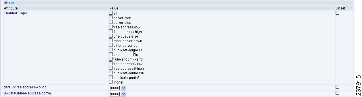
The four lease-enabled values (free-address6-low, free-address6-high, duplicate-address6, duplicate-prefix6) pertain to DHCPv6 only. Along with the traps to enable, you can specify the default free-address trap configuration by name, which affects all scopes and prefixes or links not explicitly configured.
To add a trap configuration, do the following:
Step 1 ![]() Choose Traps from the DHCP menu to access the DHCP trap configurations in Advanced mode. The List Trap Configurations page appears.
Choose Traps from the DHCP menu to access the DHCP trap configurations in Advanced mode. The List Trap Configurations page appears.
Step 2 ![]() Enter the name, mode, and threshold percentages in the List Trap Configurations page, then click Add Trap Configuration.
Enter the name, mode, and threshold percentages in the List Trap Configurations page, then click Add Trap Configuration.
To edit a trap configuration, do the following:
Step 1 ![]() Click the desired trap name on the List Trap Configurations page, and modify the name, mode, or threshold percentages on the Edit Trap Configuration page.
Click the desired trap name on the List Trap Configurations page, and modify the name, mode, or threshold percentages on the Edit Trap Configuration page.
Step 2 ![]() Check the on check box for enabled attribute to enable the trap configuration.
Check the on check box for enabled attribute to enable the trap configuration.
To delete a trap configuration, click the Delete icon ( ) next to the name, then confirm or cancel the deletion.
Regional Basic or Advanced Web UI
In the regional web UI, you can add and edit trap configurations as in the local web UI. You can also pull replica trap configurations and push trap configurations to the local cluster on the List Trap Configurations page.
Server Up/Down Traps
Every down trap must be followed by a corresponding up trap. However, this rule is not strictly applicable in the following scenarios:
1. ![]() If a failover partner or LDAP server or DNS server or HA DNS partner is down for a long time, down traps will be issued periodically. An up trap will be generated only when that server or partner returns to service.
If a failover partner or LDAP server or DNS server or HA DNS partner is down for a long time, down traps will be issued periodically. An up trap will be generated only when that server or partner returns to service.
2. ![]() If the DHCP or DNS server is reloaded or restarted, the prior state of the partner or related servers is not retained and duplicate down or up traps can result.
If the DHCP or DNS server is reloaded or restarted, the prior state of the partner or related servers is not retained and duplicate down or up traps can result.
Note ![]() Other failover partner or LDAP server or DNS server or HA DNS partner up or down traps occur only to communicate with that partner or server, and therefore may not occur when the other partner or server goes down or returns to service.
Other failover partner or LDAP server or DNS server or HA DNS partner up or down traps occur only to communicate with that partner or server, and therefore may not occur when the other partner or server goes down or returns to service.
CLI Commands
To set the trap values for the DHCP server at the local cluster, use dhcp set traps-enabled=value. You can also set the default-free-address-config attribute to the trap configuration. For example:
nrcmd> dhcp set traps-enabled=server-start,server-stop,free-address-low,free-address-high
nrcmd> dhcp set default-free-address-config=v4-trap-config
Note ![]() If you do not define a default-free-address-config (or v6-default-free-address-config for IPv6), Cisco Network Registrar creates an internal, unlisted trap configuration named default-aggregation-addr-trap-config. Because of this, avoid using that name for a trap configuration you create.
If you do not define a default-free-address-config (or v6-default-free-address-config for IPv6), Cisco Network Registrar creates an internal, unlisted trap configuration named default-aggregation-addr-trap-config. Because of this, avoid using that name for a trap configuration you create.
To define trap configurations for DHCPv4 and DHCPv6, use addr-trap name create followed by the attribute=value pairs for the settings. For example:
nrcmd> addr-trap v4-trap-conf create mode=scope low-threshold=25% high-threshold=30%
nrcmd> addr-trap v6-trap-conf create mode=prefix low-threshold=20% high-threshold=25%
Handling SNMP Queries
You can use SNMP client applications to query the following MIBs:
•![]() CISCO-DNS-SERVER-MIB.my
CISCO-DNS-SERVER-MIB.my
•![]() CISCO-IETF-DHCP-SERVER-MIB.my
CISCO-IETF-DHCP-SERVER-MIB.my
•![]() CISCO-IETF-DHCP-SERVER-EXT-MIB.my
CISCO-IETF-DHCP-SERVER-EXT-MIB.my
•![]() CISCO-NETREG-DHCPV6-MIB.my (experimental)
CISCO-NETREG-DHCPV6-MIB.my (experimental)
When the SNMP server receives a query for an attribute defined in one of these MIBs, it returns a response PDU containing that attribute value. For example, using the NET-SNMP client application (available over the Internet), you can use one of these commands to obtain a count of the DHCPDISCOVER packets for a certain address:
C:\net-snmp5.2.2\bin>snmpget -m ALL -v 2c -c public
192.168.241.39:4444.iso.org.dod.internet.private.enterprises.cisco.ciscoExperiment.
ciscoIetfDhcpSrvMIB.ciscoIetfDhcpv4SrvMIBObjects.cDhcpv4Counters.cDhcpv4CountDiscovers
CISCO-IETF-DHCP-SERVER-MIB::cDhcpv4CountDiscovers = Counter32: 0
C:\net-snmp5.2.2\bin>snmpget -m ALL -v 2c -c public
192.168.241.39:4444 1.3.6.1.4.1.9.10.102.1.3.1
CISCO-IETF-DHCP-SERVER-MIB::cDhcpv4CountDiscovers = Counter32: 0
Both commands return the same results. The first one queries the full MIB attribute name, while the second one queries its OID equivalent (which can be less error prone). As previously described, the OID equivalents of the MIB attributes are located in the relevant files at the following URL:
ftp://ftp.cisco.com/pub/mibs/oid/
For example, the CISCO-IETF-DHCP-SERVER-MIB.oid file includes the following OID definition that corresponds to the previous query example:
"cDhcpv4CountDiscovers" "1.3.6.1.4.1.9.10.102.1.3.1"
Here are some possible SNMP query error conditions:
•![]() The community string sent in the request PDU does not match what you configured.
The community string sent in the request PDU does not match what you configured.
•![]() The version in the request PDU is not the same as the supported version (SNMPv2).
The version in the request PDU is not the same as the supported version (SNMPv2).
•![]() If the object being queried does not have an instance in the server, the corresponding variable binding type field is set to SNMP_NOSUCHINSTANCE. With a GetNext, if there is no next attribute, the corresponding variable binding type field is set to SNMP_ENDOFMIBVIEW.
If the object being queried does not have an instance in the server, the corresponding variable binding type field is set to SNMP_NOSUCHINSTANCE. With a GetNext, if there is no next attribute, the corresponding variable binding type field is set to SNMP_ENDOFMIBVIEW.
•![]() If no match occurs for the OID, the corresponding variable binding type field is set to SNMP_NOSUCHOBJECT. With a GetNext, it is set to SNMP_ENDOFMIBVIEW.
If no match occurs for the OID, the corresponding variable binding type field is set to SNMP_NOSUCHOBJECT. With a GetNext, it is set to SNMP_ENDOFMIBVIEW.
•![]() If there is a bad value returned by querying the attribute, the error status in the response PDU is set to SNMP_ERR_BAD_VALUE.
If there is a bad value returned by querying the attribute, the error status in the response PDU is set to SNMP_ERR_BAD_VALUE.
Default Ports for Cisco Network Registrar Services
Table 1-2 lists the default ports used for the Cisco Network Registrar services.
 Feedback