Deploying Cisco SD-WAN Services on MSX

This chapter details the procedures for deploying Cisco SD-WAN services on Cisco Managed Services Accelerator (MSX).

Deployment Workflow for Cisco SD-WAN

Using the workflow in the table below, you can deploy Cisco SD-WAN vEdge Cloud, or vEdge SP Cloud, or the Physical site.

Table 1. Workflow for Cisco SD-WAN vEdge Cloud, or vEdge SP Cloud, or Physcial Sites

Task

See

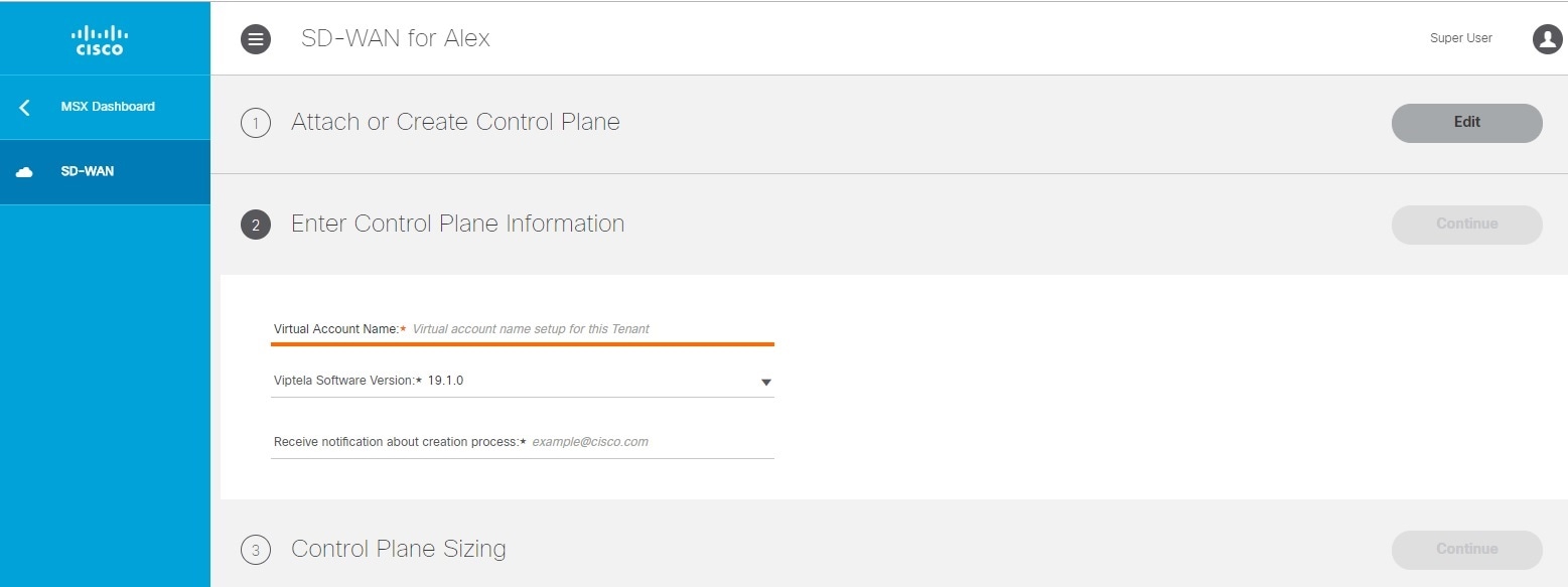
1. Attach an existing control plane or create a new control plane.

Setting Up Control and Management Plane on AWS and OpenStack for Cisco SD-WAN

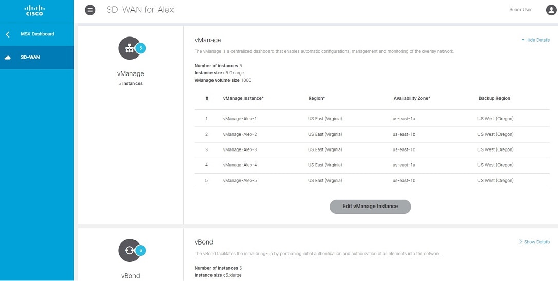
2. Complete Control Plane post deployment tasks.

For more information, see Postdeployment Tasks for SD-WAN Control Plane.

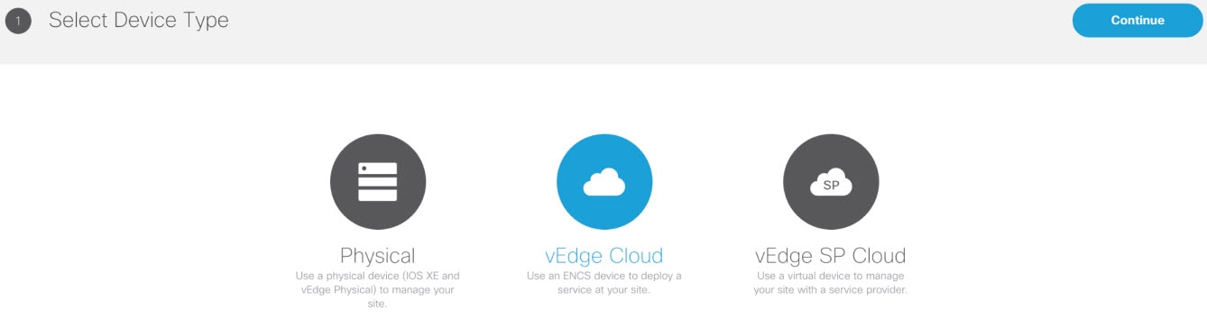
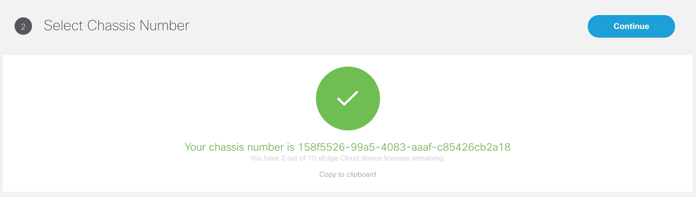
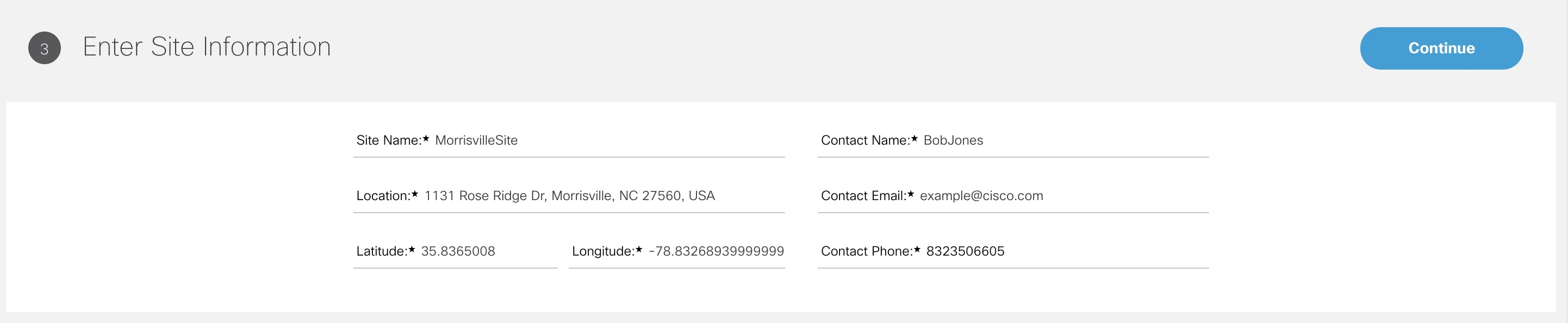
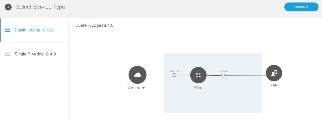
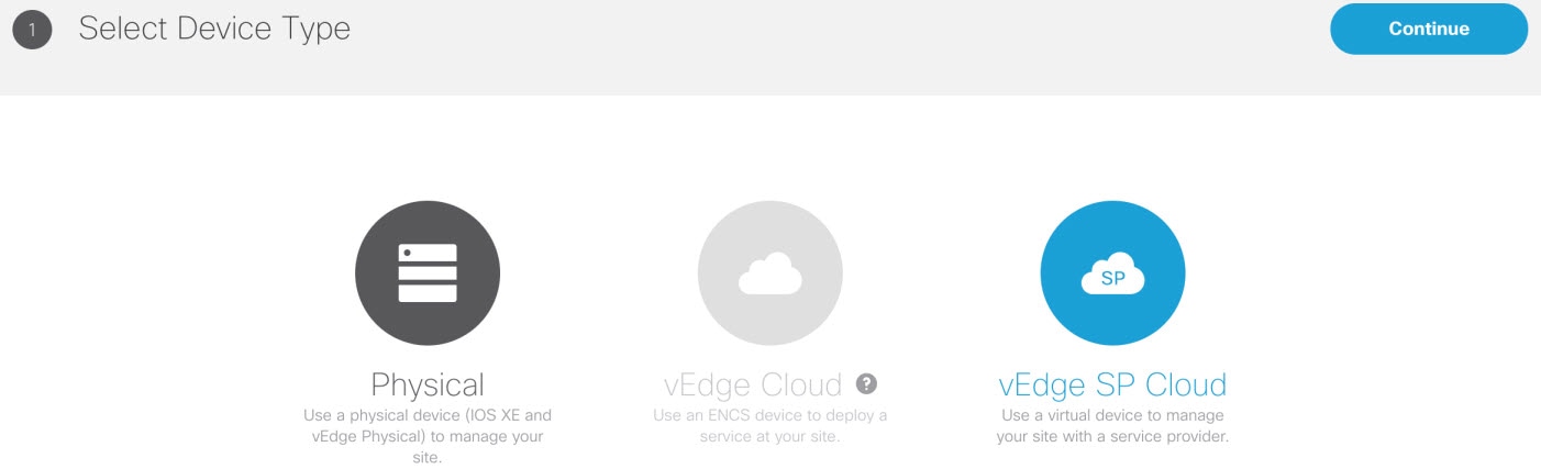
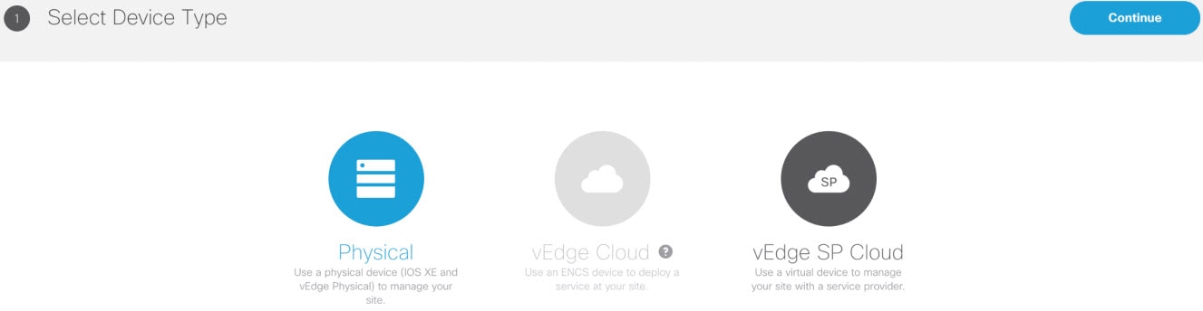
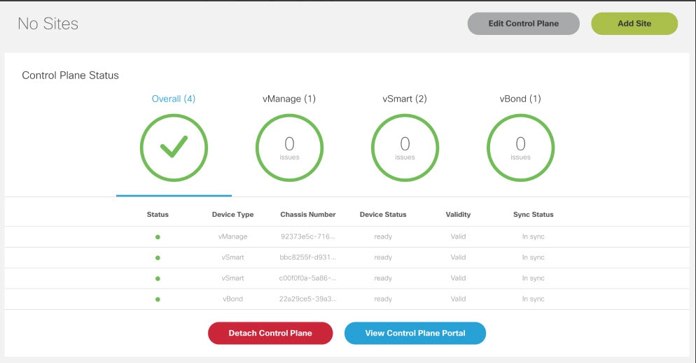
3. Add a vEdge Cloud or vEdge SP Cloud or a Physical Site/Device.

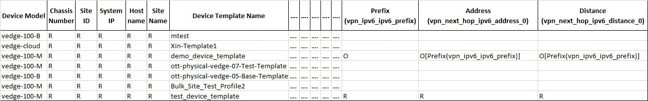
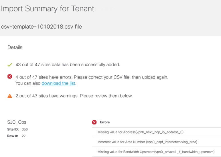
4. (Optional) If you have details of multiple sites available, you can import these details into MSX.

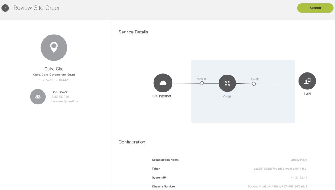
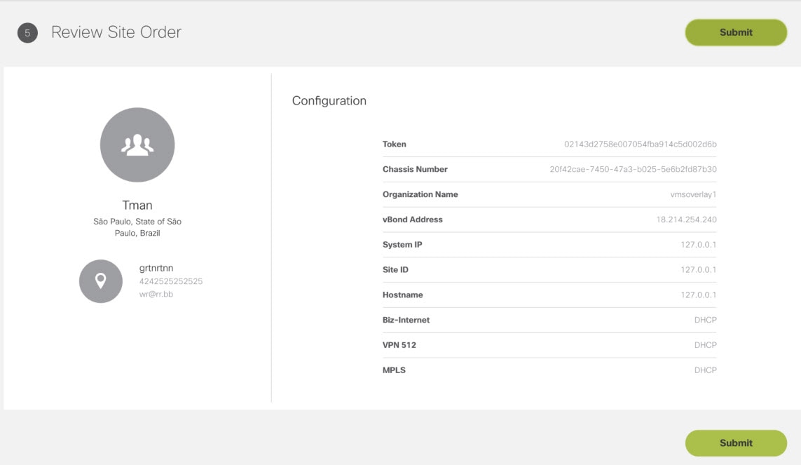
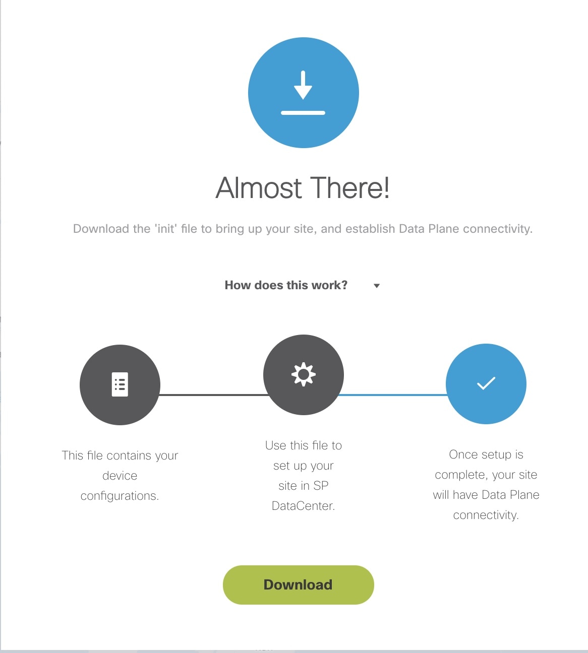
5. Push the site details to the Control Plane such that the device is set up for day one configurations.

Provisioning a Site for Cisco SD-WAN

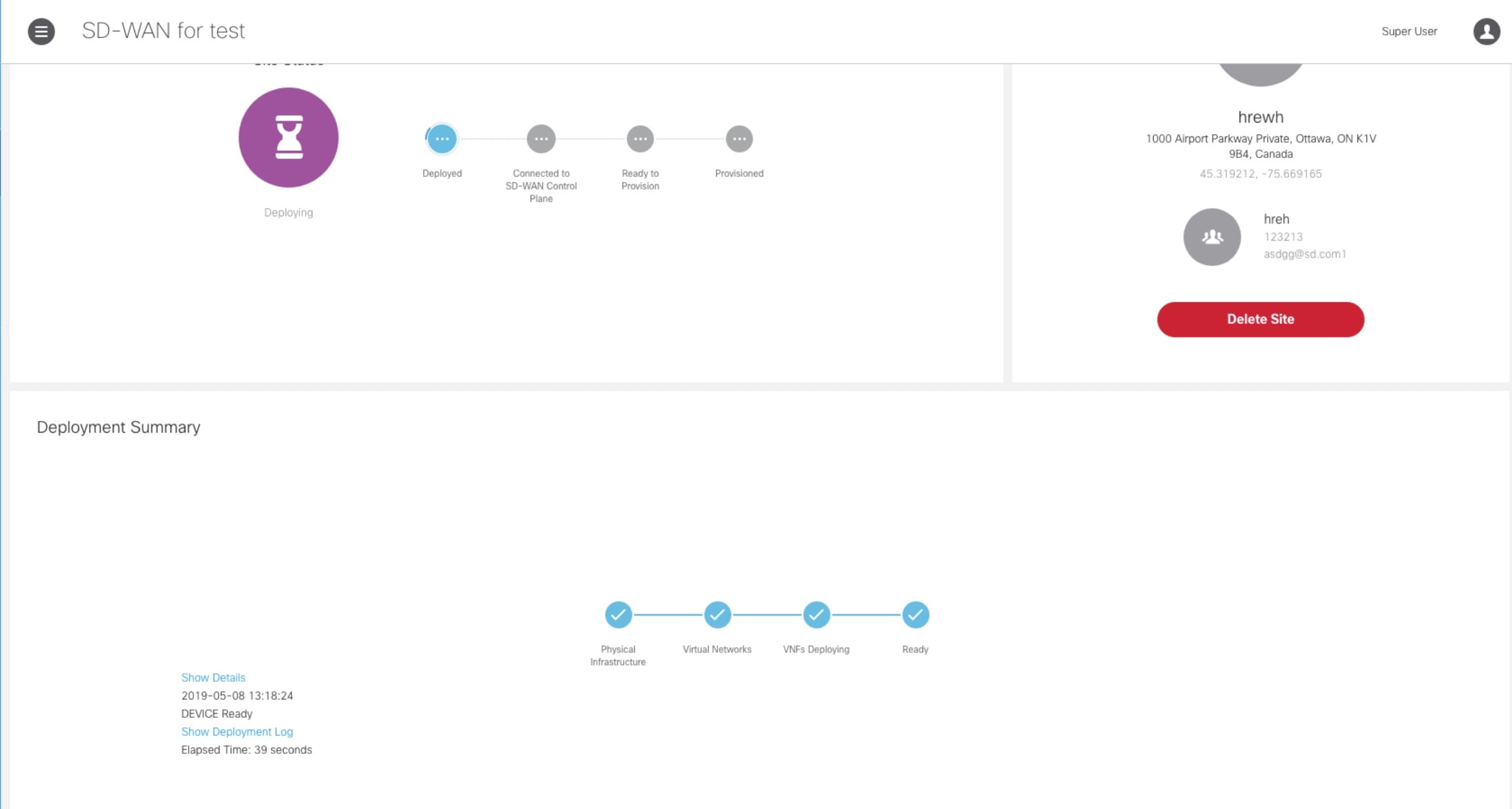
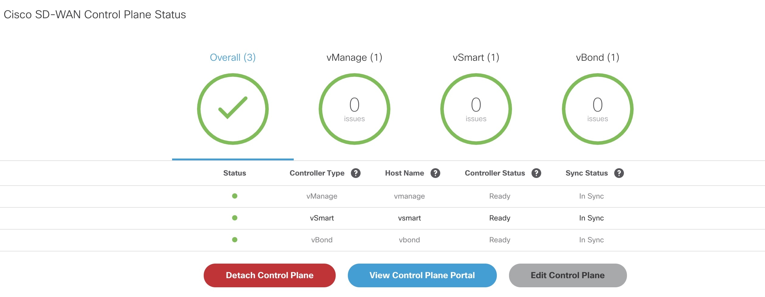
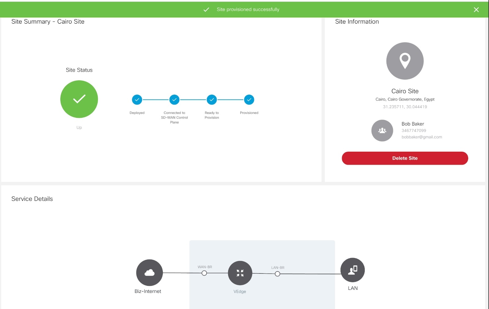
6. Verify all the components of SD-WAN service are deployed.

Verifying the Status of Cisco SD-WAN

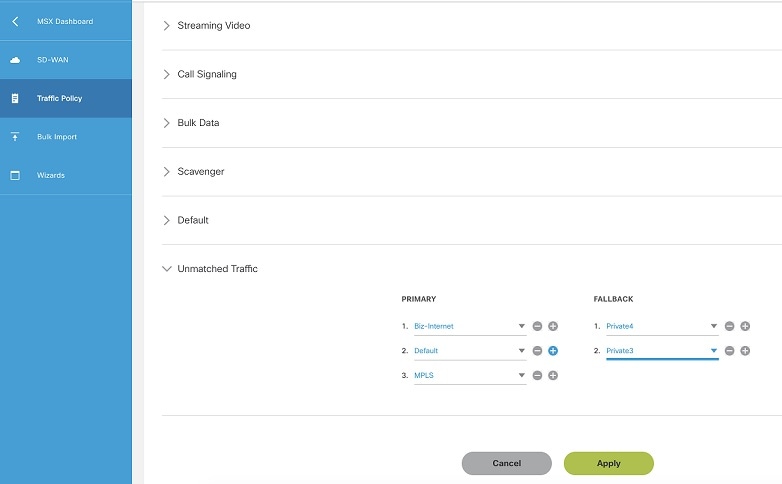
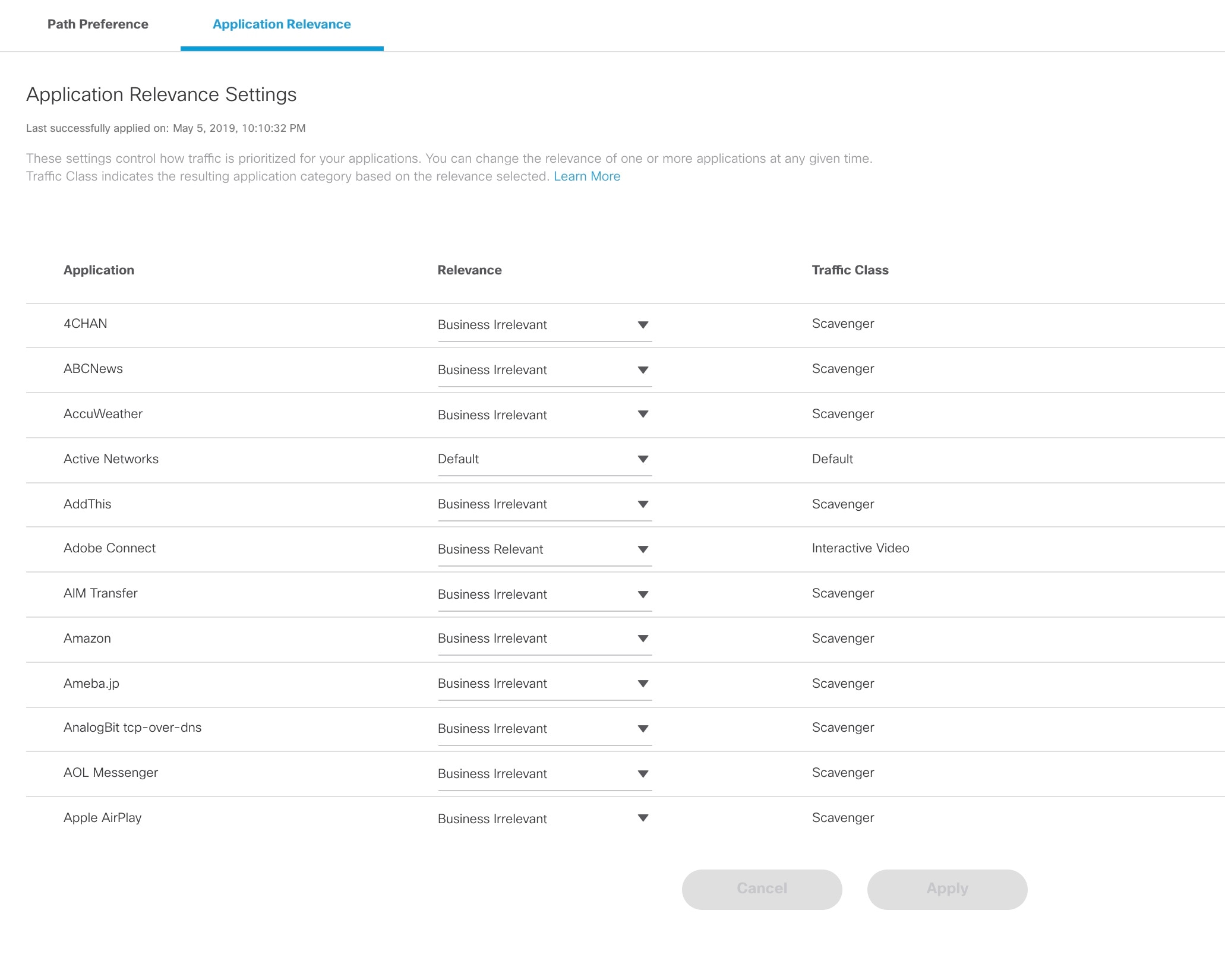
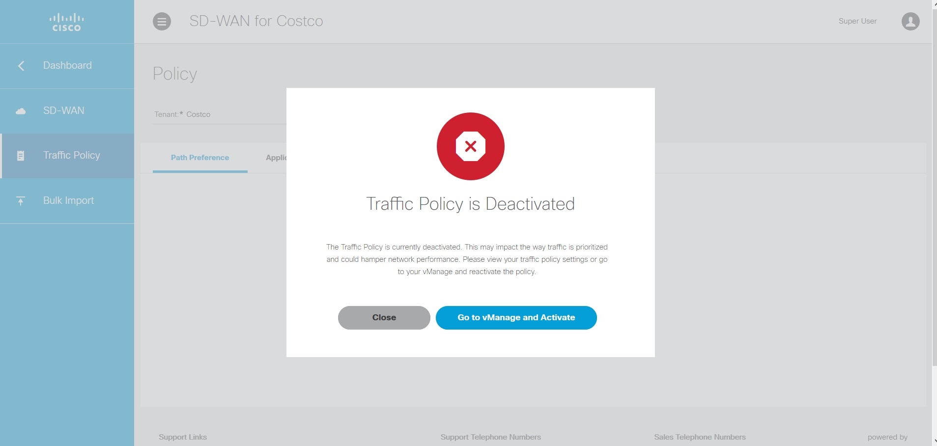
7. Configure Traffic Policies

Configuring SD-WAN Traffic Policies

Setting Up Control Plane for Cisco SD-WAN

The deployment of an SD-WAN service in the context of a managed service requires deployment per customer and includes the SD-WAN management control plane (vManage, vBond and vSmart), and the corresponding data plane (vEdge and cEdge).


Note

This section describes the steps required to set up MSX control plane on both AWS and OpenStack.

The following are the topics covered in this section:

Prerequisites for Setting Up Control Plane

The following section has common prerequisites as well as OpenStack and AWS-specific prerequisites for setting up Control Plane.

Control Plane Prerequisites for both AWS and OpenStack

The following are control plane prerequisites applicable for both AWS and OpenStack environment:

  • Contact Cisco Account representative for:

    • Setting up a Smart Account if you are a Service Provider, or you can request for a smart account here: https://software.cisco.com.

    • Creating a Virtual Account for a new tenant (Service Provider end customer) and associating it to the service provider smart account. A Virtual Account is necessary for every new SD-WAN tenant.

    • Requesting for Cisco SD-WAN orchestration stack environment. This is required to spin up control plane components on AWS.

    • Ordering physical devices and virtual devices through Cisco Commerce Workspace (CCW).

    • Associating the purchased devices to the Virtual Account.

      After devices are associated with your smart account, you can synchronize the device details on the Control Plane after setting the Control Plane. For more information, see Synchronizing Smart Accounts from the Control Plane.

  • Assign ‘SD-WAN Control Plane’ permission to the user who will create a Control Plane for the tenant. Along with the control plane permission, assign other SD-WAN permissions to the user managing SD-WAN services. For more information on the SD-WAN-specific permissions and to associate these permissions to a role, see Managing Cisco MSX SD-WAN Specific Roles in Cisco MSX .

  • Create a new SD-WAN tenant for the Service Provider end customer on MSX, see Managing Tenants and Managing Users.

  • If you have an SD-WAN deployment with vManage connected, your external certificates must be copied and imported into the centralized MSX keystore. Contact your Cisco representative to add your external certificates to MSX.

Control Plane Prerequisites Applicable Only For AWS

The following are control plane prerequisites for AWS:

  • Provide the SD-WAN orchestration settings to integrate MSX with Cisco SD-WAN orchestration stack. For more information, see Configuring Cisco SD-WAN Orchestrator Settings.

  • Add Cisco MSX and Tenants IP Subnets in the MSX Allowed List: For Cisco MSX to create SD-WAN Control Planes, it needs to be able to communicate with the Cisco SD-WAN Orchestration stack which is protected by secure IP. Do the following to add these IP to the allowed list in MSX:

    1. Determine the source IP addresses of an Cisco MSX deployment:

      • If Cisco MSX is installed on AWS: These are the NAT GW IP addresses. Go to VPC > NAT Gateway dashboard on your AWS console. There should be three IP addresses, one for each public subnet.

      • If Cisco MSX is installed on-prem: This will be proxy IP, if no proxy, then use the Cisco MSX public IP.

    2. Contact Cisco TAC, submit your tenant users IP subnet and request to add these to the allowed list on SD-WAN Orchestration Stack for HTTPS/443 port.


      Note

      If you use Cisco MSX to access the control plane, you do not have to add tenant's IPs to the allowed list as MSX connects to the control plane using an MSX-managed proxy. This functionality is not enabled by default and can be configured using an API. For more information, see Disabling MSX-Managed Proxy.

Control Plane Prerequisites Applicable Only For OpenStack

The following are control plane prerequisites for OpenStack:

  • You can customize Cisco MSX to create control plane in OpenStack environment. Leverage and deploy an ansible API playbook. This will install the additional OpenStack Orchestration (OSorch) micro-services in the Cisco MSX.

    1. Create flavors, these are hardware specifications such as vCPU, Root Disk, RAM, and so on. Provide the hardware details that are required for creating control plane on OpenStack.


      Note

      OS orchestration creates 100G (vManage) volume as part of the deployment
    2. Download the qcow images from the SD-WAN Cisco website (CCO) and upload it into OpenStack cloud.

  • To install the OS orchestrator from the deployer system, execute the following command:
    
    export ANSIBLE_VAULT_PASSWORD_FILE=/tmp/ansible-vault-password
    cd /msx-3.7.0/ansible/ 
    ansible-playbook -i inventory/inventory deploy-osorch.yml

Creating Control Plane on OpenStack

You need to specify the following attributes while creating SD-WAN control plane on OpenStack.

Table 2. Attributes Used in Creating SD-WAN Control Plane in OpenStack

Key Options of OS orchestrator

Explanation

Provider Network

  • Create a control plane using the existing network on OpenStack cloud.

  • The control plane is established using the existing subnets that are already provisioned on the Openstack cloud, it has dedicated subnets setup for different customers.

Tenant Network

  • Create a newly dedicated network for the customer.

  • Deploy the required VPN0, VPN512, and floating IPs on the OpenStack to create an SD-WAN control plane on OpenStack.

Note 
  • Ensure floating IP addresses are available for assignment to Viptela VMs. Each control plane requires six floating IP addresses (two per instance).

  • Additionally two more floating IPs are created for Openstack routers as part of Tenant network flow.

Multi-Tenant

  • Create an SD-WAN control plane on a dedicated tenant project space. This option is used both in provider and tenant network.

  • OS orchestrator supports creating instances on multi-tenant or project space on the OpenStack cloud.

Note 
Change the "projectName" and "projectID" values in the add vim payload to reflect the Tenant/Project space that is to be configured.

Enterprise Certificate Authentication (CA)

  • Cisco MSX automatically creates CA, then generates Certificate Signing Request (CSR).

  • Use this certificate to sign in. This is a part of deployment activity.

  • Thus, creates fully configured control plane instances that are ready for vEdge site deployment.

Note 
To select this option, include ‘createCA: true' in the create control plane payload.

Default Symantec/Cisco CA

  • Log in to vManage to generates CSR, and sign in using the CSR certificate for deploying the control plane.

  • Once you deploy the control plane instances state are moved 'Up'.

Note 
  • To select this option include ‘createCA: false' in the create control plane payload.

  • For the OpenStack network, use symantec as the default enterprise Root-Certificate Authentication (CA) to activate Viptela controller during the day0 configuration process.

  • To create a control plane on OpenStack environment, use curl command from Kubernetes-master mode.

    • The OS orchestrator requires authorization token, and to get the token use the following curl command:

      
      curl -k https://<MSX fqdn>/idm/api/v1/login -XPOST -d '{"username": "username
      ", "password": "<password
      >"}' -H 'content-type: application/json'
    • Enter authorization token as the value of the authorization parameter, as shown in the sample:

      This is an sample curl command for creating and deleting VIM:

      
      curl -H "Authorization: Bearer <token
      >" http://osorch.service.consul:8080/osorch/v1/vims -X POST -H "Content-Type: application/json" -d '<payload>'
      curl -H "Authorization: Bearer <token
      >" http://osorch.service.consul:8080/osorch/v1/vims -X DELETE -H "Content-Type: application/json" -d '<payload>'

      Note

      You can enter the valid values in <token> and <payload>.
  • This table below various APIs used in managing SD-WAN control plane on OpenStack.

Table 3. Tasks involved in Creating SD-WAN Control Plane

Request Type

API

Description

Create VIM


POST /osorch/v1/vims
  • You can choose either the Provider network or Tenant network based on the OpenStack cloud requirement.

  • Make API call using curl command. Ensure that you copy the ID that is obtained as response, as the ID is needed to create the CP payload.

Delete VIM


DELETE /osorch/v1/vims/{vimID}

Use the given API in the DELETE job and monitor the progress using the jobs API:


GET /osorch/v1/vims"
  • Receives request to delete VIM, initiates the cleanup activity, and finally deletes the VIM.

Note 
To delete VIM, enter the vimID. The vimID is returned as a response for creating the VIM.

Create CP


POST /osorch/v1/cps
  • Receives request to prepare OpenStack cloud for creating a control plane.

  • Deploys CP instances and configures them to create the control plane on OpenStack.

Delete CP


DELETE /osorch/v1/cps/{cpID}

Use the following API in DELETE job and monitor the progress using the jobs API:


GET /osorch/v1/cps 
  • Receives request to delete the control plane, this initiates the OpenStack cleanup activity. Finally deletes the control plane.

Note 
To delete CP, enter the cpID. The cpID is returned from the create CP response.

Get the Create/Delete job status


GET/osorch/v1/jobs/{jobID}
Note 
The jobID is the response from this API or “GET /osorch/v1/cps” to check the job status.
  • This API is used to check the create/delete transaction status.

Get all Templates


GET /osorch/v1/templates
  • Displays all the available templates in OS orchestration and allows you to edit the content of the templates.

  • Make the API call using the curl command.

Get Content of a Template


GET /osorch/v1/templates/{templateName}
  • Displays the content of a specific template.

  • You can edit the content of the specific template.

Change the Template


POST /osorch/v1/template
  • You can change the values of several template parameters using this API.

For information about the sample JSON files of the payloads that are involved in creating the control plane, see Appendix D: OpenStack - Sample Payloads.


Note

After the process is complete, an email is sent to the user whose email address was provided in the SD-WAN orchestration settings. For more information about configuring the email address, see Configuring Cisco SD-WAN Orchestrator Settings. The email includes the link to the vManage URL and the organization name. Attach the control plane to SD-WAN Tenant on Cisco MSX using the vManage URL. For more information, see Attaching Control Plane.

The control plane instance is blank and has a default admin user. Controllers in the Control Plane appears in the alarm state as the controllers are not enrolled with a certificate authority and also does not have secure control connections between the controllers. To fix the alarm state, complete all the post-deployment tasks. For more information, see Post Control Plane Deployment for Viptela.


Creating Cisco SD-WAN Control Plane on AWS

To create SD-WAN control plane service on AWS:

Procedure


Step 1

Log in to the Cisco MSX Portal.

Step 2

In the main menu, click Service Catalog > SD-WAN > Continue to Offers.

Step 3

Select the tenant from the drop-down.

Step 4

Click Get Started.

Step 5

From the SD-WAN Service screen, click Add Control Plane to add a control plane for the customer.

Step 6

Select Create Control Plane to create a new control plane for the tenant.

Step 7

Enter the following details in the Control Plane Information section:

Figure 1. Control Plane Information Fields While Creating Control Plane on AWS
  • Enter the Virtual Account Name: The service provider creates a Virtual Account (VA) to manage the licenses and assets of the tenant.

  • Select a Cisco SD-WAN Software version from the list of version available. For example: 19.2,19.1,18.4.1, and 18.4.0.

  • Enter your Cisco email address, to receive an information about the creation process and an approved Certificate Signing Request (CSR) message.

Note 
These control plane fields appear only if the SD-WAN Orchestrator (vOrch) Settings has been added for your SD-WAN setup. For more information, see .
Step 8

In the Control Plane Sizing section:

  • Enter the network size.

  • Select the Primary AWS Region, which will be used as the primary region for all the SD-WAN Control Plane instances.

  • Select the Secondary AWS Region, where a backup of the control plane is created for large-sized networks.

  • If the secondary region is not selected, the instances are created in the primary region itself, and vManage backup process is not be possible.

Figure 2. Recommended Number of Instances
  1. The SD-WAN Control Plane has three parts: vManage, vSmart, and vBond.

    Based on the desired size of the network, the Cisco MSX calculates and suggests the number of instances, and instance sizes. Cisco MSX automatically populates instance name based on the Tenant name.

    • If you find the recommended number of instances to be acceptable, click Submit. Cisco MSX starts to provision the Control Plane.

    • To edit the recommended number of instances, click the Edit button in vManage, vSmart, and vBond section. You can also edit the recommended number of instances, Instance Names, Regions, and Availability Zones.

    • The Region and Backup Region are populated automatically based on your selection of Primary AWS region and Secondary AWS region.

    • The Availability Zones (AZ) are different for different instances and are populated automatically.

  2. The vManage instances are deployed in the Region and backup is stored in the Backup Region. Usually, backup happens once in a day and the backup information is retained for ten days.

    • If there are multiple vManage instances, then the Region should be the same for all the vManage instances. For example, the Region can be either us-east-1 or us-west-2 (retain the same Region for all the instances).

    • For all the vManage instances, the Backup Region should be any region other than what was specified in Region. For example, if the Region is us-east-1, then the Backup Region can be us-west-2.

      Backup is possible only in the vManage and is specified in the vManage section. The backup information is stored in the Backup Region.

  3. The vSmart and vBond instances are evenly distributed across the Primary AWS region and the Secondary AWS region. For example, if there are six vSmart instances, then three vSmart instances are deployed in us-east-1 region and the other three vSmart instances are deployed in us-west-2 region.

Step 9

Click Submit to start the control plane creation process.

A notification on the control plane creation process will be displayed at the top of the SD-WAN home page for a few seconds.

Even if there is an intermediate error in creating the Control Plane, the system continues to poll until the creation process is complete. The Control Plane creation process can take up to an hour or more. The progress is tracked in the Event Log. For information on accessing event logs, see Viewing Event Logs.

After the process is complete, an email is sent to the user whose email address was provided during the control plane creation process. The email includes the link to the vManage URL and the organization name. Use this URL to login with default credentials.


What to do next

The control plane instance is blank and has a default admin user. Controllers in the Control Plane appears in the alarm state as the controllers are not enrolled with a certificate authority and also does not have secure control connections between the controllers. To fix the alarm state, complete all the post-deployment tasks. For more information, see Post Control Plane Deployment for Viptela.

Postdeployment Tasks for SD-WAN Control Plane

This section details various tasks that must be performed after attaching or creating the Control Plane (vManage) on MSX for Cisco SD-WAN.

Table 4. Post Control Plane Deployment Tasks

Task

Description

Reference

1. Log in to the SD-WAN Control Plane

Log in to the Control Plane from MSX Portal or using the URL sent in an email after the control plane is created.

For more information, see Logging in to the Cisco SD-WAN Control Plane.

2. Create a new user on the Control Plane.

Create an additional user as soon as the Control Plane is set up.

For more information, see Creating a New User on the Control Plane.

3. Update Smart Account details on the Control Plane.

Update the smart account credentials including the certificate retrieval interval and validity period.

For more information, see Updating Smart Account Details.

4. Generate the PKI certificates.

Generate PKI certificates for all controllers on the Control Plane.

For more information, see Generating PKI Certificates on the Control Plane.

5. Synchronize your Smart Account (SA) to get the device details associated with your smart account on the control plane.

Synchronize your SA to upload the device list on your Control Plane.

For more information, see Synchronizing Smart Accounts from the Control Plane.

6. (Optional) Manage SSL certificates.

Generate and upload the SSL certificate after changing the domain name of the Control Plane.

For more information, see Managing SSL Certificates.

7. (Optional) Enable Single-Sign On for Cisco MSX

Enable Single-Sign On for Cisco MSX with SD-WAN Control Plane on both AWS and OpenStack.

For information on configuring SSO, see the Cisco Managed Services Accelerator (MSX) Platform User Guide.

8. Add Device templates on the Control Plane.

  • Use out-of-the-box device templates available within MSX.

    OR

  • Import the device templates that are already available within the particular tenant's Control Plane into MSX.

For more information, see Importing and Exporting Cisco SD-WAN Device Template.

9. Add tenant source IP address to the Control Planes.

To allow MSX tenant users to access the control plane, add tenant users IP subnet to the allowed list on SD-WAN Orchestration Stack for HTTPS/443 port. To add the tenant subnet to the allowed list, contact Cisco TAC.

--

Logging in to the Cisco SD-WAN Control Plane

SD-WAN Control Plane web interface access is required for:

  • Upgrading control and management components (vManage, vSmart, vBond)

  • Upgrading data plane components (vEdges)

You can access SD-WAN Control Plane web interface in one of the following ways:

  • Access Control Plane using the URL: The URL is sent through email that was provided during the control plane creation process. This email is sent after the Control Plane is created.

    https://<vManage server-ip>

    Where :

    <vManage server-ip>: Is the IP address or fully qualified domain name (FQDN) name of the SD-WAN Control Plane server.

  • Access Control Plane from the MSX Portal: If the SSO is enabled between MSX and SD-WAN Control Plane, you can directly access the Control Plane by clicking the View Control Plane Portal option on the MSX SD-WAN home page > Control Plane Status window.


Note

Use the default admin user and the system-generated password to login to the Control Plane web interface. You can view this password by editing the control plane details. For more information, see Editing an SD-WAN Control Plane.

Creating a New User on the Control Plane

A user, including admin, can be locked out from the Control Plane web interface after several failed attempts, so as a best practice, Cisco recommends creating an additional user as soon as the Control Plane is set up.

Procedure


Step 1

Log in to the SD-WAN Control Plane web interface as the admin user. For more information, see Logging in to the Cisco SD-WAN Control Plane.

Step 2

Create an additional user with netadmin user role privilege on the Control Plane. For more information on creating users on the control plane, see Cisco SD-WAN Documentation.

Note 
Use quotes when creating passwords with special characters. For example: “Password!234”.
Step 3

Verify the newly created user can successfully login.


What to do next

To use the new username and password for accessing the Control Plane web interface, do the following:

Updating Smart Account Details

Use this procedure to configure the smart account details such as smart account username, password, certificate validity period, and so on.

Procedure


Step 1

Log in to the SD-WAN Control Plane web interface. For more information, see Logging in to the Cisco SD-WAN Control Plane.

Step 2

In SD-WAN Control Plane console, choose Administration > Settings.

Step 3

Under the Controller Certificate Authorization section, do the following:

  • Select the certificate signing authority.

  • Set the validity period you want the certificate to be valid for.

  • Set the certificate retrieval interval.

Step 4

Under the Smart Account Credentials section, edit the username and password.

Step 5

Click Save.


Generating PKI Certificates on the Control Plane

Use this procedure to generate the certificates for all controllers on the Control Plane.

Before you begin

Configuring Smart Account details. For more information, seeUpdating Smart Account Details.

Procedure


Step 1

Log in to Cisco SD-WAN Control Plane web interface. For more information, see Logging in to the Cisco SD-WAN Control Plane.

Step 2

In SD-WAN Control Plane web interface, choose Configuration > Certificates. The Configure | Certificates screen appears.

Step 3

In the Controllers tab, the list of controllers will be shown with a Public IP and “No certificate installed” in the Certificate Serial column. Click on the ellipsis (...) and click Generate CSR.

Note 
First generate the CSRs for vManage, then vBonds, and finally the vSmarts.

After a few seconds, a confirmation message is displayed with the IP of the corresponding device. The operation status of the vManage is changed to 'vBond Updated' after the certificate signing is completed, and the Certificate Serial field is populated with a string.

Step 4

Repeat the previous step for generating CSR for vBond and vSmart controllers.

The signed certificates are securely pulled from the PnP portal and installed. Once this process is complete, all the controller spinners turn green in the MSX Portal, indicating that all controllers are up without any alarms. For more information on viewing control plane status in the MSX Portal, see Monitoring SD-WAN Control Plane Status.


What to do next

Synchronize your Smart Account to upload the device list on your Control Plane. For more information, see Synchronizing Smart Accounts from the Control Plane.

Synchronizing Smart Accounts from the Control Plane

After the Control Plane instances are created, you can sync your Smart Accounts from the SD-WAN Control Plane Portal to download the device list information for device onboarding.


Note

Ensure the devices are associated with the virtual account before synchronizing the details into the Control Plane.

To download device list on tenant's Control Plane:

Procedure


Step 1

Log in to Cisco SD-WAN Control Plane (vManage). For more information, see Logging in to the Cisco SD-WAN Control Plane.

Step 2

In vManage Portal, choose Configuration > Devices.The Configure | Devices screen appears.

Step 3

Enter the username and password information for the Control Plane Overlay.

Step 4

Under the WAN Edge List, choose Sync Smart Account > Sync.

All devices assigned to this virtual account will appear under the WAN Edge List tab.


Managing SSL Certificates

Use this procedure to generate and upload the SSL certificate after changing the domain name of the Control Plane.

Procedure


Step 1

Generate a web SSL certificate for your domain name and upload it on the Control Plane (vManage). For more information, see the Cisco SD-WAN documentation, or contact Cisco Technical Assistant Centre (TAC).

Note 
Ensure the new domain name points to the MSX-generated domain name of the control plane.
Step 2

Edit the control plane details from the MSX Portal to use the new URL of the Control Plane. For more information, see Editing an SD-WAN Control Plane.


Change SD-WAN Controllers Password

After creating a new user with netadmin privilege on the Control Plane, use this procedure only if you want the controllers to use the new credential.

Before you begin

Generate the certificates and ensure the controllers are configured.

Procedure


Step 1

Log in to the SD-WAN Control Plane console as the admin user. For more information, see Logging in to the Cisco SD-WAN Control Plane.

Step 2

In SD-WAN Control Plane console, click Tools > SSH Terminal.

Step 3

SSH to one of the controller.

All the controllers associated with your smart account appears in the Controllers tab. Access your controllers using the IP addresses listed in the Controllers window.

Step 4

Use the following command to change the password of a controller:

conf
system aaa user MyNewUsername password MyNewPassword
group netadmin
commit
end
Step 5

Repeat Step 3 and 4 for other controllers.

Step 6

Verify that you can login to each of these controllers with the newly created username and password.


Importing and Exporting Cisco SD-WAN Device Template

For running the Cisco SD-WAN-managed devices in an overlay network, you must apply appropriate network topologies and configurations. These configurations can be applied to a device using device template. These device templates must be created on vManage every time a new Cisco SD-WAN system is set up for a new tenant. For more information on how to create the device templates, see Cisco SD-WAN documentation.

To avoid creating a new device template on vManage system, every time a new tenant is onboarded, you can do one of the following through Cisco MSX:

  • Use out-of-the-box device templates provided in MSX. There are seven out-of-the-box device templates, which you can modify as per your requirements. Export these out-of-the-box device templates to your tenant's control plane and use them as it is or modify them as per your requirements. For details on attributes available in each of these templates, see Appendix D: Out-of-the-Box Cisco SD-WAN Device Templates Available Within MSX.

  • Use a tenant's device templates. If you want to use the device templates that are already created within the particular tenant's Cisco SD-WAN control plane, the import functionality in Cisco MSX allows you to import these templates into the centralized Cisco MSX library. After the import, you can push these templates to the new tenant's SD-WAN control plane.

Import and Export of Device Templates Containing Security Policies

MSX also supports the import and export of the device templates that contain security policies. MSX supports the following security policies:
  • URL Filtering

  • Intrusion Protection Service (IPS)

  • Advanced Malware Protection (AMP)

The following are the limitations of importing and exporting device templates that include security policies:

  • If the device template consists of security policy other than the supported policies, then the import process would fail.

    The version of the control plane where you plan to export the device template (For example: 20.3.2) must be the same or later than the version of the control plane from where you originally imported it (For example: 19.2.3).


    Note

    Exporting device template to an older version of the control plane might result in failure if some of the feature templates are not supported on the older control plane.


  • While exporting the device templates, you might notice the following behaviour:

    • During validation, if there is a connectivity or control plane issue, the export process may be interrupted, and the security policies are not created. In such scenario, export the device templates again.

    • During export, if there is a connectivity or control plane issue, the export process may be interrupted, and some security policies are not created. In such scenario, consider exporting the device template again. Only the missing policies from the previous export are created.

  • Cisco MSX does not import or export the Threat Grid API key associated with the AMP security policy. For the AMP security policy to work successfully, enter a valid key in the destination control plane. For more information, see "Configure Threat Grid API Key" section in the "Advanced Malware Protection" chapter of the Cisco SD-WAN Security Configuration Guide.

For information on Cisco platform that supports SD-WAN security, see Cisco SD-WAN documentation.

To import and export the device templates, see the procedures below.

Importing Device Templates from a Tenant Cisco SD-WAN System to the MSX Library

Before You Begin

  • Subscribe to the SD-WAN service for a specific tenant, set up a Control Plane, and ensure that the Control plane is up and running. For more information, see Setting Up SD-WAN Control and Management Plane on AWS and OpenStack for Viptela.

  • Ensure that the device templates are available on vManage . For more information on creating device templates on vManage, see Cisco SD-WAN documentation.

  • Create a role or edit an existing role with the permissions listed below and then assign the role to a user. To create/modify a new role, from the MSX main menu, click Roles > Add Roles or edit role option (Edit icon), and assign the following permissions to the roles:

    • From the Services, Configurations, and Devices category, assign the following permissions:

      • Service Configurations (View/Manage)

      • Service Configuration Assignments (View/Manage)

      • Service Configuration Audit (View)

    • From the Users, Roles, and Tenants category, assign the 'All Tenants' permission.

To import the existing device templates from SD-WAN vManage to the MSX Library:

Procedure

Step 1

Log in to the Cisco MSX portal using your credentials.

Step 2

From the left hand pane, choose Settings > Template Management.

Step 3

Select the SD-WAN tile to display the Template Management window.

Step 4

To import a device template into the MSX library:

  1. On the Template Management window, click the + icon to display the Template Import Wizard.

  2. Click > and select a tenant from the drop-down list from where the template has to be imported.

  3. Click >. The window displays the list of available templates for the selected tenant.

  4. Select a template and click > to start the import process.

  5. Track the progress in the Template Activity window. You can access the Template Activity screen in one of the following ways:

    • During the import process, click View Template Activity option from the Import window.

    • After the import process, click the History icon from the SD-WAN Template Management window.

    If the import process fails, hover the mouse pointer over the failed status on the Template Activity window to view detailed information.

    You can also delete a template by selecting a template you want to delete, and click (...)> Delete option.


Exporting Device Templates from the MSX Library to a Tenant Cisco SD-WAN System

To reuse an existing device template from one tenant system to another tenant, you must first import these templates into MSX. After the import, you can select the templates from the MSX library and export it to another tenant's system.

Before You Begin

  1. Ensure that the device templates are available in the MSX library. If there are no templates available, import the templates from an existing tenant’s SD-WAN system (vManage) to the MSX library. For more information, see Importing Device Templates from a Tenant’s SD-WAN System(can we use SD-WAN system instead of vManage) to MSX Library.

  2. Create a role or edit an existing role with the permissions listed below and then assign the role to a user. To create/modify a new role, from the MSX main menu, click Roles > Add Roles or edit role option (Edit icon), and assign the following permissions to the role from the Services, Configurations, and Devices category.

    • Service Configurations (View/Manage)

    • Service Configuration Assignments (View/Manage)

    • Service Configuration Audit (View)

Use the below procedure to push the device templates available in the MSX library to the new tenant's SD-WAN control plane.

Procedure

Step 1

Log in to the Cisco MSX portal.

Step 2

From the left hand pane, choose Settings > Template Management.

Step 3

Select the SD-WAN tile to see the list of available templates on the Template Management window. The SD-WAN Template Management window lists templates that are currently available in the MSX library. If you do not see any templates on this screen, first import templates into MSX library. See the procedure Importing Device Templates from a Tenants System Into MSX

Step 4

Select one or more templates and click (…) > Assign Tenants option to display the wizard.

  • You can also expand the template, and click Assign Tenants option to display the wizard.

  • You can do a bulk export of the device templates from the MSX Library to a new tenant’s SD-WAN system by selecting all the templates, and click (...)> Assign Tenants option.

Step 5

Choose one or more tenants from the drop-down list and click > to start the export process.

Step 6

Click Confirm Assignment to save and apply the changes.

Step 7

Track the progress in the Template Activity window. You can access the Template Activity window in one of the following ways:

  • During the export process, click View Template Activity option from the Begin Assignment window.

  • After the export process, click the History icon to track the status from the SD-WAN Template Management window.

If the export process fails, hover the mouse pointer over the failed status on the Template Activity window to view detailed information.

Deleting or Unassigning a Template Assigned to a Tenant:

You can delete or unassign one or more templates assigned to a tenant using the following Service Configuration Assignment APIs:

  1. GET /api/v1/serviceconfigurations/assign/all : Use this API to determine the ID for Template Name and the Tenant Name you want to unassign. From the JSON response, search for the Service Config name and assignedTenantName that match to your template name and tenant name. Get the serviceConfigId and assignedTenantId.

  2. DELETE /api/v1/serviceconfigurations/assign/{serviceConfigId}: Use this API to unassign tenant from service configuration. Enter the serviceConfigId and assignedTenantId that was from the payload in the previous step.

For more information on these APIs, refer the Swagger documentation that can be accessed from MSX portal > Account Settings > Swagger > Service Configuration Microservice API.


Attaching Control Plane

Use this procedure to associate an existing control plane to a tenant:

Procedure


Step 1

Log in to the Cisco MSX Portal.

Step 2

In the main menu, click Service Catalog.

Step 3

Click SD-WAN.

Step 4

Select the tenant from the drop-down.

Step 5

Click Get Started.

Step 6

From the SD-WAN Service screen, click Add Control Plane to add a control plane for the customer.

Step 7

Select Attach Control Plane to attach an existing control plane. Enter the SD-WAN Control Plane URL (Such as https://www.example.com),organization name, username, and password of the control plane.

Note 
  • Only alphanumeric characters are allowed in the username field.

  • All alphanumeric characters are supported in the password field, except Space .

  • Organization name cannot contain (),<>?{}[]`\"


Deploying a Site or Device for Cisco SD-WAN

In MSX, tenants can have only one device per site. Deploying a site/device on Cisco SD-WAN is a two-step process.

Procedure

  Command or Action Purpose
Step 1

Adding a Site/Device (vEdge Cloud or vEdge SP Cloud).

For more information, see one of the procedures:
Step 2

Provisioning a Site/Device (vEdge Cloud or vEdge SP Cloud).

For more information, see Provisioning a Site.

  • If you have mulitple sites, you can use bulk import option in MSX to import their details into MSX and provision one site at a time. For more information, see .

  • If you have to provision a physical vEdges or IOS XE, see Adding a Physical Siteor Device.

Adding a vEdge Cloud Site or Device

Before You Begin

The following is the list of prerequisites for this task:

The service chain template is defined and is available for the tenant user, see Managing Cisco MSX SD-WAN TDE Templates.

Procedure


Step 1

Log in to the Cisco MSX portal using your credentials.

Step 2

From the left hand pane, choose Service Catalog > SD-WAN > Continue to Offers.

Step 3

Select the tenant from the drop-down and click Continue.

The SD-WAN home page appears and displays the site summary page for the selected tenant.

Step 4

Click the Add Site button. The figure below shows the add site information for single link and dual link SP cloud.

Note 
The Add Site button is enabled only if the control plane is provisioned for the tenant and tenant has SD-WAN Data Plane permission enabled, see Setting Up Control and Management Plane on AWS and OpenStack for Cisco SD-WAN.
Figure 3. Selecting the Device Type
Step 5

Select vEdge Cloud to provision the vEdge cloud device.

Step 6

Click Continue. The chassis ID is pre-filled based on availability. If no chassis ID is available, then an error message is displayed.

Figure 4. Selecting the Chassis Number
Step 7

Review the vEdge device chassis ID and click Continue.

Note 
The chassis ID is prepopulated based on the devices allowed list that was uploaded in the control plane associated to your smart account. For more information, see Synchronizing Smart Accounts from the Control Plane.
Step 8

Enter the site name, the location of the branch site, map coordinates, and the contact details.

Figure 5. Entering Site Information
Step 9

Click Continue.

Step 10

Select a service topology for your site. Choose single or dual link topology that you want to deploy on the site. vEdge templates visible in this screen is assigned to a tenant through SD-Branch template setting.

Note 
  • The SingleIP template supports only singleIP onboarding, i.e., only a single IP is used by ENCS for deployment.

  • The DualIP template supports dualIP onboarding, i.e., two IPs are used by ENCS for deployment with or without a secure tunnel.

These onboarding types are described in the Step 15.

Figure 6. Selecting the Service Type
Step 11

Click Continue and enter values for the selected template.

Figure 7. Entering the Service Details
Note 
If you are using the templates from DevNet without customizations, the OTP, Organization, UUID, and VBOND fields are pre-filled for the site. If the names of TDE variables are customized, you must enter these manually.

Cisco MSX system does not validate these manually edited fields and may throw errors later during the Add site flow if the values are incorrect. To get the correct values for these fields, access the Control Plane (vManage) Configuration > Devices page > select a *free* / unassigned vEdge Cloud Device (In Token generated State) > Generate Bootstrap Configuration, and choose Cloud-init option to see the values for the four variables.

Step 12

Continue to Service Infrastructure and select the device type, and the serial number for that device type.

Depending on the service topology selected for your site in Step 14, one of the following onboarding types is shown.

  • Single Public IP addresses: Requires only one public WAN IP address which is shared between the NFVIS and VNF. This onboarding type also uses IPsec Tunnel.

    Note 

    When using single IP:

    • The ENCS's public IP is moved to the vEdge's VPN0 on interface ge0/0 (biz-internet).

    • Interface ge0/2 on VPN 2 is configured for NFVIS internal management, which is used by NFVIS to transit the vEdge in order to setup the secure tunnel with Cisco MSX.

    • NAT is enabled on VPN 0 for the preceding set up to work.

  • 2 Public IP addresses: Requires two public WAN IP addresses, one IP for VNF and one for NFVIS IP. This onboarding type uses IPsec Tunnel.

    Note 
    2 Public IP Addresses and Single Public IP onboarding types require secure tunnel between Cisco MSX and NFVIS. This tunnel is used for all communications from Cisco MSX to the site. If you are selecting these onboarding types, make sure to configure SD-Branch's IP subnet pool for ENCS NFVIS internal management. For more information, see Setting Up Cisco MSX SD-WAN Service Pack-Level Configurations . If there are issues establishing VPN tunnel, see IPsec Tunnel Cannot be Established for the troubleshooting.
  • Open Network Policy: Requires two WAN IP addresses for deployment and no IPsec Tunnel support. If the device is deployed behind NAT, the NAT device must support port forwarding. Open the ports to communicate with the Cisco MSX SD-WAN Orchestration system. For more information on the Cisco MSX-specific ports, see the Cisco Managed Services Accelerator Installation Guide . For information on the Cisco SD-WAN-specific ports required for Cisco MSX SD-WAN Orchestration system, see Cisco SD-WAN document.

Step 13

Click Continue.

Step 14

In the Review Site Order screen review all entries. Review and edit the entires, if necessary.

Figure 8. Reviewing the Site Order
Step 15

Click Submit to display the Site and Deployment Summary on the screen. This screen shows the values that were configured for this site.

The deployment summary is displayed on the screen and disappears once the site is deployed. At this time, you will also see the site that is being deployed on the map for the location you have selected. Status of the site will change its color based on the deployment and connectivity status. To understand statuses of vEdge Cloud deployment, see Site Statuses for vEdge Cloud.

Figure 9. Deployment Summary

What to do Next?


Setting Up Initial Configuration on the ENCS CPE (First-Time Use Only)

After the order is placed, the SD-WAN service is set up and the ENCS is shipped to your device location by the service provider.

After the device is installed on premises, connect the device to the respective corporate LAN, the PnP management interface, and so on, depending upon the service template you had selected for the service order. The device is identified based on UDI or serial number that was provided for the service during the Add Site flow.

ENCS devices that are shipped to the customer premises have a preconfigured Day-1 configuration. When the device is powered on for the first time, the Day-1 discovery configuration wakes up in the absence of the startup configuration file and attempts to discover the address of the PnP server. The Day -1 configuration uses HTTPS (with Crypt/Cert) to connect to the PnP Server. If you are setting up the ENCS for the first time, there are a few other configuration details that need to be specified for ENCS. Specify the following additional configuration details (first time use only) on the ENCS CPE:

  • PNP server IP address

  • PNP server port

  • Transport as HTTPS

  • Upload the cacert.pem file

  • DNS Sever or IP address of Cisco MSX

To configure these parameters on individual CPEs:

Procedure

Step 1

Log in to the NFVIS portal for the CPE.

Step 2

In the main menu, choose Host, Plug-n-Play. The Plug-n-Play screen appears.

Step 3

Click Edit.

Step 4

Enter the PNP server IP address.

Step 5

Set the PNP server port to 8443.

Step 6

Select HTTPS for the transport.

Step 7

To upload the cacert.pem file, click the Choose File and select the file.

The certificates (ca.pem and ca-key.pem) are located at /etc/ssl/vms-certs on the Inception and kube-master nodes.

Step 8

Click Save.

Step 9

In the main menu, choose Host, Settings.

Step 10

Enter or update the IP addresses of the DNS servers.

Step 11

Click Save.


Adding a vEdge SP Cloud Site or Device

Before You Begin

The following is the list of prerequisites for this task:

Procedure


Step 1

Log in to the Cisco MSX portal using your credentials.

Step 2

From the left hand pane, choose Service Catalog > SD-WAN > Continue to Offers.

Step 3

Select the tenant from the drop-down and click Continue.

The SD-WAN home page appears and displays the site summary window for the selected tenant.

Step 4

Click the Add Site button.

Note 
The Add Site button is enabled only if the control plane is provisioned for the tenant, see Setting Up Control and Management Plane on AWS and OpenStack for Cisco SD-WAN.
Figure 10. Selecting the Device Type
Step 5

Select vEdge SP Cloud to provision the vEdge cloud device on the service provider cloud.

Step 6

Click Continue. The chassis ID is pre-filled based on availability. If no chassis ID is available, then an error message is displayed.

Figure 11. Selecting the Chassis Numaber
Step 7

Review the vEdge device chassis ID and click Continue.

Step 8

In the Site Information section, enter the site name, the location of the branch site, and the contact details. Click Continue.

Step 9

In the Service Details section, enter the information for the fields that can be modified, and click Continue. Select the single link or dual link and based on this selection you can assign static IP to Biz-Internet, VPN 512 and MPLS or go with the default which is DHCP.

Note 
System IP should be unique in that Control Plane which means two same system IP cannot be chosen for two different sites in the same Control Plane.
Step 10

In the Review Site Order section, review all entries.

Figure 12. Reviewing the Site Order
Step 11

To confirm the order, click Submit .

After you click Submit, you will get a pop up to download the SP Cloud file which is used for the private cloud and can be used to deploy a site.

Step 12

Click Download to download your site config file.

The customer site details are saved in Cisco MSX and the vEdge SP cloud customer site configuration file download option appears. When you download the file, by default this file will be placed in the 'Download' folder. Deploy these configuration files on the vEdge. Ensure you have the vEdge image available on the Service Provider cloud infrastructure. Download the vEdge latest image and vEdge templates here .

Figure 13. Downloading the Site Config File

After the configuration is deployed and the vEdge is able to connect to SD-WAN Control Plane.

To view provisioning statuses for vEdge SP Cloud, see Site Statuses for vEdge SP Cloud and External Sites.


What to do next

  • Provision a site to push the configurations to the device. For more information on attaching these templates to the device, see Provisioning a Site.

Adding a Physical Siteor Device

Use this procedure to add a Physical site/device (vEdges and IOS XE) for your SD-WAN network. Cisco MSX collects the details required to provision this device. Once the data is submitted, the details are sent to vManage, and the specific device is provisioned.


Note

If a physical device was added from the Control Plane web interface (vManage dashboard), the Cisco MSX portal lists this device with the status as ‘UP’ on the site summary page for the tenant. MSX portal will also reflect the device templates changes that were applied or removed from the Control Plane web interface.

Before You Begin

Assign the following permissions to a user who can add physical site and provision the site:

  • Under Bulk Import Sites/Devices/Tenants/Users category, select Bulk Import (Manage) permission.

  • Under SD-WAN Service category, select SD-WAN Data Plane manage permission to allow a user to provision a site.

Procedure


Step 1

Log in to the Cisco MSX portal using your credentials.

Step 2

From the left hand pane, choose Service Catalog > SD-WAN > Continue to Offers.

Step 3

Select the tenant from the drop-down and click Continue.

The SD-WAN home page appears and displays the site summary page for the selected tenant.

Step 4

Click the Add Site button to add a new vEdge or an IOS XE device.

Note 
The Add Site button is enabled only if the control plane is provisioned for the tenant, see Setting Up Control and Management Plane on AWS and OpenStack for Cisco SD_WAN.
Step 5

Select Physical to provision vEdge or IOX XE device. Click Continue.

Figure 14. Selecting the Device Type
Step 6

Select a device type and provide the serial number for that device type.

Step 7

Select a device template to be used for provisioning the device and click Continue. The templates are listed based on the selected device type in the previous step.

Step 8

Enter the device details, such as Site ID, Chassis Number, System IP, and so on. Only ‘Required’ fields are populated in this form. Click Submit to initiate the provisioning process and push the configuration data into the Control Plane. During this time, Cisco MSX validates if the site details match with the information on the Control Plane. If the site data on Cisco MSX is same as the data on the Control Plane, the provisioning process proceeds, and site status changes to ‘Provisioning’. During this process, if there are any errors, site status changes to ‘Provisioning Failed’.

Note 
While getting chassis ID for a specific site using the data-plane-controller APIs, Cisco MSX translates the forward slash in the chassis ID as %2F to avoid bad API request. For more information on the SD-WAN Service API, refer to the Swagger documentation that can be accessed from Cisco MSX portal > Account Settings > Developer Settings > API Documentation > Swagger UI > SD-WAN Microservice API.
Step 9

Edit and update the site details on the Cisco MSX. Under the Provisioning Details section, if the site details are incomplete or incorrect, you can click Edit Details to edit the site details and click Provision Site to push the updated configurations to the device.

To view provisioning statuses , see .


Importing Multiple Site Data from Cisco SD-WAN into MSX

Cisco MSX allows you to import details of multiple sites from Cisco SD-WAN and provision one site at a time on Cisco SD-WAN. After performing bulk import, you can validate the data imported for each site, view each site, and provision one site at a time from the Cisco MSX Portal.

You can provision the following types of devices after importing data from multiple sites:

  • Physical (vEdge, IOS XE)

  • vEdge Cloud

  • vEdge SP Cloud

  • Any site that was added outside of SD-WAN

Sites that were added outside of SD-WAN are displayed as External Sites in the map or the list view on the SD-WAN home page in the Cisco MSX portal. Like any other sites, Cisco MSX also lists site details for the external sites, such as Site ID, System IP, statuses, and so on in the List view.

Before You Begin

  1. Subscribe to SD-WAN service and set up a Control Plane. Control plane must be up and running. For more information, see Setting Up Control and Management Plane on AWS and OpenStack for Cisco SD-WAN.

    .
  2. Assign the following permissions to a user who can download the site template file and perform a bulk import of the site details into Cisco MSX:

    • Under SD-WAN Service category, select SD-WAN Bulk Site (View) permission to allow a user to download the template to their local machine and to view the template.

    • Under Bulk Import Sites/Devices/Tenants/Users category, select Bulk Import (Manage) permission to allow a user to import the data into Cisco MSX.

    • Under SD-WAN Service category, select SD-WAN Data Plane (Manage) permission to allow a user to provision a site.

  3. Perform the following tasks on SD-WAN Control Plane (vManage):

    • Add devices to Smart/Virtual Account. Once the Control Plane instances are created, synchronize with Smart Accounts from the SD-WAN Control Plane Portal to download the device list information for device onboarding. For more information on how to upload device allowed list manually or synchronizing device information using smart account, see Synchronizing Smart Accounts from the Control Plane.

    • Create Device Templates on SD-WAN Control Plane based on your tenant deployment. For more information on creating these templates on the Control Plane, see Cisco SD-WAN documentation.

  4. Deploy a customer site on Cisco MSX. For more information, see Deploying vEdge Cloud, vEdge SP Cloud, Physical Sites (vEdge or IOS XE Devices) for Cisco SD-WAN.

  5. Depending on whether you are provisioning physical or vEdge Cloud devices, make sure that these devices are ordered and shipped to the tenant locations. At this point, devices may not be operational since they do not have configurations to define their role. These devices appear as ‘Unknown’ on the map or the list view on the SD-WAN Service screen.

Physical devices do not have any address configured for the sites to plot them on the map, so these devices appear as ‘Unmapped Sites’ on the map or the list view.

Procedure


Step 1

Download a Site Template File.

Using a site template file, you can enter data such as device information, site details, for multiple sites and import these details into Cisco MSX. The template file pulls active device templates available on the SD-WAN Control Plane. For each device model, the templates shows you the fields that are mandatory to provision this device on the SD-WAN Control Plane. To download a site template:

  1. Log in to the Cisco MSX portal using your credentials.

  2. From the left pane, choose Tenant Workspace > Service Controls.

  3. Click the Bulk Import tile, then click Generate Site Template File option to download the Site template file.

Note 
The downloaded Site Template file includes previously provisioned sites and their details. You can update this file any number of times, if required.
Note 
Cisco MSX supports CSV and JSON file format for the site templates. JSON has information in the form of tool-tips, which show details such as, data type, allowed values for each field, and other useful metadata. You can download and import the JSON file only using the API. To get site template data in JSON format, use the data plane endpoint in the bulk-site-controller section of the SD-WAN Service API. For more information on the SD-WAN Service API, refer to the Swagger documentation that can be accessed from Cisco MSX portal > Account Settings > Developer Settings > API Documentation > Swagger UI > SD-WAN Microservice API.
Step 2

Prepare the Site Template file.

Before editing the Template file:

  • Determine the sites for which you want to import the details for provisioning.

  • For each site, identify the template that should be applied.

Step 3

Edit the downloaded Template file only after associating the sites with the device template. Enter the values in all the appropriate fields that are marked as required (R).

Note 

While entering data in this Template file you can use quotes, spaces, commas, and special characters.

A sample of a downloaded Site Template table is given here:

Figure 15. Site Template Table

Legend

  • R: Required field

  • O: Optional field

  • Blank Field: Not Applicable

From the above table, the demo_device_template (Device Template) are marked as optional (O). It has both primary optional and related optional fields.

  • Prefix (vpn_ipv6_ipv6_prefix): Primary optional field

  • Address (vpn_next_hop_ipv6_address_0): Related optional field

  • Distance (vpn_next_hop_ipv6_distance_0): Related optional field

The downloaded Template file may have both primary and related fields, that are marked as optional (O). There can be more than one primary optional fields (for example, primary optional 1, primary optional 2).

  • In the case of demo_device_template, if you enter data in the primary optional field, then you must also enter data in the related optional fields. If you do not enter any data in primary optional field, then it is not required to enter data in related optional field.

  • In the case of test_device_template, all the fields are marked as required (R). Enter data in all the fields.

When you upload the Template file, it undergoes process validation. The related optional field variables are validated only when the primary optional field data is entered.

If the Template file is uploaded without any modifications, then the site status remains unchanged and retain its previous status.

Step 4

To import provisioning details for multiple sites:

  1. On the left pane, choose Tenant Workspace > Service Controls.

  2. Click the Bulk Import tile, then click Import Sites to import the site template that was edited in Step 3.Edit the downloaded Template file only after associating the sites with the device template. Enter the values in all the appropriate fields that are marked as required (R).

  3. If the data filled in the Template file is correct, then site details are imported to Cisco MSX and the site is now ready for provisioning.

If the data filled was incorrect or incomplete, sites cannot be provisioned until the details are corrected, and the Template file is imported again in Cisco MSX. During this period, Cisco MSX displays various validation messages to validate the accuracy of the imported data.

You can see the status of devices in Tenant Workspace > Devices. Select the device from device list for which you need to edit or update information.

  • Click Edit Details in the Provisioning Details page to edit directly from the portal instead of importing a new CSV file again.

  • You can also edit the device template. Select the desired device template from the drop down, variable values of the previous device templates are automatically populated. Click the Save button to save the latest template changes. You can edit it any number of times, whenever required.

The figure below shows one of the validation scenario, where the errors are recorded on the Site Details window for a tenant.

Note 
We recommend that you download the error list as the information on this screen is temporary and disappears after you exit this page
Figure 16. Validation Message

What to do Next?

After importing multiple site data, you can now provision a site to configure the device. For more information on attaching these templates to the device, see Provisioning a Site for Cisco SD-WAN.


Check the Status of Various SD-WAN Components

To check on various SD-WAN components, use the GET APIs to query the SD-WAN database. For more information on the SD-WAN services APIs, refer to the Swagger documentation that can be accessed from MSX portal > Account Settings > Developer Settings > API Documentation > Swagger UI > SD-WAN Microservice API.


Note

You should have SD-WAN maintenance authorization to access these APIs.

The figure below shows the list of Get APIs that can be used to query the database.

Figure 17. List of Get API for Querying the Database

The figure below shows a sample query to access the list of accounts from vOrchestrator using the GET APIs.

Figure 18. Accessing the List of Accounts from vOrchestrator

Provisioning a Site

Do one of the following:

  • Bulk import device details that are required for provisioning. For more information, see .

  • Collect the device details for individual devices using the Add Site procedure. For more information, see (Deploying a Site or Device for Cisco SD-WAN).

Use the provisioning process to push the data on the device into the Control Plane. This process sets the device for day one configurations. To provision a device:

Procedure


Step 1

Log in to the Cisco MSX portal using your credentials.

Step 2

From the left pane, choose Tenant Workspace > Devices.

The Devices window is displayed with the list of devices associated to the tenant.

Step 3

From the list of devices, select the device that is ready to be provisioned.

Step 4

Click Device Details.

The Site Summary page is displayed. You will see Device Template and Provisioning Details section in the Site Summary page.

Step 5

Click Provision Site under the Provisioning Details section to initiate the provisioning process.

The provisioning process on the Control Plane takes approximately 5 to 10 minutes. During this time, Cisco MSX displays various validation messages to validate if the device template variables match with the information on the Control Plane. Depending on the device synchronization status and the validity of template variables passed by the user, site status changes to 'Provisioned' to 'Provisioning Failed'.

  • Provisioning: If the device template variables imported in Cisco MSX are same as the variables on the Control Plane, the provisioning process proceeds, and site status changes to ‘Provisioning.’

  • Provisioning Failed: If there are any errors, site status changes to ‘Provisioning Failed’, and Cisco MSX system records these errors on the Cisco MSX Portal or in the Event Log.

  • Provisioned: If there are no errors, and device remain in Sync after changes are applied, site status changes to ‘Provisioned’.

You can also edit a provisioned site using Edit Details options. Click the Provision Site to deploy the template values to device. Enter values in all the fields, if values are not entered then it displays an error or warning message, it indicates status as 'Incomplete'.


Configuring Traffic Policies

Cisco SD-WAN traffic policies dynamically control data packet forwarding decisions by looking at the applications type, tunnel performance, available paths status and forwarding rules. These policies monitor the network performance—jitter, packet loss, and delay—and forward critical applications over the best-performing path.

The traffic policies when applied uses vManage centralized policies capability that applies the rules to all available vSmart controllers, and the vSmart controller automatically pushes it to the available vEdge or cEdge (IOS-XE) routers. Because of these centralized policies, the traffic policy changes that you perform on Cisco MSX are automatically pushed to vManage, and changes directly done on vManage for the policies supported by Cisco MSX will be visible in Cisco MSX.

Before You Begin

  • Create or attach Control Plane, see Setting Up Control and Management Plane on AWS and OpenStack for Cisco SD-WAN.

  • Ensure you have the following permissions to configure traffic policies:

    • SD-WAN Traffic Policy: Users with manage permission can add and modify Application Relevance policy or Path Preference policy to the SD-WAN fabric.

    • View Event Log: Users with this permission can view the status of the policies in the event log.

For information on how to associate these permissions to a role, see Managing Cisco SD-WAN Specific Roles in Cisco MSX .

  • Ensure vSmart controller is up and running. If a vSmart controller is down the policy changes are not applied.

Configuring Path Preference Settings

Traffic transport path settings forward applications over the best-performing path based on the defined application policy. These settings help to load-balance the traffic efficiently by using the available bandwidth.

Use the procedure described in this section to customize the data traffic to the specific transport preference for each of the traffic classes. (Traffic classes are categories of traffic [packets] that are grouped on the basis of similarity). The following are the categories of traffic classes available in Cisco MSX:

  • Voice class refers to VoIP bearer traffic only.

  • Network Control Management class is intended for network management protocols, such as SNMP, syslog, domain name system, and IP routing protocols such as Border Gateway Protocol (BGP), Open Shortest Path First (OSPF), and so on.

  • Interactive video refers to IP video conferencing.

  • Streaming video is either unicast or multicast unidirectional video.

  • Call Signaling class is intended for voice and video signaling traffic, such as Skinny Client Control Protocol (SCCP), SIP, H.323, and so on.

  • Bulk data class is intended for background and foreground operations, such as large file transfers, database synchronization, email, database access, and interactive messaging.

  • Scavenger class defines a less-than-best effort service. In the event of link congestion, this class is dropped most aggressively.

  • Default class is also the best-effort class. Unless an application has been assigned for preferential or deferential service, it will remain in this default class.

  • Unmatched Traffic category applies to applications that do not match other specified categories.

Perform this procedure to configure path preference settings:

Procedure


Step 1

Log in to the Cisco MSX portal using your credentials.

Step 2

From the left pane, choose Tenant Workspace > Service Controls.

The Service Controls page with the relevant controls for the subscribed services is displayed.

Step 3

Select the Traffic Policy tile to configure the path preference settings.

Note 
The traffic policy can be configured only when the control plane has been created or attached for the tenants.
Step 4

Click the Path Preference tab, and expand each of the traffic class.

Step 5

Select the primary and the fallback routing path for a selected traffic class.

Step 6

Review or modify the routing policy path, and fallback preference. Choose Blackhole, if you do not want to set up a backup path.

Step 7

Click Apply.

The policy takes approximately about 3 to 4 minutes to apply. To see the status of the applied policy, see the event logs.

If the settings fail to apply, click Retry to try again with the same setting or click Cancel to use the previous settings.

Next Step:

Configure Application Relevance settings. For more information, see Configuring Application Relevance Settings .

Figure 19. Configuring Path Preference

Configuring Application Relevance Settings

An application-aware routing policy matches applications with the data plane tunnel performance characteristics that are necessary to transmit the applications data traffic. The primary purpose of application-aware routing policy is to optimize the path for data traffic. Using this policy, network architects can clearly identify which applications are relevant to their business and which are not.


Note

You can configure the Application Relevance settings only if the Cisco SD-WAN version is 18.2 or later.

To configure Application Relevance Settings:

Procedure


Step 1

Log in to the Cisco MSX portal using your credentials.

Step 2

From the left pane, choose Tenant Workspace > Service Controls.

The Service Controls page with the relevant controls for the subscribed services is displayed.

Step 3

Select the Traffic Policy tile to configure the path preference settings.

Note 
The traffic policy can be configured only when the control plane has been created or attached for the tenants.
Step 4

Click the Application Relevance tab to apply the business relevance for the listed applications.

Note 
The first time you set up applications, you cannot edit the relevance as, by default, the relevance is applied. Only after the default is saved, you can edit the existing relevance.
Step 5

Filter from the available applications using the search bar available on the right side of the web interface. For information on the out-of-box applications available with Cisco MSX, see Application Available with Cisco SD-WAN

Step 6

Select the Application type and edit the business relevance of the selected application by selecting the relevance from the drop-down list. The Cisco MSX web interface shows the relevance of the selected application type in the Traffic Class column. Business relevance can have one of the following settings:

  • Business Relevant: These applications are known to contribute to business objectives of the organization and may include voice, multimedia applications, collaborative applications, database applications, email applications, file/content transfer applications, backup applications, and so on., as well as control plane, signaling, and network management protocols.

  • Business Irrelevant: These applications do not support business objectives and are typically consumer-oriented. These applications are known to have no contribution to business-objectives and are often personal or entertainment-oriented in nature. Such applications may include video-on-demand (for example, Netflix, YouTube, and so on), gaming traffic, peer-to-peer file-sharing applications, and other applications.

  • Default: These applications may or may not contribute to business objectives. For example, HTTP/HTTPS at times may be used for work or for personal reasons. As such, it may not always be possible to assign a static business-relevant designation to such applications. Such applications should be marked as default.

Figure 20. Configuring Application Relevance
Step 7

Review or modify the Application relevance settings and click Apply.

A Turquoises mark beside an application indicates that the application relevance is being applied and new settings cannot be applied until the current process is completed.

If application policy is changed on vManage by moving applications from one category to other that does not match the SD-WAN Application Relevance and Traffic Class rules, then it leads to Application Mismatch.

If the settings fail to apply, click Retry to try again with the same setting or click Cancel to use the previous settings.

What to Do Next

Monitor the traffic path and the application queues. For more information, see Monitoring the Traffic Policy.


Deactivate a Traffic Policy

An operator can deactivate a traffic policy only from Cisco SD-WAN control plane (vManage).

To deactivate the traffic policy:

Procedure


Step 1

Log in to SD-WAN Control Plane. For more information, see Logging in to the Cisco SD-WAN Control Plane.

Step 2

In the main menu, click Configurations > Policies.

Step 3

Select the policy that you want to deactivate, click the icon

Step 4

Choose Deactivate. Status of the deactivated policy will be indicated.

The SD-WAN provides information to the Cisco MSX users about the policy deactivation in the form of error messages. If the policies are deactivated on vManage, you cannot configure traffic policy from the Cisco MSX portal. You must first activate the centralized policy on the vManage to configure traffic policy from the Cisco MSX portal.

The following is an error message that is displayed on the Cisco MSX portal for the deactivated policy.

Figure 21. Deactivating the Traffic Policy

Maintaining Cisco SD-WAN Deployments

This section covers the maintenance tasks for Cisco SD-WAN services.

Editing an SD-WAN Control Plane

To edit a control plane:

Procedure


Step 1

Log in to the Cisco MSX Portal.

Step 2

In the main menu, click Dashboard.

Step 3

From the Subscription pane, select the SD-WAN Service.

Step 4

Select a tenant from the list of tenants or click SD-WAN Home, and then select a tenant from the SD-WAN home page.

The SD-WAN home page appears and displays the site summary page for the selected tenant. Use the toggle button on the top right-hand side of the page to switch between the list and map view with the list of sites for the selected tenant.

Step 5

From the list view, click on a Cisco SD-WAN site type that is in 'Up' status.

The site summary page displays the details of the site, such as site summary, tunnel health, device template used on the site, control plane status, and so on.

Step 6

In the SD-WAN Control Plane status section, click Edit Control Plane.

Figure 22. Editing an SD-WAN Control Plane

The editing process takes you through the attach control plane process to edit the information that was submitted during the attach process.

Step 7

In the Attach or Create Control Plane section, attach option is selected by default. Click Continue to move to the next section.

Step 8

Select the Control Plane Type as Cisco SD-WAN and click Continue.

Step 9

Edit the control plane information that you had provided earlier for the selected site.

You can edit the details of the SD-WAN Control Plane, such as URL, organization name, username, and password of the control plane.

Note 
  • Only alphanumeric characters are allowed in the username field.

  • All alphanumeric characters are supported in the password field, except Space. Use the eye icon to view the existing password. You can enter the new password in this field to override the existing password. Only users with permissions to create, attach, delete, or detach a control plane (that is, SD-WAN Control Plane manage permission) can view or override the existing password.

  • Organization name cannot contain (),<>?{}[]`\"


Editing a Provisioned Site

Use the procedure below to modify the site details after the site is provisioned and has established a connection with the MSX control plane.

To edit a provisioned site in Cisco SD-WAN:

Procedure


Step 1

From the list view, click on a site that is in 'Up' status.

Provisioning Details section on the site summary page displays the details of the site.

Step 2

In the Provisioning Details section, click Edit Site to change the configuration details. Alternatively, you can also reimport the site template CSV or JSON file with the updated values. For more information on how to import the site template file, see .

After you update the details, if the values entered are correct, the site status moves from 'Up' to 'Ready to Provision.' Enter values in all the mandatory fields. If mandatory values are not entered, then the portal displays an error or warning message, and the status is changed to 'Incomplete.'

Step 3

Select the site when it is in 'Ready to Provision' status, and click on the Provision Site button to push the updated site values to the SD-WAN control plane.

The provisioning process on the Control Plane takes approximately 5 to 10 minutes. During this time, Cisco MSX displays various validation messages to validate if the device template variables match with the information on the Control Plane. Depending on the device synchronization status and the validity of template variables passed by the user, site status changes to 'Provisioned' to 'Provisioned Failed'.

For more details on these statuses and the next steps, see .


Upgrading Control and Data Plane

You can upgrade the software image running on both Control and Data Plane. The upgrade process comprises of uploading the new software image, upgrading the device software, and activating the software image.


Note

It is recommended that all devices run the same software version. If this is not possible, you must ensure that the SD-WAN Control Plane server (vManage) software version is higher version than that of vSmart, vBond controller and vEdges.


Uploading Software Images

Before you can upgrade any device to a new software version, you need to either upload the software image to the SD-WAN Control Plane (vManage) server or point to a remote server on which the software image is available.

To upload the software image:

Procedure

Step 1

Log in to the SD-WAN Control Plane (vManage). For more information, see Logging in to the Cisco SD-WAN Control Plane.

Step 2

In the Control Plane, select the Maintenance > Software Upgrade.The Maintenance | Software Upgrade screen appears.

Step 3

Click the Device List button that is located on the right side of the title bar and select Repository. The Software Repository screen appears.

Step 4

Click Add New Software.

Step 5

Select the location from which to download the software images.

Step 6

If you select vManage, the Upload Software to vManage dialog box appears.

  1. Click Choose Files to select software images for the device.

  2. Click Upload to upload the images to the repository.The software image is displayed in the Repository table and is available for installing on the devices.

Step 7

If you select Remote Server, the Location of Software on Remote Server dialog box opens.

  1. Enter the version number of the software image.

  2. Enter the URL of the FTP or HTTP server on which the software images reside.

  3. Click Add to add the images to the repository.The software image is displayed in the Repository table and is available for installing on the devices

    .

Upgrading vEdge Devices

To upgrade the software image on a device:

Procedure

Step 1

Log on to vManage.

Step 2

In vManage, select the Maintenance > Software Upgrade.The Maintenance | Software Upgrade screen appears.

Step 3

In the title bar, click the vEdge tab.

Step 4

Verify that the device that needs to be upgraded is reachable.

Step 5

Select one or more devices on which to upgrade the software image.

Step 6

Click the Upgrade button. The Software Upgrade dialog box opens.

Step 7

Select the software version to install on the device. If the software is located on a Remote Server, select the VPN in which the software image is located.

Step 8

To automatically activate the new software version and reboot the device, select the Activate and Reboot check box.

Step 9

Click Upgrade. A progress bar indicates the status of the software upgrade.

If the control connection to the SD-WAN Control Plane does not come up within the configured time limit, SD-WAN Control Plane automatically reverts the device to the previously running software image.


Activating New Software Image on vEdge Devices

If you did not select the Activate and boot check box when upgrading the software image, the device continues to use the existing configuration.

To activate new software image on vEdge devices:

Procedure

Step 1

Log on to vManage.

Step 2

In vManage, select the Maintenance > Software Upgrade.The Maintenance | Software Upgrade screen appears.

Step 3

In the title bar, click the WAN Edge tab.

Step 4

Select one or more devices on which to activate the new software image.

Step 5

Click the Activate button. The Activate Software dialog box opens.

Step 6

Select the software version to activate on the device.

Step 7

Click the Activate button. The SD-WAN Control Plane reboots the device and activates the new software image.

If the control connection to the SD-WAN Control Plane does not come up within the configured time limit, SD-WAN Control Plane automatically reverts the device to the previously running software image.


Deleting a Customer Site (vEdge Cloud or vEdge SP Cloud)

The procedure for deleting a customer site is the same for both vEdge Cloud and vEdge SP Cloud. However, deleting a vEdge cloud site is a slower process than deleting a vEdge SP Cloud site, and takes around 5-10 minutes.

Deleting a vEdge cloud site is a three-step process:

  • First, the vEdge device is decommissioned—the configuration on the device is removed, certificates are cleared, and the chassis ID is made available again in SD-WAN Control Plane. At this point, the reachability status will be in Red and overall site status will be Gray.

  • Second, the delete process then undeploy the vEdge site from the ENCS device.

  • Final step is the SD-WAN database clean-up after which site can no longer be viewed on the map.


Note

Only users with the permission ‘SD-WAN Data Plane’ can delete sites. For more information, see Managing Cisco MSX SD-WAN Specific Roles in Cisco MSX.


Deleting a vEdge SP Cloud is a faster process as this process instantly clears up the SD-WAN database.

This section covers procedure on deleting a customer site on vEdge Cloud and vEdge SP Cloud. For more information on the site status, see Monitor Service Status and Usage of a Service.

Deleting a customer site (vEdge Cloud or vEdge SP Cloud)

To delete a customer site:

Procedure

Step 1

Log in to the Cisco MSX Portal.

Step 2

In the main menu, click Dashboard.

Step 3

Select the tenant from the drop-down.

Step 4

Click SD-WAN. The SD-WAN Service Offer screen appears.

Step 5

Click SD-WAN.

Step 6

Select the SD-WAN service. The SD-WAN screen appears.

Step 7

In the Map View, click the site that you want to delete. The Site Summary screen appears.

Figure 23. Deleting a Site
Step 8

Click Delete Site. This permanently deletes all information about the site and the device from Cisco MSX.

If the delete operation fails, the site status is displayed in the Site Summary as Deleting Failed. In this case, you need to click Force Delete Site. Click Force Delete Site in the confirmation window.

This deletes all the information about the site and the device from Cisco MSX.

Figure 24. Force Deleting a Site

Detaching an SD-WAN Control Plane

Before you Begin

Only users with the permission ‘SD-WAN Control Plane’ can detach a Control Plane.

Procedure


Step 1

Log in to the Cisco MSX portal using your credentials.

Step 2

From the left hand pane, click Dashboard.

Step 3

Select the tenant from the drop-down.

Step 4

Click SD-WAN. The SD-WAN Service Offer window is displayed.

Step 5

Click SD-WAN.

Step 6

Select the SD-WAN service.The SD-WAN window is displayed.

Figure 25. Detaching an SD-WAN Control Plane
Step 7

Click Detach Control Plane.

The control plane detachment process may take a few minutes as MSX is in the process of clearing up a few things in the background, such as templates assigned to tenants in the background.