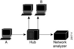
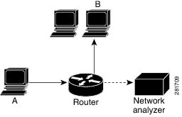
Getting Started with Traffic Mirroring

This chapter introduces traffic mirroring, key concepts, traffic mirroring types, and key terminology. Users can learn about how traffic mirroring works to enable network analysis without impacting live traffic.

Traffic mirroring

Traffic mirroring or port mirroring is a network monitoring feature that

  • monitors Layer 3 network traffic passing in or out of Ethernet interfaces

  • directs this traffic to a network analyzer for analysis, and

  • operates as a proprietary function under Cisco Switched Port Analyzer (SPAN).

Table 1. Feature History Table

Feature Name

Release Information

Feature Description

Traffic Mirroring

Release 25.1.1

Introduced in this release on: Fixed Systems (8010 [ASIC: A100])

Traffic mirroring, also known as port mirroring or Switched Port Analyzer (SPAN), is a proprietary feature by Cisco. It allows the monitoring of Layer 3 network traffic that enters or exits a set of Ethernet interfaces. This mirrored traffic can then be directed to a network analyzer for further analysis.

This feature is now supported on:

  • 8011-4G24Y4H-I

Benefits of traffic mirroring

Traffic mirroring allows you to

  • monitor Layer 3 network traffic

  • analyze traffic using a network analyzer, and

  • mirror traffic without affecting the switching of traffic on source interfaces.

Configuration guidelines for traffic mirroring

These guidelines apply to traffic mirroring:

  • Supports mirroring traffic on a GRE IPv4 or IPv6 tunnel, also known as Encapsulated Remote Switched Port Analyzer (ERSPAN).

  • The system allows eight monitor sessions for ERSPAN, four monitor sessions for local SPAN, and four monitor sessions for SPAN to file.

  • The total number of monitor sessions for all SPAN features is eight.

Restrictions for traffic mirroring

These restrictions apply to traffic mirroring:

  • The router does not support traffic mirroring counters per interface.

  • The router does not support bundle member interfaces as sources for mirroring sessions.

  • The router does not support port-level mirroring for any type of SPAN.

  • ERSPAN tunnel statistics is not supported.

  • The dropped packets at NPU cannot be captured by regular ERSPAN session. For capturing dropped packets at NPU, use the mirror forward-drop packet feature.

  • From Release 24.3.1, layer 2 SPAN features are supported on PWHE. For more information about the layer 2 SPAN features supported on PWHE, see the Traffic Mirroring on PWHE section in the L2VPN Configuration Guide for Cisco 8000 Series Routers.

Traffic mirroring terminology

Understanding traffic mirroring terminology is essential for effective configuration and troubleshooting.

These are the key terms associated with traffic mirroring:

  • Ingress traffic: Traffic that enters the router.

  • Egress traffic: Traffic that leaves the router.

  • Source port: A port that the system monitors using traffic mirroring. It is also known as monitored port.

  • Destination port: A port that monitors the source ports. Usually, a network analyzer is connected here.

  • Monitor session: A collection of traffic mirroring configurations that consists of a single destination and many source interfaces.

Source port

A source port, as used in traffic mirroring, is a switched or routed port that

  • is monitored for network traffic analysis

  • supports monitoring of ingress or Rx traffic in a single local or remote mirroring session, and

  • supports source ports up to 800.

Characteristics of source port

A source port has these characteristics:

  • It supports any port type, such as Bundle Interface, sub-interface, 100-Gigabit Ethernet, and 400-Gigabit Ethernet.

  • It does not support Bridge group virtual interfaces (BVIs).

  • It can only be monitored in one traffic mirroring session at a time.

  • It cannot be a destination port.

  • It can be configured with a direction, ingress for monitoring. The direction applies to all physical ports in a bundle.

Monitor session

In traffic mirroring, a monitor session is a collection of traffic mirroring configurations that

  • consists of a single destination and can have several source interfaces

  • sends traffic from source interfaces or ports to a monitoring or a destination port

  • combines mirrored traffic streams at the destination port when multiple source ports are present, and

  • results in a mixture of traffic from one or more source ports at the destination port.

Characteristics of monitor session

Monitor sessions have these characteristics:

  • Each monitor session can have only one destination port.

  • Each destination port can belong to only one monitor session.

  • The destination of an ERSPAN monitoring session is either a GRE IPv4 or a GRE IPv6 tunnel.

How traffic mirroring works

Traffic mirroring consists of these key operations:

  • copy traffic from Layer 3 interfaces or sub-interfaces.

  • send copied traffic to a destination for analysis.

  • use traffic mirroring ports configured to receive packet copies.

Traffic mirroring functions differently on switches and hubs due to a fundamental difference.

Summary

These are the key components involved in traffic mirroring:

  • Copying traffic: Duplicating network traffic from specified sources.

  • Source of traffic: Traffic is copied from Layer 3 interfaces or sub-interfaces.

  • Destination for analysis: The copied traffic is sent to a designated location . For example, a traffic analyzer for evaluation.

  • Traffic mirroring ports: Specific ports configured to receive these packet copies.

  • Unicast traffic capture: The process enables the capture of unicast traffic, which is particularly important for devices like switches and routers that typically direct unicast packets to specific ports.

Traffic mirroring copies network traffic from Layer 3 interfaces to designated ports for analysis, enabling the capture of unicast traffic. On hubs, all ports receive packet copies, allowing easy traffic capture. In contrast, switches and routers require traffic mirroring to analyze unicast traffic since they direct packets to specific ports based on MAC address learning. Configuring mirroring ports allows analyzers to evaluate network traffic effectively.

These stages describe traffic mirroring:

  • MAC address learning - the switch or router learns the MAC address of Host B.

  • Forwarding decision - the switch or router decides to forward unicast traffic from Host A to Host B based on the learned MAC address.

  • Traffic forwarding - the unicast traffic is forwarded to the specific port associated with Host B.

  • Traffic analyzer visibility - this unicast traffic escapes detection by the traffic analyzer because the traffic directs itself to a specific port and does not broadcast.

Consider this example, where, if you want to capture Ethernet traffic that is sent by host A to host B, and both are connected to a hub, attach a traffic analyzer to the hub. All other ports see the traffic between hosts A and B.

Workflow

Figure 1. Traffic mirroring operation on a hub

Consider this example, where, the traffic analyzer captures only traffic that is flooded to all ports.

Figure 1. Network analysis does not work on a router without traffic mirroring

In this configuration, the traffic analyzer captures only traffic that is flooded to all ports, including:

  • broadcast traffic

  • multicast traffic with CGMP or Internet Group Management Protocol (IGMP) snooping disabled, and

  • unknown unicast traffic on a switch.

An extra feature is necessary that artificially copies unicast packets that host A sends. This extra feature is traffic mirroring. When traffic mirroring is enabled, the traffic analyzer is attached to a port that is configured to receive a copy of every packet that host A sends. This port is called a traffic mirroring port. The other sections of this document describe how you can fine tune the traffic mirroring feature.

When...

Then...

a hub receives a packet on one port

the hub sends out a copy of that packet from all ports except the one where the packet was received.

a switch boots up

the switch begins building a Layer 2 forwarding table based on the source MAC addresses of received packets.

the switch builds its Layer 2 forwarding table

the switch forwards traffic destined for a MAC address directly to the corresponding port.