- SIP Features Roadmap
- Overview of SIP
- Basic SIP Configuration
- Achieving SIP RFC Compliance
- Configuring SIP Call-Transfer Features
- Configuring SIP Message, Timer, and Response Features
- Configuring SIP AAA Features
- Configuring SIP Connection-Oriented Media, Forking, and MLPP Features
- Configuring SIP Bind Features
- Configuring SIP DTMF Features
- Configuring SIP Support for SRTP
- Configuring SIP Support for Hookflash
- Configuring SIP ISDN Support Features
- Transparent Tunneling of QSIG and Q.931 over SIP TDM Gateways and SIP-SIP Cisco Unified Border Elements
- Configuring SIP RSVP Features
- Configuring SIP QoS Features
- Configuring SIP MWI Features
- Verifying and Troubleshooting SIP Features
- Finding Feature Information
- Contents
- Prerequisites for SIP Connection-Oriented Media, Forking, and MLPP
- Restrictions for SIP Connection-Oriented Media, Forking, and MLPP
- Information About SIP Connection-Oriented Media, Forking, and MLPP
Configuring SIP Connection-Oriented Media, Forking, and MLPP Features
This chapter describes how to configure the following media-support features for SIP:
•![]() SIP: Connection-Oriented Media (Comedia) Enhancements for SIP
SIP: Connection-Oriented Media (Comedia) Enhancements for SIP
•![]() SIP: Multilevel Precedence and Priority Support
SIP: Multilevel Precedence and Priority Support
•![]() SIP Support for Media Forking
SIP Support for Media Forking
Feature History for SIP: Connection-Oriented Media (Comedia) Enhancements for SIP
|
|
|
12.2(13)T |
The feature was introduced. |
History for the SIP: Multilevel Precedence and Priority Support Feature
|
|
|
12.4(2)T |
This feature was introduced. |
Feature History for SIP Support for Media Forking
|
|
|
12.2(15)T |
The feature was introduced. |
Finding Feature Information
Use Cisco Feature Navigator to find information about platform support and Cisco IOS and Catalyst OS software image support. To access Cisco Feature Navigator, go to http://www.cisco.com/go/cfn. An account on Cisco.com is not required.
Contents
•![]() Prerequisites for SIP Connection-Oriented Media, Forking, and MLPP
Prerequisites for SIP Connection-Oriented Media, Forking, and MLPP
•![]() Restrictions for SIP Connection-Oriented Media, Forking, and MLPP
Restrictions for SIP Connection-Oriented Media, Forking, and MLPP
•![]() Information About SIP Connection-Oriented Media, Forking, and MLPP
Information About SIP Connection-Oriented Media, Forking, and MLPP
•![]() How to Configure SIP Connection-Oriented Media, Forking, and MLPP Features
How to Configure SIP Connection-Oriented Media, Forking, and MLPP Features
•![]() Configuration Examples for SIP Connection-Oriented Media, Forking, and MLPP Features
Configuration Examples for SIP Connection-Oriented Media, Forking, and MLPP Features
Prerequisites for SIP Connection-Oriented Media, Forking, and MLPP
SIP: Connection-Oriented Media Enhancements for SIP Feature
•![]() Configure NAT. For information about configuring NAT, see Configuring Network Address Translation: Getting Started.
Configure NAT. For information about configuring NAT, see Configuring Network Address Translation: Getting Started.
SIP Support for Media Forking Feature
•![]() Configure the gateway receive-rtcp timer (using the timer receive-rtcp command on the gateway) if a SIP media activity timer is desired. The timer monitors and disconnects calls if no Real-Time Control Protocol (RTCP) packets are received within a configurable time period.
Configure the gateway receive-rtcp timer (using the timer receive-rtcp command on the gateway) if a SIP media activity timer is desired. The timer monitors and disconnects calls if no Real-Time Control Protocol (RTCP) packets are received within a configurable time period.
•![]() If using a Cisco 2600 series, Cisco 3600 series, or Cisco 37xx, ensure that the voice card is configured for high-complexity mode of operation for full media-forking functionality.
If using a Cisco 2600 series, Cisco 3600 series, or Cisco 37xx, ensure that the voice card is configured for high-complexity mode of operation for full media-forking functionality.
•![]() If using a Cisco 7200 series, ensure that the voice card is configured for high-complexity mode of operation.
If using a Cisco 7200 series, ensure that the voice card is configured for high-complexity mode of operation.
•![]() If using a Cisco AS5300, ensure that the proper version of VCWare is loaded onto your router. For media forking, the voice feature card is the DSPM Voice (C542 or C549).
If using a Cisco AS5300, ensure that the proper version of VCWare is loaded onto your router. For media forking, the voice feature card is the DSPM Voice (C542 or C549).
Restrictions for SIP Connection-Oriented Media, Forking, and MLPP
SIP: Connection-Oriented Media Enhancements for SIP Feature
•![]() The feature does not support the a=direction:both attribute of the Session Description Protocol (SDP) message, as defined in the Internet Engineering Task Force (IETF) draft, http://tools.ietf.org/html/draft-ietf-mmusic-sdp-comedia-00
The feature does not support the a=direction:both attribute of the Session Description Protocol (SDP) message, as defined in the Internet Engineering Task Force (IETF) draft, http://tools.ietf.org/html/draft-ietf-mmusic-sdp-comedia-00
•![]() There is likewise no corresponding command-line-interface (CLI) command. If the SIP gateway receives an SDP message specifying a=direction:both, the endpoint is treated by the gateway as active and is considered to be inside the NAT.
There is likewise no corresponding command-line-interface (CLI) command. If the SIP gateway receives an SDP message specifying a=direction:both, the endpoint is treated by the gateway as active and is considered to be inside the NAT.

Note ![]() Proxy parallel forking is not supported with this feature unless all endpoints reply with 180 message response without SDP, because this feature does not handle media coming from multiple endpoints simultaneously.
Proxy parallel forking is not supported with this feature unless all endpoints reply with 180 message response without SDP, because this feature does not handle media coming from multiple endpoints simultaneously.
SIP Support for Media Forking Feature
•![]() The following capabilities are not supported:
The following capabilities are not supported:
–![]() The capability to use IP multicast.
The capability to use IP multicast.
–![]() The capability to create streams with different codecs.
The capability to create streams with different codecs.
–![]() The capability to use media forking functionality over Transmission Control Protocol (TCP). User Datagram Protocol (UDP) only is supported.
The capability to use media forking functionality over Transmission Control Protocol (TCP). User Datagram Protocol (UDP) only is supported.
–![]() The capability to make fax calls when multiple streams are used.
The capability to make fax calls when multiple streams are used.
–![]() The capability to make modem calls when multiple streams ar e used.
The capability to make modem calls when multiple streams ar e used.
–![]() IP-to-IP hairpinning, because there is no telephony call leg to be associated with a call.
IP-to-IP hairpinning, because there is no telephony call leg to be associated with a call.
–![]() When using no voice activity detection (VAD), you can use 10 percent of the capacity of the router to make media forked calls. If no VAD is configured on the Cisco 7200 series, a maximum of 15 channels can be used. For example, on a Cisco 2691, two T1s are supported. Ten percent of two T1s is 4.8 calls, so 4.8 media forking calls can be performed when no VAD is configured. For a Cisco AS5300, four T1s are supported that give a total of 96 calls. Ten percent of 96 is 9.6 calls, so 9.6 media forking calls can be performed when no VAD is configured.
When using no voice activity detection (VAD), you can use 10 percent of the capacity of the router to make media forked calls. If no VAD is configured on the Cisco 7200 series, a maximum of 15 channels can be used. For example, on a Cisco 2691, two T1s are supported. Ten percent of two T1s is 4.8 calls, so 4.8 media forking calls can be performed when no VAD is configured. For a Cisco AS5300, four T1s are supported that give a total of 96 calls. Ten percent of 96 is 9.6 calls, so 9.6 media forking calls can be performed when no VAD is configured.
•![]() The following restrictions apply to codec usage:
The following restrictions apply to codec usage:
–![]() The codecs implemented are G.711, G.729, and G.726 on all supported platforms. No other codecs are supported.
The codecs implemented are G.711, G.729, and G.726 on all supported platforms. No other codecs are supported.
–![]() For dynamic payload type codecs (G.726), the payload type must be the same for all streams in the call. This ensures that the codec is mapped to the same payload type on all streams of a re-Invite message.
For dynamic payload type codecs (G.726), the payload type must be the same for all streams in the call. This ensures that the codec is mapped to the same payload type on all streams of a re-Invite message.
–![]() The codecs on all the streams must be the same and must be one of the supported codecs. If a re-Invite message is received and multiple codecs are listed in the m-lines of the forked-media streams, the gateway attempts to find the codec in the list that matches the first stream. If a matching codec is not found, the stream is rejected by setting the port number to 0 in the response.
The codecs on all the streams must be the same and must be one of the supported codecs. If a re-Invite message is received and multiple codecs are listed in the m-lines of the forked-media streams, the gateway attempts to find the codec in the list that matches the first stream. If a matching codec is not found, the stream is rejected by setting the port number to 0 in the response.
Note ![]() For information on codecs, see the "Map Payload Types to Dynamic Payload Codecs" section.
For information on codecs, see the "Map Payload Types to Dynamic Payload Codecs" section.
•![]() The following restrictions apply to forking functionality and voice feature cards:
The following restrictions apply to forking functionality and voice feature cards:
–![]() With the Cisco 2600 series routers, Cisco 3600 series routers, or Cisco 37xx routers, forking is partially supported for NM-HDV configured for medium- complexity mode of operation. A maximum of two streams is supported, and the only combinations supported are the following: voice-only on both streams and voice plus dual-tone multifrequency (DTMF)-relay on both streams. For full functionality, configure the NM-HDV for high-complexity mode of operation.
With the Cisco 2600 series routers, Cisco 3600 series routers, or Cisco 37xx routers, forking is partially supported for NM-HDV configured for medium- complexity mode of operation. A maximum of two streams is supported, and the only combinations supported are the following: voice-only on both streams and voice plus dual-tone multifrequency (DTMF)-relay on both streams. For full functionality, configure the NM-HDV for high-complexity mode of operation.
–![]() With the Cisco 7200 series routers, the Enhanced High-Capacity Digital Voice port adapter (PA-VXC-2TE1+ T1/E1) must be configured for high-complexity mode of operation.
With the Cisco 7200 series routers, the Enhanced High-Capacity Digital Voice port adapter (PA-VXC-2TE1+ T1/E1) must be configured for high-complexity mode of operation.
–![]() With the Cisco AS5300 universal access server, DSPM Voice (C542 and C549) must be configured.
With the Cisco AS5300 universal access server, DSPM Voice (C542 and C549) must be configured.
•![]() The following restrictions apply to DTMF relay:
The following restrictions apply to DTMF relay:
–![]() DTMF-relay is supported as described in RFC 2833, RTP Payload for DTMF Digits, Telephony Tones and Telephony Signals. Cisco proprietary DTMF is not supported.
DTMF-relay is supported as described in RFC 2833, RTP Payload for DTMF Digits, Telephony Tones and Telephony Signals. Cisco proprietary DTMF is not supported.
–![]() When DTMF-relay is configured, only the Real-Time Transport Protocol Named Telephony Event (RTP-NTE) payload format can be used in a forked call. RTP-NTE is described in RFC 2833 and prevents the generation of spurious digits at the receiving gateway.
When DTMF-relay is configured, only the Real-Time Transport Protocol Named Telephony Event (RTP-NTE) payload format can be used in a forked call. RTP-NTE is described in RFC 2833 and prevents the generation of spurious digits at the receiving gateway.
–![]() Streams that include only DTMF-relay packets can be used only in a two-stream call and must be established as the second stream.
Streams that include only DTMF-relay packets can be used only in a two-stream call and must be established as the second stream.
–![]() All forked voice-only and voice plus DTMF-relay streams must use the same codec.
All forked voice-only and voice plus DTMF-relay streams must use the same codec.
•![]() The following restrictions apply to media streams:
The following restrictions apply to media streams:
–![]() Multiple Domain Name System (DNS) media queries are not supported on all media streams. DNS query is done on the fully qualified domain name (FDQN) of the initial stream only.
Multiple Domain Name System (DNS) media queries are not supported on all media streams. DNS query is done on the fully qualified domain name (FDQN) of the initial stream only.
–![]() Media streams are created and deleted only through re-Invite messages. They are not created through the CLI.
Media streams are created and deleted only through re-Invite messages. They are not created through the CLI.
–![]() A maximum of three VoIP media streams are supported because three streams can be concurrently sent to the digital signal processor (DSP).
A maximum of three VoIP media streams are supported because three streams can be concurrently sent to the digital signal processor (DSP).
–![]() Calls that have a single stream (that is, a conventional two-party call) cannot be set up as DTMF only.
Calls that have a single stream (that is, a conventional two-party call) cannot be set up as DTMF only.
–![]() The first stream cannot be deleted while other streams are active, nor can it be put on hold.
The first stream cannot be deleted while other streams are active, nor can it be put on hold.
–![]() The stream type of an active stream cannot be modified. For example, you cannot change a voice-only stream to voice plus DTMF only.
The stream type of an active stream cannot be modified. For example, you cannot change a voice-only stream to voice plus DTMF only.
Information About SIP Connection-Oriented Media, Forking, and MLPP
To configure connection-oriented media and forking features for SIP, you should understand the following concepts:
•![]() SIP: Connection-Oriented Media Enhancements for SIP
SIP: Connection-Oriented Media Enhancements for SIP
•![]() SIP: Multilevel Precedence and Priority Support
SIP: Multilevel Precedence and Priority Support
•![]() SIP Support for Media Forking
SIP Support for Media Forking
SIP: Connection-Oriented Media Enhancements for SIP
The SIP: Connection-Oriented Media (Comedia) Enhancements for SIP feature allows a Cisco gateway to check the media source of incoming Realtime Transport Protocol (RTP) packets, and allows the endpoint to advertise its presence inside or outside of Network Address Translation (NAT). Using the feature enables symmetric NAT traversal by supporting the capability to modify and update an existing RTP session remote address and port.
Feature benefits include the following:
•![]() Ability to check the media source address and port of incoming RTP packets, thereby enabling the remote address and port of the existing session to be updated
Ability to check the media source address and port of incoming RTP packets, thereby enabling the remote address and port of the existing session to be updated
•![]() Enhanced interoperability in networks where NAT devices are unaware of SIP or SDP signaling
Enhanced interoperability in networks where NAT devices are unaware of SIP or SDP signaling
•![]() Ability to advertise endpoint presence inside or outside NAT
Ability to advertise endpoint presence inside or outside NAT
•![]() Ability to specify the connection role of the endpoint
Ability to specify the connection role of the endpoint
To configure the Connection-Oriented Media Enhancements for SIP feature, you should understand the following concepts:
Symmetric NAT Traversal
The Connection-Oriented Media (Comedia) Enhancements for SIP feature provides the following feature to symmetric NAT traversal:
•![]() Allows the Cisco gateway to check the media source of incoming (RTP) packets.
Allows the Cisco gateway to check the media source of incoming (RTP) packets.
•![]() Allows the endpoint to advertise its presence inside or outside of NAT.
Allows the endpoint to advertise its presence inside or outside of NAT.
NAT, which maps the source IP address of a packet from one IP address to a different IP address, has varying functionality and configurations. NAT can help conserve IP version 4 (IPv4) addresses, or it can be used for security purposes to hide the IP address and LAN structure behind the NAT. VoIP endpoints may both be outside NAT, both inside, or one inside and the other outside.
In symmetric NAT, all requests from an internal IP address and port to a specific destination IP address and port are mapped to the same external IP address and port. The feature provides additional capabilities for symmetric NAT traversal.
Prior to the implementation of connection-oriented media enhancements, NAT traversal presented challenges for both SIP, which signals the protocol messages that set up a call, and for RTP, the media stream that transports the audio portion of a VoIP call. An endpoint with connections to clients behind NATs and on the open Internet had no way of knowing when to trust the addressing information it received in the SDP portion of SIP messages, or whether to wait until it received a packet directly from the client before opening a channel back to the source IP:port of that packet. Once a VoIP session was established, the endpoint was, in some scenarios, sending packets to an unreachable address. This scenario typically occurred in NAT networks that were SIP-unaware.
In addition to the challenges posed by NAT traversal in SIP, NAT traversal in RTP requires that a client must know what type of NAT it sits behind, and that it must also obtain the public address for an RTP stream. Any RTP connection between endpoints outside and inside NAT must be established as a point-to-point connection. The external endpoint must wait until it receives a packet from the client so that it knows where to reply. The connection-oriented protocol used to describe this type of session is known as Connection-Oriented Media (Comedia), as defined in the IETF draft, draft-ietf-mmusic-sdp-comedia-04.txt, Connection-Oriented Media Transport in SDP.
Cisco IOS VoiceXML features implement one of many possible SIP solutions to address problems with different NAT types and traversals. With Cisco IOS VoiceXM, the gateway can open an RTP session with the remote end and then update or modify the existing RTP session remote address and port (raddr:rport) with the source address and port of the actual media packet received after passing through NAT. The feature allows you to configure the gateway to modify the RTP session remote address and port by implementing support for the SDP direction (a=direction:<role>) attribute defined in, draft-ietf-mmusic-sdp-comedia-04.txt, Connection-Oriented Media Transport in SDP. Valid values for the attribute are as follows:
•![]() active—the endpoint initiates a connection to the port number on the m= line of the session description from the other endpoint.
active—the endpoint initiates a connection to the port number on the m= line of the session description from the other endpoint.
•![]() passive—the endpoint accepts a connection to the port number on the m= line of the session description sent from itself to the other endpoint.
passive—the endpoint accepts a connection to the port number on the m= line of the session description sent from itself to the other endpoint.
•![]() both—the endpoint both accepts an incoming connection and initiates an outgoing connection to the port number on the m= line of the session description from the other endpoint.
both—the endpoint both accepts an incoming connection and initiates an outgoing connection to the port number on the m= line of the session description from the other endpoint.
The feature introduces CLI commands to configure the following SIP user-agent settings for symmetric NAT:
•![]() The nat symmetric check-media-src command enables checking the incoming packet for media source address. This capability allows the gateway to check the source address and update the media session with the remote media address and port.
The nat symmetric check-media-src command enables checking the incoming packet for media source address. This capability allows the gateway to check the source address and update the media session with the remote media address and port.
•![]() The nat symmetric role command specifies the function of the endpoint in the connection setup procedure. Set the role keyword to one of the following:
The nat symmetric role command specifies the function of the endpoint in the connection setup procedure. Set the role keyword to one of the following:
–![]() active—The endpoint initiates a connection to the port number on the m= line of the session description from the other endpoint.
active—The endpoint initiates a connection to the port number on the m= line of the session description from the other endpoint.
–![]() passive—The endpoint accepts a connection to the port number on the m= line of the session description sent from itself to the other endpoint.
passive—The endpoint accepts a connection to the port number on the m= line of the session description sent from itself to the other endpoint.
Note ![]() The Cisco Comedia implementation does not support a=direction:both. If the Cisco gateway receives a=direction:both in the SDP message, the endpoint is considered active.
The Cisco Comedia implementation does not support a=direction:both. If the Cisco gateway receives a=direction:both in the SDP message, the endpoint is considered active.
Sample SDP Message
v=o
o=CiscoSystemsSIP-GW-UserAgent 5732 7442 IN IP4 10.15.66.43
s=SIP Call
c=IN IP4 10.15.66.43
t=0 0
m=audio 17306 RTP/AVP 0 100
a=rtpmap:0 PCMU/8000
a=rtpmap:100 X-NSE/8000
a=fmtp:100 192-194
a=ptime:20
a=direction:passive
Symmetric NAT Call Flows
The following call flow diagrams describe call setup during symmetric NAT traversal scenarios. Figure 66 shows a NAT device that is unaware of SIP or SDP signaling. The SIP endpoints are not communicating the connection-oriented media direction role in the SDP message. The originating gateway is configured, using the nat symmetric check-media-src command to detect the media source and update the VoIP RTP session to the network address translated address:port pair.
Figure 66 SIP Endpoints Not Communicating the SDP direction:<role> Attribute
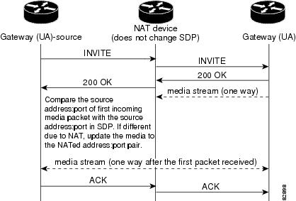
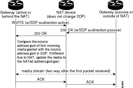
Figure 67 shows a NAT device that is unaware of SIP or SDP signaling, but the SIP endpoints are communicating the connection-oriented media direction role in the SDP message. The originating gateway is configured as a passive entity in the network using the nat symmetric role command. When the passive entity receives a direction role of active, it updates the VoIP RTP session to the network address translated address:port pair.
Figure 67 SIP Endpoints Communicating the SDP direction:<role>
Note ![]() Configuring the originating gateway for passive or active setting can differ from the NAT device setup. The SIP user agent communicates the CLI configured direction role in the SDP body. Checking for media packets is automatically enabled only if the gateway receives a direction role of active or both.
Configuring the originating gateway for passive or active setting can differ from the NAT device setup. The SIP user agent communicates the CLI configured direction role in the SDP body. Checking for media packets is automatically enabled only if the gateway receives a direction role of active or both.
When renegotiating media mid call, such as when the call is moving from standard to T38 fax relay, the UDP ports used are often renegotiated on third-party endpoints. This new port is not recognized by the symmetric NAT feature.
SIP: Multilevel Precedence and Priority Support
The SIP: Multilevel Precedence and Priority Support feature enables Cisco IOS gateways to interoperate with other multilevel-precedence and preemption (MLPP)-capable circuit-switched networks.
An MLPP-enabled call has an associated priority level that applications that handle emergencies and congestions use to determine which lower-priority call to preempt in order to dedicate their end-system resources to high-priority communications. This feature addresses the aspect of preemption when interworking with defense-switched networks (DSNs) that are connected through the Cisco IOS gateway.
To configure the feature, it is helpful to understand the following concepts:
•![]() Precedence and Service Domains for the SIP
Precedence and Service Domains for the SIP
•![]() Network Solution and System Flows for the SIP
Network Solution and System Flows for the SIP
Description of the SIP
The SIP: Multilevel Precedence and Priority Support feature enables Cisco IOS gateways to interoperate with other MLPP-capable circuit-switched networks. The U.S. Department of Defense (DoD) and Defense Information Service Agency (DISA) mandate that all VoIP network elements support this capability.
MLPP is a service that allows properly validated users to preempt lower-priority phone calls either to targeted stations or through fully subscribed shared resources such as time-division multiplexing (TDM) trunks or conference bridges. With this capability, high-ranking personnel are ensured communication to critical organizations and personnel during a national emergency.
Connections and resources that belong to a call from an MLPP subscriber are marked with a precedence level and domain identifier and are preempted only by calls of higher precedence from MLPP users in the same domain. The DSN switch sets the maximum precedence level for a subscriber statically. When that subscriber originates a call, it is tagged with that precedence level (if none is provided) or with one that the user provides.
Cisco IOS gateways act as transit trunking network elements to map incoming precedence levels to outgoing signaling. This does not provide any schemes to configure the maximum levels for the subscriber lines, or interpret the levels based on the prefixes when a call is offered through a channel-associated signaling/R2 (CAS/R2) type of interface.
Precedence and Service Domains for the SIP
Precedence provides for preferred handling of call-service requests. It involves assigning and validating priority levels to calls and prioritized treatment of MLPP service requests. The nature of precedence assignment is based on an internal decision, in that the user chooses to apply or not to apply assigned precedence level to a call. MLPP precedence is unrelated to other call admission control (CAC) or enhanced emergency services (E911) services. User invocation of an MLPP request is provided through dedicated dial access codes and selectors in the dial string. In particular, a precedence call is requested by the user using the string prefix NP, where P is the requested precedence level and N is the preconfigured MLPP access digit.
The range of precedence values in DSN/Public SS7 Network Format (DSN/Q.735) service domains is shown in Table 37.
|
|
|
|---|---|
0 |
FLASH OVERRIDE |
1 |
FLASH |
2 |
IMMEDIATE |
3 |
PRIORITY |
4 |
ROUTINE |
The Defense Red Switched Network (DRSN) service domain has six levels of precedence as shown in Table 38.
|
|
|
|---|---|
0 |
FLASH OVERRIDE OVERRIDE |
1 |
FLASH OVERRIDE |
2 |
FLASH |
3 |
IMMEDIATE |
4 |
PRIORITY |
5 |
ROUTINE |
A subscriber A (0100) calling B (0150) that wants to explicitly associate a precedence level (priority) to a particular call, would dial the following digits:
8555-3-0150
^ ^ ^
| | |___________ Called number
| |_____________ Call precedence—priority
|__________________ MLPP service prefix
If subscriber A is an ordinary customer with an assigned precedence level of 4 (routine), then MLPP automatically treats this call as a routine call.
In SIP and ISDN signaling, however, the precedence levels and domain-name space information are carried discretely in the protocol messages and do not require appropriate prefixes to the dialed digits.
Precedence-Level Support in SIP Signaling
MLPP information in a SIP signal is carried in the Resource-Priority header. The header field marks a SIP request as desiring prioritized resource access depending on the precedence level invoked or assigned to the call originator. The syntax for the Resource-Priority header field is as follows:
Resource-Priority="Resource-Priority" HCOLON Resource-value * (COMMA Resource-value)
Resource-value=namespace "." r-priority
namespace=*(alphanum / "-")
r-priority=*(alphanum / "-")
Three name spaces are defined by the draft to cater to different service domains:
•![]() dsn—Adopted by U.S. Defense Switched Network and DISA. It defines five precedence values: routine, priority, immediate, flash, flash-override.
dsn—Adopted by U.S. Defense Switched Network and DISA. It defines five precedence values: routine, priority, immediate, flash, flash-override.
•![]() q735—Used by Signaling System 7 (SS7) networks based on ITU Q.735.3. It also defines five precedence values: 4, 3, 2, 1, 0.
q735—Used by Signaling System 7 (SS7) networks based on ITU Q.735.3. It also defines five precedence values: 4, 3, 2, 1, 0.
•![]() drsn—Used in U.S. DRSN. It defines six precedence values: routine, priority, immediate, flash, flash-override, flash-override-override.
drsn—Used in U.S. DRSN. It defines six precedence values: routine, priority, immediate, flash, flash-override, flash-override-override.
The Cisco IOS gateway supports all three name spaces. In order to facilitate interworking with those network elements that support any one type of name space, the name space is configurable.
Precedence-Level Support in ISDN Signaling
MLPP service is provided by the user using the precedence information element (IE) 41 to carry the precedence levels MLPP service domain in the SETUP message. The standard specifies five level values represented by four bits and only one domain indicator value (0000000—dsn).
Mapping of DRSN name space values into ISDN poses a problem because the standard does not provide a unique value for flash-override-override. The flash-override-override value is represented as 1000 (8). When you use the most significant bit of the four-bit representation, this information is conveyed to other implementations that interpret or support flash-override-override and also ensure that the call is still treated as the highest priority with those implementations that do not use the most significant bit (MSB).
Preemption for the SIP
Preemption is the termination of existing calls of lower precedence and extension of a call of higher precedence to or through a target device. Precedence includes notification and acknowledgment of preempted users and reservation of any shared resources immediately after preemption and before preempted call termination.
Preemption takes one of two forms:
•![]() The called party may be busy with a lower precedence call, which must be preempted in favor of completing higher precedence call from the calling party.
The called party may be busy with a lower precedence call, which must be preempted in favor of completing higher precedence call from the calling party.
•![]() Network resources may be busy with calls, some of which are of lower precedence than the calls requested by the calling party. One or more of these lower-precedence calls is preempted to complete the higher-precedence call.
Network resources may be busy with calls, some of which are of lower precedence than the calls requested by the calling party. One or more of these lower-precedence calls is preempted to complete the higher-precedence call.
Cisco IOS gateways do not implement any type of preemption service logic; that task wholly rests with the DSN switch.
Network Solution and System Flows for the SIP
Figure 68 shows the system flow for a typical user scenario.
The request from a higher priority interrupts a lower-priority usage at a user terminal, such as an IP phone.
The Primary Rate Interface (PRI) is connected to a DSN WAN through a Cisco IOS gateway. For the purpose of this illustration, we assume that users A, B, C, and D are properly configured in the DSN switch with the appropriate maximum priority levels, as follows:
•![]() User A—Priority FLASH
User A—Priority FLASH
•![]() User B—Priority IMMEDIATE
User B—Priority IMMEDIATE
•![]() User C—Priority ROUTINE
User C—Priority ROUTINE
•![]() User D—Priority FLASH
User D—Priority FLASH
User C establishes a call with User A. User C wants the call to be set to the maximum priority value and so dials the appropriate code. User D tries to call a security advisor. Because User D's call has the highest priority, Figure 68 provides an overall illustration on how MLPP works in this scenario and the part this new functionality on the Cisco IOS gateway plays in achieving MLPP.
Note ![]() The MLPP application is an existing feature and is leveraged while interworking with Cisco IOS gateways through SIP.
The MLPP application is an existing feature and is leveraged while interworking with Cisco IOS gateways through SIP.
Figure 68 Network Solution and System Flow
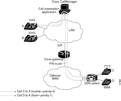
A typical network solution and call flow is as follows (see Figure 68):
•![]() User C (7777) calls User A (1000) and they are in a routine call.
User C (7777) calls User A (1000) and they are in a routine call.
•![]() User D (8888) wants to call User A (1000). User D (8888) goes off-hook and dials 1000.
User D (8888) wants to call User A (1000). User D (8888) goes off-hook and dials 1000.
•![]() The DSN switch interprets the call priority by looking at the dialed digits and maps to the ISDN SETUP message:
The DSN switch interprets the call priority by looking at the dialed digits and maps to the ISDN SETUP message:
Precedence IE: Level - 0000, Service Domain - 0000000
The call is routed through the Cisco IOS gateway.
•![]() The Cisco IOS gateway passes the incoming call with the dialed digits. It maps the incoming ISDN Precedence IE to the Resource-Priority header values. The management system applies the local policy (as configured on the gateway) to choose the name space where it wants to represent the levels:
The Cisco IOS gateway passes the incoming call with the dialed digits. It maps the incoming ISDN Precedence IE to the Resource-Priority header values. The management system applies the local policy (as configured on the gateway) to choose the name space where it wants to represent the levels:
INVITE Resource-Priority: dsn.flash
The management system validates the dialed number (DN) and identifies that User A (1000) is already in a call.
•![]() The management system looks at the precedence level of the call from User D (8888) (FLASH) and compares this with the precedence of the existing call between User A (1000) and User C (7777) (ROUTINE).
The management system looks at the precedence level of the call from User D (8888) (FLASH) and compares this with the precedence of the existing call between User A (1000) and User C (7777) (ROUTINE).
•![]() The management system decides to preempt the User C (7777) to User A (1000) call.
The management system decides to preempt the User C (7777) to User A (1000) call.
There are two options for the management system to provide the treatment to User C (7777). It either provides the preemption tone from its end if it was transcoding and Real-Time Transport Protocol (RTP) streams were controlled by it. Or if the RTP streams were directly established between the endpoints gateway and the phone, it inserts a suitable cause value in the SIP Reason header and lets the gateway or the DSN switch provide the treatment. The management system presents the cause value either in new Reason header name space preemption or in Q.850 format:
BYE Reason: Preemption; cause=1;text="UA_Preemption"
•![]() The application marks the endpoint User A available for reuse and offers User D's call to it.
The application marks the endpoint User A available for reuse and offers User D's call to it.
•![]() If User D (8888) disconnects the call, the management system clears the resources and preserves the existing call between User A (1000) and User C (7777).
If User D (8888) disconnects the call, the management system clears the resources and preserves the existing call between User A (1000) and User C (7777).
If a higher precedence call comes in during the User D (8888) to User A (1000) call, the management system processes the higher-order preemption. For the IP phones, when a user's profile is assigned to the phone, calls initiated from the phone inherit the precedence of the assigned user.
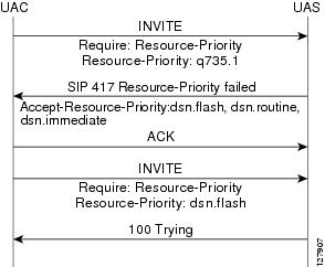
Figure 69 and Figure 70 show examples of a Resource-Priority (R-P) header call flows with loose mode and strict mode selected.
Note ![]() In the loose mode, unknown values of name space or priority values received in the Resource-Priority header in SIP requests are ignored by the gateway. The request is processed as if the Resource-Priority header were not present.
In the loose mode, unknown values of name space or priority values received in the Resource-Priority header in SIP requests are ignored by the gateway. The request is processed as if the Resource-Priority header were not present.
Figure 69 R-P Header Origination with Loose Mode Selected
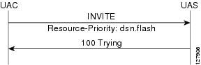
Figure 70 R-P Header Origination with Strict Mode Selected
SIP Support for Media Forking
The SIP Support for Media Forking feature provides the ability to create midcall multiple streams (or branches) of audio associated with a single call and then send those streams of data to different destinations. The feature allows service providers to use technologies such as speech recognition, voice authentication, and text-to-speech conversion to provide sophisticated services to their end-user customers. An example is a web-browsing application that uses voice recognition and text-to-speech (TTS) technology to make reservations, verify shipments, or order products.
Feature benefit is as follows: SIP media streams are created and deleted only through re-Invite messages; no CLI is required.
To configure the SIP Support for Media Forking feature, you should understand the following concepts:
•![]() Multiple Codec Selection Order and Dynamic Payload Codecs
Multiple Codec Selection Order and Dynamic Payload Codecs
Media Streams
With the SIP Support for Media Forking feature, you can create up to three Real-Time Transport Protocol (RTP) media streams to and from a single DS0 channel. In addition, separate gateway destinations (IP address or UDP port) are maintained for each of the streams. The streams are bidirectional; media received from the destination gateways are mixed in the DSP before being sent to the DS0 channel, and pulse code modulation (PCM) received from the DS0 is duplicated and sent to the destination gateways.
Originating gateways establish multiple media streams on the basis of Session Description Protocol (SDP) information included in midcall re-Invites received from a destination gateway, third-party call controller, or other SIP signaling entity. Only one SIP call leg is involved in media forking at the gateway, so the SIP signaling entity that initiates the re-Invites must be capable of aggregating the media information for multiple destinations (such as IP address, port number, payload types, or codecs) into one SDP description. Multiple m-lines in the SDP are used to indicate media forking, with each m-line representing one media destination.
Note ![]() SIP media streams are created and deleted only through re-Invite messages; no specific CLI is required.
SIP media streams are created and deleted only through re-Invite messages; no specific CLI is required.
The ability to create midcall multiple streams (or branches) of audio associated with a single call and send those streams of data to different destinations is similar to a three-way or conference call. A media-forked call has some differences. For example, in a three-way call, each party hears all of the other parties. But in a media-forked call, only the originating caller (the controller) hears the audio (voice and DTMF digits) from all the other participants. The other participants hear audio only from the originating caller and not from each other.
Another difference between a three-way call and a media-forked call is that media streams can be configured on the gateway. Three-way calls send the audio to all of the other parties involved in the call. However, media-forking permits each media stream to be independently configured. For example, one media stream to one party may include both voice and DTMF digits, whereas another media stream to another party may include only DTMF digits.
The feature supports three types of media streams: voice, DTMF-relay only, and voice plus DTMF-relay.
Note ![]() In addition to the following discussion, see the following as appropriate:
In addition to the following discussion, see the following as appropriate:
•![]() For information on codecs, see the "Map Payload Types to Dynamic Payload Codecs" section.
For information on codecs, see the "Map Payload Types to Dynamic Payload Codecs" section.
•![]() For information on payload types see the "Multiple Codec Selection Order and Dynamic Payload Codecs" section.
For information on payload types see the "Multiple Codec Selection Order and Dynamic Payload Codecs" section.
•![]() For information on DTMF relay, see the "SIP INFO Method for DTMF Tone Generation" section of the Configuring SIP DTMF Features chapter.
For information on DTMF relay, see the "SIP INFO Method for DTMF Tone Generation" section of the Configuring SIP DTMF Features chapter.
Voice Media Streams
Voice-only media streams send all audio from the DS0 channel, and the audio is encoded according to the selected codec. Voice-only media streams have the following characteristics:
•![]() DTMF digits are sent as in-band audio.
DTMF digits are sent as in-band audio.
•![]() All forked streams must use the same codec, which is referred to as simple forking.
All forked streams must use the same codec, which is referred to as simple forking.
•![]() Only the following codecs and their variants are allowed: G.711, G.726, and G.729.
Only the following codecs and their variants are allowed: G.711, G.726, and G.729.
•![]() For the G.726 codecs, dynamic payload types are negotiated in SDP. SDP messages contain capabilities information that is exchanged between gateways. The payload types must be the same for all streams in the call.
For the G.726 codecs, dynamic payload types are negotiated in SDP. SDP messages contain capabilities information that is exchanged between gateways. The payload types must be the same for all streams in the call.
DTMF-Relay Media Streams
DTMF relay provides reliable digit relay between VoIP gateways and a standardized means of transporting DTMF tones in RTP packets. DTMF-relay media streams have the following characteristics:
•![]() DTMF-relay media streams do not include voice and do not use a codec. DTMF-relay packets are sent when the originating party presses a DTMF digit.
DTMF-relay media streams do not include voice and do not use a codec. DTMF-relay packets are sent when the originating party presses a DTMF digit.
•![]() Only RTP-NTE can be used in a forked DTMF-relay call. RTP-NTE is used to transport DTMF digits and other telephony events between two endpoints. RTP-NTE prevents the generation of spurious digits at the receiving gateway and is further described in RFC 2833.
Only RTP-NTE can be used in a forked DTMF-relay call. RTP-NTE is used to transport DTMF digits and other telephony events between two endpoints. RTP-NTE prevents the generation of spurious digits at the receiving gateway and is further described in RFC 2833.
•![]() DTMF-relay streams are supported only on calls with two established streams and can appear only as the second stream.
DTMF-relay streams are supported only on calls with two established streams and can appear only as the second stream.
•![]() The payload-type value assigned to DTMF-relay packets in SDP must be the same for all streams that use DTMF-relay. The default payload type for Cisco gateways is 101.
The payload-type value assigned to DTMF-relay packets in SDP must be the same for all streams that use DTMF-relay. The default payload type for Cisco gateways is 101.
Voice Plus DTMF-Relay Media Streams
Voice plus DTMF-relay media streams send both encoded voice and DTMF-relay packets and have the following characteristics:
•![]() The receiving gateway can distinguish the voice component from the DTMF component.
The receiving gateway can distinguish the voice component from the DTMF component.
•![]() Unlike DTMF-relay, voice plus DTMF is supported on any of the established streams of a forked call.
Unlike DTMF-relay, voice plus DTMF is supported on any of the established streams of a forked call.
•![]() Only RTP-NTE can be used in a forked DTMF-relay call.
Only RTP-NTE can be used in a forked DTMF-relay call.
•![]() All streams must use the same codec (simple forking).
All streams must use the same codec (simple forking).
•![]() Only the following codecs and their variants are allowed: G.711, G.726, and G.729.
Only the following codecs and their variants are allowed: G.711, G.726, and G.729.
•![]() For the G.726 codecs, dynamic payload types are negotiated in SDP. SDP messages contain capabilities information that are exchanged between gateways. The payload types must be the same for all streams in the call.
For the G.726 codecs, dynamic payload types are negotiated in SDP. SDP messages contain capabilities information that are exchanged between gateways. The payload types must be the same for all streams in the call.
•![]() The payload-type value assigned to DTMF-relay packets in SDP must be the same for all streams that use DTMF-relay. The default payload type for Cisco gateways is 101.
The payload-type value assigned to DTMF-relay packets in SDP must be the same for all streams that use DTMF-relay. The default payload type for Cisco gateways is 101.
Multiple Codec Selection Order and Dynamic Payload Codecs
When using multiple codecs you must create a voice class in which you define a selection order for codecs, and you can then apply the voice class to VoIP dial peers. The voice class codec command in global configuration mode allows you to define the voice class that contains the codec selection order. Then you use the voice-class codec command in dial-peer configuration mode to apply the class to individual dial peers.
If there are any codecs that use dynamic payload types (g726r16, g726r24), Cisco IOS software assigns the payload types to these codecs in the order in which they appear in the configuration, starting with the first available payload type in the dynamic range. The range for dynamic payload types is from 96 to 127, but Cisco IOS software preassigns the following payload types by default.
|
|
|
|---|---|
96 |
fax |
97 |
fax-ack |
100 |
NSE |
101 |
NTE |
121 |
DTMF-relay |
122 |
Fax-relay |
123 |
CAS |
125 |
ClearChan |
Because the payload types have been reserved by the default assignments shown in the table, Cisco IOS software automatically assigns 98 to the first dynamic codec in the dial-peer configuration, 99 to the second, and 102 to the third.
Some of these preassigned payload types can be changed with the modem relay command. This command allows changes to the available payload types that can be used for codecs.
For outgoing calls on the originating gateway, all of the codecs that are configured in the codec list used by the dial peer are included in the SDP of the Invite message.
On the terminating gateway, Cisco IOS software always uses the dynamic payload types that the originating gateway specified in the SDP of the Invite message. This practice avoids the problem of misaligned payload types for most call types. The exception is when a delayed-media Invite message is received. A delayed-media Invite can be used by a voice portal to signal a terminating gateway before re-Inviting a forking gateway. If a delayed-media Invite is used, the Invite message does not contain SDP information, and the terminating gateway must advertise its own codecs and payload types. It does this in the SDP of its response message (either a 183 or a 200 OK). The terminating gateway assigns payload types to dynamic codecs using the same rules as the originating gateway. However, if there is a difference in either the preassigned dynamic payload types or the order in which the dynamic codecs are listed in the codec list used by the dial peer, the payload types may not be assigned consistently on the originating and terminating gateways. If the terminating gateway selects a different payload type for a dynamic codec, the call may fail.
If a G.726 codec is assigned in the first active stream of the call, there are some scenarios in which the voice portal sends a delayed-media re-Invite message to the second or third terminating gateway. Then, it is necessary to ensure that the originating gateway and the second and third terminating gateways have the same preassigned payload types and the same order of dynamic codecs in the codec list for the dial peer being used for the call. Otherwise, the added media stream may be rejected by the originating gateway if the payload types do not match.
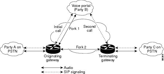
Media Forking Applications
A web-browsing application that uses voice recognition and text-to-speech (TTS) technology to make reservations, verify shipments, or order products is a typical application of media forking. In Figure 71, a client (Party A) uses a telephone to browse the web. Party A calls the voice portal (Party B), and the call is routed through the originating gateway. The voice portal operates like a standard voice gateway and terminates calls to a voice response system that has voice recognition and TTS capabilities. This voice response system takes input from Party A by DTMF digits or voice recognition and returns responses (for example, stock quotes retrieved from the web) to Party A.
The voice portal, or Party B, is also capable of third-party call control (3pcc) and can set up a call between Party A and a third participant (Party C) without requiring direct signaling between Party A and Party C. One example of a possible call between Party A and Party C is if Party A found a restaurant listing while browsing the web and wanted to speak directly to the restaurant to make reservations.
Another feature of the voice portal is that once the call between parties A and C is established, the voice portal can continue to monitor the audio from Party A. By doing so, the voice portal can terminate the connection between Party A and Party C when a preestablished DTMF digit or voice command is received. Party B retains the connection between itself and Party A, in case Party A has any further requests. Continuing with the restaurant example, the continuous connection is important if Party A decides to query yet another restaurant. Party A simply goes back to the connection with Party B, who sets up a call with the new restaurant.
Figure 71 Media Forking Application
Another important aspect of media forking is that although there can be more than one media destination, there is only one signaling destination (in this case, the voice portal). The call leg that was originally set up (from the originating gateway to the voice portal) is maintained for the life of the session. The media destinations are independent of the signaling destination, so media streams (or new destinations) can be added and removed dynamically through re-Invite messages. Media streams are created and deleted only through re-Invite messages rather than through any CLIs.
If you configure the timer receive-rtcp command for a gateway, a Session Initiation Protocol (SIP) media inactivity timer is started for each active media stream. The timer monitors and disconnects calls if no RTCP packets are received within a configurable time period. If any of the timers expire, the entire call is terminated—not just the stream on which the timer expired. If a stream is put on call hold, the timer for that stream is stopped. When the stream is taken off hold, the timer for that stream is started again.
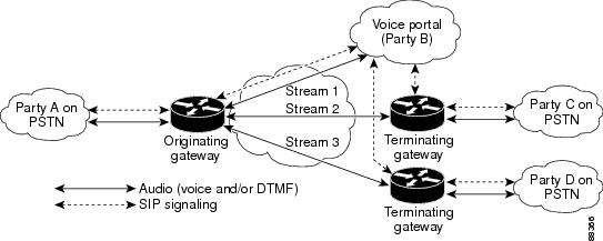
There is a maximum of three VoIP media streams that can be established per call. Figure 72 shows the maximum number of streams.
Figure 72 Multiple Streams
Media Forking Initiation
Media forking is initiated by specifying multiple media fields (m-lines) in the SDP of a re-Invite message. The rules for adding and deleting multiple m-lines conform to RFC 2543, SIP: Session Initiation Protocol Appendix B.
Multiple streams are not created through CLIs.
How to Configure SIP Connection-Oriented Media, Forking, and MLPP Features
This section contains the following procedures:
•![]() Configuring SIP: Connection-Oriented Media Enhancements for SIP
Configuring SIP: Connection-Oriented Media Enhancements for SIP
•![]() Configuring SIP: Multilevel Precedence and Priority Support
Configuring SIP: Multilevel Precedence and Priority Support
•![]() Configuring SIP Support for Media Forking
Configuring SIP Support for Media Forking
•![]() Verifying Connection-Oriented Media and Forking Features for SIP
Verifying Connection-Oriented Media and Forking Features for SIP
Note![]() •
•![]() Before you perform a procedure, familiarize yourself with the following information:
Before you perform a procedure, familiarize yourself with the following information:
–![]() "Prerequisites for SIP Connection-Oriented Media, Forking, and MLPP" section
"Prerequisites for SIP Connection-Oriented Media, Forking, and MLPP" section
–![]() "Restrictions for SIP Connection-Oriented Media, Forking, and MLPP" section
"Restrictions for SIP Connection-Oriented Media, Forking, and MLPP" section
•![]() For help with a procedure, see the troubleshooting section listed above.
For help with a procedure, see the troubleshooting section listed above.
Configuring SIP: Connection-Oriented Media Enhancements for SIP
To configure connection-oriented media enhancements for SIP, perform the following steps.
Note ![]() The following steps enable the gateway to check the media source address and port of the first incoming RTP packet, and optionally to specify whether the endpoint is active or passive. Once the media source check is enabled, the gateway modifies or updates the established VoIP RTP session with upstream addressing information extracted from the SDP body of the received request.
The following steps enable the gateway to check the media source address and port of the first incoming RTP packet, and optionally to specify whether the endpoint is active or passive. Once the media source check is enabled, the gateway modifies or updates the established VoIP RTP session with upstream addressing information extracted from the SDP body of the received request.
SUMMARY STEPS
1. ![]() enable
enable
2. ![]() configure terminal
configure terminal
3. ![]() sip-ua
sip-ua
4. ![]() nat symmetric check-media-source
nat symmetric check-media-source
5. ![]() nat symmetric role {active | passive}
nat symmetric role {active | passive}
6. ![]() exit
exit
DETAILED STEPS
Configuring SIP: Multilevel Precedence and Priority Support
To configure multilevel precedence and priority support on SIP for a VoIP dial peer, perform the following steps.
SUMMARY STEPS
1. ![]() enable
enable
2. ![]() configure terminal
configure terminal
3. ![]() dial-peer voice tag voip
dial-peer voice tag voip
4. ![]() destination-pattern [+]string[T]
destination-pattern [+]string[T]
5. ![]() voice-class sip resource priority namespace [drsn | dsn | q735]
voice-class sip resource priority namespace [drsn | dsn | q735]
6. ![]() voice-class sip resource priority mode [loose | strict]
voice-class sip resource priority mode [loose | strict]
7. ![]() session protocol sipv2
session protocol sipv2
8. ![]() session target ipv4:destination-address
session target ipv4:destination-address
9. ![]() session transport {udp | tcp}
session transport {udp | tcp}
10. ![]() exit
exit
DETAILED STEPS
Configuring SIP Support for Media Forking
This section includes the following procedures:
•![]() Map Payload Types to Dynamic Payload Codecs
Map Payload Types to Dynamic Payload Codecs
•![]() Configure Multiple-Codec Selection Order
Configure Multiple-Codec Selection Order
Configure Codec Complexity
To configure codec complexity on a Cisco 2600 series, Cisco 3600 series, Cisco 37xx, or Cisco AS5300, or Cisco 7200 series, perform one of the following tasks, according to your router type.
Cisco 2600 Series, Cisco 3600 Series, Cisco 37xx, and Cisco AS5300
Note![]() •
•![]() Configuring the correct codec complexity is required for media-forked calls. For the Cisco AS5300, codec complexity is determined by the VCWare code that is loaded on the voice feature card (VFC). To download Cisco VCWare software, see the Cisco software download page.
Configuring the correct codec complexity is required for media-forked calls. For the Cisco AS5300, codec complexity is determined by the VCWare code that is loaded on the voice feature card (VFC). To download Cisco VCWare software, see the Cisco software download page.
•![]() For routers that have already been configured but need their codec complexity changed to high: If there is a DS0 group or PRI group assigned to any T1 controllers on the card, the DS0 or PRI groups must be removed. To remove the groups, shut down the voice ports associated with the groups; then follow the procedure below.
For routers that have already been configured but need their codec complexity changed to high: If there is a DS0 group or PRI group assigned to any T1 controllers on the card, the DS0 or PRI groups must be removed. To remove the groups, shut down the voice ports associated with the groups; then follow the procedure below.
SUMMARY STEPS
1. ![]() enable
enable
2. ![]() configure terminal
configure terminal
3. ![]() voice card slot
voice card slot
4. ![]() codec complexity {high | medium} [ecan-extended]
codec complexity {high | medium} [ecan-extended]
5. ![]() exit
exit
DETAILED STEPS
Cisco 7200 Series
SUMMARY STEPS
1. ![]() enable
enable
2. ![]() show interfaces dspfarm [slot/port] dsp [number] [long | short]
show interfaces dspfarm [slot/port] dsp [number] [long | short]
3. ![]() configure terminal
configure terminal
4. ![]() dspint dspfarm slot/port
dspint dspfarm slot/port
5. ![]() codec high
codec high
6. ![]() description string
description string
7. ![]() exit
exit
DETAILED STEPS
Map Payload Types to Dynamic Payload Codecs
To map payload types to dynamic payload codecs, perform the following steps.
Note![]() •
•![]() The process used by Cisco IOS software to map payload types to dynamic payload codecs is important in media-forked calls because all media streams must use the same payload type.
The process used by Cisco IOS software to map payload types to dynamic payload codecs is important in media-forked calls because all media streams must use the same payload type.
•![]() VoIP dial peers can list codecs in either of two ways, depending on whether a single codec or multiple codecs are to be assigned to the dial-peer. The following steps configure a single codec in dial-peer mode.
VoIP dial peers can list codecs in either of two ways, depending on whether a single codec or multiple codecs are to be assigned to the dial-peer. The following steps configure a single codec in dial-peer mode.
SUMMARY STEPS
1. ![]() enable
enable
2. ![]() configure terminal
configure terminal
3. ![]() dial-peer voice tag voip
dial-peer voice tag voip
4. ![]() codec codec [bytes payload-size]
codec codec [bytes payload-size]
5. ![]() exit
exit
DETAILED STEPS
Configure Multiple-Codec Selection Order
To configure multiple-codec selection order, perform the following steps.
Note![]() •
•![]() With multiple codecs, you can create a voice class in which you define a selection order for codecs, and you can then apply the voice class to VoIP dial peers. The following procedures create a voice class. For the complete dial-peer configuration procedure, see the Cisco IOS Voice Command Reference, Release 12.3.
With multiple codecs, you can create a voice class in which you define a selection order for codecs, and you can then apply the voice class to VoIP dial peers. The following procedures create a voice class. For the complete dial-peer configuration procedure, see the Cisco IOS Voice Command Reference, Release 12.3.
•![]() You can configure more than one voice class codec list for your network. Configure the codec lists apply them to one or more dial peers based on what codecs (and the order) you want supported for the dial peers. You need to define selection order if you want more than one codec supported for a given dial peer.
You can configure more than one voice class codec list for your network. Configure the codec lists apply them to one or more dial peers based on what codecs (and the order) you want supported for the dial peers. You need to define selection order if you want more than one codec supported for a given dial peer.
•![]() SIP gateways do not support a codec preference order with H.323 signaling; all codecs listed are given equal preference. In particular, they do not prefer g729r8 over g729br8 if both are defined.
SIP gateways do not support a codec preference order with H.323 signaling; all codecs listed are given equal preference. In particular, they do not prefer g729r8 over g729br8 if both are defined.
SUMMARY STEPS
1. ![]() enable
enable
2. ![]() configure terminal
configure terminal
3. ![]() voice class codec tag
voice class codec tag
4. ![]() codec preference value codec-type [bytes payload-size]
codec preference value codec-type [bytes payload-size]
5. ![]() exit
exit
6. ![]() dial-peer voice tag voip
dial-peer voice tag voip
7. ![]() voice-class codec tag
voice-class codec tag
8. ![]() exit
exit
DETAILED STEPS
Verifying Connection-Oriented Media and Forking Features for SIP
To verify configuration of connection-oriented media and forking features for SIP, perform the following steps as appropriate (commands are listed in alphabetical order).
SUMMARY STEPS
1. ![]() show dial-peer voice sum
show dial-peer voice sum
2. ![]() show running-config
show running-config
3. ![]() show sip-ua calls
show sip-ua calls
4. ![]() show voice dsp
show voice dsp
DETAILED STEPS
Step 1 ![]() show dial-peer voice sum
show dial-peer voice sum
Use this command to verify dial-peer configuration.
Router# show dial-peer voice sum
dial-peer hunt 0
AD PRE PASS
TAG TYPE MIN OPER PREFIX DEST-PATTERN FER THRU SESS-TARGET PORT
110 voip up up 555110. 0 syst ipv4:172.18.195.49
210 voip up up 555330. 0 syst ipv4:172.18.195.49
200 pots up up 5553300 0 2/0/1
101 pots up up 5551100 0 2/0/0
366 voip up up 366.... 0 syst ipv4:172.18.195.49
Step 2 ![]() show running-config
show running-config
Use this command to display the contents of the currently running configuration file or the configuration for a specific interface.
On a Cisco 2600 series, Cisco 3600 series, Cisco 37xx, or Cisco 7200 series, use this command to verify codec complexity. (For the Cisco AS5300, codec complexity depends on what VCWare image is loaded on the voice feature card.) Command output displays the current voice-card setting. If medium-complexity is specified, the codec complexity setting does not display. If high-complexity is specified, the setting "codec complexity high" displays.
The following sample output shows that high-complexity mode of operation for full media-forking functionality is specified.
Router# show running-config
Building configuration...
Current configuration : 1864 bytes
!
version 12.2
service timestamps debug datetime msec
service timestamps log uptime
no service password-encryption
!
memory-size iomem 10
voice-card 1
codec complexity high
!
ip subnet-zero
Step 3 ![]() show sip-ua calls
show sip-ua calls
Use this command to display user-agent client (UAC) and user-agent server (UAS) information on SIP calls. Command output includes information about each media stream (up to three streams for media-forked calls). It is useful in debugging, because it shows if an active call is forked.
The following sample output shows UAC and UAS information on SIP calls. Command output includes information about each media stream (up to three streams for media-forked calls). It is useful in debugging, because it shows if an active call is forked.
Router# show sip-ua calls
SIP UAC CALL INFO
Call 1
SIP Call ID : 515205D4-20B711D6-8015FF77-1973C402@172.18.195.49
State of the call : STATE_ACTIVE (6)
Substate of the call : SUBSTATE_NONE (0)
Calling Number : 555 0200
Called Number : 5551101
Bit Flags : 0x12120030 0x220000
Source IP Address (Sig ): 172.18.195.49
Destn SIP Req Addr:Port : 172.18.207.18:5063
Destn SIP Resp Addr:Port: 172.18.207.18:5063
Destination Name : 172.18.207.18
Number of Media Streams : 4
Number of Active Streams: 3
RTP Fork Object : 0x637C7B60
Media Stream 1
State of the stream : STREAM_ACTIVE
Stream Call ID : 28
Stream Type : voice-only (0)
Negotiated Codec : g711ulaw (160 bytes)
Codec Payload Type : 0
Negotiated Dtmf-relay : inband-voice
Dtmf-relay Payload Type : 0
Media Source IP Addr:Port: 172.18.195.49:19444
Media Dest IP Addr:Port : 172.18.193.190:16890
Media Stream 2
State of the stream : STREAM_ACTIVE
Stream Call ID : 33
Stream Type : voice+dtmf (1)
Negotiated Codec : g711ulaw (160 bytes)
Codec Payload Type : 0
Negotiated Dtmf-relay : rtp-nte
Dtmf-relay Payload Type : 101
Media Source IP Addr:Port: 172.18.195.49:18928
Media Dest IP Addr:Port : 172.18.195.73:18246
Media Stream 3
State of the stream : STREAM_ACTIVE
Stream Call ID : 34
Stream Type : dtmf-only (2)
Negotiated Codec : No Codec (0 bytes)
Codec Payload Type : -1 (None)
Negotiated Dtmf-relay : rtp-nte
Dtmf-relay Payload Type : 101
Media Source IP Addr:Port: 172.18.195.49:18428
Media Dest IP Addr:Port : 172.16.123.99:34463
Media Stream 4
State of the stream : STREAM_DEAD
Stream Call ID : -1
Stream Type : dtmf-only (2)
Negotiated Codec : No Codec (0 bytes)
Codec Payload Type : -1 (None)
Negotiated Dtmf-relay : rtp-nte
Dtmf-relay Payload Type : 101
Media Source IP Addr:Port: 172.18.195.49:0
Media Dest IP Addr:Port : 172.16.123.99:0
Number of UAC calls: 1
SIP UAS CALL INFO
Number of UAS calls: 0
Step 4 ![]() show voice dsp
show voice dsp
Use this command to display the current status of all DSP voice channels, including codecs.
Router# show voice dsp
.
.
.
DSP#0: state IN SERVICE, 2 channels allocated
channel#0: voice port 1/0, codec G711 ulaw, state UP
channel#1: voice port 1/1, codec G711 ulaw, state UP
DSP#1: state IN SERVICE, 2 channels allocated
channel#0: voice port 2/0, codec G711 ulaw, state UP
channel#1: voice port 2/1, codec G711 ulaw, state UP
DSP#2: state RESET, 0 channels allocated
Troubleshooting Tips
Note ![]() For general troubleshooting tips and a list of important debug commands, see the "General Troubleshooting Tips" section on page 18.
For general troubleshooting tips and a list of important debug commands, see the "General Troubleshooting Tips" section on page 18.
•![]() Make sure that you can make a voice call.
Make sure that you can make a voice call.
•![]() If you are using codec types g726r16 or g726r24, use the debug voip rtp session named-event 101 command for DTMF-relay debugging. Be sure to append the argument 101 to the command to prevent the console screen from flooding with messages and all calls from failing.
If you are using codec types g726r16 or g726r24, use the debug voip rtp session named-event 101 command for DTMF-relay debugging. Be sure to append the argument 101 to the command to prevent the console screen from flooding with messages and all calls from failing.
•![]() Use the debug ccsip family of commands for general SIP debugging, including viewing the direction-attribute settings and port and network address-translation traces.
Use the debug ccsip family of commands for general SIP debugging, including viewing the direction-attribute settings and port and network address-translation traces.
Following is sample output for some of these commands:
•![]() Sample Output for the debug ccsip all Command
Sample Output for the debug ccsip all Command
Sample Output for the debug ccsip all Command
In the following example, output is displayed with the role keyword of the nat symmetric command set to active for the originating gateway, and to passive for the terminating gateway.
Router# debug ccsip all
All SIP call tracing enabled
Router#
00:02:12:0x6327E424 :State change from (UNDEFINED, SUBSTATE_NONE)  to (STATE_IDLE,
SUBSTATE_NONE)
00:02:12:****Adding to UAC table
00:02:12:adding call id 3 to table
00:02:12:Queued event from SIP SPI :SIPSPI_EV_CC_CALL_SETUP (10)
00:02:12:CCSIP-SPI-CONTROL: act_idle_call_setup
00:02:12: act_idle_call_setup:Not using Voice Class Codec
00:02:12:act_idle_call_setup:preferred_codec set[0] type :g711ulaw bytes:160
00:02:12:sipSPICopyPeerDataToCCB:From CLI:Modem NSE payload = 100, Passthrough = 0,Modem
relay = 0, Gw-Xid = 1
SPRT latency 200, SPRT Retries = 12, Dict Size = 1024
String Len = 32, Compress dir = 3
00:02:12:****Deleting from UAC table
00:02:12:****Adding to UAC table
00:02:12:Queued event from SIP SPI :SIPSPI_EV_CREATE_CONNECTION (6)
00:02:12:0x6327E424 :State change from (STATE_IDLE, SUBSTATE_NONE)  to (STATE_IDLE,
SUBSTATE_CONNECTING)
00:02:12:0x6327E424 :State change from (STATE_IDLE, SUBSTATE_CONNECTING)  to (STATE_IDLE,
SUBSTATE_CONNECTING)
00:02:12:sipSPIUsetBillingProfile:sipCallId for billing records =
D6EB9E87-14EE11CC-8008A04C-8E05D30C@10.15.66.43
00:02:12:CCSIP-SPI-CONTROL: act_idle_connection_created
00:02:12:CCSIP-SPI-CONTROL: act_idle_connection_created:Connid(1) created to
172.18.200.237:5060, local_port 56992
00:02:12:CCSIP-SPI-CONTROL: sipSPIOutgoingCallSDP
00:02:12: Preferred method of dtmf relay is:6, with payload :101
00:02:12: convert_codec_bytes_to_ptime:Values :Codec:g711ulaw codecbytes :160, ptime:20
00:02:12:sip_generate_sdp_xcaps_list:Modem Relay disabled. X-cap not needed
00:02:12:CCSIP-SPI-CONTROL: Clock Time Zone is UTC, same as GMT:Using GMT
00:02:12:sipSPIAddLocalContact
00:02:12:Queued event from SIP SPI :SIPSPI_EV_SEND_MESSAGE (7)
00:02:12:sip_stats_method
00:02:12:0x6327E424 :State change from (STATE_IDLE, SUBSTATE_CONNECTING)  to
(STATE_SENT_INVITE, SUBSTATE_NONE)
00:02:12:Sent:
INVITE sip:2021010124@172.18.200.237:5060;user=phone SIP/2.0
Via:SIP/2.0/UDP 10.15.66.43:5060
From:"888001" <sip:888001@10.15.66.43>;tag=20694-C53
To:<sip:2021010124@172.18.200.237;user=phone>
Date:Mon, 01 Mar 1993 00:02:12 GMT
Call-ID:D6EB9E87-14EE11CC-8008A04C-8E05D30C@10.15.66.43
Supported:timer,100rel
Min-SE: 1800
Cisco-Guid:3563045876-351146444-2147852364-2382746380
User-Agent:Cisco-SIPGateway/IOS-12.x
CSeq:101 INVITE
Max-Forwards:1
Timestamp:730944132
Contact:<sip:888001@10.15.66.43:5060;user=phone>
Expires:60
Allow-Events:telephone-event
Content-Type:application/sdp
Content-Length:291
v=0
o=CiscoSystemsSIP-GW-UserAgent 9502 9606 IN IP4 10.15.66.43
s=SIP Call
c=IN IP4 10.15.66.43
t=0 0
m=audio 16398 RTP/AVP 0 100 101
a=rtpmap:0 PCMU/8000
a=rtpmap:100 X-NSE/8000
a=fmtp:100 192-194
a=rtpmap:101 telephone-event/8000
a=fmtp:101 0-16
a=ptime:20
a=direction:active
00:02:12:CCSIP-SPI-CONTROL: act_sentinvite_wait_100
00:02:12:CCSIP-SPI-CONTROL: Clock Time Zone is UTC, same as GMT:Using GMT
00:02:12:sipSPIAddLocalContact
00:02:12:Queued event from SIP SPI :SIPSPI_EV_SEND_MESSAGE (7)
00:02:12:sip_stats_method
00:02:12:Sent:
INVITE sip:2021010124@172.18.200.237:5060;user=phone SIP/2.0
Via:SIP/2.0/UDP 10.15.66.43:5060
From:"888001" <sip:888001@10.15.66.43>;tag=20694-C53
To:<sip:2021010124@172.18.200.237;user=phone>
Date:Mon, 01 Mar 1993 00:02:12 GMT
Call-ID:D6EB9E87-14EE11CC-8008A04C-8E05D30C@10.15.66.43
Supported:timer,100rel
Min-SE: 1800
Cisco-Guid:3563045876-351146444-2147852364-2382746380
User-Agent:Cisco-SIPGateway/IOS-12.x
CSeq:101 INVITE
Max-Forwards:1
Timestamp:730944132
Contact:<sip:888001@10.15.66.43:5060;user=phone>
Expires:60
Allow-Events:telephone-event
Content-Type:application/sdp
Content-Length:291
v=0
o=CiscoSystemsSIP-GW-UserAgent 9502 9606 IN IP4 10.15.66.43
s=SIP Call
c=IN IP4 10.15.66.43
t=0 0
m=audio 16398 RTP/AVP 0 100 101
a=rtpmap:0 PCMU/8000
a=rtpmap:100 X-NSE/8000
a=fmtp:100 192-194
a=rtpmap:101 telephone-event/8000
a=fmtp:101 0-16
a=ptime:20
a=direction:active
00:02:12:Received:
SIP/2.0 100 Trying
Via:SIP/2.0/UDP 10.15.66.43:5060
From:"888001" <sip:888001@10.15.66.43>;tag=20694-C53
To:<sip:2021010124@172.18.200.237;user=phone>;tag=1069B954-25F
Date:Tue, 04 Jan 2000 23:57:53 GMT
Call-ID:D6EB9E87-14EE11CC-8008A04C-8E05D30C@10.15.66.43
Timestamp:730944132
Server:Cisco-SIPGateway/IOS-12.x
CSeq:101 INVITE
Allow-Events:telephone-event
Content-Length:0
00:02:12:HandleUdpSocketReads :Msg enqueued for SPI with IPaddr:172.18.200.237:5060
00:02:12:CCSIP-SPI-CONTROL: act_sentinvite_new_message
00:02:12:CCSIP-SPI-CONTROL: sipSPICheckResponse
00:02:12:sip_stats_status_code
00:02:12: Roundtrip delay 32 milliseconds for method INVITE
00:02:12:0x6327E424 :State change from (STATE_SENT_INVITE, SUBSTATE_NONE)  to
(STATE_RECD_PROCEEDING, SUBSTATE_PROCEEDING_PROCEEDING)
00:02:13:Received:
SIP/2.0 183 Session Progress
Via:SIP/2.0/UDP 10.15.66.43:5060
From:"888001" <sip:888001@10.15.66.43>;tag=20694-C53
To:<sip:2021010124@172.18.200.237;user=phone>;tag=1069B954-25F
Date:Tue, 04 Jan 2000 23:57:53 GMT
Call-ID:D6EB9E87-14EE11CC-8008A04C-8E05D30C@10.15.66.43
Timestamp:730944132
Server:Cisco-SIPGateway/IOS-12.x
CSeq:101 INVITE
Require:100rel
RSeq:5975
Allow-Events:telephone-event
Contact:<sip:2021010124@172.18.200.237:5060;user=phone>
Content-Type:application/sdp
Content-Disposition:session;handling=required
Content-Length:240
v=0
o=CiscoSystemsSIP-GW-UserAgent 1692 40 IN IP4 172.18.200.237
s=SIP Call
c=IN IP4 172.18.200.237
t=0 0
m=audio 16898 RTP/AVP 0 100
a=rtpmap:0 PCMU/8000
a=rtpmap:100 X-NSE/8000
a=fmtp:100 192-194
a=ptime:20
a=direction:passive
00:02:13:HandleUdpSocketReads :Msg enqueued for SPI with IPaddr:172.18.200.237:5060
00:02:13:CCSIP-SPI-CONTROL: act_recdproc_new_message
00:02:13:CCSIP-SPI-CONTROL: sipSPICheckResponse
00:02:13:sip_stats_status_code
00:02:13: Roundtrip delay 708 milliseconds for method INVITE
00:02:13:sipSPIGetSdpBody :Parse incoming session description
00:02:13:HandleSIP1xxSessionProgress:Content-Disposition received in 18x
response:session;handling=required
00:02:13:sipSPIDoFaxMediaNegotiation()
00:02:13:sipSPIDoMediaNegotiation:Codec (g711ulaw) Negotiation Successful on Static
Payload
00:02:13: sipSPIDoPtimeNegotiation:One ptime attribute found - value:20
00:02:13: convert_ptime_to_codec_bytes:Values :Codec:g711ulaw ptime :20, codecbytes:160
00:02:13: convert_codec_bytes_to_ptime:Values :Codec:g711ulaw codecbytes :160, ptime:20
00:02:13: Parsed the direction:role identified as:0
00:02:13:sipSPIDoDTMFRelayNegotiation:Requested DTMF-RELAY option(s) not found in
Preferred DTMF-RELAY option list!
00:02:13: sipSPIDoMediaNegotiation:DTMF Relay mode :Inband Voice
00:02:13:sip_sdp_get_modem_relay_cap_params:
00:02:13:sip_sdp_get_modem_relay_cap_params:NSE payload from X-cap = 0
00:02:13:sip_do_nse_negotiation:NSE Payload 100 found in SDP
00:02:13:sip_do_nse_negotiation:Remote NSE payload = local one = 100, Use it
00:02:13:sip_select_modem_relay_params:X-tmr not present in SDP. Disable modem relay
00:02:13:sipSPIDoQoSNegotiation - SDP body with media description
00:02:13:sipSPIUpdCcbWithSdpInfo:SDP Media Information:
Negotiated Codec :g711ulaw , bytes :160
Early Media :0
Delayed Media :0
Bridge Done :0
New Media :0
DSP DNLD Reqd :0
Media Dest addr/Port :172.18.200.237:16898
Orig Media Addr/Port :0.0.0.0:0
00:02:13:0x6327E424 :State change from (STATE_RECD_PROCEEDING,
SUBSTATE_PROCEEDING_PROCEEDING)  to (STATE_RECD_PROCEEDING, SUBSTATE_PROCEEDING_PROGRESS)
00:02:13:ccsip_process_response_contact_record_route
00:02:13:0x6327E424 :State change from (STATE_RECD_PROCEEDING,
SUBSTATE_PROCEEDING_PROGRESS)  to (STATE_RECD_PROCEEDING, SUBSTATE_CONNECTING)
00:02:13:Queued event from SIP SPI :SIPSPI_EV_CREATE_CONNECTION (6)
00:02:13:0x6327E424 :State change from (STATE_RECD_PROCEEDING, SUBSTATE_CONNECTING)  to
(STATE_RECD_PROCEEDING, SUBSTATE_CONNECTING)
00:02:13:sipSPIRtcpUpdates:rtcp_session info
laddr = 10.15.66.43, lport = 16398, raddr = 172.18.200.237, rport=16898
00:02:13:sipSPIRtcpUpdates:NO extraction of source address from remote media
00:02:13: sipSPIRtcpUpdates No rtp session in bridge, create a new one
00:02:13:CCSIP-SPI-CONTROL: ccsip_caps_ind
00:02:13:ccsip_get_rtcp_session_parameters:CURRENT VALUES:
ccCallID=3, current_seq_num=0x1500
00:02:13:ccsip_get_rtcp_session_parameters:NEW VALUES:
ccCallID=3, current_seq_num=0xB93
00:02:13:ccsip_caps_ind:Load DSP with negotiated codec :g711ulaw, Bytes=160
00:02:13:sipSPISetDTMFRelayMode:set DSP for dtmf-relay =
CC_CAP_DTMF_RELAY_INBAND_VOICE_AND_OOB
00:02:13:sip_set_modem_caps:Negotiation already Done. Set negotiated Modem caps
00:02:13:sip_set_modem_caps:Modem Relay & Passthru both disabled
00:02:13:sip_set_modem_caps:nse payload = 100, ptru mode = 0, ptru-codec=0, redundancy=0,
xid=0, relay=0, sprt-retry=12, latecncy=200, compres-dir=3, dict=1024, strnlen=32
00:02:13:ccsip_caps_ind:Load DSP with codec :g711ulaw, Bytes=160
00:02:13:CCSIP-SPI-CONTROL: ccsip_caps_ack
00:02:13:CCSIP-SPI-CONTROL: act_recdproc_connection_created
00:02:13:CCSIP-SPI-CONTROL: sipSPICheckSocketConnection:Connid(2) created to
172.18.200.237:5060, local_port 50689
00:02:13:0x6327E424 :State change from (STATE_RECD_PROCEEDING, SUBSTATE_CONNECTING)  to
(STATE_RECD_PROCEEDING, SUBSTATE_NONE)
00:02:13:Queued event from SIP SPI :SIPSPI_EV_SEND_MESSAGE (7)
00:02:13:sip_stats_method
00:02:13:0x6327E424 :State change from (STATE_RECD_PROCEEDING, SUBSTATE_NONE)  to
(STATE_RECD_PROCEEDING, SUBSTATE_PROCEEDING_PROGRESS)
00:02:13:Received:
SIP/2.0 200 OK
Via:SIP/2.0/UDP 10.15.66.43:5060
From:"888001" <sip:888001@10.15.66.43>;tag=20694-C53
To:<sip:2021010124@172.18.200.237;user=phone>;tag=1069B954-25F
Date:Tue, 04 Jan 2000 23:57:53 GMT
Call-ID:D6EB9E87-14EE11CC-8008A04C-8E05D30C@10.15.66.43
Timestamp:730944132
Server:Cisco-SIPGateway/IOS-12.x
CSeq:101 INVITE
Allow-Events:telephone-event
Contact:<sip:2021010124@172.18.200.237:5060;user=phone>
Content-Type:application/sdp
Content-Length:240
v=0
o=CiscoSystemsSIP-GW-UserAgent 1692 40 IN IP4 172.18.200.237
s=SIP Call
c=IN IP4 172.18.200.237
t=0 0
m=audio 16898 RTP/AVP 0 100
a=rtpmap:0 PCMU/8000
a=rtpmap:100 X-NSE/8000
a=fmtp:100 192-194
a=ptime:20
a=direction:passive
00:02:13:HandleUdpSocketReads :Msg enqueued for SPI with IPaddr:172.18.200.237:5060
00:02:13:Sent:
PRACK sip:2021010124@172.18.200.237:5060;user=phone SIP/2.0
Via:SIP/2.0/UDP 10.15.66.43:5060
From:"888001" <sip:888001@10.15.66.43>;tag=20694-C53
To:<sip:2021010124@172.18.200.237;user=phone>;tag=1069B954-25F
Date:Mon, 01 Mar 1993 00:02:12 GMT
Call-ID:D6EB9E87-14EE11CC-8008A04C-8E05D30C@10.15.66.43
CSeq:102 PRACK
RAck:5975 101 INVITE
Content-Length:0
00:02:13:CCSIP-SPI-CONTROL: act_recdproc_new_message
00:02:13:CCSIP-SPI-CONTROL: sipSPICheckResponse
00:02:13:sip_stats_status_code
00:02:13: Roundtrip delay 736 milliseconds for method PRACK
00:02:13:sipSPIGetSdpBody :Parse incoming session description
00:02:13:CCSIP-SPI-CONTROL: sipSPIUACSessionTimer
00:02:13:CCSIP-SPI-CONTROL: act_recdproc_continue_200_processing
00:02:13:CCSIP-SPI-CONTROL: act_recdproc_continue_200_processing:*** This ccb is the
parent
00:02:13:sipSPIDoFaxMediaNegotiation()
00:02:13:sipSPIDoMediaNegotiation:Codec (g711ulaw) Negotiation Successful on Static
Payload
00:02:13: sipSPIDoPtimeNegotiation:One ptime attribute found - value:20
00:02:13: convert_ptime_to_codec_bytes:Values :Codec:g711ulaw ptime :20, codecbytes:160
00:02:13: convert_codec_bytes_to_ptime:Values :Codec:g711ulaw codecbytes :160, ptime:20
00:02:13: Parsed the direction:role identified as:0
00:02:13:sipSPIDoDTMFRelayNegotiation:Requested DTMF-RELAY option(s) not found in
Preferred DTMF-RELAY option list!
00:02:13: sipSPIDoMediaNegotiation:DTMF Relay mode :Inband Voice
00:02:13:sip_sdp_get_modem_relay_cap_params:
00:02:13:sip_sdp_get_modem_relay_cap_params:NSE payload from X-cap = 0
00:02:13:sip_do_nse_negotiation:NSE Payload 100 found in SDP
00:02:13:sip_do_nse_negotiation:Remote NSE payload = local one = 100, Use it
00:02:13:sip_select_modem_relay_params:X-tmr not present in SDP. Disable modem relay
00:02:13: sipSPICompareSDP:Flags set:NEW_MEDIA :0 DSPDNLD REQD:0
00:02:13:sipSPIUpdCcbWithSdpInfo Bridge was done and there are no fqdn queries in
progress, do RTCP updates
00:02:13:sipSPIRtcpUpdates:rtcp_session info
laddr = 10.15.66.43, lport = 16398, raddr = 172.18.200.237, rport=16898
00:02:13:sipSPIRtcpUpdates:NO extraction of source address from remote media
00:02:13: sipSPIRtcpUpdates rtp session already created in bridge - update
00:02:13:sipSPIUpdCcbWithSdpInfo:SDP Media Information:
Negotiated Codec :g711ulaw , bytes :160
Early Media :0
Delayed Media :0
Bridge Done :1048576
New Media :0
DSP DNLD Reqd :0
Media Dest addr/Port :172.18.200.237:16898
Orig Media Addr/Port :0.0.0.0:0
00:02:13:sipSPIProcessMediaChanges
00:02:13:ccsip_process_response_contact_record_route
00:02:13:CCSIP-SPI-CONTROL: sipSPIProcess200OKforinvite
00:02:13:RequestCloseConnection:Closing connid 1 Local Port 50689
00:02:13:Queued event from SIP SPI :SIPSPI_EV_CLOSE_CONNECTION (8)
00:02:13:Queued event from SIP SPI :SIPSPI_EV_SEND_MESSAGE (7)
00:02:13:sip_stats_method
00:02:13:0x6327E424 :State change from (STATE_RECD_PROCEEDING,
SUBSTATE_PROCEEDING_PROGRESS)  to (STATE_ACTIVE, SUBSTATE_NONE)
00:02:13:The Call Setup Information is :
Call Control Block (CCB) :0x6327E424
State of The Call :STATE_ACTIVE
TCP Sockets Used :NO
Calling Number :888001
Called Number :2021010124
Negotiated Codec :g711ulaw
Negotiated Codec Bytes :160
Negotiated Dtmf-relay :0
Dtmf-relay Payload :0
00:02:13:
Source IP Address (Sig ):10.15.66.43
Source IP Address (Media):10.15.66.43
Source IP Port (Media):16398
Destn IP Address (Media):172.18.200.237
Destn IP Port (Media):16898
Destn SIP Req Addr:Port :172.18.200.237:5060
Destn SIP Resp Addr:Port :0.0.0.0:0
Destination Name :172.18.200.237
00:02:13:
Orig Destn IP Address:Port (Media):0.0.0.0:0
00:02:13:udpsock_close_connect:Socket fd:1 closed for connid 1 with remote port:5060
00:02:13:Sent:
ACK sip:2021010124@172.18.200.237:5060;user=phone SIP/2.0
Via:SIP/2.0/UDP 10.15.66.43:5060
From:"888001" <sip:888001@10.15.66.43>;tag=20694-C53
To:<sip:2021010124@172.18.200.237;user=phone>;tag=1069B954-25F
Date:Mon, 01 Mar 1993 00:02:12 GMT
Call-ID:D6EB9E87-14EE11CC-8008A04C-8E05D30C@10.15.66.43
Max-Forwards:1
Content-Length:0
CSeq:101 ACK
00:02:13:Received:
SIP/2.0 200 OK
Via:SIP/2.0/UDP 10.15.66.43:5060
From:"888001" <sip:888001@10.15.66.43>;tag=20694-C53
To:<sip:2021010124@172.18.200.237;user=phone>;tag=1069B954-25F
Date:Tue, 04 Jan 2000 23:57:54 GMT
Call-ID:D6EB9E87-14EE11CC-8008A04C-8E05D30C@10.15.66.43
Server:Cisco-SIPGateway/IOS-12.x
CSeq:102 PRACK
Content-Length:0
00:02:13:HandleUdpSocketReads :Msg enqueued for SPI with IPaddr:172.18.200.237:5060
00:02:13:CCSIP-SPI-CONTROL: act_active_new_message
00:02:13:CCSIP-SPI-CONTROL: sact_active_new_message_response
00:02:13:CCSIP-SPI-CONTROL: sipSPICheckResponse
00:02:27:Queued event from SIP SPI :SIPSPI_EV_CC_CALL_DISCONNECT (15)
00:02:27:CCSIP-SPI-CONTROL: act_active_disconnect
00:02:27:RequestCloseConnection:Closing connid 2 Local Port 50689
00:02:27:Queued event from SIP SPI :SIPSPI_EV_CLOSE_CONNECTION (8)
00:02:27:Queued event from SIP SPI :SIPSPI_EV_CREATE_CONNECTION (6)
00:02:27:0x6327E424 :State change from (STATE_ACTIVE, SUBSTATE_NONE)  to (STATE_ACTIVE,
SUBSTATE_CONNECTING)
00:02:27:0x6327E424 :State change from (STATE_ACTIVE, SUBSTATE_CONNECTING)  to
(STATE_ACTIVE, SUBSTATE_CONNECTING)
00:02:27:udpsock_close_connect:Socket fd:2 closed for connid 2 with remote port:5060
00:02:27:CCSIP-SPI-CONTROL: sipSPICheckSocketConnection:Connid(1) created to
172.18.200.237:5060, local_port 54607
00:02:27:0x6327E424 :State change from (STATE_ACTIVE, SUBSTATE_CONNECTING)  to
(STATE_ACTIVE, SUBSTATE_NONE)
00:02:27:CCSIP-SPI-CONTROL: act_active_connection_created Call Disconnect - Sending Bye
00:02:27:Queued event from SIP SPI :SIPSPI_EV_SEND_MESSAGE (7)
00:02:27:sip_stats_method
00:02:27:0x6327E424 :State change from (STATE_ACTIVE, SUBSTATE_NONE)  to
(STATE_DISCONNECTING, SUBSTATE_NONE)
00:02:27:Sent:
BYE sip:2021010124@172.18.200.237:5060;user=phone SIP/2.0
Via:SIP/2.0/UDP 10.15.66.43:5060
From:"888001" <sip:888001@10.15.66.43>;tag=20694-C53
To:<sip:2021010124@172.18.200.237;user=phone>;tag=1069B954-25F
Date:Mon, 01 Mar 1993 00:02:12 GMT
Call-ID:D6EB9E87-14EE11CC-8008A04C-8E05D30C@10.15.66.43
User-Agent:Cisco-SIPGateway/IOS-12.x
Max-Forwards:1
Timestamp:730944147
CSeq:103 BYE
Content-Length:0
00:02:27:Received:
SIP/2.0 200 OK
Via:SIP/2.0/UDP 10.15.66.43:5060
From:"888001" <sip:888001@10.15.66.43>;tag=20694-C53
To:<sip:2021010124@172.18.200.237;user=phone>;tag=1069B954-25F
Date:Tue, 04 Jan 2000 23:58:08 GMT
Call-ID:D6EB9E87-14EE11CC-8008A04C-8E05D30C@10.15.66.43
Server:Cisco-SIPGateway/IOS-12.x
Timestamp:730944147
Content-Length:0
CSeq:103 BYE
00:02:27:HandleUdpSocketReads :Msg enqueued for SPI with IPaddr:172.18.200.237:5060
00:02:27:CCSIP-SPI-CONTROL: act_disconnecting_new_message
00:02:27:CCSIP-SPI-CONTROL: sact_disconnecting_new_message_response
00:02:27:CCSIP-SPI-CONTROL: sipSPICheckResponse
00:02:27:sip_stats_status_code
00:02:27: Roundtrip delay 16 milliseconds for method BYE
00:02:27:CCSIP-SPI-CONTROL: sipSPICallCleanup
00:02:27:sipSPIIcpifUpdate :CallState:4 Playout:0 DiscTime:14742 ConnTime 13360
00:02:27:0x6327E424 :State change from (STATE_DISCONNECTING, SUBSTATE_NONE)  to
(STATE_DEAD, SUBSTATE_NONE)
00:02:27:The Call Setup Information is :
Call Control Block (CCB) :0x6327E424
State of The Call :STATE_DEAD
TCP Sockets Used :NO
Calling Number :888001
Called Number :2021010124
Negotiated Codec :g711ulaw
Negotiated Codec Bytes :160
Negotiated Dtmf-relay :0
Dtmf-relay Payload :0
00:02:27:
Source IP Address (Sig ):10.15.66.43
Source IP Address (Media):10.15.66.43
Source IP Port (Media):16398
Destn IP Address (Media):172.18.200.237
Destn IP Port (Media):16898
Destn SIP Req Addr:Port :172.18.200.237:5060
Destn SIP Resp Addr:Port :0.0.0.0:0
Destination Name :172.18.200.237
00:02:27:
Orig Destn IP Address:Port (Media):0.0.0.0:0
00:02:27:
Disconnect Cause (CC) :16
Disconnect Cause (SIP) :200
00:02:27:****Deleting from UAC table
00:02:27:Removing call id 3
00:02:27:RequestCloseConnection:Closing connid 1 Local Port 54607
00:02:27:Queued event from SIP SPI :SIPSPI_EV_CLOSE_CONNECTION (8)
00:02:27: freeing ccb 6327E424
00:02:27:udpsock_close_connect:Socket fd:1 closed for connid 1 with remote port:5060
Configuration Examples for SIP Connection-Oriented Media, Forking, and MLPP Features
This section provides the following configuration examples:
•![]() Connection-Oriented Media Enhancements for SIP: Example
Connection-Oriented Media Enhancements for SIP: Example
•![]() SIP: Multilevel Precedence and Priority Support: Example
SIP: Multilevel Precedence and Priority Support: Example
•![]() SIP Support for Media Forking: Examples
SIP Support for Media Forking: Examples
Connection-Oriented Media Enhancements for SIP: Example
Router# show running-config
Building configuration...
Current configuration :2791 bytes
!
version 12.3
service timestamps debug uptime
service timestamps log uptime
no service password-encryption
!
hostname Router
!
voice-card 2
!
ip subnet-zero
!
no ip domain lookup
ip domain name example.com
ip name-server 172.18.195.113
!
isdn switch-type primary-ni
!
fax interface-type fax-mail
mta receive maximum-recipients 0
ccm-manager mgcp
!
controller T1 2/0
framing esf
linecode b8zs
pri-group timeslots 1-24
!
controller T1 2/1
framing esf
linecode b8zs
pri-group timeslots 1-24
!
interface Ethernet0/0
ip address 172.18.197.22 255.255.255.0
half-duplex
!
interface Serial0/0
no ip address
shutdown
!
interface TokenRing0/0
no ip address
shutdown
ring-speed 16
!
interface FastEthernet1/0
no ip address
shutdown
duplex auto
speed auto
!
interface Serial2/0:23
no ip address
no logging event link-status
isdn switch-type primary-ni
isdn incoming-voice voice
isdn outgoing display-ie
no cdp enable
!
interface Serial2/1:23
no ip address
no logging event link-status
isdn switch-type primary-ni
isdn incoming-voice voice
isdn outgoing display-ie
no cdp enable
!
ip classless
ip route 0.0.0.0 0.0.0.0 Ethernet0/0
no ip http server
ip pim bidir-enable
!
call rsvp-sync
!
voice-port 2/0:23
!
voice-port 2/1:23
!
voice-port 3/0/0
!
voice-port 3/0/1
!
mgcp ip qos dscp cs5 media
mgcp ip qos dscp cs3 signaling
!
mgcp profile default
!
dial-peer cor custom
!
dial-peer voice 646 voip
destination-pattern 5552222
session protocol sipv2
session target ipv4:10.0.0.1
!
dial-peer voice 700 pots
destination-pattern 700#T
port 0:D
!
gateway
!
sip-ua
nat symmetric check-media-src
max-forwards 5
!
line con 0
line aux 0
line vty 0 4
login
!
end
SIP: Multilevel Precedence and Priority Support: Example
The following shows the result when the SIP: Multilevel Precedence and Priority Support feature is configured:
Router# show running-config
Building configuration...
Current configuration:2964 bytes
!
version 12.3
no parser cache
service timestamps debug datetime msec
service timestamps log datetime msec
no service password-encryption
!
hostname router1
!
boot-start-marker
boot-end-marker
!
logging buffered 1000000 debugging
!
!
dial-peer voice 9876 voip
destination-pattern 9876
voice-class sip resource priority namespace drsn
voice-class sip resource priority mode strict
session protocol sipv2
session target ipv4:172.18.194.183
session transport udp
!
dial-peer voice 222 pots
incoming called-number
direct-inward-dial
!
dial-peer voice 333 pots
shutdown
destination-pattern 9876
prefix 9876
!
sip-ua
retry invite 1
retry bye 4
retry cancel 4
retry prack 4
retry notify 4
retry refer 4
retry info 4
sip-server ipv4:172.19.194.186
reason-header override
!
line con 0
exec-timeout 0 0
transport preferred all
transport output all
line aux 0
transport preferred all
transport output all
line vty 0 4
login
transport preferred all
transport input all
transport output all
!
!
end
SIP Support for Media Forking: Examples
This section provides the following configuration and trace examples:
•![]() SIP Network Using Media Forking
SIP Network Using Media Forking
•![]() Party A Initial-Call-Setup Trace
Party A Initial-Call-Setup Trace
•![]() Party B Initial-Call-Setup Trace
Party B Initial-Call-Setup Trace
•![]() Party A Add-Second-Stream Trace
Party A Add-Second-Stream Trace
•![]() Party C Add-Second-Stream Trace
Party C Add-Second-Stream Trace
Note ![]() IP addresses and hostnames in these examples are fictitious.
IP addresses and hostnames in these examples are fictitious.
SIP Network Using Media Forking
This configuration example shows a sample SIP network that uses media forking. Figure 73 shows a sample network where Party A dials Party B (555-2201). The dial peer for Party B on the originating gateway points to the IP address of SIP_Tester, which is acting as the third-party call controller. The Invite message is sent to SIP_Tester, who then forwards it to Party B. The typical SIP protocol exchange takes place to set up the first stream of the call. The user information portion of the SIP URL for SIP_Tester is 9999, so the dial peers on Party B and Party C are configured with 9999.
SIP_Tester initiates the establishment of the second stream by sending an initial Invite message with no SDP to Party C. Party C rings the terminating phone and responds to SIP_Tester with cause code 183 and an SDP that advertises its media capability. When the terminating phone answers, Party C responds to SIP_Tester with a 200 OK. SIP_Tester creates a re-Invite message with two media lines (m-lines) and sends it to Party A, who creates the second stream to Party C. Party A responds with an ACK that contains its local media information in the SDP. SIP_Tester forwards the ACK with SDP to Party C. A forked call is established.
Figure 73 Sample SIP Network Using Media Forking
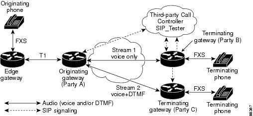
Edge Gateway
The edge gateway configuration is used to convert a foreign-exchange-station (FXS) interface to a T1 interface. It is not involved in media forking or VoIP.
Router# show running-config
Building configuration...
Current configuration : 4455 bytes
!
version 12.2
no service single-slot-reload-enable
service timestamps debug datetime msec
service timestamps log uptime
no service password-encryption
!
logging rate-limit console 10 except errors
!
voice-card 1
!
ip subnet-zero
!
ip domain-name example.com
ip name-server 172.26.11.21
!
no ip dhcp-client network-discovery
isdn switch-type primary-dms100
isdn voice-call-failure 0
call rsvp-sync
!
controller T1 1/0
framing esf
linecode b8zs
pri-group timeslots 1-24
!
controller T1 1/1
framing esf
linecode b8zs
pri-group timeslots 1-24
!
interface Serial1/0:23
no ip address
no logging event link-status
isdn switch-type primary-dms100
isdn incoming-voice voice
isdn T310 4000
no cdp enable
!
interface Serial1/1:23
no ip address
no logging event link-status
isdn switch-type primary-dms100
isdn incoming-voice voice
no fair-queue
no cdp enable
!
interface FastEthernet3/0
ip address 172.18.193.136 255.255.0.0
duplex auto
speed auto
!
ip classless
ip route 172.16.0.0 255.0.0.0 FastEthernet3/0
no ip http server
!
snmp-server packetsize 4096
snmp-server manager
!
voice-port 1/0:23
!
voice-port 1/1:23
!
voice-port 2/0/0
!
voice-port 2/0/1
!
voice-port 2/1/0
!
voice-port 2/1/1
!
dial-peer cor custom
!
dial-peer voice 5552 pots
destination-pattern 5552...
port 1/1:23
prefix 5552
!
dial-peer voice 5555 pots
destination-pattern 5555101
port 2/0/1
!
line con 0
exec-timeout 0 0
transport preferred none
line aux 0
line vty 0 4
exec-timeout 0 0
password password1
login
!
end
Party A
Router# show running-config
Building configuration...
Current configuration : 1864 bytes
!
version 12.2
service timestamps debug datetime msec
service timestamps log uptime
no service password-encryption
!
memory-size iomem 10
voice-card 1
codec complexity high
!
ip subnet-zero
!
ip domain-name example.com
ip name-server 172.26.11.21
!
isdn switch-type primary-dms100
isdn voice-call-failure 0
!
voice service voip
sip
!
no voice hpi capture buffer
no voice hpi capture destination
!
fax interface-type fax-mail
mta receive maximum-recipients 0
!
controller T1 1/0
framing esf
linecode b8zs
!
controller T1 1/1
framing esf
linecode b8zs
pri-group timeslots 1-24
!
interface Ethernet0/0
ip address 172.18.193.14 255.255.0.0
half-duplex
fair-queue 64 256 235
ip rsvp bandwidth 7500 7500
!
interface Ethernet0/1
no ip address
shutdown
half-duplex
!
interface Serial1/1:23
no ip address
no logging event link-status
isdn switch-type primary-dms100
isdn incoming-voice voice
no cdp enable
!
ip classless
ip route 0.0.0.0 0.0.0.0 172.18.193.1
no ip http server
!!
call rsvp-sync
!
voice-port 1/1:23
!
mgcp profile default
!
dial-peer cor custom
!
dial-peer voice 2100 voip
destination-pattern 55521..
session target ipv4:172.18.193.88
!
dial-peer voice 2200 voip
destination-pattern 55522..
session protocol sipv2
session target ipv4:172.18.207.18:5062
dtmf-relay rtp-nte
codec g711ulaw
!
dial-peer voice 9999 voip
destination-pattern 9999
session protocol sipv2
session target ipv4:172.18.207.18:5062
!
dial-peer voice 5557 pots
destination-pattern 55571..
direct-inward-dial
port 1/1:23
!
sip-ua
retry invite 3
retry response 3
retry bye 3
retry cancel 3
timers trying 501
!
line con 0
exec-timeout 0 0
transport preferred none
line aux 0
line vty 0 4
password password1
login
line vty 5 15
login
!
no scheduler allocate
!
end
Party B
Router# show running-config
Building configuration...
Current configuration : 1769 bytes
!
version 12.2
service timestamps debug datetime msec
service timestamps log uptime
no service password-encryption
!
memory-size iomem 10
clock timezone gmt 1
ip subnet-zero
!
ip domain-name example.com
ip name-server 172.26.11.21
!
interface FastEthernet0/0
ip address 172.18.193.88 255.255.0.0
no ip mroute-cache
duplex auto
speed auto
fair-queue 64 256 235
no cdp enable
ip rsvp bandwidth 7500 7500
!
ip classless
ip route 0.0.0.0 0.0.0.0 172.18.193.1
no ip http server
!
snmp-server engineID local 00000009020000107BDC8FA0
snmp-server community public RO
snmp-server packetsize 2048
call rsvp-sync
!
voice-port 1/0/0
no supervisory disconnect lcfo
!
voice-port 1/0/1
no supervisory disconnect lcfo
!
dial-peer cor custom
!
dial-peer voice 2100 pots
destination-pattern 5552100
port 1/0/0
!
dial-peer voice 2101 pots
destination-pattern 5552101
port 1/0/1
!
dial-peer voice 2200 pots
destination-pattern 5552200
port 1/0/0
!
dial-peer voice 2201 pots
destination-pattern 5552201
port 1/0/1
!
dial-peer voice 9999 voip
destination-pattern 9999
session protocol sipv2
session target ipv4:172.18.207.18:5062
codec g711ulaw
!
sip-ua
retry invite 3
retry response 3
retry bye 3
retry cancel 3
timers trying 501
!
line con 0
exec-timeout 0 0
transport preferred none
line aux 0
line vty 0 4
password password1
login
line vty 5 15
login
!
end
Party C
Router# show running-config
Building configuration...
Current configuration : 1638 bytes
!
version 12.2
service timestamps debug datetime msec
service timestamps log uptime
no service password-encryption
!
memory-size iomem 10
ip subnet-zero
!
ip domain-name example.com
ip name-server 172.26.11.21
!
interface Ethernet0/0
ip address 172.18.193.80 255.255.0.0
half-duplex
fair-queue 64 256 235
ip rsvp bandwidth 7500 7500
!
interface Ethernet0/1
no ip address
shutdown
half-duplex
!
ip classless
ip route 0.0.0.0 0.0.0.0 172.18.193.1
no ip http server
!
call rsvp-sync
!
voice-port 1/0/0
no supervisory disconnect lcfo
!
voice-port 1/0/1
no supervisory disconnect lcfo
dial-peer cor custom
!
dial-peer voice 3100 pots
destination-pattern 5553100
port 1/0/0
!
dial-peer voice 3101 pots
destination-pattern 5553101
port 1/0/1
!
dial-peer voice 3200 pots
destination-pattern 5553200
port 1/0/0
!
dial-peer voice 3201 pots
destination-pattern 5553201
port 1/0/1
!
dial-peer voice 9999 voip
destination-pattern 9999
session protocol sipv2
session target ipv4:172.18.207.18:5062
dtmf-relay rtp-nte
codec g711ulaw
!
sip-ua
retry invite 3
retry response 3
retry bye 3
retry cancel 3
!
line con 0
exec-timeout 0 0
transport preferred none
line aux 0
line vty 0 4
exec-timeout 0 0
password password1
login
transport input none
escape-character BREAK
line vty 5 15
login
!
end
Party A Initial-Call-Setup Trace
The following is the initial call-setup trace for Party A.
Router# debug ccsip message
*Mar 1 00:32:02.431: Sent:
INVITE sip:5552201@172.18.207.18:5062;user=phone SIP/2.0
Via: SIP/2.0/UDP 172.18.193.14:5060
From: "5555101" <sip:5555101@172.18.193.14>;tag=1D556B-24F1
To: <sip:5552201@172.18.207.18;user=phone>
Date: Mon, 01 Mar 1993 00:32:02 GMT
Call-ID: 1A3F2B6-14F311CC-801AECAF-10CC98B5@172.18.193.14
Supported: timer,100rel
Min-SE: 1800
Cisco-Guid: 27401485-351474124-2149117103-281843893
User-Agent: Cisco-SIPGateway/IOS-12.x
CSeq: 101 INVITE
Max-Forwards: 6
Timestamp: 730945922
Contact: <sip:5555101@172.18.193.14:5060;user=phone>
Expires: 180
Allow-Events: telephone-event
Content-Type: application/sdp
Content-Length: 299
v=0
o=CiscoSystemsSIP-GW-UserAgent 2763 7166 IN IP4 172.18.193.14
s=SIP Call
c=IN IP4 172.18.193.14
t=0 0
m=audio 16412 RTP/AVP 0 100 101
c=IN IP4 172.18.193.14
a=rtpmap:0 PCMU/8000
a=rtpmap:100 X-NSE/8000
a=fmtp:100 192-194
a=rtpmap:101 telephone-event/8000
a=fmtp:101 0-16
a=ptime:20
*Mar 1 00:32:02.499: Received:
SIP/2.0 183 Session Progress
Via: SIP/2.0/UDP 172.18.207.18:5062
From: "5555101" <sip:5555101@172.18.193.14;user=phone>;tag=1D556B-24F1
To: <sip:5552201@172.18.207.18;user=phone>;tag=tester-tag
Date: Mon, 01 Mar 1993 01:01:01 GMT
Call-ID: 1A3F2B6-14F311CC-801AECAF-10CC98B5@172.18.193.14
CSeq: 101 INVITE
Require: 100rel
RSeq: 5413
Contact: <sip:9999@172.18.207.18:5062;user=phone>
Content-Type: application/sdp
Content-Length: 223
v=0
o=SIP_Tester 1239625037 1770029373 IN IP4 172.18.207.18
s=SIP Prot Test Call
t=0 0
m=audio 17236 RTP/AVP 0 100
c=IN IP4 172.18.193.88
a=rtpmap:0 PCMU/8000
a=rtpmap:100 X-NSE/8000
a=fmtp:100 192-194
a=ptime:20
*Mar 1 00:32:02.539: Sent:
PRACK sip:9999@172.18.207.18:5062;user=phone SIP/2.0
Via: SIP/2.0/UDP 172.18.193.14:5060
From: "5555101" <sip:5555101@172.18.193.14>;tag=1D556B-24F1
To: <sip:5552201@172.18.207.18;user=phone>;tag=tester-tag
Date: Mon, 01 Mar 1993 00:32:02 GMT
Call-ID: 1A3F2B6-14F311CC-801AECAF-10CC98B5@172.18.193.14
CSeq: 102 PRACK
RAck: 5413 101 INVITE
Content-Length: 0
*Mar 1 00:32:02.563: Received:
SIP/2.0 200 OK
Via: SIP/2.0/UDP 172.18.207.18:5062
From: "5555101" <sip:5555101@172.18.193.14;user=phone>;tag=1D556B-24F1
To: <sip:5552201@172.18.207.18;user=phone>;tag=tester-tag
Date: Mon, 01 Mar 1993 01:01:01 GMT
Call-ID: 1A3F2B6-14F311CC-801AECAF-10CC98B5@172.18.193.14
CSeq: 102 PRACK
Contact: <sip:9999@172.18.207.18:5062;user=phone>
Content-Length: 0
*Mar 1 00:32:03.609: Received:
SIP/2.0 200 OK
Via: SIP/2.0/UDP 172.18.207.18:5062
From: "5555101" <sip:5555101@172.18.193.14;user=phone>;tag=1D556B-24F1
To: <sip:5552201@172.18.207.18;user=phone>;tag=tester-tag
Date: Mon, 01 Mar 1993 01:01:01 GMT
Call-ID: 1A3F2B6-14F311CC-801AECAF-10CC98B5@172.18.193.14
CSeq: 101 INVITE
Contact: <sip:9999@172.18.207.18:5062;user=phone>
Content-Type: application/sdp
Content-Length: 223
v=0
o=SIP_Tester 1239625037 1770029374 IN IP4 172.18.207.18
s=SIP Prot Test Call
t=0 0
m=audio 17236 RTP/AVP 0 100
c=IN IP4 172.18.193.88
a=rtpmap:0 PCMU/8000
a=rtpmap:100 X-NSE/8000
a=fmtp:100 192-194
a=ptime:20
*Mar 1 00:32:03.633: Sent:
ACK sip:9999@172.18.207.18:5062;user=phone SIP/2.0
Via: SIP/2.0/UDP 172.18.193.14:5060
From: "5555101" <sip:5555101@172.18.193.14>;tag=1D556B-24F1
To: <sip:5552201@172.18.207.18;user=phone>;tag=tester-tag
Date: Mon, 01 Mar 1993 00:32:02 GMT
Call-ID: 1A3F2B6-14F311CC-801AECAF-10CC98B5@172.18.193.14
Max-Forwards: 6
Content-Length: 0
CSeq: 101 ACK
Party B Initial-Call-Setup Trace
The following is the initial call-setup trace for Party B. Also, call status is displayed with the show sip-ua calls command.
Router# debug ccsip message
*Mar 1 00:43:13.655: Received:
INVITE sip:5552201@172.18.193.88;user=phone SIP/2.0
Via: SIP/2.0/UDP 172.18.207.18:5062
From: "SIP_Tester" <sip:9999@172.18.207.18:5062;user=phone>;tag=tester-tag
To: "5552201" <sip:5552201@172.18.193.88;user=phone>
Date: Mon, 01 Mar 1993 01:01:01 GMT
Call-ID: 487666621@172.18.207.18
Supported: 100rel
CSeq: 101 INVITE
Contact: <sip:9999@172.18.207.18:5062;user=phone>
Content-Type: application/sdp
Content-Length: 278
v=0
o=SIP_Tester 1818337819 831652457 IN IP4 172.18.207.18
s=SIP Prot Test Call
t=0 0
m=audio 16452 RTP/AVP 0 100 101
c=IN IP4 172.18.193.14
a=rtpmap:0 PCMU/8000
a=rtpmap:100 X-NSE/8000
a=fmtp:100 192-194
a=rtpmap:101 telephone-event/8000
a=fmtp:101 0-16
a=ptime:20
*Mar 1 00:43:13.683: Sent:
SIP/2.0 100 Trying
Via: SIP/2.0/UDP 172.18.207.18:5062
From: "SIP_Tester" <sip:9999@172.18.207.18:5062;user=phone>;tag=tester-tag
To: "5552201" <sip:5552201@172.18.193.88;user=phone>;tag=279390-CB
Date: Mon, 01 Mar 1993 00:43:13 gmt
Call-ID: 487666621@172.18.207.18
Server: Cisco-SIPGateway/IOS-12.x
CSeq: 101 INVITE
Allow-Events: telephone-event
Content-Length: 0
*Mar 1 00:43:13.715: Sent:
SIP/2.0 183 Session Progress
Via: SIP/2.0/UDP 172.18.207.18:5062
From: "SIP_Tester" <sip:9999@172.18.207.18:5062;user=phone>;tag=tester-tag
To: "5552201" <sip:5552201@172.18.193.88;user=phone>;tag=279390-CB
Date: Mon, 01 Mar 1993 00:43:13 gmt
Call-ID: 487666621@172.18.207.18
Server: Cisco-SIPGateway/IOS-12.x
CSeq: 101 INVITE
Require: 100rel
RSeq: 5450
Allow-Events: telephone-event
Contact: <sip:5552201@172.18.193.88:5060;user=phone>
Content-Type: application/sdp
Content-Disposition: session;handling=required
Content-Length: 243
v=0
o=CiscoSystemsSIP-GW-UserAgent 1886 7999 IN IP4 172.18.193.88
s=SIP Call
c=IN IP4 172.18.193.88
t=0 0
m=audio 17936 RTP/AVP 0 100
c=IN IP4 172.18.193.88
a=rtpmap:0 PCMU/8000
a=rtpmap:100 X-NSE/8000
a=fmtp:100 192-194
a=ptime:20
*Mar 1 00:43:13.779: Received:
PRACK sip:5552201@172.18.193.88;user=phone SIP/2.0
Via: SIP/2.0/UDP 172.18.207.18:5062
From: "SIP_Tester" <sip:9999@172.18.207.18:5062;user=phone>;tag=tester-tag
To: "5552201" <sip:5552201@172.18.193.88;user=phone>;tag=279390-CB
Date: Mon, 01 Mar 1993 01:01:01 GMT
Call-ID: 487666621@172.18.207.18
CSeq: 102 PRACK
RAck: 0 101 INVITE
Content-Length: 0
*Mar 1 00:43:13.791: Sent:
SIP/2.0 200 OK
Via: SIP/2.0/UDP 172.18.207.18:5062
From: "SIP_Tester" <sip:9999@172.18.207.18:5062;user=phone>;tag=tester-tag
To: "5552201" <sip:5552201@172.18.193.88;user=phone>;tag=279390-CB
Date: Mon, 01 Mar 1993 00:43:13 gmt
Call-ID: 487666621@172.18.207.18
Server: Cisco-SIPGateway/IOS-12.x
CSeq: 102 PRACK
Content-Length: 0
*Mar 1 00:43:17.251: Sent:
SIP/2.0 200 OK
Via: SIP/2.0/UDP 172.18.207.18:5062
From: "SIP_Tester" <sip:9999@172.18.207.18:5062;user=phone>;tag=tester-tag
To: "5552201" <sip:5552201@172.18.193.88;user=phone>;tag=279390-CB
Date: Mon, 01 Mar 1993 00:43:13 gmt
Call-ID: 487666621@172.18.207.18
Server: Cisco-SIPGateway/IOS-12.x
CSeq: 101 INVITE
Allow-Events: telephone-event
Contact: <sip:5552201@172.18.193.88:5060;user=phone>
Content-Type: application/sdp
Content-Length: 243
v=0
o=CiscoSystemsSIP-GW-UserAgent 1886 7999 IN IP4 172.18.193.88
s=SIP Call
c=IN IP4 172.18.193.88
t=0 0
m=audio 17936 RTP/AVP 0 100
c=IN IP4 172.18.193.88
a=rtpmap:0 PCMU/8000
a=rtpmap:100 X-NSE/8000
a=fmtp:100 192-194
a=ptime:20
*Mar 1 00:43:17.343: Received:
ACK sip:5552201@172.18.193.88;user=phone SIP/2.0
Via: SIP/2.0/UDP 172.18.207.18:5062
From: "SIP_Tester" <sip:9999@172.18.207.18:5062;user=phone>;tag=tester-tag
To: "5552201" <sip:5552201@172.18.193.88;user=phone>;tag=279390-CB
Date: Mon, 01 Mar 1993 01:01:01 GMT
Call-ID: 487666621@172.18.207.18
CSeq: 101 ACK
Content-Length: 0
Router# show sip-ua calls
SIP UAC CALL INFO
Number of UAC calls: 0
SIP UAS CALL INFO
Call 1
SIP Call ID : 487666621@172.18.207.18
State of the call : STATE_ACTIVE (6)
Substate of the call : SUBSTATE_NONE (0)
Calling Number : 9999
Called Number : 5552201
Bit Flags : 0x1212003A 0x20000
Source IP Address (Sig ): 172.18.193.88
Destn SIP Req Addr:Port : 172.18.207.18:5062
Destn SIP Resp Addr:Port: 172.18.207.18:5062
Destination Name : 172.18.207.18
Number of Media Streams : 1
Number of Active Streams: 1
RTP Fork Object : 0x0
Media Stream 1
State of the stream : STREAM_ACTIVE (5)
Stream Call ID : 9
Stream Type : voice-only (0)
Negotiated Codec : g711ulaw (160 bytes)
Codec Payload Type : 0
Negotiated Dtmf-relay : inband-voice (0)
Dtmf-relay Payload : 0
Media Source IP Addr:Port: 172.18.193.88:17936
Media Dest IP Addr:Port : 172.18.193.14:16452
Number of UAS calls: 1
Party A Add-Second-Stream Trace
The following is the second stream trace added by Party A. Also, call status is displayed with the show sip-ua calls command.
Router# debug ccsip message
*Mar 1 00:33:05.178: Received:
INVITE sip:5555101@172.18.193.14;user=phone SIP/2.0
Via: SIP/2.0/UDP 172.18.207.18:5062
From: <sip:5552201@172.18.207.18;user=phone>;tag=tester-tag
To: "5555101" <sip:5555101@172.18.193.14;user=phone>;tag=1D556B-24F1
Date: Mon, 01 Mar 1993 01:01:01 GMT
Call-ID: 1A3F2B6-14F311CC-801AECAF-10CC98B5@172.18.193.14
Supported: 100rel
CSeq: 101 INVITE
Contact: <sip:9999@172.18.207.18:5062;user=phone>
Content-Type: application/sdp
Content-Length: 635
v=0
o=SIP_Tester 1239625037 1770029375 IN IP4 172.18.207.18
s=SIP Prot Test Call
t=0 0
m=audio 17236 RTP/AVP 0 100
c=IN IP4 172.18.193.88
a=rtpmap:0 PCMU/8000
a=rtpmap:100 X-NSE/8000
a=fmtp:100 192-194
a=ptime:20
m=audio 17114 RTP/AVP 0 100 101 101 100
c=IN IP4 172.18.193.80
a=rtpmap:0 PCMU/8000
a=rtpmap:100 X-NSE/8000
a=fmtp:100 192-194
a=rtpmap:101 telephone-event/8000
a=fmtp:101 0-16
a=ptime:20
a=rtpmap:0 PCMU/8000
a=rtpmap:100 X-NSE/8000
a=fmtp:100 192-194
a=rtpmap:101 telephone-event/8000
a=fmtp:101 0-16
a=rtpmap:101 telephone-event/8000
a=fmtp:101 0-16
a=rtpmap:100 X-NSE/8000
a=fmtp:100 192-194
*Mar 1 00:33:05.222: Sent:
SIP/2.0 200 OK
Via: SIP/2.0/UDP 172.18.207.18:5062
From: <sip:5552201@172.18.207.18;user=phone>;tag=tester-tag
To: "5555101" <sip:5555101@172.18.193.14>;tag=1D556B-24F1
Date: Mon, 01 Mar 1993 00:33:05 GMT
Call-ID: 1A3F2B6-14F311CC-801AECAF-10CC98B5@172.18.193.14
Server: Cisco-SIPGateway/IOS-12.x
CSeq: 101 INVITE
Allow-Events: telephone-event
Contact: <sip:5555101@172.18.193.14:5060;user=phone>
Content-Type: application/sdp
Content-Length: 431
v=0
o=CiscoSystemsSIP-GW-UserAgent 2763 7167 IN IP4 172.18.193.14
s=SIP Call
c=IN IP4 172.18.193.14
t=0 0
m=audio 16412 RTP/AVP 0 100
c=IN IP4 172.18.193.14
a=rtpmap:0 PCMU/8000
a=rtpmap:100 X-NSE/8000
a=fmtp:100 192-194
a=ptime:20
m=audio 18802 RTP/AVP 0 101 100
c=IN IP4 172.18.193.14
a=rtpmap:0 PCMU/8000
a=rtpmap:101 telephone-event/8000
a=fmtp:101 0-16
a=rtpmap:100 X-NSE/8000
a=fmtp:100 192-194
a=ptime:20
*Mar 1 00:33:05.234: Received:
ACK sip:5555101@172.18.193.14;user=phone SIP/2.0
Via: SIP/2.0/UDP 172.18.207.18:5062
From: <sip:5552201@172.18.207.18;user=phone>;tag=tester-tag
To: "5555101" <sip:5555101@172.18.193.14;user=phone>;tag=1D556B-24F1
Date: Mon, 01 Mar 1993 01:01:01 GMT
Call-ID: 1A3F2B6-14F311CC-801AECAF-10CC98B5@172.18.193.14
CSeq: 101 ACK
Content-Length: 0
Router# show sip-ua calls
SIP UAC CALL INFO
Call 1
SIP Call ID : 1A3F2B6-14F311CC-801AECAF-10CC98B5@172.18.193.14
State of the call : STATE_ACTIVE (6)
Substate of the call : SUBSTATE_NONE (0)
Calling Number : 5555101
Called Number : 5552201
Bit Flags : 0x12120030 0x20000
Source IP Address (Sig ): 172.18.193.14
Destn SIP Req Addr:Port : 172.18.207.18:5062
Destn SIP Resp Addr:Port: 172.18.207.18:5062
Destination Name : 172.18.207.18
Number of Media Streams : 2
Number of Active Streams: 2
RTP Fork Object : 0x83064DC8
Media Stream 1
State of the stream : STREAM_ACTIVE (5)
Stream Call ID : 11
Stream Type : voice-only (0)
Negotiated Codec : g711ulaw (160 bytes)
Codec Payload Type : 0
Negotiated Dtmf-relay : inband-voice (0)
Dtmf-relay Payload : 0
Media Source IP Addr:Port: 172.18.193.14:16412
Media Dest IP Addr:Port : 172.18.193.88:17236
Media Stream 2
State of the stream : STREAM_ACTIVE (5)
Stream Call ID : 12
Stream Type : voice+dtmf (1)
Negotiated Codec : g711ulaw (160 bytes)
Codec Payload Type : 0
Negotiated Dtmf-relay : rtp-nte (6)
Dtmf-relay Payload : 101
Media Source IP Addr:Port: 172.18.193.14:18802
Media Dest IP Addr:Port : 172.18.193.80:17114
Number of UAC calls: 1
SIP UAS CALL INFO
Number of UAS calls: 0
Party C Add-Second-Stream Trace
The following is the second stream trace added by Party C. Also, call status is displayed with the show sip-ua calls command.
Router# debug ccsip message
*Mar 1 00:44:19.763: Received:
INVITE sip:5553201@172.18.193.80;user=phone SIP/2.0
Via: SIP/2.0/UDP 172.18.207.18:5062
From: "SIP_Tester" <sip:9999@172.18.207.18:5062;user=phone>;tag=tester-tag
To: "5553201" <sip:5553201@172.18.193.80;user=phone>
Date: Mon, 01 Mar 1993 01:01:01 GMT
Call-ID: 2108310431@172.18.207.18
Supported: 100rel
CSeq: 101 INVITE
Contact: <sip:9999@172.18.207.18:5062;user=phone>
Content-Length: 0
*Mar 1 00:44:19.792: Sent:
SIP/2.0 100 Trying
Via: SIP/2.0/UDP 172.18.207.18:5062
From: "SIP_Tester" <sip:9999@172.18.207.18:5062;user=phone>;tag=tester-tag
To: "5553201" <sip:5553201@172.18.193.80;user=phone>;tag=2895C8-53B
Date: Mon, 01 Mar 1993 00:44:19 GMT
Call-ID: 2108310431@172.18.207.18
Server: Cisco-SIPGateway/IOS-12.x
CSeq: 101 INVITE
Allow-Events: telephone-event
Content-Length: 0
*Mar 1 00:44:19.828: Sent:
SIP/2.0 183 Session Progress
Via: SIP/2.0/UDP 172.18.207.18:5062
From: "SIP_Tester" <sip:9999@172.18.207.18:5062;user=phone>;tag=tester-tag
To: "5553201" <sip:5553201@172.18.193.80;user=phone>;tag=2895C8-53B
Date: Mon, 01 Mar 1993 00:44:19 GMT
Call-ID: 2108310431@172.18.207.18
Server: Cisco-SIPGateway/IOS-12.x
CSeq: 101 INVITE
Require: 100rel
RSeq: 6083
Allow-Events: telephone-event
Contact: <sip:5553201@172.18.193.80:5060;user=phone>
Content-Type: application/sdp
Content-Disposition: session;handling=required
Content-Length: 523
v=0
o=CiscoSystemsSIP-GW-UserAgent 8259 5683 IN IP4 172.18.193.80
s=SIP Call
c=IN IP4 172.18.193.80
t=0 0
m=audio 18988 RTP/AVP 0 100 101
c=IN IP4 172.18.193.80
a=rtpmap:0 PCMU/8000
a=rtpmap:100 X-NSE/8000
a=fmtp:100 192-194
a=rtpmap:101 telephone-event/8000
a=fmtp:101 0-16
a=ptime:20
*Mar 1 00:44:20.985: Sent:
SIP/2.0 200 OK
Via: SIP/2.0/UDP 172.18.207.18:5062
From: "SIP_Tester" <sip:9999@172.18.207.18:5062;user=phone>;tag=tester-tag
To: "5553201" <sip:5553201@172.18.193.80;user=phone>;tag=2895C8-53B
Date: Mon, 01 Mar 1993 00:44:19 GMT
Call-ID: 2108310431@172.18.207.18
Server: Cisco-SIPGateway/IOS-12.x
CSeq: 101 INVITE
Allow-Events: telephone-event
Contact: <sip:5553201@172.18.193.80:5060;user=phone>
Content-Type: application/sdp
Content-Length: 523
v=0
o=CiscoSystemsSIP-GW-UserAgent 8259 5683 IN IP4 172.18.193.80
s=SIP Call
c=IN IP4 172.18.193.80
t=0 0
m=audio 18988 RTP/AVP 0 100 101
c=IN IP4 172.18.193.80
a=rtpmap:0 PCMU/8000
a=rtpmap:100 X-NSE/8000
a=fmtp:100 192-194
a=rtpmap:101 telephone-event/8000
a=fmtp:101 0-16
a=ptime:20
*Mar 1 00:44:20.997: Received:
ACK sip:5553201@172.18.193.80;user=phone SIP/2.0
Via: SIP/2.0/UDP 172.18.207.18:5062
From: "SIP_Tester" <sip:9999@172.18.207.18:5062;user=phone>;tag=tester-tag
To: "5553201" <sip:5553201@172.18.193.80;user=phone>;tag=2895C8-53B
Date: Mon, 01 Mar 1993 01:01:01 GMT
Call-ID: 2108310431@172.18.207.18
CSeq: 101 ACK
Content-Type: application/sdp
Content-Length: 277
v=0
o=SIP_Tester 2029259292 42666129 IN IP4 172.18.207.18
s=SIP Prot Test Call
t=0 0
m=audio 16728 RTP/AVP 0 101 100
c=IN IP4 172.18.193.14
a=rtpmap:0 PCMU/8000
a=rtpmap:101 telephone-event/8000
a=fmtp:101 0-16
a=rtpmap:100 X-NSE/8000
a=fmtp:100 192-194
a=ptime:20
Router# show sip-ua calls
SIP UAC CALL INFO
Number of UAC calls: 0
SIP UAS CALL INFO
Call 1
SIP Call ID : 186464186@172.18.207.18
State of the call : STATE_ACTIVE (6)
Substate of the call : SUBSTATE_NONE (0)
Calling Number : 9999
Called Number : 5553201
Bit Flags : 0x1212003A 0x20000
Source IP Address (Sig ): 172.18.193.80
Destn SIP Req Addr:Port : 172.18.207.18:5062
Destn SIP Resp Addr:Port: 172.18.207.18:5062
Destination Name : 172.18.207.18
Number of Media Streams : 1
Number of Active Streams: 1
RTP Fork Object : 0x0
Media Stream 1
State of the stream : STREAM_ACTIVE (5)
Stream Call ID : 7
Stream Type : voice+dtmf (1)
Negotiated Codec : g711ulaw (160 bytes)
Codec Payload Type : 0
Negotiated Dtmf-relay : rtp-nte (6)
Dtmf-relay Payload : 101
Media Source IP Addr:Port: 172.18.193.80:19352
Media Dest IP Addr:Port : 172.18.193.14:16770
Number of UAS calls: 1
Additional References
The following sections provide references related to the SIP Connection-Oriented Media, Forking, and MLPP features.
Related Documents
|
|
|
|---|---|
Cisco IOS commands |
|
SIP commands |
|
Tcl IVR and VoiceXML |
|
Cisco VoiceXML |
Standards
|
|
|
|---|---|
No new or modified standards are supported, and support for existing standards has not been modified. |
— |
MIBs
RFCs
|
|
|
|---|---|
No new or modified RFCs are supported, and support for existing RFCs has not been modified. |
— |
 Feedback