The documentation set for this product strives to use bias-free language. For the purposes of this documentation set, bias-free is defined as language that does not imply discrimination based on age, disability, gender, racial identity, ethnic identity, sexual orientation, socioeconomic status, and intersectionality. Exceptions may be present in the documentation due to language that is hardcoded in the user interfaces of the product software, language used based on RFP documentation, or language that is used by a referenced third-party product. Learn more about how Cisco is using Inclusive Language.
This chapter describes how to configure connections through Link Access Procedure, Balanced (LAPB) connections and X.25 networks.
LAPB tasks are presented first for users who only want to configure a simple, reliable serial encapsulation method. For a
complete description of the commands mentioned in this chapter, refer to the chapter "X.25 and LAPB Commands " in the
Cisco IOS Wide-AreaNetworkingCommandReference.
For information on the following related topics, see the corresponding Cisco publications:
Task
Resource
Configuring PAD access
"Configuring the Cisco PAD Facility for X.25 Connections" chapter in the
Cisco IOS Terminal Services Configuration Guide
Translating between an X.25 PAD connection and another protocol
Cisco IOS
Terminal Services Command Reference (commands in alphabetical order.
Finding Feature Information
Your software release may not support all the features documented in this module. For the latest caveats and feature information,
see Bug Search Tool and the release notes for your platform and software release. To find information about the features documented in this module,
and to see a list of the releases in which each feature is supported, see the feature information table.
Use Cisco Feature Navigator to find information about platform support and Cisco software image support. To access Cisco Feature
Navigator, go to www.cisco.com/go/cfn. An account on Cisco.com is not required.
Information about LAPB and X.25
LAPB Overview
You use LAPB as a serial encapsulation method only if you have a private serial line. You must use one of the X.25 packet-level
encapsulations when attaching to an X.25 network.
LAPB standards distinguish between the following two types of hosts:
Data terminal equipment (DTE)
Data circuit-terminating equipment (DCE)
At Level 2 (data link layer) in the OSI model, LAPB allows orderly and reliable exchange of data between a DTE and a DCE device.
A router using LAPB encapsulation can act as a DTE or DCE at the protocol level, which is distinct from the hardware DTE or
DCE identity.
Using LAPB under heavy traffic conditions can result in greater throughput than is possible using High-Level Data Link Control
(HDLC) encapsulation. When LAPB detects a missing frame, the router resends the frame instead of waiting for the higher layers
to recover the lost information. This behavior is useful only if the host timers are relatively slow. In the case of quickly
expiring host timers, however, LAPB spends much time sending host retransmissions. If the line is not busy with data traffic,
HDLC encapsulation is more efficient than LAPB. When long-delay satellite links are used, for example, the lockstep behavior
of LAPB makes HDLC encapsulation the better choice.
Modifying LAPB Protocol Parameters
LAPB specifies methods for exchanging data (frames), detecting out-of-sequence or missing frames, retransmitting frames,
and acknowledging frames. Several protocol parameters can be modified to change LAPB protocol performance on a particular
link. Because X.25 operates the Packet Level Protocol (PLP) on top of the LAPB protocol, these tasks apply to both X.25 links
and LAPB links. The parameters and their default values are summarized in the table below. Detailed descriptions of each parameter
are given after the table.
Table 1. LAPB Parameters
Command
Purpose (LAPB Parameter)
Values or Ranges
Default
lapb modulo modulus
Sets the modulo.
8 or 128
8
lapb k window-size
Sets the window size (K).
1- (modulo minus 1) frames
7
lapb n1 bits
Sets the maximum bits per frame (N1).
Bits (multiple of 8)
Based on hardware MTU and protocol overhead
lapb n2 tries
Sets the count for sending frames (N2).
1-255 tries
20
lapb t1 milliseconds
Sets the retransmission timer (T1).
1-64000 milliseconds
3000
lapb interface-outage milliseconds
Sets the hardware outage period.
0 (disabled)
lapb t4 seconds
Sets the idle link period (T4).
0 (disabled)
The following sections provide more information about the LAPB parameters in the table above:
LAPB modulo--The LAPB modulo determines the operating mode. Modulo 8 (basic mode) is widely available because it is required
for all standard LAPB implementations and is sufficient for most links. Modulo 128 (extended mode) can achieve greater throughput
on high-speed links that have a low error rate (satellite links) by increasing the number of frames that can be sent before
the sending device must wait for acknowledgment (as configured by LAPB parameter K).
LAPB parameter K--LAPB K must be at most one less than the operating modulo. Modulo 8 links can send seven frames before
an acknowledgment must be received by the sending device; modulo 128 links can send as many as 127 frames. By default, LAPB
links use the basic mode with a window of 7.
LAPB N1--When you configure a connection to an X.25 network, use the N1 parameter value set by the network administrator.
This value is the maximum number of bits in a LAPB frame, which determines the maximum size of an X.25 packet. When you use
LAPB over leased lines, the N1 parameter should be eight times the hardware MTU size plus any protocol overhead. The LAPB
N1 range is dynamically calculated by the Cisco IOS software whenever an MTU change, a Layer 2/Layer 3 modulo change, or a
compression change occurs on a LAPB interface.
Caution
The LAPB N1 parameter provides little benefit beyond the interface MTU, and can easily cause link failures if misconfigured.
Cisco recommends that you leave this parameter at its default value.
LAPB N2--The transmit counter (N2) is the number of unsuccessful transmit attempts that are made before the link is declared
down.
LAPB T1--The retransmission timer (T1) determines how long a sent frame can remain unacknowledged before the Cisco IOS software
polls for an acknowledgment. For X.25 networks, the retransmission timer setting should match that of the network.
For leased-line circuits, the T1 timer setting is critical because the design of LAPB assumes that a frame has been lost
if it is not acknowledged within period T1. The timer setting must be large enough to permit a maximum-sized frame to complete
one round trip on the link. If the timer setting is too small, the software will poll before the acknowledgment frame can
return, which may result in duplicated frames and severe protocol problems. If the timer setting is too large, the software
waits longer than necessary before requesting an acknowledgment, slowing throughput.
LAPB interface outage--Another LAPB timer function that allows brief hardware failures while the protocol is up, without
requiring a protocol reset. When a brief hardware outage occurs, the link continues uninterrupted if the outage corrects before
the specified outage period expires.
LAPB T4--The LAPB standards define a timer to detect unsignaled link failures (T4). The T4 timer resets every time a frame
is received from the partner on the link. If the T4 timer expires, a Receiver Ready frame with the Poll bit set is sent to
the partner, which is required to respond. If the partner does not respond, the standard polling mechanism is used to determine
whether the link is down. The period of T4 must be greater than the period of T1.
A router using X.25 Level 3 encapsulation can act as a DTE or DCE protocol device (according to the needs of your X.25 service
supplier), can use DDN or BFE encapsulation, or can use the Internet Engineering Task Force (IETF) standard encapsulation,
as specified by RFC 1356.
Because the default serial encapsulation is HDLC, you must explicitly configure an X.25 encapsulation method.
Note
We recommend that you use the no encapsulation x25 command to remove all X.25 configurations from the interface before changing the encapsulation.
Typically a public data network (PDN) will require attachment as a DTE device. (This requirement is distinct from the hardware
interface DTE or DCE identity.) The default mode is DTE, and the default encapsulation method is the Cisco pre-IETF method.
If either DDN or BFE operation is needed, it must be explicitly configured. For an example of configuring X.25 DTE operation,
see the section "Typical X.25 Configuration Example" later in this chapter.
Virtual Circuit Ranges
X.25 maintains multiple connections--virtual circuits (VCs) or logical circuits (LCs)--over one physical link between a DTE
and a DCE device. X.25 can maintain up to 4095 VCs. A VC is identified by its logical channel identifier (LCI) or virtual
circuit number (VCN).
Note
Many documents use the terms virtual circuit
and LC
, VCN
, LCN
, and LCI
interchangeably. Each of these terms refers to the VC number.
An important part of X.25 operation is the range of VC numbers. These numbers are broken into the following four ranges:
Permanent virtual circuits (PVCs)
Incoming-only circuits
Two-way circuits
Outgoing-only circuits
The incoming-only, two-way, and outgoing-only ranges define the VC numbers over which a switched virtual circuit (SVC) can
be established by the placement of an X.25 call, much as a telephone network establishes a switched voice circuit when a call
is placed.
The rules about DCE and DTE devices initiating calls are as follows:
Only the DCE can initiate a call in the incoming-only range.
Only the DTE can initiate a call in the outgoing-only range.
Both the DCE and DTE can initiate a call in the two-way range.
Note
The International Telecommunication Union-Telecommunication Standardization Sector (ITU-T) functions in place of the former
Consultative Committee for International Telegraph and Telephone (CCITT). ITU-T Recommendation X.25
defines "incoming" and "outgoing" in relation to the DTE or DCE interface role. Cisco documentation uses the more intuitive
sense. Unless the ITU-T sense is explicitly referenced, a call received from the interface is an incomingcall
and a call sent out to the interface is an outgoingcall
.
There is no difference in the operation of SVCs in the different ranges except the restrictions on which device can initiate
a call. These ranges can be used to prevent one side from monopolizing the VCs, which is important for X.25 interfaces with
a small number of SVCs available. Six X.25 parameters define the upper and lower limit of each of the three SVC ranges. These
ranges cannot overlap. A PVC must be assigned a number lower than those assigned to the SVC ranges.
Note
Because X.25 requires the DTE and DCE devices to have identical VC ranges, changes you make to the VC range limits when the
interface is up are held until X.25 restarts the packet service.
Packet-Numbering Modulo
The Cisco implementation of X.25 supports modulo 8 (default) and modulo 128 packet sequence numbering.
Note
Because X.25 requires the DTE and DCE devices to have identical modulos, changes you make to the modulo when the interface
is up remain until X.25 restarts the packet service.
The X.25 modulo and the LAPB modulo are distinct and serve different purposes. LAPB modulo 128 (or extended mode) can be used
to achieve higher throughput across the DTE or DCE interface, which affects only the local point of attachment. X.25 PLP modulo
128 can be used to achieve higher end-to-end throughput for VCs by allowing more data packets to be in transit across the
X.25 network.
X.121 Address
If your router does not originate or terminate calls but only participates in X.25 switching, this task is optional. However,
if your router is attached to a PDN, you must set the interface X.121 address assigned by the X.25 network service provider.
Interfaces that use the DDN or BFE mode will have an X.121 address generated from the interface IP address; for correct DDN
or BFE operation, any such X.121 address must not be modified.
X.25 Switch Local Acknowledgment
X.25 switch local acknowledgment allows you the choice of configuring local or end-to-end acknowledgment on your router.
End-to-end acknowledgment can result in lower overall throughput and restrictive performance because an endpoint can only
have a limited number of its packets in transit at any given time. End-to-end acknowledgment cannot send more packets until
all have been acknowledged by the transmission and receipt of the delivery-confirming packet containing the D-bit.
Local acknowledgment means that the Cisco router can send acknowledgments for packets that do not have the D-bit set, before
receiving an acknowledgment from the interface to which the packet was forwarded. This results in higher throughput of packets
because acknowledgment is sent between local hops much faster and more efficiently than between end-to-end hops.
The figure below shows the Cisco router receiving packets from DTE A destined for DTE B. Without local acknowledgment enabled,
the router forwards packets to the X.25 network and then forwards acknowledgments from the network back to DTE A. With local
acknowledgment enabled, the router can acknowledge packets received from DTE A before it has received acknowledgments from
the network for the forwarded packets. In this illustration, the X.25 network may also generate local acknowledgments.
Figure 1. Local Acknowledgment Between DTE A and DTE B
Flow Control Parameter Negotiation
Flow control is an X.25 optional user facility. When the x25 subscribe flow-control command is used, it permits flow control parameter negotiation of packet sizes and window sizes. This command can be altered
to one of three states: default behavior (no x25 subscribe flow-control ), facilities always included, or facilities never included (flow control parameter negotiation is not enabled). By default, these flow control parameter negotiation facilities
are included in call setup (outgoing) packets only when their values differ from the default values.
When flow control parameter negotiation is enabled, the x25 subscribe windowsize and x25 subscribe packetsize commands allow you to configure flow control restrictions by specifying window size and packet size ranges for permitted
and target values. A value that cannot be negotiated into the permitted range is treated as illegal, causing the call to fail.
The router first attempts values within the target range, but allows values outside the target range to be considered as long
as the range complies with procedures defined in the ITU-T Recommendation X.25
. With this feature, the Cisco router allows different flow control value configurations and acceptable window and packet
size formats for both DTE devices.
The ability to disable flow control parameter negotiation provides compatibility with equipment that does not support flow
control parameter negotiation. Similarly, forcing flow control parameter negotiation provides compatibility with devices that
require the flow control parameter negotiation facilities to be present in all calls.
To control packet transmission flow values on the interface, use one or more of the flow control commands--x25 subscribe flow-control , x25 subscribe windowsize , or x25 subscribe packetsize --in interface configuration mode.
The flow control subscription commands may be applied to an X.25 interface, to an X.25 profile, or to a LAN interface on which
the cmns enable command has been configured. For X.25 over TCP (XOT), the flow control parameter negotiation facilities are always included
(the equivalent of x25 subscribe flow-control always ).
Default Flow Control Values
Setting correct default flow control parameters of window size and packet size is essential for correct operation of the
link because X.25 is a strongly flow controlled protocol. Mismatched default flow control values will cause X.25 local procedure
errors, evidenced by Clear and Reset events.
Note
Because X.25 requires the DTE and DCE devices to have identical default maximum packet sizes and default window sizes, changes
made to the window and packet sizes when the interface is up are held until X.25 restarts the packet service.
Default Window Sizes
X.25 networks have a default input and output window size (the default is 2) that is defined by your network administrator.
You must set the Cisco IOS software default input and output window sizes to match those of the network. These defaults are
the values that an SVC takes on if it is set up without explicitly negotiating its window sizes. Any PVC also uses these default
values unless different values are configured.
Default Packet Sizes
X.25 networks have a default maximum input and output packet size (the default is 128) that is defined by your network administrator.
You must set the Cisco IOS software default input and output maximum packet sizes to match those of the network. These defaults
are the values that an SVC takes on if it is set up without explicit negotiatiation of its maximum packet sizes. Any PVC also
uses these default values unless different values are configured.
To send a packet larger than the agreed-on X.25 packet size over an X.25 VC, the Cisco IOS software must break the packet
into two or more X.25 packets with the M-bit ("more data" bit) set. The receiving device collects all packets in the M-bit
sequence and reassembles them into the original packet.
It is possible to define default packet sizes that cannot be supported by the lower layer (see the LAPB N1 parameter). However,
the router will negotiate lower maximum packet sizes for all SVCs so the agreed-on sizes can be carried. The Cisco IOS software
will also refuse a PVC configuration if the resulting maximum packet sizes cannot be supported by the lower layer.
Asymmetrical Flow Control
Asymmetrical flow control is supported by the permitted configuration of asymmetrical window and packet sizes. For data flow
from a channel with a smaller packet size than its outbound channel, the switch may combine data packets, and for a channel
with a larger packet size than its outbound channel, the switch will fragment the packets.
The figure below shows asymmetrical configuration of the Cisco router. DTE A (window size 3; packet size 128) and DTE B (window
size 5; packet size 256) are able to communicate despite differing window and packet sizes.
Figure 2. Asymmetrical Window and Packet Sizes Between DTE A and DTE B
To use asymmetrical flow control effectively, use the
x25 subscribe flow-control never command to disable flow control parameter negotiation, and use the
x25 routing acknowledge local command to enable local acknowledgment.
X.25 Interface Parameters
Some X.25 applications have unusual or special needs. Several X.25 parameters are available to modify X.25 behavior for these
applications.
X.25 Failover
Multiple routes can be configured in an X.25 routing table to allow one or more secondary or backup interfaces to be used
when a preferred (primary) interface is not usable. Routes are examined in the order in which they appear in the X.25 routing
table, and the first matching route is taken. However, since X.25 traffic is circuit-oriented, once a connection is established
via the secondary interface, the connection remains active even after the primary interface returns to service. This situation
is undesirable when the path via the secondary interface is slower or more expensive than the path via the primary interface.
X.25 Failover enables you to configure the secondary or backup interface to reset once the primary interface has come back
up and remained operational for a specified amount of time, terminating any connections that are still using the secondary
interface. Subsequent calls will then be forwarded over the preferred interface.
X.25 Failover supports Annex G (X.25 over Frame Relay), but it does not support XOT.
You can configure X.25 Failover on an X.25 interface or X.25 profile.
X.25 Level 3 Timers
The X.25 Level 3 event timers determine how long the Cisco IOS software waits for acknowledgment of control packets. You can
set these timers independently. Only those timers that apply to the interface are configurable. (A DTE interface does not
have the T1x
timers, and a DCE interface does not have the T2x
timers.)
X.25 Addresses
When you establish SVCs, X.25 uses addresses in the form defined by ITU-T Recommendation X.121
(or simply an "X.121 address"). An X.121 address has from zero to 15 digits. Because of the importance of addressing to call
setup, several interface addressing features are available for X.25.
The X.121 address of an X.25 interface is used when it is the source or destination of an X.25 call. The X.25 call setup procedure
identifies both the calling (source) and the called (destination) X.121 addresses. When an interface is the source of a call,
it encodes the interface X.121 address as the source address. An interface determines that it is the destination of a received
call if the destination address matches the address of the interface.
Cisco IOS X.25 software can also route X.25 calls, which involves placing and accepting calls, but the router is neither the
source nor the destination for these calls. Routing X.25 does not modify the source or destination addresses, thus preserving
the addresses specified by the source host. Routed (switched) X.25 simply connects two logical X.25 channels to complete an
X.25 VC. An X.25 VC, then, is a connection between two hosts (the source host and the destination host) that is switched between
zero or more routed X.25 links.
The null X.121 address (the X.121 address that has zero digits) is a special case. The router acts as the destination host
for any call it receives that has the null destination address.
A subaddress is an X.121 address that matches the digits defined for the X.121 address of the interface, but has one or more
additional digits after the base address. X.25 acts as the destination host for an incoming PAD call with a destination that
is a subaddress of the address of the interface; the trailing digits specify which line a PAD connection is requesting. This
feature is described in the chapter "Configuring Protocol Translation and Virtual Asynchronous Devices" in the Cisco IOS Terminal Services Configuration Guide
. Other calls that use a subaddress can be accepted if the trailing digit or digits are zeros; otherwise, the router will
not act as the destination host of the call.
Interface Alias Address
You can supply alias X.121 addresses for an interface. Supplying alias addresses allows the interface to act as the destination
host for calls having a destination address that is neither the address of the interface, an allowed subaddress of the interface,
nor the null address.
Local processing (for example, IP encapsulation) can be performed only for incoming calls whose destination X.121 address
matches the serial interface or alias of the interface.
Suppressing or Replacing the Calling Address
Some attachments require that no calling (source) address be presented in outgoing calls. This requirement is called suppressingthe calling address
. When attached to a PDN, X.25 may need to ensure that outgoing calls use only the assigned X.121 address for the calling
(source) address. Routed X.25 normally uses the original source address. Although individual X.25 route configurations can
modify the source address, Cisco provides a simple command to force the use of the interface address in all calls sent; this
requirement is called replacing the calling address
.
Suppressing the Called Address
Some attachments require that no called (destination) address be presented in outgoing calls; this requirement is called suppressing the called address
.
Default VC Protocol
The Call Request packet that sets up a VC can encode a field called the Call User Data (CUD) field. Typically the first few
bytes of the CUD field identify which high-level protocol is carried by the VC. The router, when acting as a destination host,
normally refuses a call if the CUD is absent or the protocol identification is not recognized. The PAD protocol, however,
specifies that unidentified calls be treated as PAD connection requests. Other applications require that they be treated as
IP encapsulation connection requests, in accordance with RFC 877, A Standard for the Transmission of IP Datagrams over Public Data Networks
.
Disabling PLP Restarts
By default, a PLP restart is performed when the link level resets (for example, when LAPB reconnects). Although PLP restarts
can be disabled for those few networks that do not allow restarts, we do not recommend disabling these restarts because doing
so can cause anomalous packet layer behavior.
Caution
Very few networks require this feature. Cisco does not recommend that it be enabled except when you are attaching to a network
that requires it.
X.25 Datagram Transport
Overview
X.25 support is most commonly configured as a transport for datagrams across an X.25 network. Datagram transport (or encapsulation)
is a cooperative effort between two hosts communicating across an X.25 network. You configure datagram transport by establishing
a mapping on the encapsulating interface between the protocol address of the far host (for example, IP ) and its X.121 address.
Because the call identifies the protocol that the VC will carry (by encoding a Protocol Identifier, or PID, in the first few
bytes of the CUD field), the terminating host can accept the call if it is configured to exchange the identified traffic with
the source host.
The figure below illustrates two routers sending datagrams across an X.25 PDN.
Figure 3. Transporting LAN Protocols Across an X.25 PDN
Point-to-Point and Multipoint Subinterfaces
Subinterfaces are virtual interfaces that can be used to connect several networks to each other through a single physical
interface. Subinterfaces are made available on Cisco routers because routing protocols, especially those using the split horizon
principle, may need help to determine which hosts need a routing update. The split horizon principle, which allows routing
updates to be distributed to other routed interfaces except the interface on which the routing update was received, works
well in a LAN environment in which other routers reached by the interface have already received the routing update.
However, in a WAN environment using connection-oriented interfaces (such as X.25 ), other routers reached by the same physical
interface might not have received the routing update. Rather than forcing you to connect routers by separate physical interfaces,
Cisco provides subinterfaces that are treated as separate interfaces. You can separate hosts into subinterfaces on a physical
interface, X.25 is unaffected, and routing processes recognize each subinterface as a separate source of routing updates,
so all subinterfaces are eligible to receive routing updates.
There are two types of subinterfaces: point-to-point and multipoint. Subinterfaces are implicitly multipoint unless configured
as point-to-point.
A point-to-point subinterface is used to encapsulate one or more protocols between two hosts. An X.25 point-to-point subinterface
will accept only a single encapsulation command (such as the x25 map or x25 pvc command) for a given protocol, so there can be only one destination for the protocol. (However, you can use multiple encapsulation
commands, one for each protocol, or multiple protocols for one map or PVC.) All protocol traffic routed to a point-to-point
subinterface is forwarded to the one destination host defined for the protocol. (Because only one destination is defined for
the interface, the routing process need not consult the destination address in the datagrams.)
A multipoint subinterface is used to connect one or more hosts for a given protocol. There is no restriction on the number
of encapsulation commands that can be configured on a multipoint subinterface. Because the hosts appear on the same subinterface,
they are not relying on the router to distribute routing updates among them. When a routing process forwards a datagram to
a multipoint subinterface, the X.25 encapsulation process must be able to map the destination address of the datagram to a
configured encapsulation command. If the routing process cannot find a map for the datagram destination address, the encapsulation
will fail.
Note
Because of the complex operations dependent on a subinterface and its type, the router will not allow a subinterface’s type
to be changed, nor can a subinterface with the same number be reestablished once it has been deleted. After a subinterface
has been deleted, you must reload the Cisco IOS software (by using the reload command) to remove all internal references. However, you can easily reconstitute the deleted subinterface by using a different
subinterface number.
For more information about configuring subinterfaces, refer to the chapter "Configuring Serial Interfaces" in the Cisco IOS Interface Configuration Guide
.
When configuring IP routing over X.25, you might need to make adjustments to accommodate split horizon effects. Refer to the
chapter "Configuring RIP" in the Cisco IOS IP Configuration Guide
for details about possible split horizon conflicts. By default, split horizon is enabled for X.25 attachments.
Mapping Protocol Addresses to X.121 Addresses
Understanding Protocol Encapsulation for Single-Protocol
Cisco has long supported encapsulation of a number of datagram protocols across X.25, using a standard method when available
or a proprietary method when necessary. These traditional methods assign a protocol to each VC. If more than one protocol
is carried between the router and a given host, each active protocol will have at least one VC dedicated to carrying its datagrams.
The Cisco IOS software can be configured to use any of the available encapsulation methods with a particular host.
After you establish an encapsulation VC using any method, the Cisco IOS software sends and receives a datagram by simply fragmenting
it into and reassembling it from an X.25 complete packet sequence. An X.25 complete packet sequence is one or more X.25 data
packets that have the M-bit set in all but the last packet. A VC that can carry multiple protocols includes protocol identification
data as well as the protocol data at the start of each complete packet sequence.
Understanding Protocol Identification
This section contains background material only.
The various methods and protocols used in X.25 SVC encapsulation are identified in a specific field of the call packet; this
field is defined by X.25 to carry CUD. Only PVCs do not use CUD to identify their encapsulation (because PVCs do not use the
X.25 call setup procedures).
The primary difference between the available Cisco and IETF encapsulation methods is the specific value used to identify
a protocol. When any of the methods establishes a VC for carrying a single protocol, the protocol is identified in the call
packet by the CUD.
The table below summarizes the values used in the CUD field to identify protocols.
1 The use of 0xCC for IP is backward-compatible with RFC 877, IP encapsulation [RFC:08] RFC 877.
2 The use of 0x01 00 00 00 for PAD is defined by ITU-T Recommendation X.29 .
Note
IP datagrams can be identified with a 1-byte identification (0xCC) or a 6-byte identification (0x80 followed by the 5-byte
SNAP encoding). The 1-byte encoding is used by default, although the SNAP encoding can be configured.
Mapping Datagram Addresses to X.25 Hosts
Encapsulation is a cooperative process between the router and another X.25 host. Because X.25 hosts are reached with an X.121
address (an X.121 address has 0 to 15 decimal digits), the router must have a means to map protocols and addresses of the
host to its X.121 address.
Each encapsulating X.25 interface must be configured with the relevant datagram parameters. For example, an interface that
encapsulates IP typically will have an IP address.
A router set up for DDN or BFE service uses a dynamic mapping technique to convert between IP and X.121 addresses. These techniques
have been designed specifically for attachment to the DDN network and to Blacker encryption equipment. Their design, restrictions,
and operation make them work well for these specific applications, but not for other networks.
You must also establish the X.121 address of an encapsulating X.25 interface using the x25 address interface configuration command. This X.121 address is the address to which encapsulation calls are directed, and is also
the source X.121 address used for originating an encapsulation call. It is used by the destination host to map the source
host and protocol to the protocol address. An encapsulation VC must be a mapped at both the source and destination host interfaces.
A DDN or BFE interface will have an X.121 address generated from the interface IP address, which, for proper operation, should
not be modified.
For each X.25 interface, you must explicitly map the protocols and addresses for each destination host to its X.121 address.
If needed and the destination host has the capability, one host map can be configured to support several protocols; alternatively,
you can define one map for each supported protocol.
To establish an X.25 map, use the x25 map command in interface configuration mode.
For example, if you are encapsulating IP over a given X.25 interface, you must define an IP address for the interface and,
for each of the desired destination hosts, map the IP address of the host to its X.121 address.
Note
You can map an X.121 address to as many as two protocol addresses, but each protocol can be mapped only once in the command
line.
An individual host map can use keywords to specify the following protocols:
ip --IP
pad --Packet assembler/disassembler
When setting up the address map, you can include options such as enabling broadcasts, specifying the number of VCs allowed
and defining various user facility settings.
Note
Multiprotocol maps, especially those configured to carry broadcast traffic, can result in significantly larger traffic loads,
requiring a larger hold queue, larger window sizes, or multiple VCs.
You can simplify the configuration for the Open Shortest Path First (OSPF) protocol by adding the optional broadcast keyword. See the x25 map command description in the Cisco IOS Wide-Area Networking Command Reference
for more information.
PAD Access
By default, PAD connection attempts are processed for session creation or protocol translation (subject to the configuration
of those functions) from all hosts. You can configure outgoing PAD access using the optional features of the x25 map pad command without restricting incoming PAD connections to the configured hosts.
Encapsulation PVC
PVCs are the X.25 equivalent of leased lines; they are never disconnected. You need not configure an address map before defining
a PVC; an encapsulation PVC implicitly defines a map.
To establish a PVC, use the x25 pvc command. The x25 pvc command uses the same protocol keywords as the x25 map command. See the section "Mapping Datagram Addresses to X.25 Hosts" earlier in this chapter for a list of protocol keywords. Encapsulation PVCs also use a subset of the options defined for
the x25 map command.
The user may establish multiple, parallel PVCs that carry the same set of encapsulation traffic by specifying the identical
mappings for each PVC. Additionally, the user can permit a mixture of SVCs and PVCs to carry the traffic set by using the
x25 map command to specify an nvc count that exceeds the number of configured PVCs. The total number of VCs, of whatever type, can never exceed 8.
Additional X.25 Datagram Transport Features
The Cisco IOS software allows you to configure additional X.25 datagram transport features, including various user facilities
defined for X.25 call setup by using the options in the
x25 map or
x25 pvc encapsulation command (or by setting an interface default).
Establishing the Packet Acknowledgment Policy
You can instruct the Cisco IOS software to send an acknowledgment packet when it has received a threshold of data packets
it has not acknowledged, instead of waiting until its input window is full. A value of 1 sends an acknowledgment for each
data packet received if it cannot be acknowledged in an outgoing data packet. This approach improves line responsiveness at
the expense of bandwidth. A value of 0 restores the default behavior of waiting until the input window is full.
X.25 User Facilities
X.25 software provides commands to support X.25 user facilities options (specified by the ITU-T Recommendation X.25
) that allow you to use network features such as reverse charging, user identification, and flow control negotiation. You
can choose to configure facilities on a per-map basis or on a per-interface basis. In the following table, the x25 map commands configure facilities on a per-map basis; the x25 facility commands specify the values set for all encapsulation calls originated by the interface. Routed calls are not affected by
the facilities specified for the outgoing interface.
The packetsize andwindowsize and options are supported for PVCs, although the options have a slightly different meaning on PVCs from what they they mean
on interfaces because PVCs do not use the call setup procedure. If the PVC does not use the interface defaults for the flow
control parameters, these options must be used to specify the values. Not all networks will allow a PVC to be defined with
arbitrary flow control values.
Additionally, the D-bit is supported, if negotiated. PVCs allow the D-bit procedure because there is no call setup to negotiate
its use. Both restricted and unrestricted fast select are also supported and are transparently handled by the software. No
configuration is required for use of the D-bit or fast select facilities.
X.25 Routing
The X.25 software implementation allows VCs to be routed from one X.25
interface to another and from one router to another. The routing behavior can
be controlled with switching and XOT configuration commands, based on a locally
built table.
X.25 encapsulation can share an X.25 serial interface with the X.25
switching support. Switching or forwarding of X.25 VCs can be done two ways:
Incoming calls received from a local serial interface running X.25
can be forwarded to another local serial interface running X.25. This method is
known as
localX.25switching because the router handles the complete
path. It does not matter whether the interfaces are configured as DTE or DCE
devices, because the software takes the appropriate actions.
An incoming call can also be forwarded using the XOT service
(previously
remote switching or tunneling). Upon receipt
of an incoming X.25 call, a TCP connection is established to the destination
XOT host (for example, another Cisco router) that will, in turn, handle the
call using its own criteria. All X.25 packets are sent and received over the
reliable TCP data stream. Flow control is maintained end-to-end. It does not
matter whether the interface is configured for DTE or DCE devices, because the
software takes the appropriate actions.
Running X.25 over TCP/IP provides a number of benefits. The datagram
containing the X.25 packet can be switched by other routers using their
high-speed switching abilities. X.25 connections can be sent over networks
running only the TCP/IP protocols. The TCP/IP protocol suite runs over many
different networking technologies, including Ethernet, Token Ring, T1 serial,
and FDDI. Thus X.25 data can be forwarded over these media to another router,
where it can, for example, be switched to an X.25 interface.
When the connection is made locally, the switching configuration is
used; when the connection is across a LAN, the XOT configuration is used. The
basic function is the same for both types of connections, but different
configuration commands are required for each type of connection.
The X.25 switching subsystem supports the following facilities and
parameters:
D-bit negotiation (data packets with the D-bit set are passed
through transparently)
Variable-length interrupt data (if not operating as a DDN or BFE
interface)
Flow control parameter negotiation:
Window size up to 7, or 127 for modulo 128 operation
Packet size up to 4096 (if the LAPB layers used are capable of
handling the requested size)
Basic CUG selection
Throughput class negotiation
Reverse charging and fast select
The handing of these facilities is described in the appendix "X.25
Facility Handling."
X.25 Route
An X.25 route table enables you to control which destination is selected for several applications. When an X.25 service receives
a call that must be forwarded, the X.25 route table determines which X.25 service (X.25, CMNS, or XOT) and destination should
be used. When a PAD call is originated by the router, either from a user request or from a protocol translation event, the
route table similarly determines which X.25 service and destination should be used.
You create the X.25 route table and add route entries to it. You can optionally specify the order of the entries in the table,
the criteria to match against the VC information, and whether to modify the destination or source addresses. Each entry must
specify the disposition of the VC (that is, what is done with the VC). Each route can also specify XOT keepalive options.
The route table is used as follows:
VC information is matched against selection criteria specified for each route.
The table is scanned sequentially from the top.
The first matching route determines how the VC is handled.
Once a matching entry is found, the call addresses can be modified and the call disposed of (forwarded or cleared) as instructed
by the entry.
Each application can define special conditions if a route will not be used or what occurs if no route matches. For instance,
switched X.25 will skip a route if the disposition interface is down and clear a call if no route matches. X.25 PAD and PAD-related
applications, such as protocol translation using X.25, will route the call to the default X.25 interface, which is the first
X.25 interface configured.
To configure an X.25 route (thus adding the route to the X.25 routing table), use the x25 route command.
Additional X.25 Routing Features
X.25 Load Balancing
X.25 load balancing was created to solve the problem that arises when the number of users accessing the same host causes an
overload on Internet service provider (ISP) application resources.
In the past, in order to increase the number of users they could support, ISPs had to increase the number of X.25 lines to
the host. To support a large number of VCs to a particular destination, they had to configure more than one serial interface
to that destination. When a serial interface is configured to support X.25, a fixed number of VCs is available for use. However,
the X.25 allocation method for VCs across multiple serial lines filled one serial line to its VC capacity before utilizing
the second line at all. As a result, the first serial line was frequently carrying its maximum data traffic before it ran
out of VCs.
Using a facility called hunt groups,
the X.25 Load Balancing feature causes a switch to view a pool of X.25 lines going to the same host as one address and assign
VCs on an idle logical channel basis. With this feature, X.25 calls can be load-balanced among all configured outgoing interfaces
to fully use and balance performance of all managed lines. X.25 load balancing allows two load-balancing distribution methods--rotary
and vc-count--utilizing multiple serial lines.
The rotary method sends every call to the next available interface, regardless of line speed and the number of available VCs
on that interface.
The vc-count method sends calls to the interface that has the largest number of available logical channels. This method ensures
a good load balance when lines are of equal speed. If the line speeds are unequal, the vc-count method will favor the line
with the higher speed. To distribute calls equally among interfaces regardless of line speed, configure each interface with
the same number of VCs. In cases where interfaces have the same line speed, the call is sent to the interface that is defined
earliest in the hunt group.
With the vc-count distribution method, if a hunt group does not contain an operational interface, the call is forwared to
the next route if one has been specified. An interface is considered unoperational if that interface is down or full. If a
session is terminated on an interface within the hunt group, that interface now has more available VCs, and it will be chosen
next.
Note
XOT cannot be used in hunt groups configured with the vc-count distribution method. XOT does not limit the number of calls
that can be sent to a particular destination, so the method of selecting the hunt group member with the largest number of
available VCs will not work. XOT can be used in hunt groups configured with the rotary distribution method.
Only one distribution method can be selected for each hunt group, although one interface can participate in one or more hunt
groups. Reconfiguration of hunt groups does not affect functionality, but distribution methods are limited to rotary and vc-count
only.
XOT to Use Interface Default Flow Control Values
When a connection is set up, the source and destination XOT implementations must cooperate to determine the flow control values
that apply to the SVC. The source XOT ensures cooperation by encoding the X.25 flow control facilities (the window sizes and
maximum packet sizes) in the X.25 Call packet; the XOT implementation of the far host can then correctly negotiate the flow
control values at the destination interface and, if needed, indicate the final values in the X.25 Call Confirm packet.
When XOT receives a call that leaves one or both flow control values unspecified, it supplies the values. The values supplied
are a window size of 2 packets and maximum packet size of 128 bytes; according to the standards, any SVC can be negotiated
to use these values. Thus when XOT receives a call from an older XOT implementation, it can specify in the Call Confirm packet
that these flow control values must revert to the lowest common denominator.
The older XOT implementations required that the source and destination XOT router use the same default flow control values
on the two X.25 interfaces that connect the SVC. Consequently, connections with mismatched flow control values were created
when this assumption was not true, which resulted in mysterious problems. In the Cisco IOS Release 12.2 XOT implementation,
the practice of signalling the values used in the Call Confirm packet avoids these problems.
Occasionally the older XOT implementation will be connected to a piece of X.25 equipment that cannot handle modification of
the flow control parameters in the Call Confirm packet. These configurations should be upgraded to use a more recent version
of XOT; when upgrade is not possible, the behavior of XOT causes a migration problem. In this situation, you may configure
the Cisco IOS software to cause XOT to obtain unspecified flow control facility values from the default values of the destination
interface.
Calling Address Interface-Based Insertion and Removal
This feature describes a modification to the x25 route command that allows interface-based insertion and removal of the X.121 address in the X.25 routing table.
This capability allows Cisco routers running X.25 to conform to the standard that specifies that X.25 DCE devices should not
provide the X.25 calling address, but instead that it should be inserted by the X.25 DTE based on interface. This calling
address insertion and removal feature was designed for all routers performing X.25 switching and requiring that an X.121 address
be inserted or removed by the X.25 DTE based on the interface.
This feature does not support XOT to X.25 routing using the input-interface keyword introduced by the Calling Address Insertion and Removal feature.
DNS-Based X.25 Routing
Overview
Managing a large TCP/IP network requires accurate and up-to-date maintenance of IP addresses and X.121 address mapping information
on each router database in the network. Because these IP addresses are constantly being added and removed in the network,
the routing table of every router needs to be updated, which is a time consuming and error-prone task. This process has also
been a problem for mnemonics (an easy-to-remember alias name for an X.121 address).
X.25 has long operated over an IP network using XOT. However, large networks and financial legacy environments experienced
problems with the amount of route configuration that needed to be done manually, as each router switching calls over TCP needed
every destination configured. Every destination from the host router needed a static IP route statement, and for larger environments,
these destinations could be as many as several thousand per router. Until the release of Domain Name System (DNS)-based X.25
routing, the only way to map X.121 addresses and IP addresses was on a one-to-one basis using the x25 route x121addressxot ipaddress command.
The solution was to centralize route configurations that routers could then access for their connectivity needs. This centralization
is the function of DNS-based X.25 routing, because the DNS server is a database of all domains and addresses on a network.
DNS-based X.25 routing scales well with networks that have multiple XOT routers, simplifies maintenance of routing table and
creation of new routes, and reduces labor-intensive tasks and the possibility of human error during routing table maintainance.
You must have DNS activated and X.25 configured for XOT to enable DNS-based X.25 routing.
DNS has the following three components:
Domain name space or resource records--Define the specifications for a tree-structured domain name space.
Name servers--Hold information about the domain tree structure.
Resolvers--Receive a client request and return the desired information in a form compatible with a local hosts data formats.
You need to maintain only one route statement in the host router to connect it to the DNS. When DNS is used, the following
rules apply:
You must use Cisco IOS name server configuration commands.
X.28 mnemonic restrictions apply (for example, not using - , . , P , or D in the mnemonic).
You cannot specify any x25 route command options on the DNS. These options must be configured within the x25 route command itself.
Names must consist of printable characters.
No embedded white space is permitted.
Periods must separate subdomains.
Names are case sensitive.
You must append any domain configured for the router to the user-specified name format.
The total length of the name must not exceed 255 characters.
For more information on configuring the DNS, see the chapter "Configuring the DNS Service" in the CiscoDNS/DHCPManagerAdministrator’sGuide.
Note
This feature should not be used in the public Internet. It should be used only for private network implementations because
in the Internet world the DNS has conventions for names and addresses with which DNS-based X.25 routing does not comply.
Address Resolution
With DNS-based X.25 routing, managing the X.121-to-IP addressing correlation and the mnemonic-to-X.121 addressing correlation
is easy. Instead of supplying the router multiple route statements to all destinations, it may be enough to use a single wildcard
route statement that covers all addresses in the DNS.
The
x25 route dispositionxot command option has been modified to include the
dns patternargument after the
xot keyword, where
pattern is a rewrite element that works in the same way that address substitution utilities work (see the
Cisco IOS Wide-Area Networking Command Reference
for further details).
The wildcard
^.* characters and
\0 pattern of the modified
x25 route ^.* xot dns \0 command give the command more universality and effectiveness and make DNS-based X.25 routing simple and easy to use. These
characters and pattern already exist and are explained in detail under the
x25 route command in the
Cisco IOS Wide-Area Networking Command Reference . This command functions only if the DNS route table mapping has been configured in a method recognized and understood by
X.25 and the DNS server.
The following example is a setup from a DNS route table showing which X.121 address relates to which IP address:
222 IN      A       172.18.79.60
444 IN      A       10.1.1.3
555 IN      A       10.1.1.2 10.1.2.2 10.1.3.2 10.1.4.2 10.1.5.7 10.1.6.3
The command line
x25 route 444 xot dns \0 shown in the DNS-based X.25 routing configuration example is what extracts the IP address from the DNS. The
\0 pattern replaces itself with 444. The 444 is then used as the index into the DNS route table to generate the IP address 10.1.1.3.
Other characters can be combined with the pattern; for example,
A-\0 . In the DNS database, the index would appear as A-444.
As the example in the figure below shows, a call sent by the router goes to the DNS. The DNS checks its route table and identifies
the X.121 address 444 and its related IP address 10.1.1.3. The DNS returns the IP address to the host router, which then creates
a route statement and forwards the data to the IP address of the destination router (10.1.1.3).
If the DNS-based X.25 routing configuration example included the command
x25 route 555 xot dns \0 , then a call to the X.121 address 555 would also go to the DNS. Since multiple IP addresses have been configured in the domain
name space records, all of the IP addresses for that domain name would be returned to the router. Each address would be tried
in sequence, just as if the X.25 routing configuration had been
x25 route 555 xot 10.1.1.2 10.1.2.2 10.1.3.2 10.1.4.2 10.1.5.7 10.1.6.3 . The router will accept up to 6 IP addresses from DNS for the domain name. If there are more than six, there will be an error
message, and the list will be trucated to the first six received.
Figure 4. DNS-Based X.25 Routing Using XOT over an IP Cloud
Mnemonic Resolution
DNS-based X.25 routing can be used for mnemonic resolution with or without use of XOT routing. For more information on mnemonic
addressing, refer to the chapter "Configuring the Cisco PAD Facility for X.25 Connections" chapter in the Cisco IOS TerminalServicesConfigurationGuide.
When mnemonics are used with XOT, the same communication with the DNS occurs, except that the router needs to contact the
DNS twice--first to get the X.121 address using the mnemonic, and then to get the IP address using the X.121 address. However,
there is no substantial performance issue because the process happens very quickly.
The following example is a setup from the DNS route table showing a mnemonic and its related X.121 address ("destination_host"
represents 222). The X25 keyword ensures that this line will be recognized by DNS-based X.25 routing in the DNS server.
destination_host IN X25 222
Using X.28 to retrieve this address, you would enter the following commands:
Router# x28
*destination_host
Translating "destination_host"...domain server (10.1.1.40)
Notice the output line requesting mnemonic resolution from the DNS server with IP address 10.1.1.40.
If you were using PAD, you would need to enter only the mnemonic name, as in the following example:
Router# pad destination_host
Caution
You must remove any permanent entry for X.25 located in the host table of the router that has been duplicated in the DNS route
table (as part of the enabling process for DNS-based X.25 routing). Otherwise, DNS-based X.25 routing will be overridden by
the host table entries of the router.
To configure DNS-based X.25 routing, use the following command in global configuration mode. This task assumes that you already
have XOT and DNS configured and enabled and that the route table in the DNS server has been correctly organized.
CMNS Routing
CMNS provides a mechanism through which X.25 services can be extended to nonserial media through the use of packet-level X.25
over frame-level logical link control (LLC2). For information about configuring LLC2 parameters, refer to the chapter "Configuring
SDLC and LLC2 Parameters" in the Cisco IOS Bridging and IBM Networking Configuration Guide
.
The Cisco CMNS implementation permits most X.25 services to be extended across a LAN, although datagram encapsulation and
QLLC operations are not available. For example, a DTE host and a Sun workstation can be interconnected via the router’s LAN
interfaces and to a remote OSI-based DTE through a WAN interface to an X.25 packet-switched network (PSN).
X.25 Closed User Groups
Closed User Group
A closed user group (CUG) is a collection of DTE devices for which the network controls access between two members and between
a member and a nonmember. An X.25 network can support up to 10,000 CUGs (numbered from 0 to 9999), each of which can have
any number of member DTE devices. An individual DTE becomes a member of a specific network CUG by subscription. The subscription
data includes the local number the DTE will use to identify the network CUG (which may or may not be the same as the network
number, as determined by network administration and the requirements of the DTE device), and any restriction that prohibits
the DTE from placing a call within the CUG or, conversely, prohibits the network from presenting a call within the CUG to
the DTE device.
The X.25 DCE interfaces of the router can be configured to perform the standard CUG access controls normally associated with
a direct attachment to an X.25 network POP. The DCE interface of the router acts as the boundary between the DTE and the network,
and CUG use ensures that only those incoming and outgoing SVCs consistent with the configured CUG subscriptions are permitted.
X.25 CUG configuration commands on the router are specified at every POP, and CUG security decisions are made solely from
those commands. However, CUG service is not supported on XOT connections.
CUG security depends on CUG decisions made by the two POPs used to connect an SVC through the network, so CUG security depends
on the collective configuration of all POPs that define the network boundary. The standalone interface configuration determines
if the POP will permit user access for a given incoming or outgoing call within the authorized CUG.
CUGs are a network service designed to allow various network subscribers (DTE devices) to be segregated into private subnetworks
with limited incoming or outgoing access. This means that a DTE must obtain membership from its network service (POP) for
the set of CUGs it needs access to. A DTE may subscribe to zero, one, or several CUGs at the same time. A DTE that does not
require CUG membership for access is considered to be in the open part of the network. Each CUG typically permits subscribing
users to connect to each other, but precludes connections with nonsubscribing DTE devices.
However, CUG behavior is highly configurable. For instance, a CUG configuration may subscribe a DTE to a given CUG, but bar
it from originating calls within the CUG or, conversely, bar it from receiving calls identified as being within the CUG. CUG
configuration can also selectively permit the DTE to originate calls to a DTE on the open network, or permit the DTE to receive
calls from a DTE on the open network.
CUG access control is first applied when the originating DTE places a call to the POP, and again when the POP of the destination
DTE device receives the call for presentation. Changes to the POP CUG subscriptions will not affect any SVCs that have already
been established.
When a DTE belongs to more than one CUG, it must specify its preferential CUG, unless a call is specifically aimed at devices
outside the CUG network. However, the number of CUGs to which a DTE can belong depends on the size of the network. Unsubscribing
from one CUG or the overall CUG service will not result in the termination of the SVC connections.
CUG behavior is a cooperative process between two network devices. The DCE offers this service to the connecting subscribers
via the DTE device. There is no global database regarding CUG membership; therefore, the Cisco router uses information configured
for the various X.25 devices and the encoded CUG information in the outgoing and incoming packets.
X.25 CUGs are used for additional X.25 access protection and security. In a setup where DTE devices are attached to a PDN,
you can derive a private subnetwork by subscribing your DTE devices to a set of CUGs, which allows closer control of your
DTE devices, such as permitting or restricting which DTE can talk to other DTE devices and for what particular purpose. For
example, a distinct CUG can be defined to handle each of the different modes of connectivity, such as the following:
Datagram encapsulation operation among all company sites
PAD services for customers seeking public information
PAD services for system administration internal access to consoles
One site could have different CUG subscriptions, depending on connectivity requirements. These sites could all have restrictions
regarding which other company devices can be reached (within a CUG), whether a device is permitted to call the open network
for a given function, and whether a public terminal can access the device for a given function.
By default, no CUG behavior is implemented. Therefore, in order to observe CUG restrictions, all users attached to the network
must be subscribed to CUG behavior (CUG membership) even if they are not subscribed to a specific CUG.
The figure below shows two CUGs (CUG 1 and CUG 2). DTE devices A, B, and C are members of CUG 1. They can initiate and receive
calls only from the other members of CUG 1. They are therefore members of a private subnet with no access to other DTE devices.
DTE A is also a member of CUG 2 with DTE D, but DTE D cannot send calls to or receive calls from DTE B or DTE C. The router
checks each received call to determine if it is intended for their CUG. If not, the router rejects the call.
You can subscribe to multiple CUGs per interface, but each CUG that is permitted must be specifically configured. All CUGs
are sorted by their local identifier. The main limitation to the number of CUGs configured is the amount of nonvolatile memory
to store the configuration. Having subscribed to a CUG, the DTE indicates which CUG is being called. If the DTE does not indicate
a CUG, its DCE determines which CUG is used and if the call should be allowed.
Note
CUG service is implemented at the DCE interface, which means that it specifies a network function. For a summary of DCE operations,
refer to
ITU-T1996RecommendationX.301 tables 7-6 and 7-8.
Figure 5. DTE Devices A, B, C, and D Connecting to CUGs 1 and 2 over a PDN
Understanding CUG Configuration
Answering the following questions will help you set up your CUG service and CUGs:
Do you want to permit incoming public access to the DTE device?
If so, configure the x25 subscribe cug-service incoming-access command on the DCE so that the CUG service from the open network allows incoming calls to the DTE device.
Do you want to permit outgoing public access for the DTE device?
If so, configure the x25 subscribe cug-service outgoing-access command on the DCE so that the CUG service allows public outgoing calls from the DTE to the open network.
Will the CUG users require restricted access to the PDN?
If so, configure the x25 subscribe local-cug command for mapping the local CUG to the network CUG for the same CUG entity. To obtain full access to the PDN, the CUG service
will need to be subscribed to by both incoming and outgoing access.
If you want a secure CUG with no access to the PDN, subscribe the CUG to no incoming or outgoing access, and configure it
to communicate only with other attachments within CUGs that it has defined.
After establishing that you want PDN CUG access, you must then answer the following questions:
Can the user place calls within the CUG?
The default is set for users to be able to place calls. If you do not want this setting, use the no-outgoing keyword.
Can the user receive calls within the CUG?
The default is set for users to be able to receive calls. If you do not want this setting, use the no-incoming keyword.
Do you want a subscribed CUG to be assumed when a CUG member places a call without specifying a CUG?
If so, use the preferential keyword.
Point of Presence
X.25 is not a POP by default, and POP behavior does not automatically enforce CUG security. Within PDNs, all devices are connected
by POPs, which are open entry points into a network and, as such, pose a potential security risk.
When you enable X.25 CUG service, you are configuring your network like a PDN, and so for every POP with attachments in the
network you must configure CUG security. CUG security is particularly important on those POPs that do not subscribe to CUGs,
because they could act as a "back door" into your CUGs.
Note
If you do not configure CUG security on your network POPs, you are creating a security risk for your network. Configuration
must be done manually for every POP in your network.
CUG Membership Selection
CUG membership selection occurs from the calling DTE in an outgoing (call request) packet to specify the CUG membership selected
for the call. CUG membership selection is requested or received by a DTE only after the DTE has subscribed to one or more
of the following facilities:
Relevant CUG service
Outgoing access CUG, which allows the source DTE to identify the CUG within which it is placing the call
Incoming access CUG, which allows the destination DTE to identify the CUG to which both DTE devices belong
Preferential CUGs
A DTE that subscribes to more than one CUG (and permits neither incoming nor outgoing access from or to the open network)
must designate a preferential CUG. Its use is assumed when no CUG selection is enabled in the outgoing call (call request)
or incoming call. Using a preferential CUG achieves a higher level of security. Preferential CUG designation is for DTE devices
meant to operate without requiring a CUG selection facility in every outgoing call, or for DTE devices not capable of encoding
a CUG selection.
Preferential CUG designation options are as follows:
If no preferential CUG has been designated and a CUG member presents a call without specifying a receiving CUG, the call will
be rejected, unless incoming access from the open network is configured.
If a preferential CUG has been designated and the user presents a call without specifying a CUG, the call will be directed
to the preferential CUG.
If outgoing access is permitted on your CUG and you present an outgoing call without designating a preferential CUG, then
your CUG assumes the call is meant either for the open network or for the preferential CUG.
A single CUG specified at a DCE interface is treated as the preferential CUG.
Incoming and Outgoing Access CUGs
CUG service with incoming access allows you to receive incoming calls from the open part of the network and from DTE devices
belonging to other outgoing access CUGs. If the DTE does not subscribe to incoming access, any incoming call without the CUG
membership selection facility will not be accepted.
A CUG with outgoing access allows you to make outgoing calls to the open part of the network and to DTE devices with incoming
access capability. Subscribing to the outgoing access CUG allows a DTE to belong to one or more CUGs and to originate calls
to DTE devices in the open part of the network (DTE devices not belonging to any CUGs) and to DTE devices belonging to incoming
access CUGs. If the DTE has not subscribed to outgoing access, the outgoing packets must contain a valid CUG membership selection
facility. If a CUG membership selection facility is not present, the local DCE defaults to the preferential CUG, or rejects
the call if a preferential CUG is not specified.
Incoming and Outgoing Calls Barred Within a CUG
When a DTE wishes to initiate only outgoing calls, it specifies "incoming calls barred." With this CUG option subscribed to,
a subscriber DTE is permitted only to originate calls and not to receive calls within the CUG. The DCE will clear an incoming
call before it reaches the DTE.
If a DTE subscribes to the "outgoing calls barred" option, it is permitted to receive calls but not to originate calls within
the CUG. An attempted outgoing call will be cleared by the DCE, which in turn will notify the DTE of its actions.
CUG Service Access and Properties
Note
If you do not want to enable thex25 subscribe cug-service command, you will be subscribed to CUG service automatically the first time you subscribe to a CUG (using the x25 subscribe local-cug command), with CUG service default settings of no incoming and no outgoing access.
You must establish X.25 DCE encapsulation and X.25 CUG service on the interface to enable this feature. Within the x25 subscribe cug-service command, establish the type of CUG public access (incoming or outgoing) you want. If you do not enter this command, the default
will be enabled.
To set up the individual CUGs, use the x25 subscribe local-cug command to specify each local CUG and map it to a network CUG, setting the access properties of the local CUG--no-incoming,
no-outgoing, preferential, all, or none--at the same time.
POP with No CUG Access
Caution
This configuration is critical to enforcing full CUG security on your network. You must conduct this configuration on every
POP in your network. If you do not configure this for all POPs in your network, you will not have a secure network, and a
security breach could occur.
With the POP configuration of no individual CUG subscriptions, the POP is a member of the open network. Even though it does
not have a CUG attached, you must configure CUG security on it to ensure that the rest of your network remains secure. The
POP has CUG incoming access and outgoing access permitted--the least restrictive setting. The POP will allow calls that do
not require CUG authorization to and from the open network, but it will refuse any CUG-specified calls because the POP does
not belong to a CUG. A call from an intranetwork connection with no CUG selected is permitted as incoming access from the
open network, but a call that requires CUG access will be refused.
POP with Access Restricted to One CUG
In the POP configuration with one CUG subscribed, it is important to have no public access permitted on it. You do this by
configuring the default setting (no incoming and no outgoing access) for the x25 subscribe cug-service command. When an outgoing call not specifying a CUG is made, the POP assumes the call to be for its one subscribed CUG. An
incoming call that does not specify that CUG is rejected. This single CUG configuration assumes the CUG to be the preferential
CUG.
POP with Multiple CUGs and No Public Access
With the POP configuration of multiple CUGs and no public access permitted, the only difference from the POP configuration
with one subscribed CUG is that one of the CUGs must be chosen as preferential. If you do not specify a preferential CUG,
no calls can be made or accepted. Notice the omission of the keywords from the x25 subscribe cug-service command. This omission enables the default settings of no incoming and no outgoing access.
POP with Multiple CUGs and Public Access
The least restrictive POP configuration is a POP configured to allow public access to members of several CUG and to originate
and receive calls from the open network (that is, to or from users that do not subscribe to one of the CUGs to which this
POP subscribes). Configuring the POP with multiple CUGs and public access is achieved using thex25 subscribe cug-service command with the addition of the keywords incoming-access and outgoing-access to allow calls to be made and received to and from outside hosts not in the specified CUG network.
To set up the individual CUGs, use the x25 subscribe local-cug command to specify each local CUG and map it to a network CUG, setting the access properties of the local CUG--no-incoming,
no-outgoing, preferential, all, or none--at the same time.
An outgoing call may select any of the local CUGs or not. When no CUG is selected, it is assumed that the call is intended
for the open network. The call will be refused if it specifies a local CUG different from the one to which the POP is subscribed.
An incoming call may or may not select related network CUGs. If no CUG is selected, the call is accepted as coming from the
open network. A call that requires access to a different CUG will be refused.
CUG Selection Facility Suppression
A CUG selection facility is a specific encoding element that can be presented in a call request or an incoming call. A CUG
selection facility in a call request allows the source DTE to identify the CUG within which it is placing the call. A CUG
selection facility in an incoming call allows the destination DTE to identify the CUG to which both DTEs belong.
You can configure an X.25 DCE interface or X.25 profile with a DCE station type to selectively remove the CUG selection facility
before presenting an incoming call packet to a subscribed DTE. The CUG selection facility can be removed from incoming call
packets destined for the preferential CUG only or for all CUGs. You can also remove the selection facility from a CUG with
outgoing access (CUG/OA). The CUG selection facility suppression mechanism does not distinguish between CUGs and CUG/OAs.
Note
The CUG Selection Facility Suppress Option feature will not in any way compromise CUG security.
DDN or BFE X.25
DDN
The Defense Data Network (DDN) X.25 protocol has two versions: Basic Service and Standard Service. Cisco System’s X.25 implementation
supports only the Standard Service which also includes Blacker Front End (BFE).
DDN X.25 Standard Service requires that the X.25 data packets carry IP datagrams. The DDN packet switching nodes (PSNs) can
extract the IP datagram from within the X.25 packet and pass data to another Standard Service host.
The DDN X.25 Standard is the required protocol for use with DDN PSNs. The Defense Communications Agency (DCA) has certified
Cisco Systems’ DDN X.25 Standard implementation for attachment to the Defense Data Network. As part of the certification,
Cisco IOS software is required to provide a scheme for dynamically mapping Internet addresses to X.121 addresses.
Understanding DDN X.25 Dynamic Mapping
The DDN X.25 standard implementation includes a scheme for dynamically mapping all classes of IP addresses to X.121 addresses
without a table. This scheme requires that the IP and X.121 addresses conform to the formats shown in the figures below. These
formats segment the IP addresses into network (N), host (H), logical address (L), and PSN (P) portions. For the BFE encapsulation,
the IP address is segmented into Port (P), Domain (D), and BFE ID number (B). The DDN algorithm requires that the host value
be less than 64.
Figure 6. DDN IP Address Conventions
Figure 7. BFE IP Address Conventions
The DDN conversion scheme uses the host and PSN portions of an IP address to create the corresponding X.121 address. The
DDN conversion mechanism is limited to Class A IP addresses; however, the Cisco IOS software can convert Class B and Class
C addresses as well. As indicated, this method uses the last two octets of a Class B address as the host and PSN identifiers,
and the upper and lower four bits in the last octet of a Class C address as the host and PSN identifiers, respectively. The
BFE conversion scheme requires a Class A IP address.
The DDN conversion scheme uses a physical address mapping if the host identifier is numerically less than 64. (This limit
derives from the fact that a PSN cannot support more than 64 nodes.) If the host identifier is numerically larger than 64,
the resulting X.121 address is called a
logical address . The DDN does not use logical addresses.
The format of physical DDN X.25/X.121 addresses is ZZZZFIIIHHZZ(SS). Each character represents a digit, described as follows:
ZZZZ represents four zeros.
F is zero to indicate a physical address.
III represents the PSN octet from the IP address padded with leading zeros.
HH is the host octet from the IP address padded with leading zeros.
ZZ represents two zeros.
(SS) represents the optional and unused subaddress.
The physical and logical mappings of the DDN conversion scheme always generate a 12-digit X.121 address. Subaddresses are
optional; when added to this scheme, the result is a 14-digit X.121 address. The DDN does not use subaddressing.
Packets using routing and other protocols that require broadcast support can successfully traverse X.25 networks, including
the DDN. This traversal requires the use of network protocol-to-X.121 maps, because the router must know explicitly where
to deliver broadcast datagrams. (X.25 does not support broadcasts.) You can mark network protocol-to-X.121 map entries to
accept broadcast packets; the router then sends broadcast packets to hosts with marked entries. For DDN or BFE operation,
the router generates the interface X.121 addresses from the interface IP address using the DDN or BFE mapping technique.
IP Precedence Handling
Using Standard Service, the DDN can be configured to provide separate service for datagrams with high precedence values. When
IP precedence handling is enabled, the router uses a separate X.25 SVC to handle each of four precedence classes of IP traffic--routine,
priority, immediate, and other. An IP datagram is transmitted only across the SVC that is configured with the appropriate
precedence.
By default, the DDN X.25 software opens one VC for all types of service values. Verify that your host does not send nonstandard
data in the TOS field. Nonstandard data can cause multiple, wasteful VCs to be created.
Blacker Front End X.25
For environments that require a high level of security, the Cisco IOS software supports attachment to Defense Data Network
(DDN) Blacker Front End (BFE) equipment. BFE encapsulation operates to map between Class A IP addresses and the X.121 addresses
expected by the BFE encryption device.
X.25 Remote Failure Detection
X.25 remote failure detection is important because after a primary link failure, the router can establish a secondary link
and continue sending data. The router detects a call failure and uses a secondary route to send subsequent packets to the
remote destination, at the same time making periodic attempts to reconnect to its primary link. The number of these attempts
and the interval between such attempts is controlled using the
x25 retry command. The failed link is marked up again when any of the following occurs:
An attempt to reestablish the link via the retry mechanism is successful.
An incoming call is received on the subinterface.
The X.25 packet layer on the interface is restarted.
X.25 remote failure detection needs to be manually configured on each intended subinterface. However, because it is a per-destination
configuration rather than a per-user configuration, you need it enabled only on the subinterface requiring the retry option--typically
your primary interface. This feature is not automatically enabled and only responds to failed outgoing call attempts. The
feature applies only to point-to-point subinterfaces and works only on SVCs. It is not necessary if you are running IP routing,
because IP routing already implements alternate routing. This feature is targeted at environments that have static IP routing
across an X.25 network, where these static IP routes currently need to be manually added to the route tables.
The
x25 retry command is activated by a call failure notification. Retry occurs only with calls initiated on a subinterface configured
with the
x25 retry command. This command works only when no VCs are up. When reconnection occurs, traffic begins to reuse the primary interface.
This resetting of the line protocol to up is the last activity that the
x25 retry command conducts. Issuing the
clear x25 command on the remote failure detection configured interface, or receiving a call during retry, will disable the
x25 retry and the subinterface will be marked "up." An incoming call can be conducted in a way similar to how the
ping command is used to check connectivity (by definition, a successful incoming call indicates that connectivity is functioning).
Also, if the router reaches its retry attempts limit, the
x25 retry command will discontinue and the subinterface will remain down.
X.25 remote failure detection is designed to work with any network layer routed protocol. However, the feature depends on
the ability of the protocol to handle more than one static route to the same destination at the same time. Currently, only
IP can accomplish this multistatic route handling.
Alternatively, X.25 remote failure detection can be used to activate a backup link should the subinterface configured for
retry be marked down via the retry mechanism. See the
X.25 Remote Failure Detection and the Backup Interface configuration tasks for further details.
The benefits of this feature are network cost savings because IP routing updates (requiring dynamic but costly network connectivity)
are not necessary; improved responsiveness and versatility of X.25 primary and alternate links; and more robust networking
options for data transmission.
The figure below shows how X.25 remote failure detection works:
The data cannot reach its destination using its primary route.
A call failure notification is sent to the transmitting router.
The
x25 retry command is activated, and IP then activates the preassigned secondary route in its route table and begins sending data. The
x25 retry command also shuts down subinterface 1.1 and begins its retry attempts on this link.
Figure 8. X.25 Remote Failure Detection in Action over an X.25 Cloud
X.29 Access Lists
Protocol translation software supports access lists, which make it possible to limit access to the access server from X.25
hosts. Access lists take advantage of the message field defined by Recommendation X.29, which describes procedures for exchanging
data between two PADs or between a PAD and a DTE device.
When configuring protocol translation, you can specify an access list number with each translate command. When translation sessions result from incoming PAD connections, the corresponding X.29 access list is used. Refer
to the CiscoIOSDialTechnologiesCommandReference for more information about the translate command.
An access list can contain any number of lines. The lists are processed in the order in which you type the entries. The first
match causes the permit or deny condition. If an X.121 address does not match any of the entries in the access list, access
is denied.
When applying the access list to a virtual terminal line, the access list number is used for incoming TCP access, for incoming
local-area transport (LAT) access, and for incoming PAD access. For TCP access, the protocol translator uses the defined IP
access lists. For LAT access, the protocol translator uses the defined LAT access list. For incoming PAD connections, the
protocol translator uses an X.29 access list. If you want to have access restrictions only on one of the protocols, you can
create an access list that permits all addresses for the other protocol.
How to Configure LAPB
Configuring a LAPB Datagram Transport
To set the appropriate LAPB encapsulation to run datagrams over a serial interface, use the following command in global configuration
mode. One end of the link must be a DTE device, and the other must be DCE. Because the default serial encapsulation is HDLC,
you must explicitly configure a LAPB encapsulation method. You should shut down the interface before changing the encapsulation.
Command
Purpose
Router(config)# interface typenumber
Specifies a serial interface.
Selecting an Encapsulation and Protocol
To select an encapsulation and protocol (if you are using a single protocol), or to select the multiple protocol operation,
use one or more of the following commands in interface configuration mode:
Enable use of multiple protocols on the line using DTE operation.
3
Single protocol LAPB defaults to IP encapsulation.
4 Multiprotocol LAPB does not support source-route bridging or TCP/IP header compression, but does support transparent bridging.
A multiprotocol LAPB encapsulation supports all of the protocols available to a single-protocol LAPB encapsulation plus transparent
bridging.
How to Configure X.25
LAPB frame parameters can be modified to optimize X.25 operation and these features can coexist on an X.25 interface.
Default parameters are provided for X.25 operation. However, you can change the settings to meet the needs of your X.25 network
or as defined by your X.25 service supplier. Cisco also provides additional configuration settings to optimize your X.25 usage.
Each of these parameters can range from 1 to 4095. The values for these parameters must be the same on both ends of the X.25
link. For connection to a PDN, these values must be set to the values assigned by the network. An SVC range is unused if its
lower and upper limits are set to 0; other than this use for marking unused ranges, VC 0 is not available.
To configure X.25 VC ranges, use the following commands in interface configuration mode:
Command
Purpose
Router(config-if)# x25 lic circuit-number
Sets the lowest incoming-only circuit number. The default is 0.
Router(config-if)# x25 hic circuit-number
Sets the highest incoming-only circuit number. The default is 0
Router(config-if)# x25 ltc circuit-number
Sets the lowest two-way circuit number. The default is 1.
Router(config-if)# x25 htc circuit-number
Sets the highest two-way circuit number. The default is 1024 for X.25; 4095 for CMNS.
Router(config-if)# x25 loc circuit-number
Sets the lowest outgoing-only circuit number. The default is 0.
Router(config-if)# x25 hoc circuit-number
Sets the highest outgoing-only circuit number. The default is 0.
Setting the Packet-Numbering Modulo
To set the packet-numbering modulo, use the following command in interface configuration mode:
Command
Purpose
Router(config-if)# x25 modulo {8 | 128 }
Sets the packet-numbering modulo.
Setting the X.121 Address
To set the X.121 address, use the following command in interface configuration mode:
Command
Purpose
Router(config-if)# x25 address x121-address
Sets the X.121 address.
Configuring X.25 Switch Local Acknowledgment
To configure local acknowledgment, use the following command in global configuration mode:
Command
Purpose
Router(config)# x25 routing acknowledge local
Enables X.25 switching with local acknowledgment.
Verifying Local Acknowledgement
To verify that local acknowledgment is configured on your router, use the show running-configuration command in EXEC mode. In the following example, X.25 encapsulation has been set on serial interface 1/4 with acknowledgment
set to "local":
Router# show running-configuration
x25 routing acknowledge local
You can also use the show protocol command in EXEC mode to verify local acknowledgment:
Router# show protocol
Global values:
   Internet Protocol routing is enabled
   X.25 routing is enabled, acknowledgements have local significance only
Enabling Flow Control Parameter Negotiation
To control packet transmission flow values on the interface, use one or more of the flow control commands in interface configuration
mode.
Command
Purpose
Router(config-if)# x25 subscribe flow-control {always | never }
Determines flow control parameter negotiation behavior.
Sets permitted and target ranges for packet size negotiation.
Verifying Flow Control Parameter Negotiation
To verify flow control parameter settings, use the show running-configuration command in EXEC mode. In the following example, X.25 encapsulation has been set on serial interface 1/4 with flow control
negotiation set to "always." Permitted packet sizes are set at 64 (minimum) and 1024 (maximum), with target packet sizes set
at 128 (minimum) and 1024 (maximum). Permitted window sizes are set at 1 (minimum) and 7 (maximum), with target window sizes
set at 2 (minimum) and 4 (maximum).
To set the default window sizes, use the following commands in interface configuration mode:
SUMMARY STEPS
Router(config-if)# x25 win packets
Router(config-if)# x25 wout packets
DETAILED STEPS
Command or Action
Purpose
Step 1
Router(config-if)# x25 win packets
Sets input maximum window size.
Step 2
Router(config-if)# x25 wout packets
Sets output maximum window size.
Setting Default Packet Sizes
To set the default input and output maximum packet sizes, use the following commands in interface configuration mode:
SUMMARY STEPS
Router(config-if)# x25 ips bytes
Router(config-if)# x25 ops bytes
DETAILED STEPS
Command or Action
Purpose
Step 1
Router(config-if)# x25 ips bytes
Sets input maximum packet size.
Step 2
Router(config-if)# x25 ops bytes
Sets output maximum packet size.
Enabling Asymmetrical Flow Control
To use asymmetrical flow control effectively, use the x25 subscribe flow-control never command to disable flow control parameter negotiation, and use the x25 routing acknowledge local command to enable local acknowledgment.
SUMMARY STEPS
Router(config)# x25 routing acknowledge local
Router(config-if)# x25 subscribe flow-control never
DETAILED STEPS
Command or Action
Purpose
Step 1
Router(config)# x25 routing acknowledge local
Enables X.25 switching with local acknowledgment.
Step 2
Router(config-if)# x25 subscribe flow-control never
Disables flow control parameter negotiation behavior.
Configuring Additional X.25 Interface Parameters
Configuring X.25 Failover
You can configure X.25 Failover on an X.25 interface or X.25 profile.
Configuring X.25 Failover on an Interface
To configure X.25 failover on an interface, use the following commands beginning in global configuration mode:
For X.25 datagram transport, you can establish up to eight VCs to one host for each map. To increase the number of VCs allowed,
use one or both of the following commands in interface configuration mode:
Command
Purpose
Router(config-if)# x25 nvc count
Specifies the default maximum number of SVCs that can be open simultaneously to one host for each map.
Specifies the maximum number of SVCs allowed for a map.
Configuring the Ignore Destination Time
Upon receiving a Clear for an outstanding datagram transport Call Request, the X.25 encapsulation code immediately tries another
Call Request if it has more traffic to send. This action can overrun some X.25 switches. To define the number of minutes for
which the Cisco IOS software will prevent calls from going to a previously failed destination, use the following command in
interface configuration mode (incoming calls will still be accepted and cancel the timer):
Command
Purpose
Router(config-if)# x25 hold-vc-timer minutes
Configures the ignore destination time.
Establishing the Packet Acknowledgment Policy
To establish the acknowledgment threshold, use the following command in interface configuration mode (the packet acknowledgment
threshold also applies to encapsulation PVCs):
Command
Purpose
Router(config-if)# x25 threshold delay-count
Sets data packet acknowledgement threshold.
Configuring X.25 User Facilities
To set the supported X.25 user facilities options, use one or more of the following commands in interface configuration mode:
Sets a user-defined network user identification, allowing the format to be determined by your network administrator.
Defining the VC Packet Hold Queue Size
To define the maximum number of packets that can be held while a VC is unable to send data, use the following command in interface
configuration mode. A hold queue size of an encapsulation VC is determined when it is created; the x25 hold-queue command does not affect existing VCs. This command also defines the hold queue size of encapsulation PVCs.
Command
Purpose
Router(config-if)# x25 hold-queue packets
Defines the VC packet hold queue size.
Restricting Map Usage
An X.25 map can be restricted so that it will not be used to place calls or so that it will not be considered when incoming
calls are mapped. To restrict X.25 map usage, use the following commands in interface configuration mode:
You must enable X.25 routing to use switch VCs. To enable X.25 routing, use the following command in global configuration
mode:
Command
Purpose
Router(config)# x25 routing [use-tcp-if-defs ]
Enables X.25 routing. The use-tcp-if-defs keyword is used by some routers that receive remote routed calls from older versions of XOT; it might be needed if the originating
router cannot be updated to a new software release. This keyword is described in the "Configuring XOT to Use Interface Default Flow Control Values" section.
Configuring an X.25 Route
To configure an X.25 route (thus adding the route to the X.25 routing table), use the following command in global configuration
mode:
#position--Indicate the number of the entry in the route table. For example, #9 indicates the ninth entry from the top. The route table
is always searched sequentially from the top, and the first match found will be used.
selection-options--Criteria to define the VCs to which the route will apply. You can match against zero to four of the following optional selection elements:
destination-pattern
source source-pattern
dest-ext nsap-destination-pattern
cud user-data-pattern
modification-options--Modifications to the source or destination address for address translation. You can use neither, one, or both of the following
optional modification elements to change the source or destination address before forwarding the call to the destination:
substitute-source rewrite-source
substitute-dest rewrite-destination
Note
You must include a selection option or a modification option in an x25 route command.
disposition-options--Where the VC will be forwarded or whether it will be cleared. You are required to use one of the following disposition elements:
interface serial-interface--A route to a specific serial-interface will send the VC to an X.25 service on a synchronous serial interface.
interface cmns-interfacemac mac-address--A route to a broadcast interface will send the VC to a CMNS partner reachable on a broadcast medium at a specified MAC address.
The CMNS interface can be an Ethernet, Token Ring, or FDDI interface.
A route to an xot destination (formerly called a remote
or tunneled
configuration) will send the VC to the XOT service for establishment of a TCP connection across which the XOT VC packets will
travel. An xot disposition may specify alternate destinations to try if a TCP connection cannot be established for all preceding destinations.
clear-- A route to a clear destination will deny further service to the VC by shutting down the connection.
xot-keepalive-options--You can use neither, one, or both of the following optional xot-keepalive
elements:
xot-keepalive-period seconds
xot-keepalive-tries count
Configuring a PVC Switched Between X.25 Interfaces
You can configure an X.25 PVC in the X.25 switching software. As a result, DTE devices that require permanent circuits can
be connected to a router acting as an X.25 switch and have a properly functioning connection. X.25 resets will be sent to
indicate when the circuit comes up or goes down. Both interfaces must define complementary locally switched PVCs.
Configuring a Locally Switched PVC
To configure a locally switched PVC, use the following command in interface configuration mod:
Configures a locally switched PVC. The command options are packetsize inout and windowsize in out; they allow the flow control values of a PVC to be defined if they differ from the interface defaults.
Ensuring the TCP sessions are Connected
To ensure that TCP sessions remain connected in the absence of XOT traffic, use the following command in global configuration
mode. TCP keepalives also inform a router when an XOT SVC session is not active, thus freeing router resources.
Command
Purpose
Router(config)# service tcp-keepalives-in
Enables received keepalives for TCP sessions to ensure timely detection of a connection failure.
Router(config)# service tcp-keepalives-out
Enables sent keepalives for TCP sessions to ensure timely detection of a connection failure.
Configuring X.25 Switching Between PVCs and SVCs
In order for PVC to SVC switching to be configured between two serial interfaces, both interfaces must already be configured
for X.25. In addition, X.25 switching must be enabled using the x25 routing global configuration command. The PVC interface must be a serial interface configured with X.25 encapsulation. (The SVC interface
may use X.25, XOT, or CMNS.) To configure X.25 switching between PVCs and SVCs, use the following command in interface configuration
mode. X.25 switching must already be configured on the interace.
To display information about the switched PVC to SVC circuit, use the following command in EXEC mode:
Command
Purpose
Router(config)# show  x25  vc   [lcn
]
Displays information about the active SVCs and PVCs.
Configuring Additional X.25 Routing Features
Configuring X.25 Load Balancing
Before enabling X.25 load balancing, you must activate the X.25 routing software and configure the interfaces participating
in the hunt group for X.25 encapsulation. To configure X.25 load balancing, use the following commands beginning in global
configuration mode:
SUMMARY STEPS
Router(config)# x25 routing
Router(config)# encapsulation x25
Router(config)# x25 hunt-group name {rotary | vc-count }
For examples of configuring X.25 load balancing, see the section "X.25 Load Balancing Examples" later in this chapter.
Verifying X.25 Load Balancing
To verify X.25 load balancing, use the following command in EXEC mode:
Command
Purpose
Router# show x25 hunt-group
Displays hunt groups and detailed interface statistics and distribution methods.
Configuring XOT to Use Interface Default Flow Control Values
To configure this behavior, use the following command when enabling X.25 routing in global configuration mode:
Command
Purpose
Router(config)# x25 routing [tcp-use-if-defs ]
Enables X.25 routing and optionally modifies XOT source of unencoded flow control values.
Configuring Calling Address Interface-Based Insertion and Removal
To configure an input interface-based route statement into the X.121 address routing table, use either of the following commands
beginning in global configuration command mode:
Inserts an input interface-based route statement into the routing table.
Inserts simplest input interface-based statement into the routing table.
continue --(Optional) Performs address substitution without address forwarding. That is, it executes the address substitution instructions
in each statement, but then stops short of actual call switching, thereby postponing the actual switching process until a
matching route statement with a disposition other than continue is reached. The continue keyword is most useful when you switch calls among four or more routes. If your network has three or fewer routes, the continue keyword will not save any steps.
To display the routes assigned by the x25 route command, use the show x25 route command in EXEC mode. A sample display follows.
DETAILED STEPS
To display the routes assigned by the x25 route command, use the show x25 route command in EXEC mode. A sample display follows.
Router# show x25 route
Example:
  #  Match                              Substitute          Route to
  1  dest ^01 input-int Serial0    Sub-dest \1        Sub-source 00\0 Serial1
Substituting Addresses in an X.25 Route
When interconnecting two separate X.25 networks, you must sometimes provide address substitution for routes. The x25 route command supports modification of X.25 source and destination addresses.
Note
Address substitution is available for all applications of X.25 routes.
To modify addresses, use either or both of the following commands in global configuration mode:
Routes to XOT hosts can be configured with alternate destination hosts. On routing a call, XOT will try each XOT destination
host in sequence; if the TCP connection attempt fails, the next destination will be tried. Up to six XOT destination addresses
can be entered.
Note
Because of TCP timings, it can take up to 50 seconds to try an alternate route.
To configure an XOT route with alternate destinations (thus adding it to the X.25 routing table), use the following command
in global configuration mode (the sequence of alternate destination XOT host addresses is added to the x25 route command using the xotkeepalive-options):
Configures an XOT route. Optionally defines alternate XOT destination hosts.
Configuring DNS-Based X.25 Routing
To configure DNS-based X.25 routing, use the following command in global configuration mode. This task assumes that you already
have XOT and DNS configured and enabled and that the route table in the DNS server has been correctly organized.
Command
Purpose
Router(config)# x25 route x121addressxot dns pattern
Configures XOT routing to search for IP addresses in DNS.
For an example of configuring DNS-based X.25 routing, see the section DNS-Based X.25 Routing Example later in this chapter.
Verifying DNS-Based X.25 Routing
SUMMARY STEPS
To verify that the DNS-Based X.25 Routing feature is configured, use the show x25 route command in EXEC mode:
If DNS-based X.25 routing is not functioning correctly, check that your DNS is configured properly and operating correctly
as follows:
DETAILED STEPS
Step 1
To verify that the DNS-Based X.25 Routing feature is configured, use the show x25 route command in EXEC mode:
Example:
Router# show x25 route
  #  Match                         Substitute          Route to
  1  dest 444                                          xot dns \0
  2  dest 555                                          xot dns \0
Step 2
If DNS-based X.25 routing is not functioning correctly, check that your DNS is configured properly and operating correctly
as follows:
Use the show hosts command to display temporary entries cached by DNS at the router.
Use debug x25 events and debug domain commands to display current data flow. See the Cisco IOS Debug Command Reference
for more information.
Verifying DNS-Based X.25 Mnemonic Resolution
SUMMARY STEPS
To verify DNS-based X.25 mnemonic resolution, use the show hosts command in EXEC mode. All permanent (perm) entries of type X.121 should be removed from the route table for DNS-based X.25
routing to work.
DETAILED STEPS
To verify DNS-based X.25 mnemonic resolution, use the show hosts command in EXEC mode. All permanent (perm) entries of type X.121 should be removed from the route table for DNS-based X.25
routing to work.
In the following example, the mnemonic "destination_host" is showing itself to be a permanent entry:
Example:
Router# show hosts
Default domain is home.com
Name/address lookup uses domain service
Name servers are 10.1.1.40

Host                     Flags      Age Type   Address(es)
destination_host         (perm, OK)  1  X.121  222
Configuring CMNS Routing
Enabling CMNS on an Interface
To enable CMNS on a nonserial interface, use the following command in interface configuration mode:
Command
Purpose
Router(config-if)# cmns enable
Enables CMNS.
Configuring a Route to a CMNS Host
Once CMNS is enabled on a nonserial interface, the router can forward calls over that medium by configuring x25 route commands that define the MAC address of each CMNS host that can be reached. To define routes to CMNS hosts, use the following
command--plus pattern and character match options for the x25 route command--in interface configuration mode:
Command
Purpose
Router(config)# x25 route pattern-character match options interface cmns-interfacemac mac-address
Defines route to CMNS host.
Configuring X.25 Closed User Groups
Configuring X.25 CUG Service Access and Properties
To configure X.25 CUG service, access, and properties, use the following commands beginning in global configuration mode:
Enables and controls standard CUG behavior on an X.25 DCE interface.
Verifying X.25 CUG Service
To show current settings of the X.25 CUGs feature, use the show x25 cug (either keyword local-cug or network-cug must be designated) command in EXEC mode. In the following example local CUGs 100, 200, 300, and 5000 are shown mapped to
their related network CUGs 11, 22, 33, and 55, respectively, all with incoming and outgoing public access, and with network
CUG 55 being set as the preferential:
Router# show x25 cug local-cug
X.25 Serial0, 4 CUGs subscribed with incoming and outgoing public access
  local-cug 100 <-> network-cug 11
  local-cug 200 <-> network-cug 22
  local-cug 300 <-> network-cug 33
  local-cug 5000 <-> network-cug 55, preferential
Troubleshooting Tips for X.25 CUG Service
You can use debug x25 events command to verify if and when CUG calls are being made and how the CUGs are behaving. The following example shows messages
concerning a rejection of a call by a DCE because CUG 40 is not configured at the DCE interface, either by design or by administrative
mistake:
Router# debug x25 events
00:48:33:Serial1:X.25 I R1 Call (14) 8 lci 1024
00:48:33:  From (3):111 To (3):444
00:48:33:  Facilities:(2)
00:48:33:    Closed User Group (basic):40
00:48:33:  Call User Data (4):0x01000000 (pad)
00:48:33:X.25 Incoming Call packet, Closed User Group (CUG) protection, selected network CUG not subscribed
00:48:33:Serial1:X.25 O R1 Clear (5) 8 lci 1024
00:48:33:  Cause 11, Diag 65 (Access barred/Facility code not allowed)
Configuring DDN or BFE X.25
Enabling DDN X.25
Both DCE and DTE operation causes the Cisco IOS software to specify the Standard Service facility in the Call Request packet,
which notifies the PSNs to use Standard Service. To enable DDN X.25, use one of the following commands in interface configuration
mode, as appropriate for your network:
Command
Purpose
Router(config-if)# encapsulation x25 ddn
Sets DDN X.25 DTE operation.
Router(config-if)# encapsulation x25 dce ddn
Sets DDN X.25 DCE operation.
Defining IP Precedence Handling
By default, the DDN X.25 software opens one VC for all types of service values. To enable the precedence-sensitivity feature,
use the following command in interface configuration mode:
Command
Purpose
Router(config-if)# x25 ip-precedence
Allows a new VC based on the type of service (TOS) field.
Configuring Blacker Front End X.25
To set BFE encapsulation on the router attached to a BFE device, use the following command in interface configuration mode:
Command
Purpose
Router(config-if)# encapsulation x25 bfe
Sets BFE encapsulation on the router attached to a BFE device.
Configuring X.25 Remote Failure Detection
X.25 Remote Failure Detection with IP Static Routes
To configure X.25 remote failure detection with IP static routes, use the following commands beginning in global configuration
mode:
Enables the X.25 retry option on the subinterface.
Step 8
Router(config)# ip route addressmaskserial subinterfacenumberweight
Configures static route from point-to-point interface specified to a destination.
Step 9
Router(config)# ip route addressmaskserial nextsubinterfacenumberweight
Configures static route from next point-to-point interface specified for the same destination.
X.25 Remote Failure Detection and the Backup Interface
To configure X.25 remote failure detection and create a backup interface, use the following commands beginning in global configuration
mode. Note that IP static routes need not be configured because this backup route is being only configured as a secondary
route.
Enables the X.25 retry option on the subinterface.
Step 8
Router(config-subif)# backup interface serial number
Configures specified interface as the backup.
Step 9
Router(config)# interface number
Enters specified interface configuration mode to configure the backup.
Step 10
Router(config-if)# encapsulation x25
Enables X.25 encapsulation on the interface.
Step 11
Router(config-if)# x25 address x121-address
Sets X.121 address of the network interface.
Step 12
Router(config-if)# ip address addressmask
Creates IP address and mask for the subinterface.
Step 13
Router(config-if)# x25 map ipaddressx121address
Maps IP address to an X.121 address.
Verifying X.25 Remote Failure Detection
SUMMARY STEPS
To verify X.25 remote failure detection, use the show interfaces serial command on the interface with the x25 retry command configured. The last line in the following output shows the X.25 retry mechanism currently in action on subinterface
1.1, which is currently down--as indicated by the "(retry in progress)" statement--and which has "tried" one out of its possible
100 retry attempts.
To verify which route is currently in use by IP, use the show ip route command.
The debug x25 events command can be also activated, so that you can see a call being attempted by the X.25 retry mechanism every configured interval.
DETAILED STEPS
Step 1
To verify X.25 remote failure detection, use the show interfaces serial command on the interface with the x25 retry command configured. The last line in the following output shows the X.25 retry mechanism currently in action on subinterface
1.1, which is currently down--as indicated by the "(retry in progress)" statement--and which has "tried" one out of its possible
100 retry attempts.
Example:
Router# show interfaces serial1
Serial1 is up, line protocol is up
  Hardware is QUICC Serial
  MTU 1500 bytes, BW 1544 Kbit, DLY 20000 usec,
     reliability 255/255, txload 1/255, rxload 1/255
  Encapsulation X25, loopback not set
  X.25 DTE, address 11111, state R1, modulo 8, timer 0
      Defaults:idle VC timeout 0
        cisco encapsulation
        input/output window sizes 2/2, packet sizes 128/128
      Timers:T20 180, T21 200, T22 180, T23 180
      Channels:Incoming-only none, Two-way 1-1024, Outgoing-only none
      RESTARTs 2/0 CALLs 0+0/0+0/0+0 DIAGs 0/0
Interface Serial1.1:retry-interval 5, attempts 100, tried 1 (retry in progress)
Step 2
To verify which route is currently in use by IP, use the show ip route command.
Step 3
The debug x25 events command can be also activated, so that you can see a call being attempted by the X.25 retry mechanism every configured interval.
Creating X.29 Access Lists
Creating an X.29 Access List
To specify the access conditions, use the following command beginning in global configuration mode:
Restricts incoming and outgoing connections between a particular vty (into a Cisco access server) and the addresses in an
access list.
Applying an Access List to a Virtual Terminal Line
To apply an access list to a virtual line, use the following command in line configuration mode:
Command
Purpose
Router(config)# access-class access-list-numberin
Restricts incoming and outgoing connections between a particular vty (into a Cisco access server) and the addresses in an
access list.
Creating an X.29 Profile Script
You can create an X.29 profile script for use by the translate command. When an X.25 connection is established, the protocol translator then acts as if an X.29 Set Parameter packet had
been sent that contained the parameters and values set by this command.
To create an X.29 profile script, use the following command beginning in global configuration mode:
Command
Purpose
Router(config)# x29 profile {default |name}parameter: value [parameter: value]
Router# show x25 interface [serial number | cmns-interfacemac mac-address]
Displays information about VCs on an X.25 interface (a serial interface) or a CMNS interface (an Ethernet, Token Ring, or
FDDI interface).
Router# show x25 map
Displays the protocol-to-X.121 address map.
Router# show x25 remote-red
Displays the one-to-one mapping of the IP addresses of the host and the IP addresses of the remote BFE device.
Router# show x25 route
Displays routes assigned by thex25 route command.
Router# show x25 services
Displays information about X.25 services.
Router# show x25 vc [lcn]
Displays details of active VCs.
Router# show x25 xot [local ip-address[port port]] [remote ip-address[port port]]
Displays information for all XOT VCs or, optionally, for VCs that match a specified set of criteria.
X.25 and LAPB Configuration Examples
Typical LAPB Configuration Example
In the following example, the frame size (N1), window size (k), and maximum retransmission (N2) parameters retain their default
values. The encapsulation interface configuration command sets DCE operation to carry a single protocol, IP by default. The lapb t1 interface configuration command sets the retransmission timer to 4,000 milliseconds (4 seconds) for a link with a long delay
or slow connecting DTE device.
interface serial 3
 encapsulation lapb dce
 lapb t1 4000
Typical X.25 Configuration Example
The following example shows the complete configuration for a serial interface connected to a commercial X.25 PDN for routing
the IP protocol. The IP subnetwork address 172.25.9.0 has been assigned for the X.25 network.
Note
When you are routing IP over X.25, you must treat the X.25 network as a single IP network or subnetwork. Map entries for routers
that have addresses on subnetworks other than the one on which the IP address of the interface is stored are ignored by the
routing software. Additionally, all routers using the subnet number must have map entries for all other routers. Moreover,
using the broadcast option with dynamic routing can result in significantly larger traffic loads, requiring a larger hold
queue, larger window sizes, or multiple VCs.
interface serial 2
 ip address 172.25.9.1 255.255.255.0
!
 encapsulation X25
!
! The "bandwidth" command is not part of the X.25
! configuration; it is especially important to understand that it does not
! have any connection with the X.25 entity of the same name.
! "bandwidth" commands are used by IP routing processes (currently only IGRP)
! to determine which lines are the best choices for traffic.
! Since the default is 1544 Kbaud, and X.25 service at that rate is not generally
! available, most X.25 interfaces that are being used with IGRP in a
! real environment will have "bandwidth" settings.
!
! This is a 9.6 Kbaud line:
!
 bandwidth 10
! You must specify an X.121 address to be assigned to the X.25 interface by the PDN.
!
 x25 address 31370054065
!
! The following Level 3 parameters have been set to match the network.
! You generally need to change some Level 3 parameters, most often
! those listed below. You might not need to change any Level 2
! parameters, however.
!
 x25 htc 32
!
! These Level 3 parameters are default flow control values; they need to
! match the PDN defaults. The values used by an SVC are negotiable on a per-call basis:
!
 x25 win 7
 x25 wout 7
 x25 ips 512
 x25 ops 512
!
!
! The following commands configure the default behavior for our encapsulation
! SVCs
!
 x25 idle 5
 x25 nvc 2
!
! The following commands configure the X.25 map. If you want to exchange
! routing updates with any of the routers, they would need
! "broadcast" flags.
! If the X.25 network is the only path to the routers, static routes are
! generally used to save on packet charges. If there is a redundant
! path, it might be desirable to run a dynamic routing protocol.
!
 x25 map IP 172.25.9.3 31370019134 ACCEPT-REVERSE
! ACCEPT-REVERSE allows collect calls
 x25 map IP 172.25.9.2 31370053087
!
! If the PDN cannot handle fast back-to-back frames, use the
!"transmitter-delay" command to slow down the interface.
!
 transmitter-delay 1000
VC Ranges Example
The following example sets the VC ranges of 5 to 20 for incoming calls only (from the DCE to the DTE) and 25 to 1024 for either
incoming or outgoing calls. It also specifies that no VCs are reserved for outgoing calls (from the DTE to the DCE). Up to
four permanent VCs can be defined on VCs 1 through 4.
x25 lic 5
x25 hic 20
x25 ltc 25
X.25 Failover Example
In the following example, X.25 failover is configured on a network that is also configured for Annex G. If data-link connection
identifier (DLCI) 13 or DLCI 14 on serial interface 1/0 goes down, dialer interface 1 will serve as the secondary interface.
After DLCI 13 or 14 comes back up and remains up for 20 seconds, dialer interface 1 will reset, sending all calls back to
the primary interface.
In the following example, a PVC is connected between two serial interfaces on the same router. In this type of interconnection
configuration, the destination interface must be specified along with the PVC number on that interface. To make a working
PVC connection, two commands must be specified, each pointing to the other.
interface serial 0
 encapsulation x25
 x25 ltc 5
 x25 pvc 1 interface serial 1 pvc 4
!
interface serial 1
 encapsulation x25
 x25 ltc 5
 x25 pvc 4 interface serial 0 pvc 1
X.25 Route Address Pattern Matching Example
The following example shows how to route X.25 calls with addresses whose first four Data Network Identification Code (DNIC)
digits are 1111 to interface serial 3. This example also shows how to change the DNIC field to 2222 in the addresses presented
to equipment connected to that interface. The
\1
in the rewrite pattern indicates the portion of the original address matched by the digits following the 1111 DNIC.
x25 route ^1111(.*) substitute-dest 2222\1 interface serial 3
The figure below shows a more contrived command intended to illustrate the power of the rewriting scheme.
Figure 9. X.25 Route Address Pattern Matching Example
The command in the figure above causes all X.25 calls with 14-digit called addresses to be routed through interface serial
0. The incoming DNIC field is moved to the end of the address. The fifth, sixth, ninth, and tenth digits are deleted, and
the thirteenth and fourteenth are moved before the eleventh and twelfth.
X.25 Routing Examples
The following examples illustrate how to enable the X.25 switch service and how to configure a router on a Tymnet/PAD switch
to accept and forward calls.
The first example shows enabling X.25 switching and entering routes in the X.25 routing table:
! Enable X.25 forwarding
x25 routing
! Enter routes into the table. Without a positional parameter, entries
! are appended to the end of the table
x25 route ^100$ interface serial 0
x25 route 100 cud ^pad$ interface serial 2
x25 route 100 interface serial 1
x25 route ^3306 interface serial 3
x25 route .* ip 10.2.0.2
The routing table forwards calls for X.121 address 100 out interface serial 0. Otherwise, calls are forwarded onto serial
1 if the X.121 address contains 100 anywhere within it and contains no call user data (CUD), or if the CUD is not the string
"pad." If the X.121 address contains the digits 100 and the CUD is the string "pad," the call is forwarded onto serial 2.
All X.121 addresses that do not match the first three routes are checked for a DNIC of 3306 as the first four digits. If they
do match, they are forwarded over serial 3. All other X.121 addresses will match the fifth entry, which is a match-all pattern
and will have a TCP connection established to the IP address 10.2.0.2. The router at 10.2.0.2 will then handle the call according
to its configuration.
This second example configures a router that sits on a Tymnet/PAD switch to accept calls and have them forwarded to a DEC
VAX system. This feature permits running an X.25 network over a generalized existing IP network, thereby making another physical
line for one protocol unnecessary. The router positioned next to the DEC VAX system is configured with X.25 routes, as follows:
x25 route vax-x121-address interface serial 0
x25 route .* ip cisco-on-tymnet-ipaddress
These commands route all calls to the DEC VAX X.121 address out to serial 0, where the VAX is connected running PSI. All other
X.121 addresses are forwarded to the "cisco-on-tymnet" address through its IP address. As a result, all outgoing calls from
the VAX are sent to "cisco-on-tymnet" for further processing.
On the router named "cisco-on-tymnet", you enter these commands:
x25 route vax-x121-address ip cisco-on-vax
x25 route .* interface serial 0
These commands force all calls with the VAX X.121 address to be sent to the router that has the VAX connected to it. All other
calls with X.121 addresses are forwarded out to Tymnet. If Tymnet can route them, a Call Accepted packet is returned, and
everything proceeds normally. If Tymnet cannot handle the calls, it clears each call and the Clear Request packet is forwarded
back toward the VAX.
PVC Used to Exchange IP Traffic Example
The following example, illustrated in the figure below, demonstrates how to use the PVC to exchange IP traffic between router
X and router Y.
Figure 10. Establishing an IP Encapsulation PVC Through an X.25 Network
Configuration for Router X
interface serial 2
 ip address 172.20.1.3 255.255.255.0
 x25 pvc 4 ip 172.20.1.4
Configuration for Router Y
interface serial 3
 ip address 172.20.1.4 255.255.255.0
 x25 pvc 3 ip 172.20.1.3
In this example, the PDN has established a PVC through its network, connecting PVC number 3 of access point A to PVC number
4 of access point B. On router X, a connection is established between router X and router Y’s IP address, 172.20.1.4. On router
Y, a connection is established between router Y and router X’s IP address, 172.20.1.3.
Point-to-Point Subinterface Configuration Example
The following example creates a point-to-point subinterface, maps IP and AppleTalk to a remote host, and creates an encapsulating
PVC for DECnet to the same remote host, identified by the X.121 address in the commands:
interface Serial0.1 point-to-point
 x25 map ip 172.20.170.90 170090 broadcast
Simple Switching of a PVC over XOT Example
In the following simple example, a connection is established between two PVCs across a LAN. Because the connection is remote
(across the LAN), the XOT service is used. This example establishes a PVC between router X, serial 0, PVC 1 and router Y,
serial 1, PVC 2. Keepalives are enabled to maintain connection notification. The figure below provides a visual representation
of the configuration.
Figure 11. X.25 PVC Connection
Configuration for Router X
service tcp-keepalives-in
service tcp-keepalives-out
interface serial 0
 x25 pvc 1 xot 172.20.1.2 interface serial 1 pvc 2
Configuration for Router Y
service tcp-keepalives-in
service tcp-keepalives-out
interface serial 1
 x25 pvc 2 xot 172.20.1.1 interface serial 0 pvc 1
PVC Switching over XOT Example
In the more complex example shown in the figure below, the connection between points A and B is switched, and the connections
between point C and points A and B are made using XOT. Keepalives are enabled to maintain connection notification.
Figure 12. PVC Switching over XOT
Configuration for Router X
service tcp-keepalives-in
service tcp-keepalives-out
interface ethernet 0
 ip address 172.20.1.1 255.255.255.0
!
interface serial 0
 x25 ltc 5
 x25 pvc 1 interface serial 1 pvc 1
 x25 pvc 2 xot 172.20.1.2 interface serial 0 pvc 1
!
interface serial 1
 x25 ltc 5
 x25 pvc 1 interface serial 0 pvc 1
 x25 pvc 2 xot 172.20.1.2 interface serial 0 pvc 2
Configuration for Router Y
service tcp-keepalives-in
service tcp-keepalives-out
interface ethernet 0
 ip address 172.20.1.2 255.255.255.0
!
interface serial 0
 x25 ltc 5
 x25 pvc 1 xot 172.20.1.1 interface serial 0 pvc 2
 x25 pvc 2 xot 172.20.1.1 interface serial 1 pvc 2
X.25 Load Balancing Examples
For examples of X.25 load balancing, see the following sections:
X.25 Load Balancing Using VC-Count Distribution Method Example
In the following example, the vc-count distribution method is used on two serial interfaces that have different numbers of
VCs. Assuming that no sessions are being terminated at this time, the first 450 calls will be sent to Serial1, and subsequent
calls will alternate between Serial0 and Serial1 until the interfaces are full.
X.25 Load Balancing with Multiple Hunt Groups Example
The following example enables X.25 encapsulation on relevant serial interfaces and configures serial interfaces 1 and 2 to
participate in X.25 hunt group "HG1," and serial interfaces 0 and 3 to participate in X.25 hunt group "HG2." Serial interfaces
1 and 2 and XOT IP addresses 172.17.125.54 and 172.17.125.34 are then associated with hunt group "HG1" (with rotary distribution
assigned); and serial interfaces 0 and 3 are associated with hunt group "HG2" (with vc-count distribution assigned). These
hunt groups are then added to the routing table, where X.25 route 1111 will use "HG1" and X.25 route 1112 will use "HG2".
x25 routing
interface serial 0
 encapsulation x25
 interface serial 1
 encapsulation x25
 interface serial 2
 encapsulation x25
 interface serial 3
 encapsulation x25
!
x25 hunt-group HG1 rotary
 interface serial 1
 interface serial 2
 xot 172.17.125.54
 xot 172.17.125.34
 exit
!
x25 hunt-group HG2 vc-count
 interface serial0
 interface serial3
 exit
!
x25 route 1111 hunt-group HG1
x25 route 1112 hunt-group HG2
X.25 Switching Between PVCs and SVCs Example
The following example allows X.25 switching between a PVC on the first interface and an SVC on the second interface. X.25
traffic arriving on PVC 20 on serial interface 0 will cause a call to be placed to 000000160100, if one does not already exist.
The x25 route command adds the two X.121 addresses to the X.25 routing table. Data traffic received on PVC 20 on serial interface 0 will
cause a call to be placed with a Called (destination) Address of 000000160100; this call will be routed to serial interface
2. Alternatively, an X.25 call received with a Called Address of 000000180100 and a Calling Address of 000000160100 will be
associated with PVC 20 on serial interface 0. In either case, subsequent X.25 traffic on either the SVC or the PVC will be
forwarded to the other circuit. Because no idle timeout has been specified for the interface or for the circuit, the router
will not clear the call.
Inserting and Removing X.121 Addresses As Calls Are Routed Example
The following example shows insertions and removals in the X.121address as calls from the X.25 network get routed to X.25
devices. The figure below shows the topology for this example.
For a call coming from interface serial 1 with a called address starting with 2, the 2 is stripped off the called address
and the call forwarded to serial interface 2.
For a call coming from interface serial 2 with any calling address, a 2 will be inserted to its calling address and the call
forwarded to serial interface 0.
Forwarding Calls Using the continue Keyword Example
This section provides two examples of the same configuration. Both examples show how to forward calls among a number of local
X.25 devices; however, the second example shows how the
continue keyword reduces the number of routing statements. (Keep in mind that the
continue keyword is most useful when you will be switching calls among four or more routes.)
The figure below illustrates the network topology for both examples.
Figure 14. X.25 Network with Multiple Interfaces
X.25 Routing Statements Before continue Keyword
The following example shows how to forward calls among a number of local X.25 devices without using the continue keyword:
x25 route ^02 input-interface serial 1 substitute-source 01\0 substitute-dest \1 interface serial 2
x25 route ^03 input-interface serial 1 substitute-source 01\0 substitute-dest \1 interface serial 3
x25 route ^04 input-interface serial 1 substitute-source 01\0 substitute-dest \1 interface serial 4
x25 route ^05 input-interface serial 1 substitute-source 01\0 substitute-dest \1 interface serial 5
!
x25 route ^01 input-interface serial 2 substitute-source 02\0 substitute-dest \1 interface serial 1
x25 route ^03 input-interface serial 2 substitute-source 02\0 substitute-dest \1 interface serial 3
x25 route ^04 input-interface serial 2 substitute-source 02\0 substitute-dest \1 interface serial 4
x25 route ^05 input-interface serial 2 substitute-source 02\0 substitute-dest \1 interface serial 5
!
x25 route ^02 input-interface serial 3 substitute-source 03\0 substitute-dest \1 interface serial 2
x25 route ^01 input-interface serial 3 substitute-source 03\0 substitute-dest \1 interface serial 1
x25 route ^04 input-interface serial 3 substitute-source 03\0 substitute-dest \1 interface serial 4
x25 route ^05 input-interface serial 3 substitute-source 03\0 substitute-dest \1 interface serial 5
!
x25 route ^02 input-interface serial 4 substitute-source 04\0 substitute-dest \1 interface serial 2
x25 route ^03 input-interface serial 4 substitute-source 04\0 substitute-dest \1 interface serial 3
x25 route ^01 input-interface serial 4 substitute-source 04\0 substitute-dest \1 interface serial 1
x25 route ^05 input-interface serial 4 substitute-source 04\0 substitute-dest \1 interface serial 5
!
x25 route ^02 input-interface serial 5 substitute-source 05\0 substitute-dest \1 interface serial 2
x25 route ^03 input-interface serial 5 substitute-source 05\0 substitute-dest \1 interface serial 3
x25 route ^04 input-interface serial 5 substitute-source 05\0 substitute-dest \1 interface serial 4
x25 route ^01 input-interface serial 5 substitute-source 05\0 substitute-dest \1 interface serial 1
Same X.25 Network Configuration with continue Keyword
The following example shows how to forward calls among a number of local X.25 devices using the continue keyword:
x25 route input-interface serial 1 source .* substitute-source 01\0 continue
x25 route input-interface serial 2 source .* substitute-source 02\0 continue
x25 route input-interface serial 3 source .* substitute-source 03\0 continue
x25 route input-interface serial 4 source .* substitute-source 04\0 continue
x25 route input-interface serial 5 source .* substitute-source 05\0 continue
x25 route ^01(.*) substitute-dest \1 interface serial 1
x25 route ^02(.*) substitute-dest \1 interface serial 2
x25 route ^03(.*) substitute-dest \1 interface serial 3
x25 route ^04(.*) substitute-dest \1 interface serial 4
x25 route ^05(.*) substitute-dest \1 interface serial 5
DNS-Based X.25 Routing Example
The following example shows XOT switch configuration for XOT switching via the DNS:
Router(config)#
ip tcp synwait-time 5
Router(config)#
ip name-server 10.1.1.40
Router(config)#
x25 routing
Router(config)#
service pad to-xot
Router(config)#
service pad from-xot
Router(config)#
ip domain-name home.com
Router(config)#
ip domain-list home.com
Router(config)#
ip domain-lookup
Router(config)#
interface Ethernet1
Router(config-if)#
ip address 10.1.1.2 255.255.255.0
Router(config-if)#
exit
Router(config)#
interface Serial0
Router(config-if)#
encapsulation x25 dce
Router(config-if)#
exit
Router(config)#
x25 route 444 xot dns \0
Router(config)#
x25 route 555 xot dns \0
CMNS Switching Example
The following example illustrates enabling CMNS and configuring X.25 routes to the available CMNS host and the PDN connectivity:
interface ethernet 0
 cmns enable
!
interface serial 0
 encapsulation x25
!
interface serial 1
 encapsulation x25
!
x25 route dest-ext ^38.8261.1000.0150.1000.17 interface Ethernet0 mac 0000.0c00.ff89
! Above maps NSAP to MAC-address on Ethernet0
!
x25 route dest-ext ^38.8261.1000.0150.1000.18 substitute-dest 3110451 interface Serial0
! Above maps NSAP to X.121-address on Serial0 assuming the link is over a PDN
!
x25 route dest-ext ^38.8261.1000.0150.1000.20 interface Serial1
! Above specifies cmns support for Serial1
! assuming that the link is over a leased line
CMNS Switching over a PDN Example
The following example depicts switching CMNS over a packet-switched PDN. The figure below illustrates the general network
topology for a CMNS switching application where calls are being made between resources on opposite sides of a remote link
to Host A (on an Ethernet) and Host B (on a Token Ring), with a PDN providing the connection.
Figure 15. Example Network Topology for Switching CMNS over a PDN
The following configuration listing allows resources on either side of the PDN to call host A or host B. This configuration
allows traffic intended for the remote NSAP address specified in the
x25 route commands (for the serial ports) to be switched through the serial interface for which CMNS is configured.
Configuration for Router C2
interface token 0
 cmns enable
!
interface serial 0
 encapsulation x25
 x25 address 4085551234
!
x25 route dest-ext ^38.8261.17 interface Token0 mac 0800.4e02.1f9f
!
! The line above specifies that any traffic from any other interface
! intended for any NSAP address with NSAP prefix 38.8261.17 will be
! switched to MAC address 0800.4e02.1f9f through Token Ring 0
!
x25 route dest-ext ^38.8261.18 substitute-dest 2095551000 interface Serial0
!
! The line above specifies that traffic from any other interface
! on Cisco Router C2 that is intended for any NSAP address with
! NSAP-prefix 38.8261.18 will be switched to
! X.121 address 2095551000 through Serial 0
Configuration for Router C1
interface ethernet 0
 cmns enable
!
interface serial 1
 encapsulation x25
 x25 address 2095551000
!
x25 route dest-ext ^38.8261.18 interface Ethernet0 mac 0800.4e02.2abc
!
! The line above specifies that any traffic from any other
! interface intended for any NSAP address with NSAP 38.8261.18
! will be switched to MAC address 0800.4e02.2abc through Ethernet 0
!
x25 route dest-ext ^38.8261.17 substitute-dest 4085551234 interface Serial1
!
! The line above specifies that traffic from any other interface
! on Cisco Router C1 that is intended for any NSAP address with
! NSAP-prefix 38.8261.17 will be switched to X.121 address
! 4085551234 through Serial 1
CMNS Switched over Leased Lines Example
The following example illustrates switching CMNS over a leased line. The figure below illustrates the general network topology
for a CMNS switching application where calls are being made by resources on the opposite sides of a remote link to host C
(on an Ethernet) and host B (on a Token Ring), with a dedicated leased line providing the connection.
The following configuration listing allows resources on either side of the leased line to call host C or host B. This configuration
allows traffic intended for the remote NSAP address specified in the
x25 route commands (for the serial ports) to be switched through the serial interface for which CMNS is configured.
Figure 16. Example Network Topology for Switching CMNS over a Leased Line
A key difference for this configuration compared with the previous example is that with no PDN, the substitution of the destination
X.121 address in the
x25 route command is not necessary. The specification of an X.25 address also is not needed, but it is included for symmetry with the
previous example.
Configuration for Router C4
interface token 0
 cmns enable
!
interface serial 0
 encapsulation x25
 x25 address 4085551234
!
x25 route dest-ext ^38.8261.17 interface Token0 mac 0800.4e02.1f9f
!
! The line above specifies that any traffic from any other interface
! intended for any NSAP address with NSAP prefix 38.8261.17 will be
! switched to MAC address 0800.4e02.1f9f through Token Ring 0
!
x25 route dest-ext ^38.8261.18 interface Serial0
!
! The line above specifies that traffic from any other interface
! on Cisco Router C2 that is intended for any NSAP address with
! NSAP-prefix 38.8261.18 will be switched to
! X.121 address 2095551000 through Serial 0
Configuration for Router C3
interface ethernet 0
 cmns enable
!
interface serial 1
 encapsulation x25
 x25 address 2095551000
!
x25 route dest-ext ^38.8261.18 interface Ethernet0 mac 0800.4e02.2abc
!
! The line above specifies that any traffic from any other
! interface intended for any NSAP address with NSAP 38.8261.18
! will be switched to MAC address 0800.4e02.2abc through Ethernet 0
!
x25 route dest-ext ^38.8261.17 interface Serial1
!
! The line above specifies that traffic from any other interface
! on Cisco Router C1 that is intended for any NSAP address with
! NSAP-prefix 38.8261.17 will be switched to X.121 address
! 4085551234 through Serial 1
Configuring Local Acknowledgment Example
The following example shows X.25 local acknowledgment being configured on the router:
Router(config)# x25 routing acknowledge local
Setting Asymmetrical Window and Packet Sizes Flow Control Never Example
The following example shows asymmetrical window and packet sizes being set on the router on serial interfaces 0 and 1, with
local acknowledgment enabled globally, and flow control disabled on both interfaces to allow asymmetrical flow control to
occur:
The following example shows X.25 routing with local acknowledgment being enabled globally and flow control negotiation being
enabled on serial interface 1/4. Window size ranges are set at a permitted rate of 1 (minimum) and 7 (maximum) and target
rate of 2 (minimum) and 4 (maximum).
Packet size ranges are set at a permitted rate of 64 (minimum) and 1024 (maximum), and target rate of 128 (minimum) and 1024
(maximum).
You do not have to configure window and packet size ranges because their default settings are appropriate for most configurations.
The following example shows X.25 routing with local acknowledgment being enabled globally and flow control negotiation being
enabled on serial interface 1/4 with default window and packet size settings:
X.25 CUG Service and Access with CUG Properties Example
In the following example, X.25 CUG service is being subscribed to on serial 0, which then permits the subscription to local
CUGs (5000, 100, 200, and 300). Subscription to local CUGs cannot be achieved without subscription to X.25 CUG service (although
this occurs automatically--with CUG service default settings of no incoming and no outgoing access--the first time you subscribe
to a specific CUG using the x25 subscribe local-cug command).
Local CUG 5000 has been designated as the preferential CUG, which means that it will be used when a call with no CUG membership
selection is made. These local CUGs all belong to different network identifiers (IDs) (local 5000 = network 55; local 100
= network 11; local 200 = network 22; local 300 = network 33), but they could also subscribe to the same network ID if desired.
In the following example, serial interface 0 is being configured as a POP for a user that has no access to any of the CUGs
in the network, but full public access (incoming and outgoing access)--the least restrictive setting:
In the following example, serial interface 0 is configured as a POP with access only to members of its own CUG and no public
access. The POP is being configured for CUG service security using the most restrictive settings (the default) of the x25 subscribe cug-service command--no incoming and no outgoing access permitted. Local CUG 5000, which is associated with network 55, is being subscribed
to this POP.
An outgoing call from the DTE may select local CUG 5000 or not. Because there is only one CUG subscribed to, its use is implicit.
CUG 5000 will always select its related network CUG 55. An outgoing call that specifies a different local CUG will be refused.
An incoming call must specify network CUG 55; otherwise the call will be refused.
In the following example, serial interface 0 is being configured as a POP with access to members of several CUGs, using the
most restrictive settings (the default) of the x25 subscribe cug-service command--no incoming and no outgoing access permitted. Local CUGs (5000, 100, 200, and 300) are then subscribed to this POP.
Local CUG 5000 has been designated as the preferential CUG, which means that it will be used when a call with no CUG membership
selection was made.
These local CUGs all belong to different networks (local 5000 = network 55; local 100 = network 11; local 200 = network 22;
local 300 = network 33), but they could also subscribe to the same network if desired.
An outgoing call from the DTE may select any of the local CUGs (5000, 100, 200, and 300) or not. Because there is a preferential
CUG (5000), its use will be implicit when no CUG is specified. The related network CUG (55) will be selected when switched
to an intranetwork connection. A call specifying a different local CUG will be refused. An incoming call must select one of
the network CUGs (55, 11, 22, or 33); otherwise the call will be refused.
In the following example, serial interface 0 is being configured as a POP with public access to members of several CUGs and
the means to originate and receive calls from the open network (that is, to or from users that do not subscribe to one of
the CUGs to which this POP subscribes).
An outgoing call from the DTE may select any of the local CUGs (1, 2, 3, or 4) or not. When no CUG is selected, it is assumed
that the call is intended for the open network. When a CUG is selected, the related network CUG will be selected when the
call is switched to an intranetwork connection. The call will be refused if it specifies a different local CUG from the one
to which the POP is subscribed.
An incoming call to the DTE from an intra network connection may select related network CUGs (101, 202, 303, or 404) or no
CUG. If no CUG is selected, the call is accepted as coming from the open network. A call that requires access to a different
CUG will be refused.
CUG Selection Facility Suppression for All CUGs Example
In the following example, CUG selection facility suppression and incoming access are configured for all CUGs, including the
preferential CUG on the X.25 profile:
In the following example, interface serial 0 is configured to attach to the DDN X.25 network via a Blacker Front End.
interface serial 0
 ip address 21.0.0.2 255.0.0.0
 encapsulation x25 bfe
X.25 Ping Support over Multiple Lines Example
For
ping commands to work in an X.25 environment (when load sharing is occurring over multiple serial lines), you must include entries
for all adjacent interface IP addresses in the
x25 map command for each serial interface. The following example illustrates this point.
Consider two routers, router A and router B, communicating with each other over two serial lines via an X.25 PDN (see the
figure below) or over leased lines. In either case, all serial lines must be configured for the same IP subnet address space.
The configuration that follows allows for successful
ping commands. A similar configuration is required for the same subnet IP addresses to work across X.25.
Figure 17. Parallel Serial Lines to an X.25 Network
Note
All four serial ports configured for the two routers in the following configuration example must be assigned to the same
IP subnet address space. In this case, the subnet is 172.20.170.0.
Configuration for Router A
interface serial 1
 ip 172.20.170.1 255.255.255.0
 x25 address 31370054068
 x25 alias ^31370054069$
 x25 map ip 172.20.170.3 31370054065
 x25 map ip 172.20.170.4 31370054065
!
interface serial 2
 ip 172.20.170.2 255.255.255.0
 x25 address 31370054069
 x25 alias ^31370054068$
 x25 map ip 172.20.170.4 31370054067
 x25 map ip 171.20.170.3 31370054067
! allow either destination address
Configuration for Router B
interface serial 0
 ip 172.20.170.3 255.255.255.0
 x25 address 31370054065
 x25 alias ^31370054067$
 x25 map ip 172.20.170.1 31370054068
 x25 map ip 172.20.170.2 31370054068
!
interface serial 3
 ip 172.20.170.4 255.255.255.0
 x25 address 31370054067
 x25 alias ^31370054065$
 x25 map ip 172.20.170.2 31370054069
 x25 map ip 172.20.170.1 31370054069
! allow either destination address
Booting from a Network Server over X.25 Example
You cannot boot a router over an X.25 network using broadcasts. Instead, you must boot from a specific host. Also, an x25 map command must exist for the host that you boot from. The x25 map command maps an IP address to an X.121 address. The x25 map command must match the IP address given on the boot system command line. The following is an example of such a configuration:
boot system gs3-k.100 172.18.126.111
interface Serial 1
 ip address 172.18.126.200 255.255.255.0
 encapsulation X25
 x25 address 10004
 x25 map IP 172.18.126.111 10002 broadcast
 lapb n1 12040
 clockrate 56000
In this case, 10002 is the X.121 address of the remote router that can get to host 172.18.126.111. The remote router must
have the following x25 map entry for the remote router to return a boot image from the host to the router booting over X.25.
x25 map IP 172.18.126.200 10004 broadcast
X.25 Remote Failure Detection Examples
You must have X.25 encapsulation activated for X.25 remote failure detection to function. See the section
Configuring X.25 Encapsulation for further details. You must also have IP static routes or a backup link configured for X.25 encapsulation.
These examples show the
x25 retry command being used only with a secondary route. However, the
x25 retry command can be configured for as many subinterfaces that require an alternative route. Use either one of the following examples
to configure X.25 remote failure detection:
X.25 Remote Failure Detection with IP Static Routes Example
The following is an example of X.25 remote failure detection being configured on subinterfaces 1.1 and 1.2 using thex25 retry command. Subinterface 1.1 has been set at a retry every 60 seconds up to a maximum of 10 attempts.
Observe the weighting of 100 on subinterface 1.1 over 200 on subinterface 1.2 in the ip route command, because subinterface 1.1 is the primary route and 1.2 is the secondary route. The latter becomes activated only
when subinterface 1.1 is unable to function. Weights make for predictable routing events and therefore promote the concept
of primary and secondary routes.
X.25 Remote Failure Detection and the Backup Interface Example
The following configuration example is an alternative to the method previously described. X.25 remote failure detection is
configured on subinterface 1.1, and interface 2 is made the backup interface. The x25 retry command has been set with an interval of 50 seconds up to a maximum of 20 attempts. In this example, there is no need to
configure any IP static routes (as is done with the above configuration) because the backup interface is functioning as the
secondary route. In other situations, there may be a need for static IP routes, depending on how the backup interface is configured.
For more details about backup, see the backup interface command in the chapter in the Cisco IOS Dial Technologies CommandReference.
The following example illustrates an X.29 access list. Incoming permit conditions are set for all IP hosts and LAT nodes that
have specific characters in their names. All X.25 connections to a printer are denied. Outgoing connections are list restricted.
!Permit all IP hosts and LAT nodes beginning with "VMS".
!Deny X.25 connections to the printer on line 5.
!
access-list 1 permit 0.0.0.0 255.255.255.255
 lat access-list 1 permit ^VMS.*
 x29 access-list 1 deny .*
!
line vty 5
 access-class 1 in
!
!Permit outgoing connections for other lines.
!
!Permit IP access with the network 172.30
 access-list 2 permit 172.30.0.0 0.0.255.255
!
!Permit LAT access to the boojum/snark complexes.
 lat access-list 2 permit ^boojum$
 lat access-list 2 permit ^snark$
!
!Permit X.25 connections to Infonet hosts only.
 x29 access-list 2 permit ^31370
!
line vty 0 16
 access-class 2 out
X.29 Profile Script Example
The following profile script turns local edit mode on when the connection is made and establishes local echo and line termination
upon receipt of a Return. The name linemode
is used with the translate command to effect use of this script.
The X.3 PAD parameters set in the profile file and the translate command are described in the chapter "Configuring Protocol Translation and Virtual Asynchronous Devices" in the Cisco IOS Terminal Services Configuration Guide
.


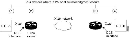
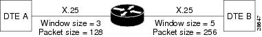
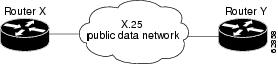
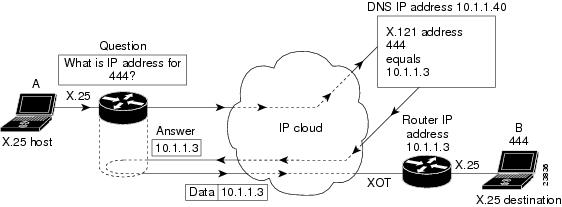
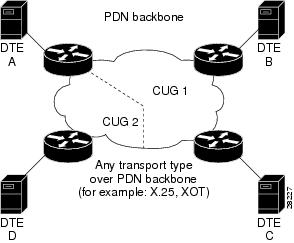

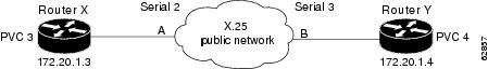
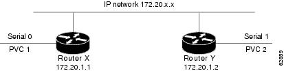
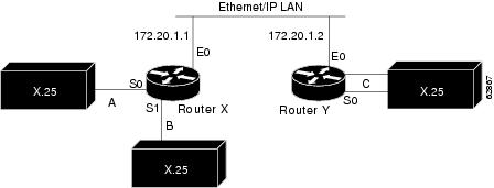

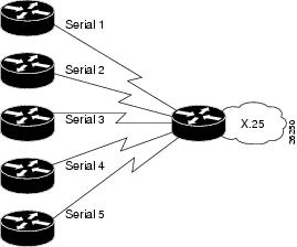
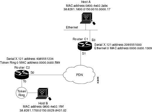
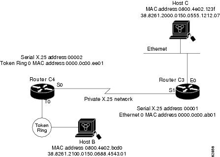
 Feedback