VPDN Technology Overview
Virtual private dial-up networks (VPDNs) securely carry private data over a public network, allowing remote users to access a private network over a shared infrastructure such as the Internet. VPDNs maintain the same security and management policies as a private network, while providing a cost-effective method for point-to-point connections between remote users and a central network.
Information About VPDNs
- Overview of VPDN Technology
- VPDN Terminology
- VPDN Architectures
- VPDN Tunneling Protocols
- VPDN Group Configuration Modes
Overview of VPDN Technology
VPDNs extend private network dial-in services to remote users. VPDNs use Layer 2 tunneling technologies to create virtual point-to-point connections between remote clients and a private network. VPDNs maintain the same security and management policies as a private network, while providing a cost-effective method for point-to-point connections between remote users and a central network.
Instead of connecting directly to the remote private network, VPDN users connect to a nearby access server, which is often located at an Internet service provider (ISP) local point of presence (POP). Data is securely forwarded from the access server to the private network over the Internet, providing a cost-effective method of communication between remote clients and the private network.
A benefit of VPDNs is the way they delegate responsibilities for the network. The customer can outsource responsibility for the information technology (IT) infrastructure to an ISP that maintains the modems that the remote users dial in to, the access servers, and the internetworking expertise. The customer is then responsible only for authenticating users and maintaining the private network.
The figure below shows a basic VPDN network deployment.
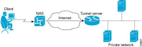
A PPP client dials in to an ISP access server, called the Network Access Server (NAS). The NAS determines whether it should forward that PPP session on to the router or access server that serves as the point of contact for the private network, the tunnel server. The tunnel server authenticates the user and initiates PPP negotiations. Once PPP setup is complete, all frames that are sent between the client and the tunnel server pass through the NAS.
VPDNs can use these tunneling protocols to tunnel link-level frames:
- Layer 2 Tunneling Protocol (L2TP)
- Layer 2 Tunneling Protocol Version 3 (L2TPv3)
- Layer 2 Forwarding (L2F)
- Point-to-Point Tunneling Protocol (PPTP)
Using one of these protocols, a tunnel is established between the NAS or client and the tunnel server, providing secure data transport over a shared infrastructure such as the Internet.
 Note |
VPDNs on the Cisco ASR 1000 Series Aggregation Services Routers can use only the Layer 2 Tunneling Protocol (L2TP) or the Layer 2 Tunneling Protocol Version 3 (L2TPv3) to tunnel link-level frames. |
VPDN Terminology
VPDN Hardware Devices
Generally three devices are involved in VPDN tunneling. Two of these devices function as tunnel endpoints--one device initiates the VPDN tunnel, and the other device terminates the VPDN tunnel. Depending on the tunneling architecture, different types of devices can act as the local tunnel endpoint.
As new tunneling protocols have been developed for VPDNs, protocol-specific terminology has been created to describe some of the devices that participate in VPDN tunneling. However, these devices perform the same basic functions no matter what tunneling protocol is being used. For the sake of clarity we will use this generic terminology to refer to VPDN devices throughout this documentation:
- Client--The client device can be the PC of a dial-in user, or a router attached to a local network. In client-initiated VPDN tunneling scenarios, the client device acts as a tunnel endpoint.
- NAS--The network access server (NAS) is typically a device maintained by an ISP that provides VPDN services for its customers. The NAS is the local point of contact for the client device. Establishing a connection between the NAS and the client will be referred to as “receiving a call” or “placing a call,” depending on whether a dial-in or dial-out scenario is being discussed.
Note |
The Cisco ASR 1000 Series Aggregation Services Routers support only dial-in. |
Depending on the tunneling architecture, the NAS will function as follows:
-
- For NAS-initiated VPDN tunneling scenarios and dial-out VPDN tunneling scenarios, the NAS functions as a tunnel endpoint. The NAS initiates dial-in VPDN tunnels and terminates dial-out VPDN tunnels.
- For client-initiated VPDN tunneling scenarios, the NAS does not function as a a tunnel endpoint; it simply provides Internet connectivity.
- Tunnel server--The tunnel server is typically maintained by the customer and is the contact point for the remote private network. The tunnel server terminates dial-in VPDN tunnels and initiates dial-out VPDN tunnels.
- Tunnel switch--A tunnel switch is a device configured to perform multihop VPDN tunneling. A tunnel switch acts as both a NAS and a tunnel server. The tunnel switch terminates incoming VPDN tunnels and initiates the outgoing VPDN tunnels that will carry data on to the next hop.
Although technically a tunnel switch is a tunnel endpoint for both the incoming tunnel and the outgoing tunnel, for the sake of simplicity the tunnel endpoints in a multihop deployment are considered to be the device that initiates the first tunnel and the device that terminates the final tunnel of the multihop path.
Note |
The Cisco ASR 1000 Series Aggregation Services Routers support only L2TP. |
The table below lists the generic terms and the corresponding technology-specific terms that are sometimes used to describe the NAS and the tunnel server.
| Generic Term |
L2F Term |
L2TP Term |
PPTP Term |
|---|---|---|---|
| NAS |
NAS |
L2TP access concentrator (LAC) |
PPTP access concentrator (PAC) |
| Tunnel server |
Home gateway |
L2TP network server (LNS) |
PPTP network server (PNS) |
VPDN Tunnels
A VPDN tunnel exists between the two tunnel endpoints. The tunnel consists of a control connection and zero or more Layer 2 sessions. The tunnel carries encapsulated PPP datagrams and control messages between the tunnel endpoints. Multiple VPDN sessions can use the same VPDN tunnel.
VPDN Sessions
A VPDN session is created between the tunnel endpoints when an end-to-end PPP connection is established between a client and the tunnel server. Datagrams related to the PPP connection are sent over the tunnel. There is a one-to-one relationship between an established session and the associated call. Multiple VPDN sessions can use the same VPDN tunnel.
VPDN Architectures
- Client-Initiated Dial-In VPDN Tunneling
- NAS-Initiated Dial-In VPDN Tunneling
- Dial-Out VPDN Tunneling
- Multihop VPDN Tunneling
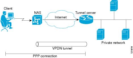
Client-Initiated Dial-In VPDN Tunneling
Client-initiated dial-in VPDN tunneling is also known as voluntary tunneling. In a client-initiated dial-in VPDN tunneling scenario, the client device initiates a Layer 2 tunnel to the tunnel server, and the NAS does not participate in tunnel negotiation or establishment. In this scenario, the NAS is not a tunnel endpoint; it simply provides Internet connectivity. The client device must be configured to initiate the tunnel.
The main advantage of client-initiated VPDN tunneling is that it secures the connection between the client and the ISP NAS. However, client-initiated VPDNs are not as scalable and are more complex than NAS-initiated VPDNs.
Client-initiated VPDN tunneling can use the L2TP protocol or the L2TPv3 protocol if the client device is a router. If the client device is a PC, only the PPTP protocol is supported.
The figure below shows a client-initiated VPDN tunneling scenario.
For further information about client-initiated tunneling deployments, see the “Configuring Client-Initiated Dial-In VPDN Tunneling” module.
Before configuring a client-initiated dial-in VPDN tunneling deployment, you must complete the required tasks in the “Configuring AAA for VPDNs” module.
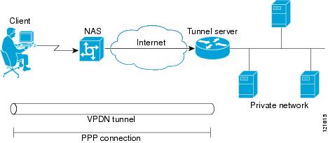
NAS-Initiated Dial-In VPDN Tunneling
NAS-initiated dial-in VPDN tunneling is also known as compulsory tunneling. In a NAS-initiated dial-in VPDN tunneling scenario, the client dials in to the NAS through a medium that supports PPP. If the connection from the client to the ISP NAS is over a medium that is considered secure, such as digital subscriber line (DSL), ISDN, or the public switched telephone network (PSTN), the client can choose not to provide additional security. The PPP session is securely tunneled from the NAS to the tunnel server without any special knowledge or interaction required from the client.
NAS-initiated VPDN tunneling can be configured with the L2TP or L2F protocol.
Note |
The Cisco ASR 1000 Series Aggregation Services Routers support only L2TP. |
The figure below shows a NAS-initiated dial-in tunneling scenario.
For further information about NAS-initiated tunneling deployments, see the Configuring NAS-Initiated Dial-In VPDN Tunneling module.
Before configuring a NAS-initiated dial-in VPDN tunneling deployment, you must complete the required tasks in the Configuring AAA for VPDNs module.
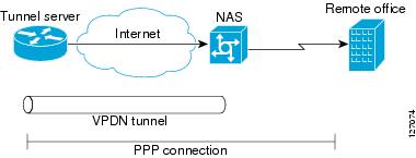
Dial-Out VPDN Tunneling
Dial-out VPDN deployments allow the tunnel server to tunnel outbound calls to the NAS. Dial-out VPDNs allow a centralized network to efficiently and inexpensively establish virtual point-to-point connections with any number of remote offices.
Dial-out VPDN tunneling can be configured only with the L2TP protocol.
Note |
Cisco routers can carry both dial-in and dial-out calls in the same L2TP tunnel. |
A dial-out VPDN tunneling scenario is shown in the figure below.
For further information about dial-out VPDN tunneling deployments, see the Configuring Additional VPDN Features module.
Before configuring a dial-out VPDN tunneling deployment, you must complete the required tasks in the Configuring AAA for VPDNs module.
Multihop VPDN Tunneling
Multihop VPDN is a specialized VPDN configuration that allows packets to pass through multiple tunnels. Ordinarily, packets are not allowed to pass through more than one tunnel. In a multihop tunneling deployment, the VPDN tunnel is terminated after each hop and a new tunnel is initiated to the next hop destination. A maximum of four hops is supported.
Multihop VPDN is required for the scenarios described in these sections:
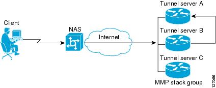
VPDN Tunneling to an MMP Stack Group
Multihop VPDN is required when the private network uses Mutlichassis Multilink PPP (MMP) with multiple tunnel servers in a stack group. Stack group configurations require the ability to establish Layer 2 tunnels between participating hardware devices. If the incoming data is delivered to the stack group over a VPDN tunnel, multihop VPDN is required for the stack group to function.
Multihop VPDN tunneling with MMP can be configured using the L2TP or L2F protocol.
Note |
The Cisco ASR 1000 Aggregation Services Routers support only L2TP. |
The figure below shows a network scenario using a multihop VPDN with an MMP deployment.
For further information about configuring multihop VPDN for MMP deployments, see the Configuring Multihop VPDN module.
Before configuring a multihop VPDN for MMP deployment, you must configure MMP and you must complete the required tasks in the Configuring AAA for VPDNs module.
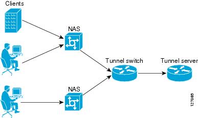
Tunnel Switching VPDNs
Multihop VPDN can be used to configure a router as a tunnel switch. A tunnel switch is a device that is configured as both a NAS and a tunnel server. A tunnel switch is able to receive packets from an incoming VPDN tunnel and send them out over an outgoing VPDN tunnel. Tunnel switch configurations can be used between ISPs to provide wholesale VPDN services.
Multihop tunnel switching can be configured using the L2TP, L2F, or PPTP protocol.
Note |
The Cisco ASR 1000 Aggregation Services Routers support only L2TP. |
The figure below shows a network scenario using a tunnel switching deployment.
For further information about multihop tunnel switching deployments, see the Configuring Multihop VPDN module.
Before configuring a multihop tunnel switching deployment, you must complete the required tasks in the Configuring AAA for VPDNs module.
VPDN Tunneling Protocols
VPDNs use Layer 2 protocols to tunnel the link layer of high-level protocols (for example, PPP frames or asynchronous High-Level Data Link Control (HDLC). ISPs configure their NAS to receive calls from users and to forward the calls to the customer tunnel server.
Usually, the ISP maintains only information about the customer tunnel server. The customer maintains the users’ IP addresses, routing, and other user database functions. Administration between the ISP and the tunnel server is reduced to IP connectivity.
This section contains information on these Layer 2 protocols that can be used for VPDN tunneling:
Note |
Effective with Cisco Release 12.4(11)T, the L2F protocol is not available in Cisco IOS software. |
L2TP
L2TP is an Internet Engineering Task Force (IETF) standard that combines the best features of the two older tunneling protocols: Cisco L2F and Microsoft PPTP.
L2TP offers the same full-range spectrum of features as L2F, but offers additional functionality. An L2TP-capable tunnel server will work with an existing L2F NAS and will concurrently support upgraded components running L2TP. Tunnel servers do not require reconfiguration each time an individual NAS is upgraded from L2F to L2TP. The table below compares L2F and L2TP feature components.
Traditional dialup networking services support only registered IP addresses, which limits the types of applications that are implemented over VPDNs. L2TP supports multiple protocols and unregistered and privately administered IP addresses. This allows the existing access infrastructure--such as the Internet, modems, access servers, and ISDN terminal adapters (TAs)--to be used. It also allows customers to outsource dial-out support, thus reducing overhead for hardware maintenance costs and 800 number fees, and allows them to concentrate corporate gateway resources.
The figure below shows the basic L2TP architecture in a typical dial-in environment.
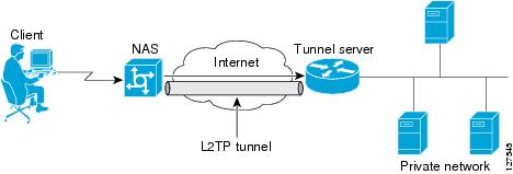
Using L2TP tunneling, an ISP or other access service can create a virtual tunnel to link remote sites or remote users with corporate home networks. The NAS located at the POP of the ISP exchanges PPP messages with remote users and communicates by way of L2TP requests and responses with the private network tunnel server to set up tunnels. L2TP passes protocol-level packets through the virtual tunnel between endpoints of a point-to-point connection. Frames from remote users are accepted by the ISP NAS, stripped of any linked framing or transparency bytes, encapsulated in L2TP, and forwarded over the appropriate tunnel. The private network tunnel server accepts these L2TP frames, strips the L2TP encapsulation, and processes the incoming frames for the appropriate interface.
The figure below depicts the events that occur during establishment of a NAS-initiated dial-in L2TP connection.
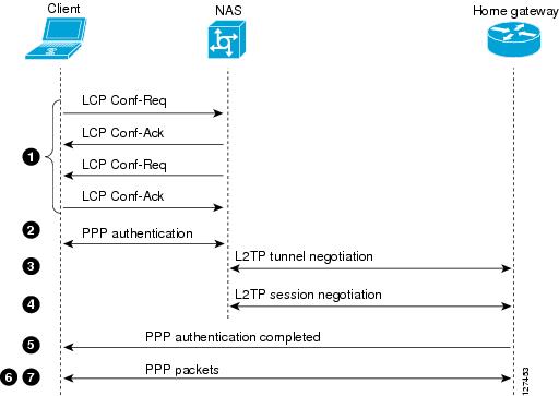
The following describes the sequence of events shown in the figure above and is keyed to the figure:
- The remote user initiates a PPP connection to the ISP NAS using a medium that supports PPP such as the analog telephone system. The NAS accepts the connection, the PPP link is established, and Link Control Protocol (LCP) is negotiated.
- After the end user and NAS negotiate LCP, the NAS partially authenticates the end user with CHAP or PAP. The username, domain name, or Dialed Number Information Service (DNIS) is used to determine whether the user is a VPDN client. If the user is not a VPDN client, authentication continues, and the client will access the Internet or other contacted service. If the username is a VPDN client, the mapping will name a specific endpoint (the tunnel server).
- The tunnel endpoints, the NAS and the tunnel server, authenticate each other before any tunnel or session establishment is attempted. Alternatively, the tunnel server can accept tunnel creation without any tunnel authentication of the NAS. The NAS and the tunnel server exchange control messages to negotiate tunnel establishment.
- Once the tunnel exists, an L2TP session is created for the end user. The NAS and the tunnel server exchange call messages to negotiate session establishment.
- The NAS will propagate the negotiated LCP options and the partially authenticated CHAP or PAP information to the tunnel server. The tunnel server will funnel the negotiated options and authentication information directly to the virtual access interface, allowing authentication to be completed. If the options configured in the virtual template interface do not match the options negotiated with the NAS, the connection will fail and a disconnect notification will be sent to the NAS.
- PPP packets are exchanged between the dial-in client and the remote tunnel server as if no intermediary device (the NAS) is involved.
Subsequent PPP incoming sessions (designated for the same tunnel server) do not repeat the L2TP tunnel negotiation because the L2TP tunnel is already open.
L2TPv3
L2TPv3 is an enhanced version of L2TP with the capability to tunnel any Layer 2 payload. L2TPv3 defines the L2TP protocol for tunneling Layer 2 payloads over an IP core network using Layer 2 Virtual Private Networks (VPNs).
In VPDN deployments, L2TPv3 can be used to establish a client-initiated tunnel from a local router to the remote customer network over an emulated circuit known as a pseudowire. There is one pseudowire associated with each L2TPv3 session.
Rather than using a VPDN group configuration, L2TPv3 uses an L2TP class configuration that is associated with the pseudowire. L2TPv3 pseudowires can also be used to establish L2TP tunnels by configuring an L2TP class on the local device and an accept-dialin VPDN group on the customer network.
For detailed information about the L2TPv3 protocol, see the Additional References section.
L2F
L2F is an older tunneling protocol, but still offers a wide range of useful features. L2F offers a comparison of L2F and L2TP feature components.
Note |
Effective with Cisco Release 12.4(11)T, the L2F protocol is not available in Cisco IOS software. |
The figure below shows the basic L2F architecture in a typical dial-in environment.

Using L2F tunneling, an ISP or other access service can create a virtual tunnel to link remote sites or remote users with the corporate home network. The NAS located at the POP of the ISP exchanges PPP messages with remote users and communicates by way of L2F requests and responses with the private network tunnel server to set up tunnels. L2F passes protocol-level packets through the virtual tunnel between endpoints of a point-to-point connection. Frames from remote users are accepted by the ISP NAS, stripped of any linked framing or transparency bytes, encapsulated in L2F, and forwarded over the appropriate tunnel. The private network tunnel server accepts these L2F frames, strips the L2F encapsulation, and processes the incoming frames for the appropriate interface.
The figure below depicts the events that occur during establishment of a NAS-initiated dial-in L2F connection.
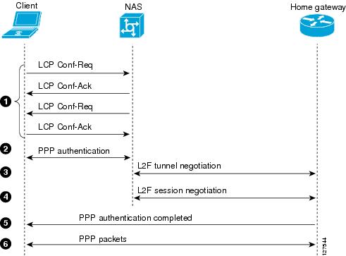
The following describes the sequence of events shown in the figure above and is keyed to the figure:
- The remote user initiates a PPP connection to the ISP NAS using a medium that supports PPP such as the analog telephone system. The NAS accepts the connection, the PPP link is established, and LCP is negotiated.
- The NAS begins PPP authentication by sending a CHAP challenge to the client. The client replies with a CHAP response.
- When the NAS receives the CHAP response, either the phone number from which the user dialed in (when using DNIS-based authentication) or the user domain name (when using authentication based on domain name) matches a configuration on either the NAS or its authentication, authorization, and accounting (AAA) server. The NAS and the tunnel server exchange L2F control packets, opening the L2F tunnel.
- Once the L2F tunnel is open, the NAS and tunnel server exchange L2F session packets. The NAS sends the tunnel server client information from the LCP negotiation, the CHAP challenge, and the CHAP response. The tunnel server creates a virtual access interface for the client and responds to the NAS, opening the L2F session.
- The tunnel server authenticates the CHAP challenge and response (using either local or remote AAA) and sends a CHAP Auth-OK packet to the client. This completes the three-way CHAP authentication.
- When the client receives the CHAP Auth-OK packet, it can send PPP encapsulated packets to the tunnel server. The client and the tunnel server can now exchange PPP encapsulated packets. The NAS acts as a transparent PPP frame forwarder.
Subsequent PPP incoming sessions (designated for the same tunnel server) do not repeat the L2F tunnel negotiation because the L2F tunnel is already open.
PPTP
PPTP is a network protocol that enables the secure transfer of data from a remote client to a private enterprise server by creating a VPDN across TCP/IP-based data networks. PPTP supports on-demand, multiprotocol, virtual private networking over public networks, such as the Internet.
Cisco supports only client-initiated VPDNs using PPTP. Only the client and the tunnel server need to be configured for VPDN. The client first establishes basic connectivity by dialing in to an ISP NAS. Once the PPP session has been established, the client initiates a PPTP tunnel to the tunnel server.
Microsoft Point-to-Point Encryption (MPPE), an encryption technology developed by Microsoft to encrypt point-to-point links, can be used to encrypt PPTP VPDNs. It encrypts the entire session from the client to the tunnel server.
The following describes the protocol negotiation events that establish a client-initiated PPTP tunnel:
- The client dials in to the ISP NAS and establishes a PPP session.
- The client establishes a TCP connection with the tunnel server.
- The tunnel server accepts the TCP connection.
- The client sends a PPTP Start Control Connection Request (SCCRQ) message to the tunnel server.
- The tunnel server establishes a new PPTP tunnel and replies with a Start Control Connection Reply (SCCRP) message.
- The client initiates the session by sending an Outgoing Call Request (OCRQ) message to the tunnel server.
- The tunnel server creates a virtual access interface.
- The tunnel server replies with an Outgoing Call Reply (OCRP) message.
VPDN Group Configuration Modes
Many VPDN configuration tasks are performed within a VPDN group. A VPDN group can be configured to function either as a NAS VPDN group or as a tunnel server VPDN group, but not as both. However, an individual router can be configured with both a NAS VPDN group and a tunnel server VPDN group.
You can configure a VPDN group as a specific type of VPDN group by issuing at least one of the commands listed in the table below:
- Tunnel server VPDN groups can be configured to accept dial-in calls, request dial-out calls, or both.
- NAS VPDN groups can be configured to request dial-in calls, accept dial-out calls, or both.
| VPDN Group Type |
Command |
Command Mode |
Command Mode Prompt |
|---|---|---|---|
| tunnel server |
accept-dialin |
VPDN accept-dialin configuration |
Router(config-vpdn-acc-in)# |
| tunnel server |
request-dialout |
VPDN request-dialout configuration |
Router(config-vpdn-req-ou)# |
| NAS |
request-dialin |
VPDN request-dialin configuration |
Router(config-vpdn-req-in)# |
| NAS |
accept-dialout |
VPDN accept-dialout configuration |
Router(config-vpdn-acc-ou)# |
Many of the commands required to properly configure VPDN tunneling are issued in one of the VPDN subgroup configuration modes shown in the table above. Removing the VPDN subgroup command configuration will remove all subordinate VPDN subgroup configuration commands as well.
Where to Go Next
Once you have identified the VPDN architecture that you want to configure and the tunneling protocol that you will use, you should perform the required tasks in the Configuring AAA for VPDNs module.
Additional References
Related Documents
| Related Topic |
Document Title |
|---|---|
| Cisco IOS commands |
|
| VPDN commands |
Cisco IOS VPDN Command Reference |
| Information about Multichassis Multilink PPP |
Implementing Multichassis Multilink PPP module |
| Technical support documentation for L2TP |
Layer 2 Tunnel Protocol (L2TP) |
| Technical support documentation for PPTP |
Point to Point Tunneling Protocol (PPTP) |
| Technical support documentation for VPDNs |
Virtual Private Dial-Up Network (VPDN) |
| Dial Technologies commands: complete command syntax, command mode, defaults, usage guidelines, and examples |
Cisco IOS Dial Technologies Command Reference |
| Information on L2TPv3 |
L2TPv3: Layer 2 Tunnel Protocol Version 3 module |
Standards
| Standard |
Title |
|---|---|
| None |
-- |
MIBs
| MIB |
MIBs Link |
|---|---|
| To locate and download MIBs for selected platforms, Cisco IOS releases, and feature sets, use Cisco MIB Locator found at the following URL: |
RFCs
| RFC |
Title |
|---|---|
| RFC 2341 |
Cisco Layer Two Forwarding (Protocol) L2F |
| RFC 2637 |
Point-to-Point Tunneling Protocol (PPTP) |
| RFC 2661 |
Layer Two Tunneling Protocol L2TP |
| RFC 3931 |
Layer Two Tunneling Protocol - Version 3 (L2TPv3) |
Technical Assistance
| Description |
Link |
|---|---|
| The Cisco Support and Documentation website provides online resources to download documentation, software, and tools. Use these resources to install and configure the software and to troubleshoot and resolve technical issues with Cisco products and technologies. Access to most tools on the Cisco Support and Documentation website requires a Cisco.com user ID and password. |
 Feedback