VPDN Configuration Guide, Cisco IOS Release 12.2SR
Bias-Free Language
The documentation set for this product strives to use bias-free language. For the purposes of this documentation set, bias-free is defined as language that does not imply discrimination based on age, disability, gender, racial identity, ethnic identity, sexual orientation, socioeconomic status, and intersectionality. Exceptions may be present in the documentation due to language that is hardcoded in the user interfaces of the product software, language used based on RFP documentation, or language that is used by a referenced third-party product. Learn more about how Cisco is using Inclusive Language.
- Updated:
- April 4, 2011
Chapter: Configuring NAS-Initiated Dial-In VPDN Tunneling
- Finding Feature Information
- Prerequisites for Configuring NAS-Initiated Dial-In VPDN Tunneling
- Information About NAS-Initiated Dial-In VPDN Tunneling
- How to Configure NAS-Initiated Dial-In VPDN Tunneling
Configuring NAS-Initiated Dial-In VPDN Tunneling
Network access server (NAS)-initiated dial-in tunneling provides secure tunneling of a PPP session from a NAS to a tunnel server without any special knowledge or interaction required from the client.
- Finding Feature Information
- Prerequisites for Configuring NAS-Initiated Dial-In VPDN Tunneling
- Information About NAS-Initiated Dial-In VPDN Tunneling
- How to Configure NAS-Initiated Dial-In VPDN Tunneling
- Configuration Examples for NAS-Initiated Dial-In VPDN Tunneling
- Where to Go Next
- Additional References
- Feature Information for NAS-Initiated Dial-In VPDN Tunneling
Finding Feature Information
Your software release may not support all the features documented in this module. For the latest feature information and caveats, see the release notes for your platform and software release. To find information about the features documented in this module, and to see a list of the releases in which each feature is supported, see the Feature Information Table at the end of this document.
Use Cisco Feature Navigator to find information about platform support and Cisco software image support. To access Cisco Feature Navigator, go to www.cisco.com/go/cfn. An account on Cisco.com is not required.
Prerequisites for Configuring NAS-Initiated Dial-In VPDN Tunneling
- Before performing the tasks documented in this module, you must perform the required tasks in the Configuring AAA for VPDNs module.
- The NAS should be configured to receive incoming calls from clients using ISDN, the Public Switched Telephone Network (PSTN), Digital Subscriber Line (DSL), or cable modem .
Information About NAS-Initiated Dial-In VPDN Tunneling
NAS-Initiated Dial-in VPDN Tunneling
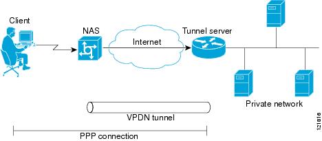
NAS-initiated dial-in VPDN tunneling is also known as compulsory tunneling. In NAS-initiated dial-in VPDN tunneling, the client dials in to the NAS through a medium that supports PPP. If the connection from the client to the Internet service provider (ISP) NAS is over a medium that is considered secure, such as DSL, ISDN, or the PSTN, the client might choose not to provide additional security. The PPP session is securely tunneled from the NAS to the tunnel server without any special knowledge or interaction required from the client. NAS-initiated dial-in VPDN tunnels can use either the Layer 2 Tunneling Protocol (L2TP) or the Layer 2 Forwarding (L2F) protocol.
 Note |
The Cisco ASR 1000 Series Aggregation Services Routers support only L2TP. |
A NAS-initiated dial-in tunneling scenario is shown in the figure below.
L2TP Calling Station ID Suppression
In a NAS-initiated dial-in L2TP tunneling scenario, when the NAS connects to a tunnel server it transfers numerous attribute-value (AV) pairs as part of the session setup process. One of these AV pairs is L2TP AV pair 22, the Calling Number ID. The Calling Number ID AV pair includes the calling station ID of the originator of the session, which can be the phone number of the originator, the Logical Line ID (LLID) used to make the connection on the LAC, or the MAC address of the PC connecting to the network. This information can be considered sensitive in cases where the NAS and tunnel server are being managed by different entities. Depending on the security requirements of the NAS or end users, it might be desirable for the NAS to suppress part or all of the calling station ID.
Parts of the calling station ID can be masked, or the calling station ID can be removed completely. Calling station ID suppression can be configured globally on the NAS, for individual VPDN groups on the NAS, or on the remote RADIUS server if one is configured.
L2TP Failover
If a NAS fails to contact its peer during L2TP tunnel establishment, it can fail over to another configured tunnel server and attempt tunnel establishment with that device.
Failover can occur in these scenarios:
- If the router sends a Start Control Connection Request (SCCRQ) a number of times and receives no response from the peer
- If the router receives a Stop Control Connection Notification (StopCCN) from its peer
- If the router receives a Call Disconnect Notify (CDN) message from its peer
In both the StopCCN control message and the CDN control message, a Result Code AV pair is included, which indicates the reason for tunnel or session termination, respectively. This AV pair might also include an optional Error Code, which further describes the nature of the termination. The various Result Code and Error Code values have been standardized in RFC 2661. Failover will occur if the combination of Result Code and Error Code values as defined in the table below is received from the peer.
| Control Message |
Result Code |
Error Code |
|---|---|---|
| StopCCN, CDN |
2: General error, see Error Code. |
4: Insufficient resources to handle this operation now. 6: A generic vendor-specific error occurred.1 7: Try another. 9: Try another directed. |
| CDN |
4: Temporary lack of resources. |
-- |
When one of the three scenarios occurs, the router marks the peer IP address as busy for 60 seconds by default. During that time no attempt is made to establish a session or tunnel with the peer. The router selects an alternate peer to contact if one is configured. If a tunnel already exists to the alternate peer, new sessions are brought up in the existing tunnel. Otherwise, the router begins negotiations to establish a tunnel to the alternate peer.
How to Configure NAS-Initiated Dial-In VPDN Tunneling
- Configuring the NAS to Request Dial-In VPDN Tunnels
- Configuring the Tunnel Server to Accept Dial-In VPDN Tunnels
- Configuring the Virtual Template on the Tunnel Server
- Verifying a NAS-Initiated VPDN Configuration
- Configuring L2TP Calling Station ID Suppression
Configuring the NAS to Request Dial-In VPDN Tunnels
The NAS must be configured to request tunnel establishment with the remote tunnel server. Perform this task on the NAS to configure a VPDN request dial-in subgroup and the IP address of the tunnel server that will be the other endpoint of the VPDN tunnel.
DETAILED STEPS
What to Do Next
You must perform the task in the Configuring the Tunnel Server to Accept Dial-In VPDN Tunnels.
Configuring the Tunnel Server to Accept Dial-In VPDN Tunnels
The tunnel server must be configured to accept tunnel requests from the remote NAS. Perform this task on the tunnel server to create a VPDN accept dial-in subgroup and to configure the tunnel server to accept tunnels from the NAS that will be the other endpoint of the VPDN tunnel. To configure the tunnel server to accept tunnels from multiple NASs, you must perform this task for each NAS.
DETAILED STEPS
| Command or Action | Purpose | |||
|---|---|---|---|---|
| Step 1 | enable Example: Router> enable |
Enables privileged EXEC mode.
|
||
| Step 2 | configure terminal Example: Router# configure terminal |
Enters global configuration mode. |
||
| Step 3 | vpdn-group name Example: Router(config)# vpdn-group 1 |
Creates a VPDN group and enters VPDN group configuration mode. |
||
| Step 4 | description string Example: Router(config-vpdn)# description myvpdngroup |
(Optional) Adds a description to a VPDN group. |
||
| Step 5 | accept-dialin Example: Router(config-vpdn)# accept-dialin |
Configures a tunnel server to accept requests from a NAS to establish an L2F or L2TP tunnel, creates an accept-dialin VPDN subgroup, and enters VPDN accept dial-in subgroup configuration mode. |
||
| Step 6 | protocol {any | l2f | l2tp} Example: Router(config-vpdn-acc-in)# protocol l2tp |
Specifies the Layer 2 protocol that the VPDN group will use.
|
||
| Step 7 | virtual-template number Example: Router(config-vpdn-acc-in)# virtual-template 1 |
Specifies which virtual template will be used to clone virtual access interfaces. |
||
| Step 8 | exit Example: Router(config-vpdn-acc-in)# exit |
Exits to VPDN group configuration mode. |
||
| Step 9 | terminate-from hostname host-name Example: Router(config-vpdn)# terminate-from hostname NAS12 |
Specifies the hostname of the remote NAS that will be required when accepting a VPDN tunnel. |
||
| Step 10 | lcp renegotiation {always | on-mismatch} Example: Router(config-vpdn)# lcp renegotiation always |
(Optional) Allows the tunnel server to renegotiate the PPP Link Control Protocol (LCP) on dial-in calls using L2TP or L2F.
|
||
| Step 11 | force-local-chap Example: Router(config-vpdn)# force-local-chap |
(Optional) Forces the tunnel server to reauthenticate the client.
|
What to Do Next
You must perform the task in the Configuring the Virtual Template on the Tunnel Server.
Configuring the Virtual Template on the Tunnel Server
When a request to establish a tunnel is received by the tunnel server, the tunnel server must create a virtual access interface. The virtual access interface is cloned from a virtual template interface, used, and then freed when no longer needed. The virtual template interface is a logical entity that is not tied to any physical interface.
Perform this task on the tunnel server to configure a basic virtual template .
DETAILED STEPS
| Command or Action | Purpose | |||
|---|---|---|---|---|
| Step 1 | enable Example: Router> enable |
Enables privileged EXEC mode. |
||
| Step 2 | configure terminal Example: Router# configure terminal |
Enters global configuration mode. |
||
| Step 3 | interface virtual-template number Example: Router(config)# interface virtual-template 1 |
Enters interface configuration mode and creates a virtual template interface that can be configured and applied dynamically in creating virtual access interfaces. |
||
| Step 4 | ip unnumbered type number Example: Router(config-if)# ip unnumbered FastEthernet 0/0 |
Enables IP processing on a serial interface without assigning an explicit IP address to the interface.
|
||
| Step 5 | ppp authentication protocol1 [protocol2...] [if-needed] [list-name | default] [callin] [one-time] [optional] Example: Router(config-if)# ppp authentication chap |
Enables at least one PPP authentication protocol and specifies the order in which the protocols are selected on the interface. |
||
| Step 6 | peer default ip address {ip-address| dhcp-pool | dhcp | pool [pool-name]} Example: Router(config-if)# peer default ip address pool mypool |
Specifies an IP address, an address from a specific IP address pool, or an address from the Dynamic Host Configuration Protocol (DHCP) mechanism to be returned to a remote peer connecting to this interface. |
||
| Step 7 | encapsulation encapsulation-type Example: Router(config-if)# encapsulation ppp |
Sets the encapsulation method used by the interface. |
Verifying a NAS-Initiated VPDN Configuration
- Verifying and Troubleshooting Tunnel Establishment Between the NAS and the Tunnel Server
- Verifying the Connection Between the Client and the NAS
Verifying and Troubleshooting Tunnel Establishment Between the NAS and the Tunnel Server
Perform this task to verify that a tunnel between the NAS and the tunnel server has been established, and to troubleshoot problems with tunnel establishment.
DETAILED STEPS
| Step 1 |
enable Enter this command to enable privileged EXEC mode. Enter your password if prompted: Example: Router> enable |
| Step 2 |
show vpdn tunnel all Enter this command to display details about all active VPDN tunnels. This example shows output from a tunnel server with a single active L2F tunnel: Example: Router# show vpdn tunnel all % No active L2TP tunnels L2F Tunnel NAS name: ISP-NAS NAS CLID: 36 NAS IP address 172.22.66.23 Gateway name: ENT-TS Gateway CLID: 1 Gateway IP address 172.22.66.25 State: open Packets out: 52 Bytes out: 1799 Packets in: 100 Bytes in: 7143 If no active tunnels have been established with the NAS, proceed with the following steps to troubleshoot the problem.
|
| Step 3 |
ping ip-address Enter this command to ping the NAS. The following output shows the result of a successful ping from the tunnel server to the NAS: Example: Router# ping 172.22.66.25 Type escape sequence to abort. Sending 5, 100-byte ICMP Echos to 172.30.2.1, timeout is 2 seconds: !!!!! Success rate is 100 percent (5/5), round-trip min/avg/max = 128/132/152 ms If the tunnel server is unable to ping the NAS, there might be a problem with the routing path between the devices, or the NAS might not be functional. |
| Step 4 |
debug vpdn event Enter this command to display the VPDN events that occur during tunnel establishment . The following output from the tunnel server shows normal VPDN tunnel establishment for an L2F tunnel: Example: Router# debug vpdn event L2F: Chap authentication succeeded for nas1. Virtual-Access3 VPN Virtual interface created for user6@cisco.com Virtual-Access3 VPN Set to Async interface Virtual-Access3 VPN Clone from Vtemplate 1 block=1 filterPPP=0 %LINK-3-UPDOWN: Interface Virtual-Access3, changed state to up Virtual-Access3 VPN Bind interface direction=2 Virtual-Access3 VPN PPP LCP accepted sent & rcv CONFACK %LINEPROTO-5-UPDOWN: Line protocol on Interface Virtual-Access3, changed state to up The following output from the tunnel server shows normal VPDN tunnel establishment for an L2TP tunnel: Example: Router# debug vpdn event 20:19:17: L2TP: I SCCRQ from ts1 tnl 8 20:19:17: L2X: Never heard of ts1 20:19:17: Tnl 7 L2TP: New tunnel created for remote ts1, address 172.21.9.4 20:19:17: Tnl 7 L2TP: Got a challenge in SCCRQ, ts1 20:19:17: Tnl 7 L2TP: Tunnel state change from idle to wait-ctl-reply 20:19:17: Tnl 7 L2TP: Got a Challenge Response in SCCCN from ts1 20:19:17: Tnl 7 L2TP: Tunnel Authentication success 20:19:17: Tnl 7 L2TP: Tunnel state change from wait-ctl-reply to established 20:19:17: Tnl 7 L2TP: SM State established 20:19:17: Tnl/Cl 7/1 L2TP: Session FS enabled 20:19:17: Tnl/Cl 7/1 L2TP: Session state change from idle to wait-for-tunnel 20:19:17: Tnl/Cl 7/1 L2TP: New session created 20:19:17: Tnl/Cl 7/1 L2TP: O ICRP to ts1 8/1 20:19:17: Tnl/Cl 7/1 L2TP: Session state change from wait-for-tunnel to wait-connect 20:19:17: Tnl/Cl 7/1 L2TP: Session state change from wait-connect to established 20:19:17: Vi1 VPDN: Virtual interface created for bum1@cisco.com 20:19:17: Vi1 VPDN: Set to Async interface 20:19:17: Vi1 VPDN: Clone from Vtemplate 1 filterPPP=0 blocking 20:19:18: %LINK-3-UPDOWN: Interface Virtual-Access1, changed state to up 20:19:18: Vi1 VPDN: Bind interface direction=2 20:19:18: Vi1 VPDN: PPP LCP accepting rcv CONFACK 20:19:19: %LINEPROTO-5-UPDOWN: Line protocol on Interface Virtual-Access1, changed state to up |
| Step 5 |
debug vpdn errors Enter this command to display error messages that are generated during tunnel establishment. The following output from the NAS shows an authentication failure during tunnel establishment. Example: Router# debug vpdn errors %LINEPROTO-5-UPDOWN: Line protocol on Interface Async1, changed state to down %LINK-5-CHANGED: Interface Async1, changed state to reset %LINK-3-UPDOWN: Interface Async1, changed state to down %LINK-3-UPDOWN: Interface Async1, changed state to up %LINEPROTO-5-UPDOWN: Line protocol on Interface Async1, changed state to up VPDN tunnel management packet failed to authenticate VPDN tunnel management packet failed to authenticate If an authentication failure occurs, verify that both the NAS and the tunnel server are configured with the same secret password. |
Verifying the Connection Between the Client and the NAS
Perform this task to verify the connection between the dial-in client and the NAS.
DETAILED STEPS
| Step 1 |
Dial in to the NAS from a client PC. Ensure that the client PC is able to connect to the NAS by establishing a dial-in connection. As the call comes into the NAS, a LINK-3-UPDOWN message automatically appears on the NAS terminal screen. In the following example, the call comes into the NAS on asynchronous interface 14: Example: *Jan 1 21:22:18.410: %LINK-3-UPDOWN: Interface Async14, changed state to up
If this message is not displayed by the NAS, there is a problem with the dial-in configuration. |
||
| Step 2 |
enable Enter this command to enable privileged EXEC mode. Enter your password if prompted: Example: Router> enable |
||
| Step 3 |
show caller user user Enter this command on the tunnel server to verify that the client received an IP address. The following example shows that user3 is using IP address 172.30.2.1. Example: Router# show caller user user3@cisco.com User: user3@cisco.com, line Vi1, service PPP L2F, active 00:01:35 PPP: LCP Open, CHAP (<- AAA), IPCP IP: Local 172.22.66.25, remote 172.30.2.1 VPDN: NAS ISP-NAS, MID 1, MID open HGW ENT-TS, NAS CLID 36, HGW CLID 1, tunnel open Counts: 105 packets input, 8979 bytes, 0 no buffer 0 input errors, 0 CRC, 0 frame, 0 overrun 18 packets output, 295 bytes, 0 underruns 0 output errors, 0 collisions, 0 interface resets If an incorrect IP address or no IP address is displayed, there is a problem with IP addresses assignment. Verify the configuration of the peer default ip address command in the virtual template on the tunnel server. |
||
| Step 4 |
show interfaces virtual-access number Enter this command to verify that the interface is up, that LCP is open, and that no errors are reported. The following output shows a functional interface: Example: Router# show interfaces virtual-access 1 Virtual-Access1 is up, line protocol is up Hardware is Virtual Access interface Interface is unnumbered. Using address of FastEthernet0/0 (172.22.66.25) MTU 1500 bytes, BW 115 Kbit, DLY 100000 usec, reliablility 255/255, txload 1/255, rxload 1/255 Encapsulation PPP, loopback not set, keepalive set (10 sec) DTR is pulsed for 5 seconds on reset LCP Open Open: IPCP Last input 00:00:02, output never, output hang never Last clearing of "show interface" counters 3d00h Queueing strategy: fifo Output queue 1/40, 0 drops; input queue 0/75, 0 drops 5 minute input rate 0 bits/sec, 0 packets/sec 5 minute output rate 0 bits/sec, 0 packets/sec 114 packets input, 9563 bytes, 0 no buffer Received 0 broadcasts, 0 runts, 0 giants, 0 throttles 0 input errors, 0 CRC, 0 frame, 0 overrun, 0 ignored, 0 abort 27 packets output, 864 bytes, 0 underruns 0 output errors, 0 collisions, 0 interface resets 0 output buffer failures, 0 output buffers swapped out 0 carrier transitions The virtual access interface is up and the line protocol is up, showing that virtual interface establishment was successful. |
||
| Step 5 |
show vpdn session Enter this command on the tunnel server to verify that there are active VPDN sessions. This example shows output from a tunnel server with several active L2F and L2TP tunnels. Example: Router# show vpdn session L2TP Session Information Total tunnels 1 sessions 4 LocID RemID TunID Intf Username State Last Chg Uniq ID 4 691 13695 Se0/0 nobody2@cisco.com est 00:06:00 4 5 692 13695 SSS Circuit nobody1@cisco.com est 00:01:43 8 6 693 13695 SSS Circuit nobody1@cisco.com est 00:01:43 9 3 690 13695 SSS Circuit nobody3@cisco.com est 2d21h 3 L2F Session Information Total tunnels 1 sessions 2 CLID MID Username Intf State Uniq ID 1 2 nobody@cisco.com SSS Circuit open 10 1 3 nobody@cisco.com SSS Circuit open 11 If there is no session established for the client, you should perform the troubleshooting steps in the Verifying and Troubleshooting Tunnel Establishment Between the NAS and the Tunnel Server. |
Configuring L2TP Calling Station ID Suppression
Calling station ID suppression can be configured globally on the NAS, for individual VPDN groups on the NAS, or on the remote RADIUS server if one is configured.
The order of precedence for L2TP calling station ID suppression configurations is as follows:
- A RADIUS server configuration will take precedence over any configuration on the NAS.
- A VPDN group configuration will take precedence over a global configuration for calls associated with that VPDN group.
- A global configuration will be applied if no other method is configured.
Perform one or more of the following tasks to configure L2TP calling station ID suppression:
- Prerequisites for Configuring L2TP Calling Station ID Suppression
- Configuring Global L2TP Calling Station ID Suppression on the NAS
- Configuring L2TP Calling Station ID Suppression for a VPDN Group on the NAS
- Configuring L2TP Calling Station ID Suppression on the NAS Remote RADIUS Server
Prerequisites for Configuring L2TP Calling Station ID Suppression
- You must configure the NAS and the tunnel server to use the L2TP protocol when performing the tasks in the Configuring the NAS to Request Dial-In VPDN Tunnels section and the Configuring the Tunnel Server to Accept Dial-In VPDN Tunnels section.
- You must configure the NAS to tunnel calls based on the domain name when performing the task in the Configuring the NAS to Request Dial-In VPDN Tunnels section.
- You must configure the VPDN search order to use the domain name when performing the task in the Configuring the VPDN Tunnel Authorization Search Order section of the Configuring AAA for VPDNs module.
Configuring Global L2TP Calling Station ID Suppression on the NAS
The calling station ID information included in L2TP AV pair 22 can be removed or masked for every L2TP session established on the router if you configure L2TP calling station ID suppression globally. This configuration is compatible with either local or remote authorization.
Perform this task on the NAS to configure global L2TP calling station ID suppression.
DETAILED STEPS
| Command or Action | Purpose | |
|---|---|---|
| Step 1 | enable Example: Router> enable |
Enables privileged EXEC mode.
|
| Step 2 | configure terminal Example: Router# configure terminal |
Enters global configuration mode. |
| Step 3 | vpdn l2tp attribute clid mask-method {right mask-character characters | remove} [match match-string] Example: Router(config)# vpdn l2tp attribute clid mask-method right # 6 match %321 |
Configures a NAS to suppress L2TP calling station IDs globally on the router.
|
Configuring L2TP Calling Station ID Suppression for a VPDN Group on the NAS
The calling station ID information included in L2TP AV pair 22 can be removed or masked for calls associated with a specific VPDN group. This configuration is compatible with local authorization configurations.
Perform this task on the NAS to configure L2TP calling station ID suppression for calls associated with a particular VPDN group when using local authorization.
- You must configure the NAS and the tunnel server for local authorization when performing the task in the Configuring AAA on the NAS and the Tunnel Server section of the Configuring AAA for VPDNs module.
DETAILED STEPS
| Command or Action | Purpose | |
|---|---|---|
| Step 1 | enable Example: Router> enable |
Enables privileged EXEC mode. |
| Step 2 | configure terminal Example: Router# configure terminal |
Enters global configuration mode. |
| Step 3 | vpdn-group name Example: Router(config)# vpdn-group L2TP |
Creates a VPDN group and enters VPDN group configuration mode. |
| Step 4 | l2tp attribute clid mask-method {right mask-character characters| remove} [match match-string] Example: Router (config-vpdn)# l2tp attribute clid mask-method remove |
Configures a NAS to suppress L2TP calling station IDs for sessions associated with a VPDN group or VPDN template.
|
Configuring L2TP Calling Station ID Suppression on the NAS Remote RADIUS Server
L2TP calling station ID suppression can be configured directly on the NAS, or in the RADIUS user profile. Configuring L2TP calling station ID suppression in the RADIUS user profile allows the configuration to be propagated to multiple NASs without having to configure each one.
Perform this task on the RADIUS server to configure a user profile that will allow the RADIUS server to instruct NASs to remove or mask the L2TP calling station ID.
- The NAS must be configured for remote RADIUS AAA. Perform the tasks for configuring AAA on the NAS and the tunnel server, and configuring remote AAA for VPDNs as described in the Configuring AAA for VPDNs module.
- The RADIUS server must be configured for AAA.
DETAILED STEPS
| Command or Action | Purpose | |
|---|---|---|
| Step 1 | Cisco-Avpair = vpdn:l2tp-tunnel-password= secret Example: Cisco-Avpair = vpdn:l2tp-tunnel-password=cisco |
Specifies the L2TP tunnel password in the RADIUS user profile. |
| Step 2 | Cisco-Avpair = vpdn:tunnel-type= l2tp Example: Cisco-Avpair = vpdn:tunnel-type=l2tp |
Specifies L2TP as the tunneling protocol in the RADIUS user profile. |
| Step 3 | Cisco-Avpair = vpdn:tunnel-id= name Example: Cisco-Avpair = vpdn:tunnel-id=test |
Specifies the tunnel ID in the RADIUS user profile. |
| Step 4 | Cisco-Avpair = vpdn:ip-address= address Example: Cisco-Avpair = vpdn:ip-address=172.16.9.9 |
Specifies the NAS IP address in the RADIUS user profile. |
| Step 5 | Cisco-Avpair = vpdn:l2tp-clid-mask-method= {right: character : characters | remove} Example: Cisco-Avpair = vpdn:l2tp-clid-mask-method= right:#:5 |
Specifies L2TP calling station ID suppression parameters in the RADIUS user profile. |
Configuration Examples for NAS-Initiated Dial-In VPDN Tunneling
- Example Configuring the NAS for Dial-In VPDNs
- Example Configuring the Tunnel Server for Dial-in VPDNs
- Example L2TP Calling Station ID Suppression with Local Authorization
- Example L2TP Calling Station ID Suppression with RADIUS Authorization
Example Configuring the NAS for Dial-In VPDNs
The following example configures a NAS named ISP-NAS to tunnel PPP calls to a tunnel server named ENT-TS using L2TP and local authentication and authorization:
! Enable AAA authentication and authorization with RADIUS as the default method
aaa new-model
aaa authentication ppp default radius
aaa authorization network default radius
!
! Configure the VPDN tunnel authentication password using the local name
username ISP-NAS password 7 tunnelme
username ENT-TS password 7 tunnelme
!
vpdn enable
!
! Configure VPN to first search on the client domain name and then on the DNIS
vpdn search-order domain dnis
!
! Allow a maximum of 10 simultaneous VPDN sessions
vpdn session-limit 10
!
! Configure the NAS to initiate VPDN dial-in sessions to the tunnel server
vpdn-group 1
 request-dialin
 protocol l2tp
 domain cisco.com
!
 initiate-to ip 172.22.66.25
 local name ISP-NAS
!
! Specifies the RADIUS server IP address, authorization port, and accounting port
radius-server host 172.22.66.16 auth-port 1645 acct-port 1646
!
! Specifies the authentication key to be used with the RADIUS server
radius-server key cisco
!
Example Configuring the Tunnel Server for Dial-in VPDNs
The following example show a tunnel server named ENT-TS configured to accept L2TP tunnels from a NAS named ISP-NAS using local authentication and authorization:
! Configure AAA to first use the local database and then contact the RADIUS server for
! PPP authentication
aaa new-model
aaa authentication ppp default local radius
!
! Configure AAA network authorization and accounting by using the RADIUS server
aaa authorization network default radius
aaa accounting network default start-stop radius
!
! Configure the VPDN tunnel authentication password using the local name
username ISP-NAS password 7 tunnelme
username ENT-TS password 7 tunnelme
!
vpdn enable
!
! Configure the tunnel server to accept dial-in sessions from the NAS
vpdn-group 1
 accept-dialin
 protocol l2tp
 virtual-template 1
!
 terminate-from hostname ISP-NAS
 local name ENT-TS
 force-local-chap
!
! Configure the virtual template
interface Virtual-Template1
  gigabitethernet0/0/0
 ppp authentication chap
 peer default ip address pool default
 encapsulation ppp
!
! Specifies the RADIUS server IP address, authorization port, and accounting port
radius-server host 172.22.66.13 auth-port 1645 acct-port 1646
!
! Specifies the authentication key to be used with the RADIUS server
radius-server key cisco
Example L2TP Calling Station ID Suppression with Local Authorization
The following example configures a NAS for PPP over Gigabit Ethernet over virtual LAN (PPPoEoVLAN). The NAS obtains a calling station ID from LLID NAS port preauthorization through RADIUS. The calling station ID will be removed from AV pair 22 for tunnels associated with the VPDN group named L2TP if the string #184 is included in the username.
hostname LAC
!
enable secret 5 $1$8qtb$MHcYeW2kn8VNYgz932eXl.
enable password lab
!
aaa new-model
!
aaa group server radius LLID-Radius
 server 192.168.1.5 auth-port 1645 acct-port 1646
!
aaa group server radius LAC-Radius
 server 192.168.1.6 auth-port 1645 acct-port 1646
!
aaa authentication ppp default local
aaa authorization network default local
aaa authorization network LLID group LLID-Radius
aaa accounting network default start-stop group LAC-Radius
aaa nas port extended
aaa session-id common
!
ip subnet-zero
ip cef
no ip domain lookup
!
vpdn enable
vpdn search-order domain
!
vpdn-group L2TP
 request-dialin
 protocol l2tp
 domain cisco.com
 domain cisco.com#184
!
 initiate-to ip 192.168.1.4
 local name test
 l2tp tunnel password 0 cisco
 l2tp attribute clid mask-method remove match #184
!
bba-group ppoe 2
 virtual-template 1
 nas-port format d 2/2/4
!
subscriber access pppoe pre-authorize nas-port-id LLID send username
!
interface Loopback0
 no ip address
!
interface Loopback1
 ip address 10.1.1.1 255.255.255.0
!
interface gigabitethernet0/0/0
 ip address 192.168.1.3 255.255.255.0
 no cdp enable
!
interface gigabitethernet0/0/0.20
 encapsulation dot1Q 1024
 no snmp trap link-status
 ppoe enable group 2
 pppoe max-sessions 200
 no cdp enable
!
interface gigabitethernet1/0/0
 ip address 10.1.1.10 255.255.255.0
 no cdp enable
!
interface Serial2/0/0
no ip address
 shutdown
 serial restart-delay 0
!
interface Serial3/0/0
 no ip address
 shutdown
 serial restart-delay 0
!
interface Virtual-Template1
 ip unnumbered gigabitethernet1/0/0
 ip mroute-cache
 no peer default ip address
 ppp authentication pap
!
ip classless
ip route 0.0.0.0 0.0.0.0 gigabitethernet0/0/0
ip route 10.0.0.0 255.0.0.0 gigabitethernet1/0/0
!
no ip http server
!
radius-server attribute 69 clear
radius-server host 192.168.1.5 auth-port 1645 acct-port 1646
radius-server host 192.168.1.6 auth-port 1645 acct-port 1646
radius-server domain-stripping delimiter #
radius-server key cisco
radius-server vsa send accounting
radius-server vsa send authentication
!
control-plane
!
line con 0
 exec-timeout 0 0
line aux 0
line vty 0 4
 password lab
Example L2TP Calling Station ID Suppression with RADIUS Authorization
The following example configures a NAS for PPPoEoVLAN. The NAS obtains a calling station ID from LLID NAS port preauthorization through RADIUS. The RADIUS user profile specifies that the calling station ID should be masked by replacing the rightmost six characters with the character X.
NAS Configuration
hostname LAC
!
enable secret 5 $1$8qtb$MHcYeW2kn8VNYgz932eXl.
enable password lab
!
aaa new-model
!
aaa group server radius LLID-Radius
 server 192.168.1.5 auth-port 1645 acct-port 1646
!
aaa group server radius LAC-Radius
 server 192.168.1.6 auth-port 1645 acct-port 1646
!
aaa authentication ppp default local
aaa authorization network default group LAC-Radius
aaa authorization network LLID group LLID-Radius
aaa accounting network default start-stop group LAC-Radius
aaa nas port extended
aaa session-id common
!
ip subnet-zero
ip cef
no ip domain lookup
!
vpdn enable
vpdn search-order domain
!
bba-group ppoe 2
 virtual-template 1
 nas-port format d 2/2/4
!
subscriber access pppoe pre-authorize nas-port-id LLID send username
!
interface Loopback0
 no ip address
!
interface Loopback1
 ip address 10.1.1.1 255.255.255.0
!
interface gigabitethernet0/0/0
 ip address 192.168.1.3 255.255.255.0
 no cdp enable
!
interface gigabitethernet0/0/0.20
 encapsulation dot1Q 1024
 no snmp trap link-status
 pppoe enable group 2
 pppoe max-sessions 200
 no cdp enable
!
interface gigabitethernet1/0/0
 ip address 10.1.1.10 255.255.255.0
 no cdp enable
!
interface Serial2/0/0
no ip address
 shutdown
 serial restart-delay 0
!
interface Serial3/0/0
 no ip address
 shutdown
 serial restart-delay 0
!
interface Virtual-Template1
 ip unnumbered gigabitethernet1/0/0
 ip mroute-cache
 no peer default ip address
 ppp authentication pap
!
ip classless
ip route 0.0.0.0 0.0.0.0 gigabitethernet0/0/0
ip route 10.0.0.0 255.0.0.0 gigabitethernet1/0/0
!
no ip http server
!
radius-server attribute 69 clear
radius-server host 192.168.1.5 auth-port 1645 acct-port 1646
radius-server host 192.168.1.6 auth-port 1645 acct-port 1646
radius-server domain-stripping delimiter #
radius-server key cisco
radius-server vsa send accounting
radius-server vsa send authentication
!
control-plane
!
line con 0
 exec-timeout 0 0
line aux 0
line vty 0 4
 password lab
RADIUS User Profile Configuration
Cisco-Avpair = vpdn:l2tp-tunnel-password=cisco
Cisco-Avpair = vpdn:tunnel-type=l2tp
Cisco-Avpair = vpdn:tunnel-id=test
Cisco-Avpair = vpdn:ip-address=192.168.1.4
Cisco-Avpair = vpdn:l2tp-clid-mask-method=right:X:6
Where to Go Next
You can perform any of the relevant optional tasks in the Configuring Additional VPDN Features and in the VPDN Tunnel Management modules.
Additional References
Related Documents
| Related Topic |
Document Title |
|---|---|
| Cisco IOS commands |
|
| VPDN commands |
Cisco IOS VPDN Command Reference |
| VPDN technology overview |
VPDN Technology Overview module |
| Information about virtual templates |
Configuring Virtual Template Interfaces module |
| Dial Technologies commands |
Cisco IOS Dial Technologies Command Reference |
| Technical support documentation for L2TP |
Layer 2 Tunnel Protocol (L2TP) |
| Technical support documentation for VPDNs |
Virtual Private Dial-Up Network (VPDN) |
Standards
| Standard |
Title |
|---|---|
| None |
-- |
MIBs
| MIB |
MIBs Link |
|---|---|
| To locate and download MIBs for selected platforms, Cisco software releases, and feature sets, use Cisco MIB Locator found at the following URL: |
RFCs
| RFC |
Title |
|---|---|
| RFC 2341 |
Cisco Layer Two Forwarding (Protocol) L2F |
| RFC 2661 |
Layer Two Tunneling Protocol L2TP |
Technical Assistance
| Description |
Link |
|---|---|
| The Cisco Support and Documentation website provides online resources to download documentation, software, and tools. Use these resources to install and configure the software and to troubleshoot and resolve technical issues with Cisco products and technologies. Access to most tools on the Cisco Support and Documentation website requires a Cisco.com user ID and password. |
Feature Information for NAS-Initiated Dial-In VPDN Tunneling
The following table provides release information about the feature or features described in this module. This table lists only the software release that introduced support for a given feature in a given software release train. Unless noted otherwise, subsequent releases of that software release train also support that feature.
Use Cisco Feature Navigator to find information about platform support and Cisco software image support. To access Cisco Feature Navigator, go to www.cisco.com/go/cfn. An account on Cisco.com is not required.
| Feature Name |
Software Releases |
Feature Configuration Information |
|---|---|---|
| L2TP Calling Station ID Suppression |
12.2(31)SB2 |
This feature allows the NAS to suppress part or all of the calling station ID from the NAS in the L2TP AV pair 22, the Calling Number ID. Calling station ID suppression can be configured globally on the router, for individual VPDN groups on the router, or on the remote RADIUS server if one is configured. The following commands were introduced by this feature: l2tp attribute clid mask-method, vpdn l2tp attribute clid mask-method. |
| L2TP Extended Failover |
12.2(13)T 12.2(28)SB |
This feature extends L2TP failover to occur if, during tunnel establishment, a router receives a StopCCN message from its peer, or during session establishment a router receives a CDN message from its peer. In either case, the router selects an alternate peer to contact. No commands were introduced or modified by this feature. |
Cisco and the Cisco Logo are trademarks of Cisco Systems, Inc. and/or its affiliates in the U.S. and other countries. A listing of Cisco's trademarks can be found at www.cisco.com/go/trademarks. Third party trademarks mentioned are the property of their respective owners. The use of the word partner does not imply a partnership relationship between Cisco and any other company. (1005R)
Any Internet Protocol (IP) addresses and phone numbers used in this document are not intended to be actual addresses and phone numbers. Any examples, command display output, network topology diagrams, and other figures included in the document are shown for illustrative purposes only. Any use of actual IP addresses or phone numbers in illustrative content is unintentional and coincidental.
 Feedback