Configuring the SSL Services Module
This chapter describes how to configure the SSL Services Module from the Command Line Interface (CLI) of the module:
•![]() Preparing to Configure the SSL Services Module
Preparing to Configure the SSL Services Module
•![]() Configuring the SSL Services Module
Configuring the SSL Services Module
•![]() Configuring Different Modes of Operation
Configuring Different Modes of Operation
Using the CLI
The software interface for the SSL Services Module is the Cisco IOS CLI. To understand the Cisco IOS CLI and Cisco IOS command modes, refer to Chapter 2, "Command-Line Interfaces," in the Catalyst 6500 Series IOS Software Configuration Guide.
Unless your switch is located in a fully trusted environment, we recommend that you configure the SSL Services Module through a direct connection to the module's console port or through an encrypted session using Secure Shell (SSH). See the "Configuring SSH" section for information on configuring SSH on the module.

Note ![]() The initial SSL Services Module configuration must be made through a direct connection to the module's console port.
The initial SSL Services Module configuration must be made through a direct connection to the module's console port.
Preparing to Configure the SSL Services Module
Before you configure services on the SSL Services Module, you must do the following:
•![]() Initial SSL Services Module Configuration
Initial SSL Services Module Configuration
•![]() Initial Catalyst 6500 Series Switch Configuration
Initial Catalyst 6500 Series Switch Configuration
Initial SSL Services Module Configuration
Note ![]() You are required to make the following initial SSL Services Module configurations through a direct connection to the SSL Services Module console port. After the initial configuration, you can make an SSH or Telnet connection to the module to further configure the module.
You are required to make the following initial SSL Services Module configurations through a direct connection to the SSL Services Module console port. After the initial configuration, you can make an SSH or Telnet connection to the module to further configure the module.
The initial SSL Services Module configuration consists of the following tasks:
•![]() Configuring VLANs on the SSL Services Module
Configuring VLANs on the SSL Services Module
•![]() Configuring Telnet Remote Access
Configuring Telnet Remote Access
•![]() Configuring the Fully Qualified Domain Name
Configuring the Fully Qualified Domain Name
Configuring VLANs on the SSL Services Module
When you configure VLANs on the SSL Services Module, configure one of the VLANs as an admin VLAN. The admin VLAN is used for all management traffic, including SSH, public key infrastructure (PKI), secure file transfer (SCP), and TFTP operations. The system adds the default route through the gateway of the admin VLAN.
Note ![]() Configure only one VLAN on the SSL Services Module as the admin VLAN.
Configure only one VLAN on the SSL Services Module as the admin VLAN.
Note ![]() VLAN IDs must be the same for the switch and the module. Refer to the "Configuring VLANs" chapter in the Catalyst 6500 Series Software Configuration Guide for details.
VLAN IDs must be the same for the switch and the module. Refer to the "Configuring VLANs" chapter in the Catalyst 6500 Series Software Configuration Guide for details.
Note ![]() The SSL software supports only the normal-range VLANs (2 through 1005). Limit the SSL Services Module configuration to the normal-range VLANs.
The SSL software supports only the normal-range VLANs (2 through 1005). Limit the SSL Services Module configuration to the normal-range VLANs.
To configure VLANs on the SSL Services Module, perform this task:
|
|
|
|
|---|---|---|
Step 1 |
ssl-proxy(config)# ssl-proxy vlan vlan |
Configures the VLANs and enters VLAN mode. |
Step 2 |
ssl-proxy(config-vlan)# ipaddr ip_addr netmask |
Configures an IP address for the VLAN. |
Step 3 |
ssl-proxy(config-vlan)# gateway gateway_addr |
Configures the client-side gateway IP address. Note |
Step 4 |
ssl-proxy(config-vlan)# route ip_addr netmask gateway ip_addr |
(Optional) Configures a static route for servers that are one or more Layer 3 hops away from the SSL Services Module. |
Step 5 |
ssl-proxy(config-vlan)# admin |
(Optional) Configures the VLAN as the admin VLAN1 . |
1 The admin VLAN is for management traffic (PKI, SSH, SCP and TFTP). Specify only one VLAN as the admin VLAN. |
This example shows how to configure the VLAN, specify the IP address, the subnet mask, and the global gateway, and also specifies the VLAN as the admin VLAN:
ssl-proxy(config)# ssl-proxy vlan 100
ssl-proxy(config-vlan)# ipaddr 10.1.0.20 255.255.255.0
ssl-proxy(config-vlan)# gateway 10.1.0.1
ssl-proxy(config-vlan)# admin
ssl-proxy(config-vlan)# ^Z
ssl-proxy#
Configuring Telnet Remote Access
To configure the SSL Services Module for Telnet remote access, perform this task:
This example shows how to configure the SSL Services Module for remote access:
ssl-proxy(config)#line vty 0 4
ssl-proxy(config-line)#login
ssl-proxy(config-line)#password cisco
ssl-proxy(config-line)#end
ssl-proxy#
Configuring the Fully Qualified Domain Name
If you are using the SSL Services Module to enroll for certificates from a certificate authority (CA), you must configure the Fully Qualified Domain Name (FQDN) on the module. The FQDN is the hostname and domain name of the module.
To configure the FQDN, perform this task:
|
|
|
|
|---|---|---|
Step 1 |
ssl-proxy(config)# hostname name |
Configures the hostname. |
Step 2 |
ssl-proxy(config)# ip domain-name name |
Configures the domain name. |
This example shows how to configure the FQDN on the SSL Services Module:
ssl-proxy(config)# hostname ssl-proxy2
ssl-proxy2(config)# ip domain-name example.com
ssl-proxy2(config)# end
ssl-proxy2(config)#
Configuring SSH
After you complete the initial configuration for the module, enable SSH on the module, and then configure the user name and password for the SSH connection using either a simple user name and password or using an authentication, authorization, and accounting (AAA) server.
These sections describe how to enable and configure SSH:
•![]() Configuring the User Name and Password for SSH
Configuring the User Name and Password for SSH
•![]() Configuring Authentication, Authorization, and Accounting for SSH
Configuring Authentication, Authorization, and Accounting for SSH
Enabling SSH on the Module
SSH uses the first key pair generated on the module. In the following task, you generate a key pair used specifically for SSH.
Note ![]() If you generate a general-purpose key pair (as described in the "Generating RSA Key Pairs" section) without specifying the SSH key pair first, SSH is enabled and uses the general-purpose key pair. If this key pair is later removed, SSH is disabled. To reenable SSH, generate a new SSH key pair.
If you generate a general-purpose key pair (as described in the "Generating RSA Key Pairs" section) without specifying the SSH key pair first, SSH is enabled and uses the general-purpose key pair. If this key pair is later removed, SSH is disabled. To reenable SSH, generate a new SSH key pair.
To generate an SSH key pair and enable SSH, perform this task:
This example shows how to enable SSH on the module, and how to verify that SSH is enabled:
ssl-proxy(config)# ip ssh rsa keypair-name ssh-key
Please create RSA keys to enable SSH.
ssl-proxy(config)# crypto key generate rsa general-keys ssh-key
The name for the keys will be: ssh-key
Choose the size of the key modulus in the range of 360 to 2048 for your
General Purpose Keys. Choosing a key modulus greater than 512 may take
a few minutes.
How many bits in the modulus [512]: 1024
% Generating 1024 bit RSA keys ...[OK]
ssl-proxy(config)#
*Aug 28 11:07:54.051: %SSH-5-ENABLED: SSH 1.5 has been enabled
ssl-proxy(config)# end
ssl-proxy# show ip ssh
SSH Enabled - version 1.5
Authentication timeout: 120 secs; Authentication retries: 3
ssl-proxy#
Configuring the User Name and Password for SSH
To configure the user name and password for the SSH connection, perform this task:
This example shows how to configure the user name and password for the SSH connection to the SSL Services Module:
ssl-proxy# configure terminal
ssl-proxy(config)# enable password cisco
ssl-proxy(config)# username admin password admin-pass
ssl-proxy(config)# line vty 0 4
ssl-proxy(config-line)# login local
ssl-proxy(config-line)# end
After you configure the user name and password, see the "Initial Catalyst 6500 Series Switch Configuration" section to configure the switch.
Configuring Authentication, Authorization, and Accounting for SSH
To configure authentication, authorization, and accounting (AAA) for SSH, perform this task:
This example shows how to configure AAA for the SSH connection to the SSL Services Module:
ssl-proxy# configure terminal
ssl-proxy(config)# username admin secret admin-pass
ssl-proxy(config)# enable password enable-pass
ssl-proxy(config)# aaa new-model
ssl-proxy(config)# aaa authentication login
default local
ssl-proxy(config)# line vty 0 4
ssl-proxy(config-line)# transport input ssh
ssl-proxy(config-line)# end
ssl-proxy#
After you configure AAA, see the "Initial Catalyst 6500 Series Switch Configuration" section to configure the switch.
Initial Catalyst 6500 Series Switch Configuration
How you configure the Catalyst 6500 series switch depends on whether you are using Cisco IOS software or the Catalyst operating system software.
The following sections describe how to configure the switch from the CLI for each switch operating system:
•![]() Catalyst Operating System Software
Catalyst Operating System Software
Cisco IOS
The initial Catalyst 6500 series switch configuration consists of the following:
•![]() Configuring VLANs on the Switch
Configuring VLANs on the Switch
•![]() Configuring Layer 3 Interfaces
Configuring Layer 3 Interfaces
•![]() Configuring a LAN Port for Layer 2 Switching
Configuring a LAN Port for Layer 2 Switching
•![]() Adding the SSL Services Module to the Corresponding VLAN
Adding the SSL Services Module to the Corresponding VLAN
•![]() Verifying the Initial Configuration
Verifying the Initial Configuration
Configuring VLANs on the Switch
Note ![]() VLAN IDs must be the same for the switch and the module. Refer to the "Configuring VLANs" chapter in the Catalyst 6500 Series Software Configuration Guide for details.
VLAN IDs must be the same for the switch and the module. Refer to the "Configuring VLANs" chapter in the Catalyst 6500 Series Software Configuration Guide for details.
Note ![]() The SSL software supports only the normal-range VLANs (2 through 1005). Limit the SSL Services Module configuration to the normal-range VLANs.
The SSL software supports only the normal-range VLANs (2 through 1005). Limit the SSL Services Module configuration to the normal-range VLANs.
To configure VLANs on the switch, perform this task:
This example shows how to configure VLANs on the switch:
Router> enable
Router# configure terminal
Router(config)# vlan 100
VLAN 100 added:
Name: VLAN100
Router(config-vlan)# end
Configuring Layer 3 Interfaces
To configure the corresponding Layer 3 VLAN interface, perform this task:
This example shows how to configure the Layer 3 VLAN interface:
Router# configure terminal
Router(config)# interface vlan 100
Router(config-if)# ip address 10.10.1.10 255.255.255.0
Router(config-if)# no shutdown
Router(config-if)# exit
Configuring a LAN Port for Layer 2 Switching
To place physical interfaces that connect to the servers or the clients in the corresponding VLAN, perform this task:
|
|
|
|
|---|---|---|
Step 1 |
Router(config)# interface type1 mod/port |
Selects the LAN port to configure. |
Step 2 |
Router(config-if)# switchport |
Configures the LAN port for Layer 2 switching. Note |
Step 3 |
Router(config-if)# switchport mode access |
Puts the LAN port into permanent nontrunking mode and negotiates to convert the link into a nontrunk link. The LAN port becomes a nontrunk port even if the neighboring LAN port does not agree to the change. |
Step 4 |
Router(config-if)# switchport access vlan vlan_ID |
Configures the default VLAN, which is used if the interface stops trunking. |
Step 5 |
Router(config-if)# no shutdown |
Activates the interface. |
1 type = ethernet, fastethernet, gigabitethernet, or tengigabitethernet |
This example shows how to configure a physical interface as a Layer 2 interface and assign it to a VLAN:
Router(config)# interface gigabitethernet 1/1
Router(config-if)# switchport
Router(config-if)# switchport mode access
Router(config-if)# switchport access vlan 100
Router(config-if)# no shutdown
Router(config-if)# exit
Adding the SSL Services Module to the Corresponding VLAN
Note ![]() By default, the SSL Services Module is in trunking mode with native VLAN 1.
By default, the SSL Services Module is in trunking mode with native VLAN 1.
To add the SSL Services Module to the corresponding VLAN, enter this command:
This example shows how to add an SSL Services Module installed in slot 6 to a specific VLAN:
Router>
Router> enable
Router# configure terminal
Router (config)# ssl-proxy module 6 allowed-vlan 100
Router (config)# end
Verifying the Initial Configuration
To verify the configuration, enter these commands:
|
|
|
|---|---|
Router# show spanning-tree vlan vlan_ID |
Displays the spanning tree state for the specified VLAN. |
Router# show ssl-proxy mod mod state |
Displays the trunk configuration. |
Note ![]() In the following examples, the SSL Services Module is installed in slot 4 (Gi4/1).
In the following examples, the SSL Services Module is installed in slot 4 (Gi4/1).
This example shows how to verify that the module is in forwarding (FWD) state:
Router# show spanning-tree vlan 100
VLAN0100
Spanning tree enabled protocol ieee
Root ID Priority 32768
Address 0009.e9b2.b864
This bridge is the root
Hello Time 2 sec Max Age 20 sec Forward Delay 15 sec
Bridge ID Priority 32768
Address 0009.e9b2.b864
Hello Time 2 sec Max Age 20 sec Forward Delay 15 sec
Aging Time 15
Interface Role Sts Cost Prio.Nbr Type
---------------- ---- --- --------- -------- --------------------------------
Gi3/1 Desg FWD 4 128.129 P2p
Gi4/1 Desg FWD 4 128.193 P2p
Po261 Desg FWD 3 128.833 P2p
Router
This example shows how to verify that the VLAN information displayed matches the VLAN configuration:
Router# show ssl-proxy mod 6 state
SSL-services module 6 data-port:
Switchport:Enabled
Administrative Mode:trunk
Operational Mode:trunk
Administrative Trunking Encapsulation:dot1q
Operational Trunking Encapsulation:dot1q
Negotiation of Trunking:Off
Access Mode VLAN:1 (default)
Trunking Native Mode VLAN:1 (default)
Trunking VLANs Enabled:100
Pruning VLANs Enabled:2-1001
Vlans allowed on trunk:100
Vlans allowed and active in management domain:100
Vlans in spanning tree forwarding state and not pruned:
100
Allowed-vlan :100
Catalyst Operating System Software
The initial Catalyst 6500 series switch configuration consists of the following:
•![]() Configuring VLANs on the Switch
Configuring VLANs on the Switch
•![]() Configuring Layer 3 Interfaces on the MSFC
Configuring Layer 3 Interfaces on the MSFC
•![]() Adding the SSL Services Module to the Corresponding VLAN
Adding the SSL Services Module to the Corresponding VLAN
•![]() Verifying the Initial Configuration
Verifying the Initial Configuration
Configuring VLANs on the Switch
Note ![]() VLAN IDs must be the same for the switch and the module. Refer to the "Configuring VLANs" chapter in the Catalyst 6500 Series Software Configuration Guide for details.
VLAN IDs must be the same for the switch and the module. Refer to the "Configuring VLANs" chapter in the Catalyst 6500 Series Software Configuration Guide for details.
Note ![]() The SSL software supports only the normal-range VLANs (2 through 1005). Limit the SSL Services Module configuration to the normal-range VLANs.
The SSL software supports only the normal-range VLANs (2 through 1005). Limit the SSL Services Module configuration to the normal-range VLANs.
To configure VLANs on the switch, perform this task:
|
|
|
|
|---|---|---|
Step 1 |
Console> enable |
Enters privileged mode. |
Step 2 |
Console> (enable) set vlan vlan_id |
Adds a VLAN. The valid range is 2 through 1001. Note |
This example shows how to configure VLANs on the switch:
Console> enable
Enter Password: <password>
Console> (enable) set vlan 100
Vlan 100 configuration successful
Console> (enable)
Configuring Layer 3 Interfaces on the MSFC
To configure the corresponding Layer 3 VLAN interface on the multilayer switch feature card (MSFC), perform this task:
|
|
|
|
|---|---|---|
Step 1 |
Console> (enable) session [mod]1 |
Accesses the MSFC from the switch CLI using a Telnet session2 . |
Step 2 |
Router> enable |
Enters enable mode. |
Step 3 |
Router# configure terminal |
Enters global configuration mode. |
Step 4 |
Router(config)# interface vlan vlan_id |
Specifies a VLAN interface on the MSFC. |
Step 5 |
Router(config-if)# ip address ip_address subnet_mask |
Assigns an IP address to the VLAN. |
Step 6 |
Router(config-if)# no shutdown |
Enables the interface. |
Step 7 |
Router(config-if)# exit |
Exits the MSFC CLI and returns to the switch CLI. |
1 The mod keyword specifies the module number of the MSFC; either 15 (if the MSFC is installed on the supervisor engine in slot 1) or 16 (if the MSFC is installed on the supervisor engine in slot 2). If no module number is specified, the console will switch to the MSFC on the active supervisor engine. 2 To access the MSFC from the switch CLI directly connected to the supervisor engine console port, enter the switch console mod command. To exit from the MSFC CLI and return to the switch CLI, press Ctrl-C three times at the Router> prompt. |
This example shows how to configure the Layer 3 VLAN interface on the MSFC:
Console> (enable) session 15
Trying Router-15...
Connected to Router-15.
Type ^C^C^C to switch back...
Router> config t
Router(config)# interface vlan 100
Router(config-if)# ip address 10.10.1.10 255.255.255.0
Router(config-if)# no shutdown
Router(config-if)# exit
Console> (enable)
Adding the SSL Services Module to the Corresponding VLAN
Note ![]() By default, the SSL Services Module is in trunking mode with native VLAN 1.
By default, the SSL Services Module is in trunking mode with native VLAN 1.
To add the SSL Services Module to the corresponding VLAN, enter this command:
|
|
|
|---|---|
Console> (enable) set trunk mod/port vlan_id |
Configures the VLANs allowed over the trunk to the SSL Services Module. Note |
This example shows how to add an SSL Services Module installed in slot 6 to a specific VLAN:
Console> (enable) set trunk 6/1 100
Adding vlans 100 to allowed list.
Console> (enable)
Verifying the Initial Configuration
To verify the configuration, enter one of these commands:
|
|
|
|---|---|
Console> show spanntree vlan_ID |
Displays the spanning tree state for the specified VLAN. |
Console> show trunk mod/port |
Displays the trunk configuration. |
Note ![]() In the following examples, the SSL Services Module is installed in slot 6.
In the following examples, the SSL Services Module is installed in slot 6.
This example shows how to verify that the module is in forwarding (FWD) state:
Console> show spantree 100
VLAN 100
Spanning tree mode PVST+
Spanning tree type ieee
Spanning tree enabled
Designated Root 00-06-2a-db-a5-01
Designated Root Priority 32768
Designated Root Cost 0
Designated Root Port 1/0
Root Max Age 20 sec Hello Time 2 sec Forward Delay 15 sec
Bridge ID MAC ADDR 00-06-2a-db-a5-01
Bridge ID Priority 32768
Bridge Max Age 20 sec Hello Time 2 sec Forward Delay 15 sec
Port Vlan Port-State Cost Prio Portfast Channel_id
------------------------ ---- ------------- --------- ---- -------- ----------
6/1 100 forwarding 100 32 enabled 033
Console>
This example shows how to verify that the VLAN information displayed matches the VLAN configuration:
Console> show trunk 6/1
* - indicates vtp domain mismatch
# - indicates dot1q-all-tagged enabled on the port
Port Mode Encapsulation Status Native vlan
-------- ----------- ------------- ------------ -----------
6/1 nonegotiate dot1q trunking 1
Port Vlans allowed on trunk
-------- ---------------------------------------------------------------------
6/1 100
Port Vlans allowed and active in management domain
-------- ---------------------------------------------------------------------
6/1 100
Port Vlans in spanning tree forwarding state and not pruned
-------- ---------------------------------------------------------------------
6/1 100
Upgrading the Images
The compact Flash on the SSL Services Module has two bootable partitions: application partition (AP) and maintenance partition (MP). By default, the application partition boots every time. The application partition contains the binaries necessary to run the SSL image. The maintenance partition is booted if you need to upgrade the application partition.
You can upgrade both the application software and the maintenance software. However, you are not required to upgrade both images at the same time. Refer to the release notes for the SSL Services Module for the latest application partition and maintenance partition software versions.
The entire application and maintenance partitions are stored on the FTP or TFTP server. The images are downloaded and extracted to the application partition or maintenance partition depending on which image is being upgraded.
To upgrade the application partition, change the boot sequence to boot the module from the maintenance partition. To upgrade the maintenance partition, change the boot sequence to boot the module from the application partition. Set the boot sequence for the module using the supervisor engine CLI commands. The maintenance partition downloads and installs the application image. The supervisor engine must be executing the run-time image to provide network access to the maintenance partition.
Before starting the upgrade process, you will need to download the application partition image or maintenance partition image to the TFTP server.
A TFTP or FTP server is required to copy the images. The TFTP server should be connected to the switch, and the port connecting to the TFTP server should be included in any VLAN on the switch.
These sections describe how to upgrade the images:
•![]() Upgrading the Application Software.
Upgrading the Application Software.
•![]() Upgrading the Maintenance Software.
Upgrading the Maintenance Software.
Upgrading the Application Software
How you upgrade the application software depends on whether you are using Cisco IOS software or the Catalyst operating system software.
The following sections describe how to upgrade the application software from the CLI for each switch operating system:
•![]() Catalyst Operating System Software
Catalyst Operating System Software
Cisco IOS
Note ![]() Do not reset the module until the image is upgraded. The total time to upgrade the image takes up to 8 minutes.
Do not reset the module until the image is upgraded. The total time to upgrade the image takes up to 8 minutes.
To upgrade the application partition software, perform this task:
This example shows how to upgrade the application partition software:
Router# hw-module module 6 reset cf:1
hw mod 6 reset cf:1
Device BOOT variable for reset = <cf:1>
Warning: Device list is not verified.
Proceed with reload of module? [confirm]y
% reset issued for module 6
02:11:18: SP: The PC in slot 6 is shutting down. Please wait ...
02:11:31: SP: PC shutdown completed for module 6
02:11:31: %C6KPWR-SP-4-DISABLED: power to module in slot 6 set off (Reset)
02:14:21: SP: OS_BOOT_STATUS(6) MP OS Boot Status: finished booting
02:14:28: %DIAG-SP-6-RUN_MINIMUM: Module 6: Running Minimum Online Diagnostics...
02:14:34: %DIAG-SP-6-DIAG_OK: Module 6: Passed Online Diagnostics
02:14:34: %OIR-SP-6-INSCARD: Card inserted in slot 6, interfaces are now online
Router# show module
Mod Ports Card Type Model Serial No.
--- ----- -------------------------------------- ------------------ -----------
1 2 Catalyst 6000 supervisor 2 (Active) WS-X6K-S2U-MSFC2 SAD055006RZ
2 48 48 port 10/100 mb RJ45 WS-X6348-RJ-45 SAL052794UW
6 1 SSL Module (MP) WS-SVC-SSL-1 SAD060702VK
...<output truncated>...
Router# copy tftp: pclc#6-fs:
copy tftp: pclc#6-fs:
Address or name of remote host []? 10.1.1.1
Source filename []? c6svc-ssl-k9y9.1-x-y.bin
Destination filename [c6svc-ssl-k9y9.1-x-y.bin]?
Accessing tftp://10.1.1.1/c6svc-ssl-k9y9.1-x-y.bin...
Loading c6svc-ssl-k9y9.1-x-y.bin from 10.1.1.1 (via Vlan2):
!!!!!!!!!!!!!!!!!!!!!!!!!!!!!!!!!!!!!!!!!!!!!!!!!!!!!!!!!!!!!!!!!!!!!!!!!!!!!!!!!!!!!!!!!!
!!!!!!!!!!!!!!!!!!!!!!!!!!!!!!!!!!!!!!!!!!!!!!!!!!!!!!!!!!!!!!!!!!!!!!!!!!!!!!!!!!!!!!!!!!
!!!!!!!!!!!!!!!!!!!!!!!!!!!!!!!!!!!!!!!!!!!!!!!!!!!!!!!!!!!!!!!!!!!!!!!!!!!!!!!!!!!!!!!!!!
<output truncated>
!!!!!!!!!!!!!!!!!!!!!!!!!!!!!!!!!!!
[OK - 14918353 bytes]
14918353 bytes copied in 643.232 secs (23193 bytes/sec)
Router#
02:29:23: %SVCLC-SP-5-STRRECVD: mod 6: <Application upgrade has started>
02:29:23: %SVCLC-SP-5-STRRECVD: mod 6: <Do not reset the module till upgrade completes!!>
02:36:07: %SVCLC-SP-5-STRRECVD: mod 6: <Application upgrade has succeded>
02:36:07: %SVCLC-SP-5-STRRECVD: mod 6: <You can now reset the module>>
Router# hw-module module 6 reset
Device BOOT variable for reset = <empty>
Warning:Device list is not verified.
Proceed with reload of module? [confirm]y
% reset issued for module 6
Router#
02:36:57:SP:The PC in slot 6 is shutting down. Please wait ...
02:37:17:SP:PC shutdown completed for module 6
02:37:17:%C6KPWR-SP-4-DISABLED:power to module in slot 6 set off (Reset)
02:38:39:SP:OS_BOOT_STATUS(6) AP OS Boot Status:finished booting
02:39:27:%DIAG-SP-6-RUN_COMPLETE:Module 6:Running Complete Online Diagnostics...
02:39:29:%DIAG-SP-6-DIAG_OK:Module 6:Passed Online Diagnostics
02:39:29:%OIR-SP-6-INSCARD:Card inserted in slot 6, interfaces are now online
Router# show module
Mod Ports Card Type Model Serial No.
--- ----- -------------------------------------- ------------------ -----------
1 2 Catalyst 6000 supervisor 2 (Active) WS-X6K-S2U-MSFC2 SAD055006RZ
2 48 48 port 10/100 mb RJ45 WS-X6348-RJ-45 SAL052794UW
6 1 SSL Module WS-SVC-SSL-1 SAD060702VK
...<output truncated>...
Catalyst Operating System Software
Note ![]() Do not reset the module until the image is upgraded. The total time to upgrade the image takes up to 8 minutes.
Do not reset the module until the image is upgraded. The total time to upgrade the image takes up to 8 minutes.
To upgrade the application partition software, perform this task:
|
|
|
|
|---|---|---|
Step 1 |
Console (enable) set boot device cf:1 mod |
Sets the module to boot the maintenance partition. |
Step 2 |
Console (enable) reset mod |
Resets the module to the maintenance partition. Note |
Step 3 |
Console (enable) session [mod] |
Access the MSFC from the switch CLI using a Telnet session1 . |
Step 4 |
Router# copy tftp: pclc#mod-fs: |
Downloads the image. |
Step 5 |
Router# exit |
Exits the MSFC CLI and returns to the switch CLI. |
Step 6 |
Console (enable) set boot device cf:4 mod |
Sets the module to boot the application partition. |
Step 7 |
Console (enable) reset mod |
Resets the module to the application partition. Note |
1 To access the MSFC from the switch CLI directly connected to the supervisor engine console port, enter the switch console mod command. To exit from the MSFC CLI and return to the switch CLI, press Ctrl-C three times at the Router> prompt. |
This example shows how to upgrade the application partition software:
Console> (enable) set boot device cf:1 6
Device BOOT variable = cf:1
Memory-test set to PARTIAL
Warning:Device list is not verified but still set in the boot string.
Console> (enable)
Console> (enable) reset 6 cf:1
This command will reset module 6.
Unsaved configuration on module 6 will be lost
Do you want to continue (y/n) [n]? y
Module 6 shut down in progress, please don't remove module until shutdown completed.
Console> (enable) Module 6 shutdown completed. Module resetting...
2003 Jan 17 08:34:07 %SYS-3-SUP_OSBOOTSTATUS:MP OS Boot Status:finished booting
2003 Jan 17 08:34:23 %SYS-5-MOD_OK:Module 6 is online
2003 Jan 17 08:34:23 %DTP-5-TRUNKPORTON:Port 6/1 has become dot1q trunk
Console> (enable) session 15
Trying Router-15...
Connected to Router-15.
Type ^C^C^C to switch back...
Router>
Router# copy tftp: pclc#6-fs:
copy tftp: pclc#6-fs:
Address or name of remote host []? 10.1.1.1
Source filename []? c6svc-ssl-k9y9.1-x-y.bin
Destination filename [c6svc-ssl-k9y9.1-x-y.bin]?
Accessing tftp://10.1.1.1/c6svc-ssl-k9y9.1-x-y.bin...
Loading c6svc-ssl-k9y9.1-x-y.bin from 10.1.1.1 (via Vlan2):
!!!!!!!!!!!!!!!!!!!!!!!!!!!!!!!!!!!!!!!!!!!!!!!!!!!!!!!!!!!!!!!!!!!!!!!!!!!!!!!!!!!!!!!!!!
!!!!!!!!!!!!!!!!!!!!!!!!!!!!!!!!!!!!!!!!!!!!!!!!!!!!!!!!!!!!!!!!!!!!!!!!!!!!!!!!!!!!!!!!!!
!!!!!!!!!!!!!!!!!!!!!!!!!!!!!!!!!!!!!!!!!!!!!!!!!!!!!!!!!!!!!!!!!!!!!!!!!!!!!!!!!!!!!!!!!!
<output truncated>
!!!!!!!!!!!!!!!!!!!!!!!!!!!!!!!!!!!
[OK - 14918353 bytes]
14918353 bytes copied in 643.232 secs (23193 bytes/sec)
Router#
02:29:23: %SVCLC-SP-5-STRRECVD: mod 6: <Application upgrade has started>
02:29:23: %SVCLC-SP-5-STRRECVD: mod 6: <Do not reset the module till upgrade completes!!>
02:36:07: %SVCLC-SP-5-STRRECVD: mod 6: <Application upgrade has succeded>
02:36:07: %SVCLC-SP-5-STRRECVD: mod 6: <You can now reset the module>>
Router# exit
Console> (enable) set boot device cf:4 6
Device BOOT variable = cf:4
Memory-test set to PARTIAL
Warning:Device list is not verified but still set in the boot string.
Console> (enable) reset 6
This command will reset module 6.
Unsaved configuration on module 6 will be lost
Do you want to continue (y/n) [n]? y
Module 6 shut down in progress, please don't remove module until shutdown completed.
Console> (enable) Module 6 shutdown completed. Module resetting...
2003 Jan 17 08:36:58 %SYS-3-SUP_OSBOOTSTATUS:AP OS Boot Status:finished booting
2003 Jan 17 08:37:51 %SYS-5-MOD_OK:Module 6 is online
2003 Jan 17 08:37:51 %DTP-5-TRUNKPORTON:Port 6/1 has become dot1q trunk
Upgrading the Maintenance Software
How you upgrade the application software depends on whether you are using Cisco IOS software or the Catalyst operating system software.
The following sections describe how toupgrade the application software from the CLI for each switch operating system:
Cisco IOS
Note ![]() Do not reset the module until the image is upgraded. The total time to upgrade the image takes up to 8 minutes.
Do not reset the module until the image is upgraded. The total time to upgrade the image takes up to 8 minutes.
To upgrade the maintenance partition software, perform this task:
This example shows how to upgrade the maintenance partition software:
Router# hw module 6 reset
Device BOOT variable for reset = <empty>
Warning:Device list is not verified.
Proceed with reload of module? [confirm]y
% reset issued for module 6
Router#
02:36:57:SP:The PC in slot 6 is shutting down. Please wait ...
02:37:17:SP:PC shutdown completed for module 6
02:37:17:%C6KPWR-SP-4-DISABLED:power to module in slot 6 set off (Reset)
1w0d:SP:OS_BOOT_STATUS(6) AP OS Boot Status:finished booting
1w0d:%OIR-SP-6-INSCARD:Card inserted in slot 6, interfaces are now online
Router# copy tftp:pclc#6-fs:
Address or name of remote host []? 10.1.1.1
Source filename []? mp.1-2-0-16.bin.gz
Destination filename [mp.1-2-0-16.bin.gz]?
Accessing tftp://10.1.1.1/mp.1-2-0-16.bin.gz...
Loading mp.1-2-0-16.bin.gz from 10.1.1.1 (via Vlan2):
!!!!!!!!!!!!!!!!!!!!!!!!!!!!!!!!!!!!!!!!!!!!!!!!!!!!!!!!!!!!!!!!!!!!!!!!!!!!!!!!!!!!!!!!!!
<output truncated>
!!!!!!!!!!!!!!!!!!!!!!!!!!!!!!!!!!!
[OK - 9818951 bytes]
9818951 bytes copied in 164.388 secs (59730 bytes/sec)
ssl-proxy>
1w0d:%SVCLC-SP-6-STRRECVD:mod 6:<MP upgrade started. Do not reset the card.>
1w0d:%SVCLC-SP-6-STRRECVD:mod 6:<Upgrade of MP was successful. You can now boot MP.>
Router# hw mod 6 reset cf:1
Device BOOT variable for reset = <cf:1>
Warning:Device list is not verified.
Proceed with reload of module? [confirm]y
% reset issued for module 6
Router# show module
Mod Ports Card Type Model Serial No.
--- ----- -------------------------------------- ------------------ -----------
1 2 Catalyst 6000 supervisor 2 (Active) WS-X6K-S2U-MSFC2 SAD055006RZ
2 48 48 port 10/100 mb RJ45 WS-X6348-RJ-45 SAL052794UW
6 1 SSL Module (MP) WS-SVC-SSL-1 SAD060702VK
...<output truncated>...
Catalyst OS Software
Note ![]() Do not reset the module until the image is upgraded. The total time to upgrade the image takes up to 8 minutes.
Do not reset the module until the image is upgraded. The total time to upgrade the image takes up to 8 minutes.
To upgrade the maintenance partition software, perform this task:
|
|
|
|
|---|---|---|
Step 1 |
Console (enable) set boot device cf:4 mod |
Sets the module to boot the application partition. |
Step 2 |
Console (enable) reset mod |
Resets the module to the application partition. Note |
Step 3 |
Console (enable) session [mod] |
Access the MSFC from the switch CLI using a Telnet session1 . |
Step 4 |
Router# copy tftp: pclc#mod-fs: |
Downloads the image. |
Step 5 |
Router# exit |
Exits the MSFC CLI and returns to the switch CLI. |
Step 6 |
Console (enable) set boot device cf:1 mod |
Sets the module to boot the maintenance partition. |
Step 7 |
Console (enable) reset mod |
Resets the module to the maintenance partition. Note |
1 To access the MSFC from the switch CLI directly connected to the supervisor engine console port, enter the switch console mod command. To exit from the MSFC CLI and return to the switch CLI, press Ctrl-C three times at the Router> prompt. |
This example shows how to upgrade the maintenance partition software:
Console> (enable) set boot device cf:4 6
Device BOOT variable = cf:4
Memory-test set to PARTIAL
Warning:Device list is not verified but still set in the boot string.
Console> (enable) reset 6
This command will reset module 6.
Unsaved configuration on module 6 will be lost
Do you want to continue (y/n) [n]? y
Module 6 shut down in progress, please don't remove module until shutdown completed.
Console> (enable) Module 6 shutdown completed. Module resetting...
2003 Jan 17 08:36:58 %SYS-3-SUP_OSBOOTSTATUS:AP OS Boot Status:finished booting
2003 Jan 17 08:37:51 %SYS-5-MOD_OK:Module 6 is online
2003 Jan 17 08:37:51 %DTP-5-TRUNKPORTON:Port 6/1 has become dot1q trunk
Console> (enable) session 15
Trying Router-15...
Connected to Router-15.
Type ^C^C^C to switch back...
Router>
Router# copy tftp:pclc#6-fs:
Address or name of remote host []? 10.1.1.1
Source filename []? mp.1-2-0-16.bin.gz
Destination filename [mp.1-2-0-16.bin.gz]?
Accessing tftp://10.1.1.1/mp.1-2-0-16.bin.gz...
Loading mp.1-2-0-16.bin.gz from 10.1.1.1 (via Vlan2):
!!!!!!!!!!!!!!!!!!!!!!!!!!!!!!!!!!!!!!!!!!!!!!!!!!!!!!!!!!!!!!!!!!!!!!!!!!!!!!!!!!!!!!!!!!
<output truncated>
!!!!!!!!!!!!!!!!!!!!!!!!!!!!!!!!!!!
[OK - 9818951 bytes]
9818951 bytes copied in 164.388 secs (59730 bytes/sec)
ssl-proxy>
1w0d:%SVCLC-SP-6-STRRECVD:mod 6:<MP upgrade started. Do not reset the card.>
1w0d:%SVCLC-SP-6-STRRECVD:mod 6:<Upgrade of MP was successful. You can now boot MP.>
Router# exit
Console> (enable) set boot device cf:1 6
Device BOOT variable = cf:1
Memory-test set to PARTIAL
Warning:Device list is not verified but still set in the boot string.
Console> (enable)
Console> (enable) reset 6 cf:1
This command will reset module 6.
Unsaved configuration on module 6 will be lost
Do you want to continue (y/n) [n]? y
Module 6 shut down in progress, please don't remove module until shutdown completed.
Console> (enable) Module 6 shutdown completed. Module resetting...
2003 Jan 17 08:34:07 %SYS-3-SUP_OSBOOTSTATUS:MP OS Boot Status:finished booting
2003 Jan 17 08:34:23 %SYS-5-MOD_OK:Module 6 is online
2003 Jan 17 08:34:23 %DTP-5-TRUNKPORTON:Port 6/1 has become dot1q trunk
Configuring the SSL Services Module
These sections describe how to configure the SSL Services Module:
•![]() Configuring Public Key Infrastructure
Configuring Public Key Infrastructure
•![]() Configuring SSL Proxy Services
Configuring SSL Proxy Services
Configuring Public Key Infrastructure
The SSL Services Module uses the SSL protocol to enable secure transactions of data through privacy, authentication, and data integrity; the protocol relies upon certificates, public keys, and private keys.
The certificates, which are similar to digital ID cards, verify the identity of the server to the clients. The certificates, which are issued by certificate authorities (CA), include the name of the entity to which the certificate was issued, the entity's public key, and the time stamps that indicate the certificate's expiration date.
Public and private keys are the ciphers that are used to encrypt and decrypt information. The public key is shared without any restrictions, but the private key is never shared. Each public-private key pair works together; data that is encrypted with the public key can only be decrypted with the corresponding private key.
Each SSL Services Module acts as an SSL proxy for up to 256 web servers. You must configure a pair of keys for each web server in order to apply for a server certificate for authentication.
We recommend that the certificates be stored in NVRAM so that when you boot up, the module does not need to query the CA to obtain the certificates or to automatically enroll. See the "Saving Your Configuration" section for more information.
These sections describe how to configure the Public Key Infrastructure (PKI):
•![]() Backing Up Keys and Certificates
Backing Up Keys and Certificates
•![]() Monitoring and Maintaining Keys and Certificates
Monitoring and Maintaining Keys and Certificates
•![]() Assigning a Certificate to a Proxy Service
Assigning a Certificate to a Proxy Service
•![]() Enabling Key and Certificate History
Enabling Key and Certificate History
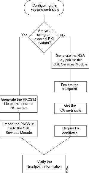
Configuring a Trustpoint
You can configure a trustpoint by either of the following methods:
•![]() Manually configure the trustpoint by generating a key pair, declaring the trustpoint, getting the CA certificate, and sending an enrollment request to a CA on behalf of the SSL server. See the "Manually Configuring the Trustpoint" section for details.
Manually configure the trustpoint by generating a key pair, declaring the trustpoint, getting the CA certificate, and sending an enrollment request to a CA on behalf of the SSL server. See the "Manually Configuring the Trustpoint" section for details.
Note ![]() Cisco IOS software supports the Simple Certificate Enrollment Protocol (SCEP).
Cisco IOS software supports the Simple Certificate Enrollment Protocol (SCEP).
•![]() Use an external PKI system to generate a PKCS12 file, and then import this file to the module. See the "Importing and Exporting Key Pairs and Certificates" section for details.
Use an external PKI system to generate a PKCS12 file, and then import this file to the module. See the "Importing and Exporting Key Pairs and Certificates" section for details.
An external PKI system is a server or a PKI administration system that generates key pairs and enrolls for certificates from a CA or a key and certificate archival system. The Public-Key Cryptography Standards (PKCS12) specifies the transfer syntax for personal identity information, including the private keys and certificates. This information is packaged into an encrypted file. To open the encrypted file, you must know a pass phrase. The encryption key is derived from the pass phrase.
Note ![]() You do not need to configure a trustpoint before importing the PKCS12 file. Importing keys and certificates from a PKCS12 file creates the trustpoint automatically, if it does not already exist.
You do not need to configure a trustpoint before importing the PKCS12 file. Importing keys and certificates from a PKCS12 file creates the trustpoint automatically, if it does not already exist.
See Figure 3-1 for an overview on configuring a trustpoint.
Figure 3-1 Trustpoint Configuration Overview
Manually Configuring the Trustpoint
To manually configure a trustpoint, complete the following tasks:
Generating RSA Key Pairs
Note ![]() The first key pair generated enables SSH on the module. If you are using SSH, configure a key pair for SSH. See the "Configuring SSH" section.
The first key pair generated enables SSH on the module. If you are using SSH, configure a key pair for SSH. See the "Configuring SSH" section.
RSA is the public key cryptographic system developed by Ron Rivest, Adi Shamir, and Leonard Aldeman. RSA algorithm is widely used by Certificate Authorities and SSL servers to generate key pairs. Each CA and each SSL server has its own RSA key pair. The SSL server sends its public key to the CA when enrolling for a certificate. The SSL server uses the certificate to prove its identity to clients when setting up the SSL session.
The SSL server keeps the private key in a secure storage, and sends only the public key to the CA which uses its private key to sign the certificate that contains the server's public key and other identifying information about the server.
Each CA keeps the private key secret and uses the private key to sign certificates for its Subordinate CAs and SSL servers. The CA has a certificate that contains its public key.
The CAs form a hierarchy of one or more levels. The top level CA is called the Root CA. The lower level CAs are called Intermediate or Subordinate CAs. The Root CA has a self-signed certificate, and it signs the certificate for the next level Subordinate CA, which in turn signs the certificate for the next lower level CA, and so on. The lowest level CA signs the certificate for the SSL server.
Note ![]() The SSL Services Module currently supports up to two levels of CA.
The SSL Services Module currently supports up to two levels of CA.
These certificates form a chain with the server certificate at the bottom and the Root CA's self-signed certificate at the top. Each signature is formed by using the private key of the issuing CA to encrypt a hash digest of the certificate body. The signature is attached to the end of the certificate body to form the complete certificate.
When setting up an SSL session, the SSL server sends its certificate chain to the client. The client verifies the signature of each certificate up the chain by retrieving the public key from the next higher-level certificate to decrypt the signature attached to the certificate body. The decryption result is compared with the hash digest of the certificate body. Verification terminates when one of the CA certificates in the chain matches one of the trusted CA certificates stored in the client's own database.
If the top-level CA certificate is reached in the chain, and there is no match of trusted self-signed certificates, the client may terminate the session, or prompt the user to view the certificates and determine if they can be trusted.
After the SSL client authenticates the server, it uses the public key from the server certificate to encrypt a secret and send it over to the server. The SSL server uses its private key to decrypt the secret. Both sides use the secret and two random numbers they exchanged to generate the key material required for the rest of the SSL session for data encryption, decryption and integrity checking.
Note ![]() The SSL Services Module supports only general-purpose keys.
The SSL Services Module supports only general-purpose keys.
When you generate general-purpose keys, only one pair of RSA keys is generated. Named key pairs allow you to have multiple RSA key pairs, enabling the Cisco IOS software to maintain a different key pair for each identity certificate. We recommend that you specify a name for the key pairs.
Note ![]() The generated key pair resides in system memory (RAM). They will be lost on power failure or module reset. You must enter the copy system:running-config nvram:startup-config command to save the running configuration, as well as save the key pairs to the private configuration file in the module NVRAM.
The generated key pair resides in system memory (RAM). They will be lost on power failure or module reset. You must enter the copy system:running-config nvram:startup-config command to save the running configuration, as well as save the key pairs to the private configuration file in the module NVRAM.
To generate RSA key pairs, perform this task:
|
|
|
|---|---|
ssl-proxy(config)# crypto key generate rsa general-keys key-label [exportable1 ] |
Generates RSA key pairs. |
1 The exportable keyword specifies that the key is allowed to be exported. You can specify that a key is exportable during key generation. Once the key is generated as either exportable or not exportable, it cannot be modified for the life of the key. |
Note ![]() When you generate RSA keys, you are prompted to enter a modulus length in bits. The SSL Services Module supports modulus lengths of 512, 768, 1024, 1536, and 2048 bits. Although you can specify 512 or 768, we recommend a minimum modulus length of 1024. A longer modulus takes longer to generate and takes longer to use, but offers stronger security.
When you generate RSA keys, you are prompted to enter a modulus length in bits. The SSL Services Module supports modulus lengths of 512, 768, 1024, 1536, and 2048 bits. Although you can specify 512 or 768, we recommend a minimum modulus length of 1024. A longer modulus takes longer to generate and takes longer to use, but offers stronger security.
This example shows how to generate general-purpose RSA keys:
ssl-proxy(config)# crypto key generate rsa general-keys kp1 exportable
The name for the keys will be: kp1
Choose the size of the key modulus in the range of 512 to 2048 for your General Purpose
Keys. Choosing a key modulus greater than 512 may take a few minutes.
How many bits in the modulus[512]? 1024
Generating RSA keys.... [OK].
Declaring the Trustpoint
You should declare one trustpoint to be used by the module for each certificate.
To declare the trustpoint that your module uses and specify characteristics for the trustpoint, perform this task beginning in global configuration mode:
|
|
|
|
|---|---|---|
Step 1 |
ssl-proxy(config)# crypto ca trustpoint trustpoint-label1 |
Declares the trustpoint that your module should use. Enabling this command puts you in ca-trustpoint configuration mode. |
Step 2 |
ssl-proxy(ca-trustpoint)# rsakeypair key-label |
Specifies which key pair to associate with the certificate. |
Step 3 |
ssl-proxy(ca-trustpoint)# enrollment [mode ra] [retry [period minutes] [count count]] url url |
Specifies the enrollment parameters for your CA. |
Step 4 |
ssl-proxy(ca-trustpoint)# ip-address server_ip_addr |
(Optional) Specifies the IP address of the proxy service which will use this certificate2 . |
Step 5 |
ssl-proxy(ca-trustpoint)# subject-name line3 , 4 |
(Optional) Configures the host name of the proxy service5 . |
Step 6 |
ssl-proxy(ca-trustpoint)# password password |
(Optional) Configures a challenge password. |
Step 7 |
ssl-proxy(ca-trustpoint)# exit |
Exits ca-trustpoint configuration mode. |
1 The trustpoint-label should match the key-label of the keys; however, this is not a requirement. 2 Some web browsers compare the IP address in the SSL server certificate with the IP address that might appear in the URL. If the IP addresses do not match, the browser may display a dialog box and ask the client to accept or reject this certificate. 3 For example, subject-name CN=server1.domain2.com, where server1 is the name of the SSL server that appears in the URL. The subject-name command uses the Lightweight Directory Access Protocol (LDAP) format. 4 Arguments specified in the subject name must be enclosed in quotation marks if they contain a comma. For example, O="Cisco, Inc." 5 Some browsers compare the CN field of the subject name in the SSL server certificate with the hostname that might appear in the URL. If the names do not match, the browser may display a dialog box and ask the client to accept or reject the certificate. Also, some browsers will reject the SSL session setup and silently close the session if the CN field is not defined in the certificate. |
This example shows how to declare the trustpoint PROXY1 and verify connectivity:
ssl-proxy(config)# crypto ca trustpoint PROXY1
ssl-proxy(ca-trustpoint)# rsakeypair PROXY1
ssl-proxy(ca-trustpoint)# enrollment url http://exampleCA.cisco.com
ssl-proxy(ca-trustpoint)# ip-address 10.0.0.1
ssl-proxy(ca-trustpoint)# password password
ssl-proxy(ca-trustpoint)# serial-number
ssl-proxy(ca-trustpoint)# subject-name C=US; ST=California; L=San Jose; O=Cisco; OU=Lab;
CN=host1.cisco.com
ssl-proxy(ca-trustpoint)# end
ssl-proxy#
ssl-proxy# ping example.cisco.com
Type escape sequence to abort.
Sending 5, 100-byte ICMP Echos to 20.0.0.1, timeout is 2 seconds:
!!!!!
Success rate is 100 percent (5/5), round-trip min/avg/max = 1/1/4 ms
ssl-proxy#
Getting the CA Certificate
For each trustpoint, you must get a certificate that contains the public key of the CA; multiple trustpoints can use the same CA.
Note ![]() Contact the CA to obtain the correct fingerprint of the certificate and verify the fingerprint displayed on the console.
Contact the CA to obtain the correct fingerprint of the certificate and verify the fingerprint displayed on the console.
To get the certificate that contains the public key of the CA, perform this task in global configuration mode:
This example shows how to get the certificate of the CA:
ssl-proxy(config)# crypto ca authenticate PROXY1
Certificate has the following attributes:
Fingerprint: A8D09689 74FB6587 02BFE0DC 2200B38A
% Do you accept this certificate? [yes/no]: y
Trustpoint CA certificate accepted.
ssl-proxy(config)# end
ssl-proxy#
Requesting a Certificate
You must obtain a signed certificate from the CA for each trustpoint.
To request signed certificates from the CA, perform this task in global configuration mode:
|
|
|
|---|---|
ssl-proxy(config)# crypto ca enroll trustpoint-label1 |
Requests a certificate for the trustpoint. |
1 You have the option to create a challenge password that is not saved with the configuration. This password is required in the event that your certificate needs to be revoked, so you must remember this password. |
Note ![]() If your module or switch reboots after you have entered the crypto ca enroll command but before you have received the certificates, you must reenter the command and notify the CA administrator.
If your module or switch reboots after you have entered the crypto ca enroll command but before you have received the certificates, you must reenter the command and notify the CA administrator.
This example shows how to request a certificate:
ssl-proxy(config)# crypto ca enroll PROXY1
%
% Start certificate enrollment ..
% The subject name in the certificate will be: C=US; ST=California; L=San Jose; O=Cisco;
OU=Lab; CN=host1.cisco.com
% The subject name in the certificate will be: host.cisco.com
% The serial number in the certificate will be: 00000000
% The IP address in the certificate is 10.0.0.1
% Certificate request sent to Certificate Authority
% The certificate request fingerprint will be displayed.
% The 'show crypto ca certificate' command will also show the fingerprint.
Fingerprint: 470DE382 65D8156B 0F84C2AF 4538B913
ssl-proxy(config)#end
After you configure the trustpoint, see the "Verifying Certificates and Trustpoints" section to verify the certificate and trustpoint information.
Importing and Exporting Key Pairs and Certificates
You can use an external PKI system to generate a PKCS12 file, and then import this file to the module. When creating a PKCS12 file, include the entire certificate chain, from server certificate to root certificate, and public and private keys.
You can also generate a PKCS12 file from the module and export it.
Note ![]() Imported key pairs cannot be exported.
Imported key pairs cannot be exported.
Note ![]() If you are using SSH, we recommend using SCP (secure file transfer) when importing or exporting a PKCS12 file. SCP authenticates the host and encrypts the transfer session.
If you are using SSH, we recommend using SCP (secure file transfer) when importing or exporting a PKCS12 file. SCP authenticates the host and encrypts the transfer session.
To import or export a PKCS12 file, perform this task:
|
|
|
|---|---|
ssl-proxy(config)# crypto ca {import |
export} trustpoint_label pkcs12 {scp:|
ftp:| nvram:| rcp:|
tftp:}[pkcs12_filename1 ] pass_phrase2
|
Imports or exports a PKCS12 file. Note |
1 If you do not specify pkcs12_filename, you will be prompted to accept the default filename (the default filename is the trustpoint_label) or enter the filename. For ftp: or tftp:, include the full path in the pkcs12_filename. 2 You will receive an error if you enter the pass phrase incorrectly. |
This example shows how to import a PKCS12 file using SCP:
ssl-proxy(config)# crypto ca import TP2 pkcs12 scp: sky is blue
Address or name of remote host []? 10.1.1.1
Source username [ssl-proxy]? admin-1
Source filename [TP2]? /users/admin-1/pkcs12/TP2.p12
Password:password
Sending file modes:C0644 4379 TP2.p12
!
ssl-proxy(config)#
*Aug 22 12:30:00.531:%CRYPTO-6-PKCS12IMPORT_SUCCESS:PKCS #12 Successfully Imported.
ssl-proxy(config)#
This example shows how to export a PKCS12 file using SCP:
ssl-proxy(config)#crypto ca export TP1 pkcs12 scp: sky is blue
Address or name of remote host []? 10.1.1.1
Destination username [ssl-proxy]? admin-1
Destination filename [TP1]? TP1.p12
Password:
Writing TP1.p12 Writing pkcs12 file to scp://admin-1@10.1.1.1/TP1.p12
Password:
!
CRYPTO_PKI:Exported PKCS12 file successfully.
ssl-proxy(config)#
This example shows how to import a PKCS12 file using FTP:
ssl-proxy(config)#crypto ca import TP2 pkcs12 ftp: sky is blue
Address or name of remote host []? 10.1.1.1
Source filename [TP2]? /admin-1/pkcs12/PK-1024
Loading /admin-1/pkcs12/PK-1024 !
[OK - 4339/4096 bytes]
ssl-proxy(config)#
This example shows how to export a PKCS12 file using FTP:
ssl-sanjose1(config)#crypto ca export TP1 pkcs12 ftp: sky is blue
Address or name of remote host []? 10.1.1.1
Destination filename [TP1]? /admin-1/pkcs12/PK-1024
Writing pkcs12 file to ftp://10.1.1.1//admin-1/pkcs12/PK-1024
Writing /admin-1/pkcs12/PK-1024 !!
CRYPTO_PKI:Exported PKCS12 file successfully.
ssl-proxy(config)#
After you import the PKCS12 file, see the "Verifying Certificates and Trustpoints" section to verify the certificate and trustpoint information.
Importing a Test Certificate
A test PKCS12 file (test/testssl.p12) is embedded in the SSL software on the module. You can install the file into NVRAM for testing purposes and for proof of concept. After the PKCS12 file is installed, you can import it to a trustpoint, and then assign it to a proxy service configured for testing.
To install and import the test file, perform this task:
This example shows how to import the test PKCS12 file:
ssl-proxy# test ssl-proxy
certificate install
% Opening file, please wait ...
% Writing, please wait ............
% Please use the following config command to import the file.
"crypto ca import <trustpoint-name> pkcs12 nvram:test/testssl.p12 sky is blue"
% Then you can assign the trustpoint to a proxy service for testing.
ssl-proxy# configure terminal
Enter configuration commands, one per line. End with CNTL/Z.
ssl-proxy(config)# crypto ca import test-tp pkcs12 nvram:test/testssl.p12 sky is blue
Source filename [test/testssl.p12]?
ssl-proxy(config)#
ssl-proxy(config)# ssl-proxy service test-service
ssl-proxy(config-ssl-proxy)# certificate rsa general-purpose trustpoint test-tp
ssl-proxy(config-ssl-proxy)# end
ssl-proxy#
Verifying Certificates and Trustpoints
To verify information about your certificates and trustpoints, perform this task in EXEC mode:
Sharing Keys and Certificates
The SSL Services Module supports the sharing of the same key pair by multiple certificates. However, this is not a good practice, because if one key pair is compromised, all the certificates must be revoked and replaced.
Because proxy services are added and removed at different times, the certificates also expire at different times. Some CAs require you to refresh the key pair at the time of renewal. If certificates share one key pair, you need to renew the certificates at the same time. In general, it is easier to manage certificates if each certificate has its own key pair.
The SSL Module does not impose any restrictions on sharing certificates among multiple proxy services and multiple SSL Services Modules. The same trustpoint can be assigned to multiple proxy services.
From a business point of view, the CA may impose restrictions (for example, on the number of servers in a server farm that can use the same certificate). There may be contractual or licensing agreements regarding certificate sharing. Consult with the CA or the legal staff regarding business contractual aspects.
In practice, some web browsers compare the subject name of the server certificate with the hostname or the IP address that appears on the URL. In case the subject name does not match the hostname or IP address, a dialog box appears, prompting the user to verify and accept the certificate. To avoid this step, limit the sharing of certificates based on the hostname or IP address.
Saving Your Configuration

Always remember to save your work when you make configuration changes.
To save your configuration to NVRAM, perform this task:
|
|
|
|---|---|
ssl-proxy# copy /erase1 system:running-config nvram:startup-config |
Saves the configuration, key pairs, and certificate to NVRAM. The key pairs are stored in the private configuration file, and each certificate is stored as a binary file in NVRAM. On bootup, the module will not need to query the CA to obtain the certificates or to auto-enroll. |
1 For security reasons, we recommend that you enter the /erase option to erase the public and the private configuration files before updating the NVRAM. If you do not enter this option, the key pairs from the old private configuration file may remain in the NVRAM. |
Note ![]() If you have a large number of files in NVRAM, this task may take up to 2 minutes to finish.
If you have a large number of files in NVRAM, this task may take up to 2 minutes to finish.
Oversized Configuration
If you save an oversized configuration with more than 256 proxy services and 356 certificates, you may encounter a situation where you could corrupt the contents in the NVRAM.
We recommend that you always copy to running-config before saving to NVRAM. When you save the running-config file to a remote server, each certificate is saved as a hex dump in the file. If you copy the running-config file back to running-config and then save it to NVRAM, the certificates are saved again, but as binary files. However, if you copy the running-config file directly from the remote server to startup-config, the certificates saved as hex dumps are also saved, resulting in two copies of the same certificate: one in hex dump and one as a binary file. This is unnecessary, and if the remote file is very large, it may overwrite part of the contents in the NVRAM, which could corrupt the contents.
Verifying the Saved Configuration
To verify the saved configuration, perform this task:
|
|
|
|
|---|---|---|
Step 1 |
ssl-proxy# show startup-config |
Displays the startup configuration. |
Step 2 |
ssl-proxy# directory nvram: |
Displays the names and sizes of the files in NVRAM. |
Note ![]() With the maximum number or proxy services (256) and certificates (356) configured, the output takes up to seven minutes to display.
With the maximum number or proxy services (256) and certificates (356) configured, the output takes up to seven minutes to display.
Erasing the Saved Configuration
To erase a saved configuration, perform this task:
Note ![]() If you have a large number of files in NVRAM, this task may take up to 2 minutes to finish.
If you have a large number of files in NVRAM, this task may take up to 2 minutes to finish.
Backing Up Keys and Certificates
If an event occurs that interrupts the process of saving the keys and certificates to NVRAM (for example, a power failure), you could lose the keys and certificates being saved. You can obtain public keys and certificates from the CA. However, you cannot recover private keys.
If a secure server is available, you can back up key pairs and the associated certificate chain by exporting each trustpoint to a PKCS12 file. You can then import the PKCS12 files to recover the keys and certificates.
Security Guidelines
When backing up keys and certificates, observe the following guidelines:
•![]() For each PKCS12, you must select a pass phrase that cannot be easily guessed, and keep the pass phrase well protected. Do not store the PKCS12 file in clear form.
For each PKCS12, you must select a pass phrase that cannot be easily guessed, and keep the pass phrase well protected. Do not store the PKCS12 file in clear form.
•![]() The backup server must be secure. Allow only authorized personnel to access the backup server.
The backup server must be secure. Allow only authorized personnel to access the backup server.
•![]() When importing or exporting the PKCS12 file (in which you are required to enter a pass phrase), connect directly to the module console or use an SSH session.
When importing or exporting the PKCS12 file (in which you are required to enter a pass phrase), connect directly to the module console or use an SSH session.
•![]() Use SCP for file transfer.
Use SCP for file transfer.
Monitoring and Maintaining Keys and Certificates
The following tasks in this section are optional:
•![]() Deleting RSA Keys from the Module
Deleting RSA Keys from the Module
•![]() Viewing Keys and Certificates
Viewing Keys and Certificates
•![]() Deleting Certificates from the Configuration
Deleting Certificates from the Configuration
Deleting RSA Keys from the Module
Under certain circumstances you may want to delete the module's RSA keys. For example, if you believe the RSA keys were compromised in some way and should no longer be used, you should delete the keys.
To delete all RSA keys from the module, perform this task in global configuration mode:
After you delete a module's RSA keys, complete these two additional tasks:
•![]() Ask the CA administrator to revoke your module's certificates at the CA; you must supply the challenge password that you created when you originally obtained the module's certificates with the crypto ca enroll command.
Ask the CA administrator to revoke your module's certificates at the CA; you must supply the challenge password that you created when you originally obtained the module's certificates with the crypto ca enroll command.
•![]() Manually remove the trustpoint from the configuration, as described in the "Deleting Certificates from the Configuration" section.
Manually remove the trustpoint from the configuration, as described in the "Deleting Certificates from the Configuration" section.
Viewing Keys and Certificates
To view keys and certificates, enter these commands in EXEC mode:
Deleting Certificates from the Configuration
The module saves its own certificates and the certificate of the CA. You can delete certificates that are saved on the module.
To delete the certificate from the module configuration, perform this task in global configuration mode:
|
|
|
|---|---|
ssl-proxy(config)# no crypto ca trustpoint trustpoint-label |
Deletes the certificate. |
Assigning a Certificate to a Proxy Service
When you enter the certificate rsa general-purpose trustpoint trustpoint_label subcommand (under the ssl-proxy service proxy_service command), a certificate to the specified proxy service is assigned. You can enter the certificate rsa general-purpose trustpoint subcommand multiple times for the proxy service.
If the trustpoint label is modified, the proxy service is momentarily taken out of service during the transition. Existing connections continue to use the old certificate until the connections are closed or cleared. New connections use the certificate from the new trustpoint, and the service is available again.
However, if the new trustpoint does not have a certificate yet, the operational status of the service remains down. New connections are not established until the new certificate is available. If the certificate is deleted by entering the no certificate rsa general-purpose trustpoint subcommand, the existing connections continue to use the certificate until the connections are closed or cleared. Although the certificate is obsolete, it is not removed from the proxy service until all the connections are closed or cleared.
The following example shows how to assign a trustpoint to a proxy service:
ssl-proxy# configure terminal
ssl-proxy(config)# ssl-proxy service s2
ssl-proxy(config-ssl-proxy)# virtual ip 10.1.1.2 p tcp p 443
ssl-proxy(config-ssl-proxy)# server ip 20.0.0.3 p tcp p 80
ssl-proxy(config-ssl-proxy)# inservice
ssl-proxy(config-ssl-proxy)# certficate rsa general trustpoint tp-1
ssl-proxy(config-ssl-proxy)# end
ssl-proxy#
ssl-proxy# show ssl-proxy service s2
Service id:6, bound_service_id:262
Virtual IP:10.1.1.2, port:443
Server IP:20.0.0.3, port:80
rsa-general-purpose certificate trustpoint:tp-1
Certificate chain in use for new connections:
Server Certificate:
Key Label:tp-1
Serial Number:3C2CD2330001000000DB
Root CA Certificate:
Serial Number:313AD6510D25ABAE4626E96305511AC4
Certificate chain complete
Admin Status:up
Operation Status:up
ssl-proxy#
The following example shows how to change a trustpoint for a proxy service:
Note ![]() The existing connections continue to use the old certificate until the connections are closed. The operational status of the service changes from up to down, and then up again. New connections use the new certificate.
The existing connections continue to use the old certificate until the connections are closed. The operational status of the service changes from up to down, and then up again. New connections use the new certificate.
ssl-proxy# configure terminal
ssl-proxy(config)# ssl-proxy service s2
ssl-proxy(config-ssl-proxy)# certificate rsa general trustpoint tp-2
ssl-proxy(config-ssl-proxy)# end
ssl-proxy#
ssl-proxy# show ssl-proxy service s2
Service id:6, bound_service_id:262
Virtual IP:10.1.1.2, port:443
Server IP:20.0.0.3, port:80
rsa-general-purpose certificate trustpoint:tp-2
Certificate chain in use for new connections:
Server Certificate:
Key Label:k2
Serial Number:70FCBFEC000100000D65
Root CA Certificate:
Serial Number:313AD6510D25ABAE4626E96305511AC4
Obsolete certificate chain in use for old connections:
Server Certificate:
Key Label:tp-1
Serial Number:3C2CD2330001000000DB
Root CA Certificate:
Serial Number:313AD6510D25ABAE4626E96305511AC4
Certificate chain complete
Admin Status:up
Operation Status:up
ssl-proxy#
Renewing a Certificate
Some CAs require you to generate a new key pair to renew a certificate, while other CAs allow you to use the key pair of the expiring certificate to renew a certificate. Both cases are supported on the SSL Services Module.
The SSL server certificates usually expire in one or two years. Graceful rollover of certificates avoids sudden cut-off of services.
In the following example, proxy service s2 is assigned trustpoint t2:
ssl-proxy# configure terminal
Enter configuration commands, one per line. End with CNTL/Z.
ssl-proxy(config)# ssl-proxy service s2
ssl-proxy(config-ssl-proxy)# certificate rsa general-purpose trustpoint t2
ssl-proxy(config-ssl-proxy)# end
ssl-proxy#
ssl-proxy# show ssl-proxy service s2
Service id:0, bound_service_id:256
Virtual IP:10.1.1.1, port:443
Server IP:10.1.1.10, port:80
Nat pool:pool2
rsa-general-purpose certificate trustpoint:t2
Certificate chain in use for new connections:
Server Certificate:
Key Label:k2
Serial Number:1DFBB1FD000100000D48
Root CA Certificate:
Serial Number:313AD6510D25ABAE4626E96305511AC4
Certificate chain complete
Admin Status:up
Operation Status:up
In the following example, the key pair for trustpoint t2 is refreshed, and the old certificate is deleted from the IOS database. Graceful rollover starts automatically for proxy service s2.
ssl-proxy# configure terminal
Enter configuration commands, one per line. End with CNTL/Z.
ssl-proxy(config)# crypto key generate rsa general-key k2 exportable
% You already have RSA keys defined named k2.
% Do you really want to replace them? [yes/no]:yes
Choose the size of the key modulus in the range of 360 to 2048 for your
General Purpose Keys. Choosing a key modulus greater than 512 may take
a few minutes.
How many bits in the modulus [512]:1024
% Generating 1024 bit RSA keys ...[OK]
ssl-proxy(config)#end
ssl-proxy# show ssl-proxy service s2
Service id:0, bound_service_id:256
Virtual IP:10.1.1.1, port:443
Server IP:10.1.1.10, port:80
Nat pool:pool2
rsa-general-purpose certificate trustpoint:t2
Certificate chain in graceful rollover, being renewed:
Server Certificate:
Key Label:k2
Serial Number:1DFBB1FD000100000D48
Root CA Certificate:
Serial Number:313AD6510D25ABAE4626E96305511AC4
Server certificate in graceful rollover
Admin Status:up
Operation Status:up
In the following example, existing and new connections use the old certificate until trustpoint t2 reenrolls. After trustpoint t2 reenrolls, new connections use the new certificate; existing connections continue to use the old certificate until the connctions are closed.
ssl-proxy# configure terminal
Enter configuration commands, one per line. End with CNTL/Z.
ssl-proxy(config)# crypto ca enroll t2
%
% Start certificate enrollment ..
% The subject name in the certificate will be:CN=host1.cisco.com
% The subject name in the certificate will be:ssl-proxy.cisco.com
% The serial number in the certificate will be:00000000
% The IP address in the certificate is 10.1.1.1
% Certificate request sent to Certificate Authority
% The certificate request fingerprint will be displayed.
% The 'show crypto ca certificate' command will also show the fingerprint.
Fingerprint: 6518C579 A0498063 C5795057 A6170 075
ssl-proxy(config)# end
*Sep 24 15:19:34.339:%CRYPTO-6-CERTRET:Certificate received from Certificate Authority
ssl-proxy# show ssl-proxy service s2
Service id:0, bound_service_id:256
Virtual IP:10.1.1.1, port:443
Server IP:10.1.1.10, port:80
Nat pool:pool2
rsa-general-purpose certificate trustpoint:t2
Certificate chain in use for new connections:
Server Certificate:
Key Label:k2
Serial Number:2475A2FC000100000D4D
Root CA Certificate:
Serial Number:313AD6510D25ABAE4626E96305511AC4
Obsolete certificate chain in use for old connections:
Server Certificate:
Key Label:k2
Serial Number:1DFBB1FD000100000D48
Root CA Certificate:
Serial Number:313AD6510D25ABAE4626E96305511AC4
Certificate chain complete
Admin Status:up
Operation Status:up
In the following example, the obsolete certificate is removed after all of the existing connections are closed.
ssl-proxy# show ssl-proxy service s2
Service id:0, bound_service_id:256
Virtual IP:10.1.1.1, port:443
Server IP:10.1.1.10, port:80
Nat pool:pool2
rsa-general-purpose certificate trustpoint:t2
Certificate chain in use for new connections:
Server Certificate:
Key Label:k2
Serial Number:2475A2FC000100000D4D
Root CA Certificate:
Serial Number:313AD6510D25ABAE4626E96305511AC4
Certificate chain complete
Admin Status:up
Operation Status:up
Enabling Key and Certificate History
When you enter the ssl-proxy pki history command, the SSL proxy services key and certificate history are enabled. This history creates a record for each addition or deletion of the key pair and certificate chain for a proxy service.
When you enter the show ssl-proxy certificate-history command, the records are displayed. Each record logs the service name, key pair name, time of generation or import, trustpoint name, certificate subject name and issuer name, serial number, and date.
You can store up to 512 records in memory. For each record, a syslog message is generated. The oldest records are deleted after the limit of 512 records is reached.
To enable key and certificate history and display the records, perform this task:
This example shows how to enable key and certificate history and display the records for a specified proxy service:
ssl-proxy# configure terminal
Enter configuration commands, one per line. End with CNTL/Z.
ssl-proxy(config)#ssl-proxy pki history
ssl-proxy(config)#end
ssl-proxy# show ssl-proxy certificate-history service s2
Record 1, Timestamp:00:00:22, 17:44:18 UTC Sep 29 2002
Installed Server Certificate, Index 0
Proxy Service:s2, Trust Point:t2
Key Pair Name:k2, Key Usage:RSA General Purpose, Not Exportable
Time of Key Generation:06:29:08 UTC Sep 28 2002
Subject Name:CN = host1.cisco.com, OID.1.2.840.113549.1.9.2 = ssl-proxy.cisco.com, OID.1.2.840.113549.1.9.8 = 10.1.1.1
Issuer Name:CN = TestCA, OU = Lab, O = Cisco Systems, L = San Jose, ST = CA, C = US, EA =<16> simpson-pki@cisco.com
Serial Number:3728ADCD000100000D4F
Validity Start Time:15:56:55 UTC Sep 28 2002
End Time:16:06:55 UTC Sep 28 2003
Renew Time:00:00:00 UTC Jan 1 1970
End of Certificate Record
Total number of certificate history records displayed = 1
Configuring SSL Proxy Services
You define SSL proxy services using the ssl-proxy service ssl_proxy_name command. You can configure the virtual IP address and port associated with the proxy service and the associated target IP address and port. You also can define TCP and SSL policies for both client (virtual) and server (server) sides of the proxy.
To configure SSL proxy services, perform this task:
|
|
|
|
|---|---|---|
Step 1 |
ssl-proxy(config)# ssl-proxy service proxy_name |
Defines the name of the SSL proxy service. Note |
Step 2 |
ssl-proxy(config-ssl-proxy)# virtual ipaddr ip_addr protocol tcp port port [secondary1 ,2 ] |
Defines the virtual server IP address, transport protocol (TCP), and port number for which the SSL Services Module is the proxy. |
Step 3 |
ssl-proxy(config-ssl-proxy)# virtual policy tcp tcp_policy_name3 |
Applies a TCP policy to the client side of the proxy server. See the "Configuring TCP Policy" section for TCP policy parameters. |
Step 4 |
ssl-proxy(config-ssl-proxy)# virtual policy ssl ssl_policy_name3 |
Applies an SSL policy to the client side of the proxy server. See the "Configuring SSL Policy" section for SSL policy parameters. |
Step 5 |
ssl-proxy(config-ssl-proxy)# server ipaddr ip_addr protocol tcp port port |
Defines the IP address, port number, and the transport protocol of the target server for the proxy. Note |
Step 6 |
ssl-proxy(config-ssl-proxy)# server policy tcp tcp_policy_name |
Applies a TCP policy to the server side of the proxy server. See the "Configuring TCP Policy" section |
Step 7 |
ssl-proxy(config-ssl-proxy)# nat
{server | client natpool_name}
|
Specifies the usage of either server NAT4 or client NAT for the server-side connection opened by the SSL Services Module. See the "Configuring NAT" section. |
Step 8 |
ssl-proxy(config-ssl-proxy)# certificate rsa general-purpose trustpoint trustpoint_label |
Applies a trustpoint configuration to the proxy server5 . Note |
Step 9 |
ssl-proxy(config-ssl-proxy)# inservice |
Sets the proxy server as administratively Up. |
1 Enter the secondary keyword when the SSL Services Module is used in a standalone configuration or when the SSL Services Module is configured as a real server in unsecured mode on the CSM (see the "Configuring Different Modes of Operation" section). When you enter the secondary keyword, the SSL Services Module does not respond to ARP requests of the virtual IP address. 2 If you configure multiple proxy services using the same virtual IP address with different port numbers, all the proxy services must have the secondary keyword applied the same way: either specified for all proxy services, or not specified for any proxy service. 3 If you create a policy without specifying any parameters, the policy is created using the default values. 4 NAT = network address translation 5 If the key (modulus) size is other than 512, 768, 1024, 1536, or 2048, you will receive an error and the trustpoint configuration is not applied. Replace the key by generating a key (using the same key_label) and specifying a supported modulus size, then repeat Step 8. |
This example shows how to configure SSL proxy services:
ssl-proxy(config)# ssl-proxy service proxy1
ssl-proxy(config-ssl-proxy)# virtual ipaddr 10.1.1.100 protocol tcp port 443
ssl-proxy(config-ssl-proxy)# server ipaddr 10.1.1.1 protocol tcp port 80
ssl-proxy(config-ssl-proxy)# virtual policy tcp tcp2
ssl-proxy(config-ssl-proxy)# server policy tcp tcp2
ssl-proxy(config-ssl-proxy)# virtual policy ssl ssl1
ssl-proxy(config-ssl-proxy)# nat client t2
ssl-proxy(config-ssl-proxy)# certificate rsa general-purpose trustpoint tp1
ssl-proxy(config-ssl-proxy)# inservice
ssl-proxy(config-ssl-proxy)# end
ssl-proxy#
Configuring Different Modes of Operation
The SSL Services Module operates either in a standalone configuration or with a Content Switching Module (CSM). In a standalone configuration, secure traffic is directed to the SSL Services Module using policy-based routing. When used with a CSM, only encrypted client traffic is forwarded to the SSL Services Module, while clear text traffic is forwarded to real servers.
The following sections describes how to configure the SSL Services Module in a standalone configuration or with a CSM:
•![]() Configuring Policy-Based Routing
Configuring Policy-Based Routing
•![]() Configuring the Content Switching Module
Configuring the Content Switching Module
Figure 3-2 shows a sample network topology with an SSL Services Module and a CSM in a single Catalyst 6500 series switch.
Figure 3-2 Sample Network Layout—SSL Services Module with CSM
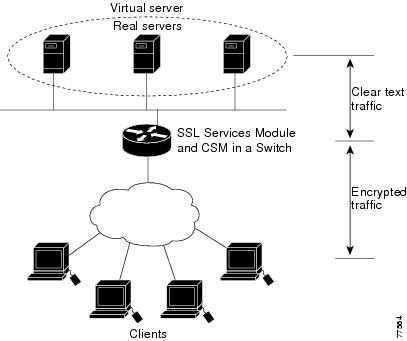
Configuring Policy-Based Routing
In a standalone configuration, encrypted SSL traffic is directed to the SSL Services Module using policy-based routing.
When you configure policy-based routing on the SSL Services Module, use the following guidelines:
•![]() Configure clients and servers on separate subnets.
Configure clients and servers on separate subnets.
•![]() Configure two VLANs (one for each subnet) on the switch.
Configure two VLANs (one for each subnet) on the switch.
•![]() Configure IP interfaces on each VLAN.
Configure IP interfaces on each VLAN.
•![]() Configure an IP interface on the server-side VLAN of the SSL Services Module.
Configure an IP interface on the server-side VLAN of the SSL Services Module.
Two flows exist for each direction of traffic. In the client-to-server direction, traffic flow originates from the client as either clear text or as encrypted data. (See Figure 3-3.) In the server-to-client direction, all traffic originates from the server as clear text. However, depending on the source port, the traffic in the server-to-client direction may or may not be encrypted by the SSL Services Module before being forwarded to the client.
Figure 3-3 Client-to-Server Traffic Flow—Standalone Configuration
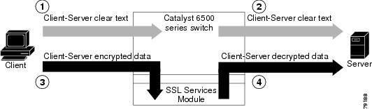
In Figure 3-3, the client sends clear text traffic to the server (as shown in flow 1). The switch then forwards clear text traffic to the server (flow 2).
The client sends encrypted traffic to the server (port 443); policy-based routing intercepts the traffic and forwards it to the SSL Services Module (flow 3). The SSL Services Module decrypts the traffic and forwards the stream to a well-known port (a port that has been configured on the server to expect decrypted traffic) (flow 4).
To enable policy-based routing, perform this task beginning in global configuration mode:
Policy-Based Routing Configuration Example
This section shows a policy-based routing configuration example using a real client and a real server.
Figure 3-4 Client-to-Server Traffic Flow Example
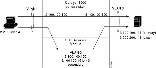
In Figure 3-4, the SSL Services Module and the real server both have the IP address 3.100.100.151. The IP address on the SSL Services Module is configured as secondary and will not reply to ARP requests for this address, which avoids the duplicate IP address issue.
The client (2.200.200.14) is attached to a VLAN 2 switchport (access mode). The client's default gateway is 2.100.100.100 (VLAN 2 IP address on the supervisor engine).
The real server is attached to a VLAN 3 switchport (access mode). The real server's default gateway is 3.100.100.100 (VLAN 3 IP address on the supervisor engine). The real server has two addresses: 3.100.100.151 (primary) and 3.200.200.146 (alias).
Clear-text (HTTP) traffic destined for 3.100.100.151 port 80 is sent directly to the real server, which bypasses the SSL Services Module.
With policy-based routing, SSL traffic destined for 3.100.100.151 port 443 is redirected to the SSL Services Module for decryption. The decrypted traffic is sent to 3.200.200.146 port 81 (the alias IP address for the real server). The return traffic from the real server is forwarded to the SSL Services Module. The module encrypts the traffic and sends it to client.
Configuring the Allowed VLANs
These examples show how to allow VLAN 3 between the SSL Services Module and the supervisor engine:
Cisco IOS:
Router# configure terminal
Enter configuration commands, one per line. End with CNTL/Z.
Router(config)# ssl-proxy module 8 allowed-vlan 3
Router(config)# ^Z
Router#
Router# show ssl-proxy module 8 state
SSL-proxy module 8 data-port:
Switchport:Enabled
Administrative Mode:trunk
Operational Mode:trunk
Administrative Trunking Encapsulation:dot1q
Operational Trunking Encapsulation:dot1q
Negotiation of Trunking:Off
Access Mode VLAN:1 (default)
Trunking Native Mode VLAN:1 (default)
Trunking VLANs Enabled:3
Pruning VLANs Enabled:2-1001
Vlans allowed on trunk:3
Vlans allowed and active in management domain:3
Vlans in spanning tree forwarding state and not pruned:
3
Allowed-vlan :3
Router#
Catalyst Operating System Software:
Console> (enable) set trunk 8/1
Adding vlans 3 to allowed list.
Console> (enable) show trunk 8/1
* - indicates vtp domain mismatch
# - indicates dot1q-all-tagged enabled on the port
Port Mode Encapsulation Status Native vlan
-------- ----------- ------------- ------------ -----------
8/1 nonegotiate dot1q not-trunking 1
Port Vlans allowed on trunk
-------- ---------------------------------------------------------------------
8/1 3
Port Vlans allowed and active in management domain
-------- ---------------------------------------------------------------------
8/1 3
Port Vlans in spanning tree forwarding state and not pruned
-------- ---------------------------------------------------------------------
8/1 3
Configuring the Access List and Route Map
This example shows how to configure the access list and route map for redirecting SSL traffic from the client to the SSL Services Module, and for redirecting clear text traffic from the real server to the SSL Services Module:
Router# configure terminal
Enter configuration commands, one per line. End with CNTL/Z.
Router(config)#
Router(config)# ip access-list extended redirect_ssl
Router(config-ext-nacl)# permit tcp any 3.0.0.0 0.255.255.255 eq 443
Router(config-ext-nacl)# !
Router(config-ext-nacl)# ip access-list extended reverse_traffic
Router(config-ext-nacl)# permit tcp 3.0.0.0 0.255.255.255 eq 81 any
Router(config-ext-nacl)# !
Router(config-ext-nacl)# route-map redirect_ssl permit
Router(config-route-map)# match ip address redirect_ssl
Router(config-route-map)# set ip next-hop 3.100.100.150
Router(config-route-map)# !
Router(config-route-map)# route-map reverse_traffic permit
Router(config-route-map)# match ip address reverse_traffic
Router(config-route-map)# set ip next-hop 3.100.100.150
Router(config-route-map)# !
Router(config-route-map)# interface Vlan2
Router(config-if)# ip address 2.100.100.100 255.0.0.0
Router(config-if)# ip policy route-map redirect_ssl
Router(config-if)# !
Router(config-if)# interface Vlan3
Router(config-if)# ip address 3.100.100.100 255.0.0.0
Router(config-if)# ip policy route-map reverse_traffic
Router(config-if)# !
Router(config-if)#^Z
Router#
Importing a Test Certificate
This example shows how to import the test certificate. For information on configuring a trustpoint and obtaining a certificate, see the "Configuring a Trustpoint" section
ssl-proxy# test ssl-proxy certificate install
% Opening file, please wait ...
% Writing, please wait ............
% Please use the following config command to import the file.
"crypto ca import <trustpoint-name> pkcs12 nvram:test/testssl.p12 sky is blue"
% Then you can assign the trustpoint to a proxy service for testing.
*Oct  9 19:49:17.570:%STE-6-PKI_TEST_CERT_INSTALL:Test key and certificate was installed
into NVRAM in a PKCS#12 file.
ssl-proxy# configure terminal
ssl-proxy(config)# crypto ca import sample pkcs12 nvram:sky is blue
Source filename [sample]? test/testssl.p12
ssl-proxy(config)#
*Oct 9 19:51:04.674:%SSH-5-ENABLED:SSH 1.5 has been enabled
*Oct 9 19:51:04.678:%CRYPTO-6-PKCS12IMPORT_SUCCESS:PKCS #12 Successfully Imported.
ssl-proxy(config)# ^Z
ssl-proxy#
Configuring the SSL Proxy VLAN
This example shows how to add an interface to VLAN 3 on the SSL Services Module:
ssl-proxy# configure terminal
Enter configuration commands, one per line. End with CNTL/Z.
ssl-proxy(config)# ssl-proxy vlan 3
ssl-proxy(config-vlan)# ipaddr 3.100.100.150 255.0.0.0
ssl-proxy(config-vlan)# gateway 3.100.100.100
ssl-proxy(config-vlan)# admin
ssl-proxy(config-vlan)# ^Z
ssl-proxy#
Configuring the SSL Proxy Service
This example shows how to add a specific proxy service that identifies a virtual IP address and a server IP address for each proxy:
ssl-proxy# configure terminal
Enter configuration commands, one per line. End with CNTL/Z.
ssl-proxy(config)# ssl-proxy service sample
ssl-proxy(config-ssl-proxy)# virtual ipaddr 3.100.100.151 protocol tcp port 443 secondary
ssl-proxy(config-ssl-proxy)# server ipaddr 3.200.200.146 protocol tcp port 81
ssl-proxy(config-ssl-proxy)# cert rsa general-purpose trustpoint sample
ssl-proxy(config-ssl-proxy)# inservice
ssl-proxy(config-ssl-proxy)# ^Z
ssl-proxy#
Verifying Service and Connections
This example shows how to verify the SSL proxy service and connections:
ssl-proxy# show ssl-proxy service sample
Service id:3, bound_service_id:259
Virtual IP:3.100.100.151, port:443
Server IP:3.200.200.146, port:81
rsa-general-purpose certificate trustpoint:sample
Certificate chain in use for new connections:
Server Certificate:
Key Label:sample
Serial Number:01
Root CA Certificate:
Serial Number:00
Certificate chain complete
Admin Status:up
Operation Status:up
ssl-proxy#
ssl-proxy# show ssl-proxy conn
Connections for TCP module 1
Local Address Remote Address VLAN Conid Send-Q Rwind Recv-Q State
------------------- ------------------- ----- ------ ------ ------ ------ ------
3.100.100.151.443 2.200.200.14.37820 3 470 0 32768 0 ESTABLISHED
2.200.200.14.37820 3.200.200.146.81 3 471 0 32768 0 ESTABLISHED
ssl-proxy#
Configuring the Content Switching Module
Note ![]() For detailed information on configuring the CSM, refer to the Catalyst 6500 Series Content Switching Module Installation and Configuration Note, Release 3.1, at this URL:
For detailed information on configuring the CSM, refer to the Catalyst 6500 Series Content Switching Module Installation and Configuration Note, Release 3.1, at this URL:
http://www.cisco.com/univercd/cc/td/doc/product/lan/cat6000/cfgnotes/csm_3_1/index.htm
The Content Switching Module (CSM) provides high-performance server load balancing (SLB) between network devices and server farms based on Layer 4 through Layer 7 packet information.
When you use the SSL Services Module with the CSM, only encrypted client traffic is forwarded to the SSL Services Module, while clear text traffic is forwarded to real servers.
The CSM parses for traffic destined to the server farm virtual IP address, port 443. The CSM forwards this traffic to the SSL Services Module without modifying the destination IP address. If there are multiple SSL Services Modules in the configuration, the CSM load balances the traffic across the SSL Services Modules. The SSL Services Module decrypts the traffic and forwards the new stream back to the CSM. The SSL Services Module does not change the destination IP address (the original server farm virtual IP address), but it does perform a port translation. With this new virtual IP address and port combination, the CSM balances the data across the servers in the server farm. (See Figure 3-5.)
Figure 3-5 Client-to-Server Traffic Flow—SSL Services Module and CSM
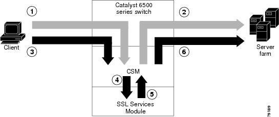
In Figure 3-5, clear text traffic is sent from the client to a virtual IP address, non-SSL port (for example, 80) (shown in flow 1). The CSM balances the clear text traffic across the servers in the server farm (flow 2).
Encrypted traffic is sent from the client to a virtual IP address, SSL port (443) (flow 3). The CSM forwards the encrypted traffic to the SSL Services Module (flow 4); if there is more than one SSL Services Module, the CSM balances the encrypted traffic across SSL Services Modules.
The SSL Services Module decrypts the traffic and forwards it to a virtual IP address and port on the CSM (flow 5).
The CSM balances the decrypted traffic across the servers in the server farm (flow 6).
On the return path, the CSM must monitor the port from which the server transmits data. If it is the standard clear text port (for example, 80), the data is forwarded back to the client unaltered, with the exception of the source address. If server NAT is configured on the clear text flow, the virtual IP address replaces the source IP address.
If traffic is destined to the virtual IP address and port 443, the CSM forwards this flow to the SSL Services Module. The SSL Services Module encrypts the traffic and performs port translation on the packet header. The SSL Services Module directs the traffic to the CSM with source port 443 (the SSL port to which the client originally directed encrypted traffic) so that the CSM can handle the reverse path traffic.
VLANs
As with normal CSM operation, you are required to configure separate client and server VLANs. If the CSM client and server VLANs are not on the same subnet, the CSM acts as a switch between the client and server VLANs.
To allow traffic to pass between the CSM and the SSL Services Module, you need to configure a single VLAN between them (see Figure 3-6); all flows between the CSM and the SSL Services Module are on that VLAN.
Figure 3-6 SSL Services Module with CSM—3-VLAN Configuration
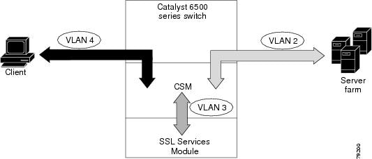
In Figure 3-6, VLAN 4 involves clear text and encrypted traffic between the client and the CSM virtual IP address.
VLAN 2 involves the following types of traffic between the server and the client:
•![]() Clear text traffic between the client and the server
Clear text traffic between the client and the server
•![]() Traffic sent by the client that was decrypted by the SSL Services Module
Traffic sent by the client that was decrypted by the SSL Services Module
•![]() Traffic sent by the server that needs to be encrypted by the SSL Services Module
Traffic sent by the server that needs to be encrypted by the SSL Services Module
VLAN 3 involves the following types of traffic between the CSM and the SSL Services Module:
•![]() Encrypted client traffic that needs to be decrypted
Encrypted client traffic that needs to be decrypted
•![]() Decrypted client traffic that needs to be forwarded to the server farm
Decrypted client traffic that needs to be forwarded to the server farm
•![]() Unencrypted server traffic that needs to be encrypted
Unencrypted server traffic that needs to be encrypted
•![]() Encrypted server traffic that needs to be forwarded back to the client
Encrypted server traffic that needs to be forwarded back to the client
To configure VLANs on the CSM, perform this task:
Server Farms
When you use the SSL Services Module with a CSM, the CSM sees two types of server farms. The first server farm is the traditional farm consisting of a group of real servers and is mapped to one or more virtual server IP addresses. You may or may not choose to allow server or client NAT to act on traffic going to these servers.
The second type of server farm consists of the SSL Services Modules that are present in the chassis. The CSM views these SSL Services Modules as real servers and balances SSL traffic across the modules.
To configure a server farm on the CSM, perform this task:
Virtual Servers
Three types of virtual servers are required for every real server farm supported in a CSM and SSL Services Module configuration. The main distinction between the three types of virtual servers is the port number. The clear text virtual server and the SSL virtual server have the same virtual IP address. The decryption virtual server may or may not have the same virtual IP address. The three types of virtual servers are as follows:
•![]() Clear text virtual server—The clear text virtual server is the destination for any clear text traffic sent by the client. Typically, this traffic is destined to port 80. The CSM balances traffic sent to this virtual server directly to a real server in the server farm. The SSL Services Module is uninvolved.
Clear text virtual server—The clear text virtual server is the destination for any clear text traffic sent by the client. Typically, this traffic is destined to port 80. The CSM balances traffic sent to this virtual server directly to a real server in the server farm. The SSL Services Module is uninvolved.
•![]() SSL virtual server—The SSL virtual server should be the destination for any SSL-encrypted traffic from the client to the server. This traffic is destined to port 443. The CSM forwards this type of traffic to the SSL Services Module for decryption.
SSL virtual server—The SSL virtual server should be the destination for any SSL-encrypted traffic from the client to the server. This traffic is destined to port 443. The CSM forwards this type of traffic to the SSL Services Module for decryption.
•![]() Decryption virtual server—After the SSL Services Module decrypts SSL traffic from the client, it forwards it back to the CSM, destined for the decryption virtual server. The CSM balances the traffic to a real server in the server farm, similar to the action it took for traffic destined to the clear text virtual server. The port associated with this decryption virtual server should match the port from which the real server has been configured to expect SSL Services Module-decrypted traffic.
Decryption virtual server—After the SSL Services Module decrypts SSL traffic from the client, it forwards it back to the CSM, destined for the decryption virtual server. The CSM balances the traffic to a real server in the server farm, similar to the action it took for traffic destined to the clear text virtual server. The port associated with this decryption virtual server should match the port from which the real server has been configured to expect SSL Services Module-decrypted traffic.
To configure a virtual server on the CSM, perform this task:
Sticky Connections
Note ![]() Configuring the SSL sticky feature requires CSM software release 3.1(1a) or later releases on the CSM.
Configuring the SSL sticky feature requires CSM software release 3.1(1a) or later releases on the CSM.
If a CSM and SSL Services Module configuration consists of multiple SSL Services Modules connected to a single CSM, configure the SSL sticky feature on the CSM to ensure that the CSM always forwards traffic from a particular client to the same SSL Services Module.
A 32-byte SSL session ID is created for each connection between a client and an SSL Services Module. With the SSL sticky feature configured, the CSM looks at a specific portion of the SSL session ID (the MAC address of the SSL Services Module) and load balances SSL traffic among the SSL Services Modules.
Note ![]() The MAC address of the SSL Services Module is always located at bytes 21 though 26 of the SSL session ID, even when the session ID is renegotiated.
The MAC address of the SSL Services Module is always located at bytes 21 though 26 of the SSL session ID, even when the session ID is renegotiated.
To configure a sticky connection on the CSM, perform this task:
CSM and SSL Services Module Configuration Example (Bridge Mode, No NAT)
This section describes a CSM and SSL Services Module configuration that contains two SSL Services Modules, a CSM, a client network, and a server farm that has three web servers (IP addresses 10.20.105.10, 10.20.105.20, 10.20.105.30).
In this example, the CSM client VLAN and CSM server VLAN for the SSL Services Modules are configured in the same IP subnet (bridge mode), while the CSM server VLAN for the web servers is in a separate IP subnet. (See Figure 3-7.)
The CSM is configured to perform no NAT when load balancing encrypted traffic to the SSL Services Modules. The SSL Services Modules are also configured to perform no NAT when sending decrypted traffic back to the CSM. The CSM is then configured to perform NAT for the decrypted traffic to the selected destination server.
Figure 3-7 Bridge Mode, No NAT Configuration Example
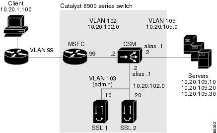
CSM Virtual Servers:
•![]() Client clear text traffic—10.20.102.100:80
Client clear text traffic—10.20.102.100:80
•![]() Client SSL traffic—10.20.102.100:443
Client SSL traffic—10.20.102.100:443
•![]() Decrypted traffic from SSL Services Modules—10.20.102.100:80
Decrypted traffic from SSL Services Modules—10.20.102.100:80
SSL Virtual Server:
•![]() 10.20.103.100:443 secondary
10.20.103.100:443 secondary
Figure 3-7 shows VLAN 102 and VLAN 103 in the same subnet, and VLAN 105 in a separate subnet.
Add all the required VLANs to the VLAN database, and configure the IP interface for VLAN 102 on the MSFC. Configure VLANs 102, 103 and 105 on the CSM. See the "Preparing to Configure the SSL Services Module" section for information on how to configure VLANs and IP interfaces.
Note ![]() While VLAN 102 exists as Layer 3 interface on the MSFC, both VLAN 103 and VLAN 105 exist only as VLANs in the VLAN database and as CSM VLANs, but do not have a corresponding Layer 3 interface on the MSFC.
While VLAN 102 exists as Layer 3 interface on the MSFC, both VLAN 103 and VLAN 105 exist only as VLANs in the VLAN database and as CSM VLANs, but do not have a corresponding Layer 3 interface on the MSFC.
This example shows how to create the client and server VLANs on the CSM installed in slot number 5:
Router# configure terminal
Enter configuration commands, one per line. End with CNTL/Z.
Router(config)# module csm 5
Router(config-module-csm)# vlan 102 client
Router(config-slb-vlan-client)# ip address 10.20.102.2 255.255.255.0
Router(config-slb-vlan-client)# gateway 10.20.102.99
Router(config-slb-vlan-client)# exit
Router(config-module-csm)# vlan 103 server
Router(config-slb-vlan-server)# ip address 10.20.102.2 255.255.255.0
Router(config-slb-vlan-server)# alias 10.20.102.1 255.255.255.0
Router(config-slb-vlan-server)# exit
Router(config-module-csm)# vlan 105 server
Router(config-slb-vlan-server)# ip address 10.20.105.2 255.255.255.0
Router(config-slb-vlan-server)# alias 10.20.105.1 255.255.255.0
Router(config-slb-vlan-server)# end
This example shows how to allow VLAN 103 between the SSL Services Module and the CSM:
Cisco IOS:
Router(config)# ssl-proxy module 4 allowed-vlan 103
Catalyst Operating System Software:
Console> (enable) set trunk 4/1 103
This example shows how to create the server farm of web servers (configured with server NAT) and the server farm of SSL Services Modules (configured with no server NAT):
Router# configure terminal
Enter configuration commands, one per line. End with CNTL/Z.
Router(config)# module csm 5
Router(config-module-csm)# serverfarm SSLFARM
Router(config-slb-sfarm)# no
nat server
Router(config-slb-sfarm)# real 10.20.102.10
Router(config-slb-real)#
inservice
Router(config-slb-real)# real 10.20.102.20
Router(config-slb-real)# inservice
Router(config-slb-real)# exit
Router(config-slb-sfarm)# exit
Router(config-module-csm)# serverfarm WEBSERVERS
Router(config-slb-sfarm)# nat server
Router(config-slb-sfarm)# real 10.20.105.10
Router(config-slb-real)# inservice
Router(config-slb-real)# real 10.20.105.20
Router(config-slb-real)# inservice
Router(config-slb-real)# real 10.20.105.30
Router(config-slb-real)# inservice
Router(config-slb-real)# end
This example shows how to configure the three virtual servers. In this example, the web servers are only receiving traffic to port 80, either directly from the clients or as decrypted traffic from the SSL Services Modules (since no port translation is configured).
The CSM distinguishes between requests received directly from the clients and requests received from the SSL Services Modules based on the VLAN from where the connections are received.
A sticky group is also configured to maintain stickiness based on the SSL ID.
Router# configure terminal
Enter configuration commands, one per line. End with CNTL/Z.
Router(config)# module csm 5
Router(config-module-csm)# sticky 100 ssl timeout 30
Router(config-module-csm)# vserver CLEAR_VIP
Router(config-slb-vserver)# virtual 10.20.102.100 tcp www
Router(config-slb-vserver)# vlan 102
Router(config-slb-vserver)# serverfarm WEBSERVERS
Router(config-slb-vserver)#
inservice
Router(config-slb-vserver)# exit
Router(config-module-csm)# vserver DECRYPT_VIP
Router(config-slb-vserver)# virtual 10.20.102.100 tcp www
Router(config-slb-vserver)# vlan 103
Router(config-slb-vserver)# serverfarm WEBSERVERS
Router(config-slb-vserver)# inservice
Router(config-slb-vserver)# exit
Router(config-module-csm)# vserver SSL_VIP
Router(config-slb-vserver)# virtual 10.20.102.100 tcp https
Router(config-slb-vserver)# vlan 102
Router(config-slb-vserver)# serverfarm SSLFARM
Router(config-slb-vserver)# sticky 30 group 100
Router(config-slb-vserver)# inservice
Router(config-slb-vserver)# end
This example shows how to configure the SSL Services Module to communicate with the CSM over VLAN 103, the admin VLAN:
ssl-proxy# configure terminal
Enter configuration commands, one per line. End with CNTL/Z.
ssl-proxy(config)# ssl-proxy vlan 103
ssl-proxy(config-vlan)# ipaddr 10.20.102.10 255.255.255.0
ssl-proxy(config-vlan)# gateway 10.20.102.99
ssl-proxy(config-vlan)# admin
ssl-proxy(config-vlan)# end
To complete the configuration, enter the ssl-proxy service command to create a new service on the SSL Services Module (test1). This example shows how to configure a virtual IP address that matches the virtual server created on the CSM (this virtual IP address is configured as secondary so that the SSL Services Module does not reply to ARP requests for this IP address). The service is configured to send decrypted traffic back to the CSM without performing NAT.
ssl-proxy# configure terminal
Enter configuration commands, one per line. End with CNTL/Z.
ssl-proxy(config)# ssl-proxy service test1
ssl-proxy(config-ssl-proxy)# virtual ipaddr 10.20.102.100 protocol tcp port 443 secondary
ssl-proxy(config-ssl-proxy)# server ipaddr 10.20.102.1 protocol tcp port 80
ssl-proxy(config-ssl-proxy)# certificate rsa general-purpose trustpoint testtp
ssl-proxy(config-ssl-proxy)# no nat server
ssl-proxy(config-ssl-proxy)# inservice
ssl-proxy(config-ssl-proxy)# end
The following examples show the output of the various show commands on the MSFC and CSM:
Router# show module csm 5 vlan detail
vlan IP address IP mask type
---------------------------------------------------
102 10.20.102.2 255.255.255.0 CLIENT
GATEWAYS
10.20.102.99
103 10.20.102.2 255.255.255.0 SERVER
ALIASES
IP address IP mask
--------------------------------
10.20.102.1 255.255.255.0
105 10.20.105.2 255.255.255.0 SERVER
ALIASES
IP address IP mask
--------------------------------
10.20.105.1 255.255.255.0
Router# show module csm 5 vserver detail
SSL_VIP, type = SLB, state = OPERATIONAL, v_index = 13
virtual = 10.20.102.100/32:443, TCP, service = NONE, advertise = FALSE
idle = 3600, replicate csrp = none, vlan = 102, pending = 30
max parse len = 600, persist rebalance = TRUE
conns = 0, total conns = 2
Default policy:
server farm = SSLFARM, backup = <not assigned>
sticky: timer = 30, subnet = 0.0.0.0, group id = 100
Policy Tot Conn Client pkts Server pkts
-----------------------------------------------------
(default) 2 22 15
CLEAR_VIP, type = SLB, state = OPERATIONAL, v_index = 14
virtual = 10.20.102.100/32:80, TCP, service = NONE, advertise = FALSE
idle = 3600, replicate csrp = none, vlan = 102, pending = 30
max parse len = 600, persist rebalance = TRUE
conns = 0, total conns = 0
Default policy:
server farm = WEBSERVERS, backup = <not assigned>
sticky: timer = 0, subnet = 0.0.0.0, group id = 0
Policy Tot Conn Client pkts Server pkts
-----------------------------------------------------
(default) 0 0 0
DECRYPT_VIP, type = SLB, state = OPERATIONAL, v_index = 15
virtual = 10.20.102.100/32:80, TCP, service = NONE, advertise = FALSE
idle = 3600, replicate csrp = none, vlan = 103, pending = 30
max parse len = 600, persist rebalance = TRUE
conns = 0, total conns = 2
Default policy:
server farm = WEBSERVERS, backup = <not assigned>
sticky: timer = 0, subnet = 0.0.0.0, group id = 0
Policy Tot Conn Client pkts Server pkts
-----------------------------------------------------
(default) 2 11 7
The following examples show the output of the various show commands on the SSL Services Module:
ssl-proxy# show ssl-proxy service test1
Service id: 0, bound_service_id: 256
Virtual IP: 10.20.102.100, port: 443 (secondary configured)
Server IP: 10.20.102.1, port: 80
rsa-general-purpose certificate trustpoint: testtp
Certificate chain in use for new connections:
Server Certificate:
Key Label: testtp
Serial Number: 01
Root CA Certificate:
Serial Number: 00
Certificate chain complete
Admin Status: up
Operation Status: up
ssl-proxy#
ssl-proxy# show ssl-proxy stats
TCP Statistics:
Conns initiated : 2 Conns accepted : 2
Conns established : 4 Conns dropped : 4
Conns closed : 4 SYN timeouts : 0
Idle timeouts : 0 Total pkts sent : 26
Data packets sent : 15 Data bytes sent : 8177
Total Pkts rcvd : 27 Pkts rcvd in seq : 11
Bytes rcvd in seq : 5142
SSL stats:
conns attempted : 2 conns completed : 2
full handshakes : 2 resumed handshakes : 0
active conns : 0 active sessions : 0
renegs attempted : 0 conns in reneg : 0
handshake failures : 0 data failures : 0
fatal alerts rcvd : 0 fatal alerts sent : 0
no-cipher alerts : 0 ver mismatch alerts : 0
no-compress alerts : 0 bad macs received : 0
pad errors : 0
FDU Statistics
IP Frag Drops : 0 Serv_Id Drops : 0
Conn Id Drops : 0 Checksum Drops : 0
IOS Congest Drops : 0 IP Version Drops : 0
Hash Full Drops : 0 Hash Alloc Fails : 0
Flow Creates : 4 Flow Deletes : 4
conn_id allocs : 4 conn_id deallocs : 4
Tagged Drops : 0 Non-Tagged Drops : 0
Add ipcs : 0 Delete ipcs : 0
Disable ipcs : 0 Enable ipcs : 0
Unsolicited ipcs : 0 Duplicate ADD ipcs: 0
ssl-proxy#
CSM and SSL Services Module Configuration Example (Router Mode, Server NAT)
This section describes a CSM and SSL Services Module configuration that contains two SSL Services Modules, a CSM, a client network, and a server farm that has three web servers (IP addresses 10.20.105.10, 10.20.105.20, 10.20.105.30).
In this example, the three CSM VLANs (client VLAN, server VLAN for the SSL Services Modules, and server VLAN for the web servers) are configured in distinct IP subnets (router mode). (See Figure 3-8.)
The CSM is configured to perform server NAT when load balancing the encrypted traffic to the SSL Services Modules. The SSL Services Modules are also configured to perform server NAT when sending decrypted traffic back to the CSM. The CSM is then configured to perform NAT on the decrypted traffic to the selected destination server.
Figure 3-8 Configuration Example—Router Mode, Server NAT
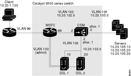
CSM Virtual Servers:
•![]() Client clear text traffic—10.20.102.100:80
Client clear text traffic—10.20.102.100:80
•![]() Client SSL traffic—10.20.102.100:443
Client SSL traffic—10.20.102.100:443
•![]() Decrypted traffic from SSL Services Modules—10.20.103.100:80
Decrypted traffic from SSL Services Modules—10.20.103.100:80
SSL Virtual Servers:
•![]() 10.20.103.110:443
10.20.103.110:443
•![]() 10.20.103.120:443
10.20.103.120:443
In Figure 3-8, VLAN 102, VLAN 103 and VLAN 105 are in separate subnets. VLAN 100 (admin) is set up as a separate VLAN for management purposes.
Add all the required VLANs to the VLAN database, and configure the IP interfaces for VLAN 100 and VLAN 102 on the MSFC. Configure VLANs 102, 103, and 105 on the CSM. See the "Preparing to Configure the SSL Services Module" section for information on how to configure VLANs and IP interfaces.
Note ![]() While VLAN 100 and VLAN 102 exist as Layer 3 interfaces on the MSFC, both VLAN 103 and VLAN 105 exist only as VLANs in the VLAN database and as CSM VLANs, but do not have a corresponding Layer 3 interface on the MSFC.
While VLAN 100 and VLAN 102 exist as Layer 3 interfaces on the MSFC, both VLAN 103 and VLAN 105 exist only as VLANs in the VLAN database and as CSM VLANs, but do not have a corresponding Layer 3 interface on the MSFC.
This example shows how to create the client and server VLANs on the CSM installed in slot number 5:
Router# configure terminal
Enter configuration commands, one per line. End with CNTL/Z.
Router(config)# module csm 5
Router(config-module-csm)# vlan 102 client
Router(config-slb-vlan-client)# ip address 10.20.102.2 255.255.255.0
Router(config-slb-vlan-client)# alias 10.20.102.1 255.255.255.0
Router(config-slb-vlan-client)# gateway 10.20.102.99
Router(config-slb-vlan-client)# exit
Router(config-module-csm)# vlan 103 server
Router(config-slb-vlan-server)# ip address 10.20.103.2 255.255.255.0
Router(config-slb-vlan-server)# alias 10.20.103.1 255.255.255.0
Router(config-slb-vlan-server)# exit
Router(config-module-csm)# vlan 105 server
Router(config-slb-vlan-server)# ip address 10.20.105.2 255.255.255.0
Router(config-slb-vlan-server)# alias 10.20.105.1 255.255.255.0
Router(config-slb-vlan-server)# end
This example shows how to allow VLAN 103 (client VLAN) between the SSL Services Module and the CSM, and VLAN 100 (admin VLAN) between the SSL Services Module and the MSFC:
Cisco IOS
Router(config)# ssl-proxy module 4 allowed-vlan 100,103
Catalyst Operating System Software
Console> (enable) set trunk 4/1 100,103
This example shows how to create the server farm of web servers (configured with server NAT) and the server farm of SSL Services Modules (configured with server NAT):
Router# configure terminal
Enter configuration commands, one per line. End with CNTL/Z.
Router(config)# module csm 5
Router(config-module-csm)# serverfarm SSLFARM
Router(config-slb-sfarm)# nat server
Router(config-slb-sfarm)# real 10.20.103.110
Router(config-slb-real)# inservice
Router(config-slb-real)# real 10.20.103.120
Router(config-slb-real)# inservice
Router(config-slb-real)# exit
Router(config-slb-sfarm)# exit
Router(config-module-csm)# serverfarm WEBSERVERS
Router(config-slb-sfarm)# nat server
Router(config-slb-sfarm)# real 10.20.105.10
Router(config-slb-real)# inservice
Router(config-slb-real)# real 10.20.105.20
Router(config-slb-real)# inservice
Router(config-slb-real)# real 10.20.105.30
Router(config-slb-real)# inservice
Router(config-slb-real)# end
This example shows how to configure the three virtual servers. In this example, the web servers receive requests to port 80 directly from the clients, and decrypted requests to port 81 from the SSL Services Modules (since IP and port translation are configured).
This example also shows how to configure a sticky group to maintain stickiness based on the SSL ID.
Router# configure terminal
Enter configuration commands, one per line. End with CNTL/Z.
Router(config)# module csm 5
Router(config-module-csm)# sticky 100 ssl timeout 30
Router(config-module-csm)# vserver CLEAR_VIP
Router(config-slb-vserver)# virtual 10.20.102.100 tcp www
Router(config-slb-vserver)# vlan 102
Router(config-slb-vserver)# serverfarm WEBSERVERS
Router(config-slb-vserver)# inservice
Router(config-slb-vserver)# exit
Router(config-module-csm)# vserver DECRYPT_VIP
Router(config-slb-vserver)# virtual 10.20.103.100 tcp 81
Router(config-slb-vserver)# vlan 103
Router(config-slb-vserver)# serverfarm WEBSERVERS
Router(config-slb-vserver)# inservice
Router(config-slb-vserver)# exit
Router(config-module-csm)# vserver SSL_VIP
Router(config-slb-vserver)# virtual 10.20.102.100 tcp https
Router(config-slb-vserver)# vlan 102
Router(config-slb-vserver)# serverfarm SSLFARM
Router(config-slb-vserver)# sticky 30 group 100
Router(config-slb-vserver)# inservice
Router(config-slb-vserver)# end
This example shows how to configure the SSL Services Module to communicate with the CSM over VLAN 103 and to communicate with the MSFC over VLAN 100 (admin VLAN):
ssl-proxy# configure terminal
Enter configuration commands, one per line. End with CNTL/Z.
ssl-proxy(config)# ssl-proxy vlan 103
ssl-proxy(config-vlan)# ipaddr 10.20.103.10 255.255.255.0
ssl-proxy(config-vlan)# gateway 10.20.103.1
ssl-proxy(config-vlan)# exit
ssl-proxy(config)# ssl-proxy vlan 100
ssl-proxy(config-vlan)# ipaddr 10.20.100.10 255.255.255.0
ssl-proxy(config-vlan)# gateway 10.20.100.99
ssl-proxy(config-vlan)# admin
ssl-proxy(config-vlan)# end
To complete the configuration, enter the ssl-proxy service command to create a new service on the SSL Services Module (test1). This example shows how to configure a virtual IP address, which acts as a real server for the CSM (since this virtual IP address is required to reply to ARP, the secondary keyword is not entered). The service is configured to send decrypted traffic back to the CSM and to perform NAT on both the destination IP address and the port:
ssl-proxy# configure terminal
Enter configuration commands, one per line. End with CNTL/Z.
ssl-proxy(config)# ssl-proxy service test1
ssl-proxy(config-ssl-proxy)# virtual ipaddr 10.20.103.110 protocol tcp port 443
ssl-proxy(config-ssl-proxy)# server ipaddr 10.20.102.100 protocol tcp port 81
ssl-proxy(config-ssl-proxy)# certificate rsa general-purpose trustpoint testtp
ssl-proxy(config-ssl-proxy)# nat server
ssl-proxy(config-ssl-proxy)# inservice
ssl-proxy(config-ssl-proxy)# end
The following examples show the output of the various show commands on the MSFC and CSM:
Router# show mod csm 5 vlan deta
vlan IP address IP mask type
---------------------------------------------------
102 10.20.102.2 255.255.255.0 CLIENT
GATEWAYS
10.20.102.99
ALIASES
IP address IP mask
--------------------------------
10.20.102.1 255.255.255.0
103 10.20.103.2 255.255.255.0 SERVER
ALIASES
IP address IP mask
--------------------------------
10.20.103.1 255.255.255.0
105 10.20.105.2 255.255.255.0 SERVER
ALIASES
IP address IP mask
--------------------------------
10.20.105.1 255.255.255.0
Router# show mod csm 5 vser deta
CLEAR_VIP, type = SLB, state = OPERATIONAL, v_index = 10
virtual = 10.20.102.100/32:80, TCP, service = NONE, advertise = FALSE
idle = 3600, replicate csrp = none, vlan = 102, pending = 30
max parse len = 600, persist rebalance = TRUE
conns = 0, total conns = 1
Default policy:
server farm = WEBSERVERS, backup = <not assigned>
sticky: timer = 0, subnet = 0.0.0.0, group id = 0
Policy Tot Conn Client pkts Server pkts
-----------------------------------------------------
(default) 1 6 4
DECRYPT_VIP, type = SLB, state = OPERATIONAL, v_index = 11
virtual = 10.20.103.100/32:81, TCP, service = NONE, advertise = FALSE
idle = 3600, replicate csrp = none, vlan = 103, pending = 30
max parse len = 600, persist rebalance = TRUE
conns = 0, total conns = 2
Default policy:
server farm = WEBSERVERS, backup = <not assigned>
sticky: timer = 0, subnet = 0.0.0.0, group id = 0
Policy Tot Conn Client pkts Server pkts
-----------------------------------------------------
(default) 2 11 7
SSL_VIP, type = SLB, state = OPERATIONAL, v_index = 13
virtual = 10.20.102.100/32:443, TCP, service = NONE, advertise = FALSE
idle = 3600, replicate csrp = none, vlan = 102, pending = 30
max parse len = 600, persist rebalance = TRUE
conns = 0, total conns = 2
Default policy:
server farm = SSLFARM, backup = <not assigned>
sticky: timer = 30, subnet = 0.0.0.0, group id = 100
Policy Tot Conn Client pkts Server pkts
-----------------------------------------------------
(default) 2 21 15
The following examples show the output of the various show commands on the SSL Services Module:
ssl-proxy# show ssl-proxy service test1
Service id: 0, bound_service_id: 256
Virtual IP: 10.20.103.110, port: 443
Server IP: 10.20.103.100, port: 81
rsa-general-purpose certificate trustpoint: testtp
Certificate chain in use for new connections:
Server Certificate:
Key Label: testtp
Serial Number: 01
Root CA Certificate:
Serial Number: 00
Certificate chain complete
Admin Status: up
Operation Status: up
ssl-proxy#
ssl-proxy# show ssl-proxy stats
TCP Statistics:
Conns initiated : 2 Conns accepted : 2
Conns established : 4 Conns dropped : 4
Conns closed : 4 SYN timeouts : 0
Idle timeouts : 0 Total pkts sent : 26
Data packets sent : 15 Data bytes sent : 8212
Total Pkts rcvd : 26 Pkts rcvd in seq : 11
Bytes rcvd in seq : 5177
SSL stats:
conns attempted : 2 conns completed : 2
full handshakes : 2 resumed handshakes : 0
active conns : 0 active sessions : 0
renegs attempted : 0 conns in reneg : 0
handshake failures : 0 data failures : 0
fatal alerts rcvd : 0 fatal alerts sent : 0
no-cipher alerts : 0 ver mismatch alerts : 0
no-compress alerts : 0 bad macs received : 0
pad errors : 0
FDU Statistics
IP Frag Drops : 0 Serv_Id Drops : 0
Conn Id Drops : 0 Checksum Drops : 0
IOS Congest Drops : 0 IP Version Drops : 0
Hash Full Drops : 0 Hash Alloc Fails : 0
Flow Creates : 4 Flow Deletes : 4
conn_id allocs : 4 conn_id deallocs : 4
Tagged Drops : 0 Non-Tagged Drops : 0
Add ipcs : 0 Delete ipcs : 0
Disable ipcs : 0 Enable ipcs : 0
Unsolicited ipcs : 0 Duplicate ADD ipcs: 0
Advanced Configuration
This section describes the following advanced configurations:
•![]() Enabling the Cryptographic Self-Test
Enabling the Cryptographic Self-Test
Configuring Policies
See the "Configuring SSL Proxy Services" section for procedures for applying policies to a proxy service.
This section describes how to configure SSL and TCP policies:
Configuring SSL Policy
Note ![]() The SSL commands for the SSL Services Module apply either globally or to a particular proxy server.
The SSL commands for the SSL Services Module apply either globally or to a particular proxy server.
The SSL policy template allows you to define parameters associated with the SSL stack.
If you do not associate an SSL policy with a particular proxy server, the proxy server enables all the supported cipher suites and versions by default.
To define an SSL policy template and associate an SSL policy with a particular proxy server, perform this task:
Configuring TCP Policy
Note ![]() The TCP commands for the SSL Services Module apply either globally or to a particular proxy server.
The TCP commands for the SSL Services Module apply either globally or to a particular proxy server.
The TCP policy template allows you to define parameters associated with the TCP stack.
To define an TCP policy template and associate an TCP policy with a particular proxy server, perform this task:
|
|
|
|
|---|---|---|
Step 1 |
ssl-proxy (config)# ssl-proxy policy tcp tcp_policy_name |
Defines TCP policy templates. All defaults are assumed unless otherwise specified. |
Step 2 |
ssl-proxy (config-ssl-policy)# mss max_segment_size |
Configures the maximum segment size (MSS), in bytes, that the connection will identify in the SYN packet that it generates. Note |
Step 3 |
ssl-proxy (config-ssl-policy)# timeout syn time |
Configures the connection establishment timeout. The default is 75 seconds. The valid range is from 5 to 75 seconds. |
Step 4 |
ssl-proxy (config-ssl-policy)# timeout inactivity time |
Configures the inactivity timeout in seconds. This timeout determines the aging timeout for an idle connection. The default is from 600 seconds. The valid range is 0 to 960 seconds (0 = no timeout). |
Step 5 |
ssl-proxy (config-ssl-policy)# timeout fin-wait time |
Configures the FIN wait timeout in seconds. The default value is 600 seconds. The valid range is from 75 to 600 seconds. |
Step 6 |
ssl-proxy (config-ssl-policy)# buffer-share rx buffer_limit |
Allows you to configure the maximum receive buffer share per connection in bytes. The default value is 32768 bytes. The valid range is from 8192 to 262144 bytes. |
Step 7 |
ssl-proxy (config-ssl-policy)# buffer-share tx buffer_limit |
Allows you to configure the maximum transmit buffer share per connection in bytes. The default value is 32768 bytes. The valid range is from 8192 to 262144 bytes. |
1 If fragmentation occurs, decrease the MSS value until there is no fragmentation. |
Configuring NAT
Client connections originate from the client and are terminated on the SSL Services Module. Server connections originate from the SSL Services Module.
You can configure client NAT, server NAT, or both, on the server connection.
Server NAT
The server IP address configured with the ssl-proxy service command specifies the IP address and port for the destination device, either the CSM or the real server for which the SSL Services Module acts as a proxy. If you configure server NAT, the server IP address is used as the destination IP address for the server connection. If the server NAT is not configured, the destination IP address for the server connection is the same as the virtual ipaddress for which SSL Services Module is a proxy. The SSL Services Module always performs the port translation by using the port number entered in the server ipaddress subcommand.
To configure server NAT, enter the nat server subcommand under the ssl-proxy service command:
Client NAT
If you configure client NAT, the server connection source IP address and port are derived from a NAT pool. If client NAT is not configured, the server connection source IP address and port are derived from the source IP address and source port of the client connection.
Allocate enough IP addresses to satisfy the total number of connections supported by the SSL Services Module (256,000 connections). Assuming you have 32,000 ports per IP address, configure 8 IP addresses in the NAT pool. If you try to configure fewer IP addresses than required by the total connections supported by the SSL Services Module, the command is rejected.
To configure a NAT pool and assign the NAT pool to the proxy service, perform this task:
Enabling the Cryptographic Self-Test
Note ![]() The power-on crypto chip self-test and key test are run only once at bootup.
The power-on crypto chip self-test and key test are run only once at bootup.
Note ![]() Use the self-test for troubleshooting only. Running this test will impact run-time performance.
Use the self-test for troubleshooting only. Running this test will impact run-time performance.
To run the self-test, perform this task:
This example shows how to enable the cryptographic self-test and display cryptographic information:
ssl-proxy(config)# ssl-proxy crypto self-test time-interval 1
ssl-proxy(config)# end
ssl-proxy# show ssl-proxy stats crypto
Crypto Statistics from SSL Module:1
Self-test is running
Current device index is 1
Time interval between tests is 1 seconds
Device 0 statistics:
Total Number of runs:50
Runs all passed:50
Number of timer error:0
---------------------------------------------------------
Test Name Passed Failed Did-not-run
---------------------------------------------------------
0 Power-on Crypto chip sel 1 0 0
1 Power-on Crypto chip key 1 0 0
2 Hash Test Case 1 50 0 0
3 Hash Test Case 2 50 0 0
4 Hash Test Case 3 50 0 0
5 Hash Test Case 4 50 0 0
6 SSL3 MAC Test Case 1 50 0 0
7 SSL3 MAC Test Case 2 50 0 0
8 TLS1 MAC Test Case 1 50 0 0
9 TLS1 MAC Test Case 2 50 0 0
10 DES Server Test 50 0 0
11 DES Encrypt Test 1 50 0 0
12 DES Decrypt Test 1 50 0 0
13 DES Encrypt Test 2 50 0 0
14 DES Decrypt Test 2 50 0 0
15 ARC4 Test Case 1 50 0 0
16 ARC4 Test Case 2 50 0 0
17 ARC4 Test Case 3 50 0 0
18 ARC4 State Test Case 1 50 0 0
19 ARC4 State Test Case 2 50 0 0
20 ARC4 State Test Case 3 50 0 0
21 ARC4 State Test Case 4 50 0 0
22 HMAC Test Case 1 50 0 0
23 HMAC Test Case 2 50 0 0
24 Random Bytes Generation 50 0 0
25 RSA Encrypt/Decrypt Test 50 0 0
26 Master Secret Generation 50 0 0
27 Key Material Generation 50 0 0
28 SSL3 Handshake Hash Test 50 0 0
29 TLS1 Handshake Hash Test 50 0 0
Device 1 statistics:
Total Number of runs:49
Runs all passed:49
Number of timer error:0
---------------------------------------------------------
Test Name Passed Failed Did-not-run
---------------------------------------------------------
0 Power-on Crypto chip sel 1 0 0
1 Power-on Crypto chip key 1 0 0
2 Hash Test Case 1 50 0 0
3 Hash Test Case 2 50 0 0
4 Hash Test Case 3 50 0 0
5 Hash Test Case 4 50 0 0
6 SSL3 MAC Test Case 1 50 0 0
7 SSL3 MAC Test Case 2 50 0 0
8 TLS1 MAC Test Case 1 50 0 0
9 TLS1 MAC Test Case 2 50 0 0
10 DES Server Test 50 0 0
11 DES Encrypt Test 1 50 0 0
12 DES Decrypt Test 1 50 0 0
13 DES Encrypt Test 2 50 0 0
14 DES Decrypt Test 2 50 0 0
15 ARC4 Test Case 1 50 0 0
16 ARC4 Test Case 2 50 0 0
17 ARC4 Test Case 3 50 0 0
18 ARC4 State Test Case 1 49 0 0
19 ARC4 State Test Case 2 49 0 0
20 ARC4 State Test Case 3 49 0 0
21 ARC4 State Test Case 4 49 0 0
22 HMAC Test Case 1 49 0 0
23 HMAC Test Case 2 49 0 0
24 Random Bytes Generation 49 0 0
25 RSA Encrypt/Decrypt Test 49 0 0
26 Master Secret Generation 49 0 0
27 Key Material Generation 49 0 0
28 SSL3 Handshake Hash Test 49 0 0
29 TLS1 Handshake Hash Test 49 0 0
This example shows how to display PKI information:
ssl-proxy# show ssl-proxy stats pki
PKI Memory Usage Counters:
Malloc count:252
Setstring count:46
Free count:222
Malloc failed:0
Ipc alloc count:56
Ipc free count:84
Ipc alloc failed:0
PKI IPC Counters:
Request buffer sent:28
Request buffer received:0
Request duplicated:0
Request send failed:0
Response buffer sent:0
Response buffer received:28
Response timeout:0
Response failed:0
Response with error reported by SSL Processor:0
Response with no request:0
Response duplicated:0
Message type error:0
Message length error:0
Key Certificate Table Current Usage (cannot be cleared):
Total number of entries in table:8192
Entries in use:7
Free entries:8185
Complete server entries:5
Incomplete new/renew server entries:1
Retiring server entries:0
Obsolete server entries:0
Complete intermediate CA cert:0
Complete root CA cert:1
Obsolete intermediate CA cert:0
Obsolete root CA cert:0
PKI Accumulative Counters (cannot be cleared):
Proxy service trustpoint added:7
Proxy service trustpoint deleted:1
Proxy service trustpoint modified:0
Keypair added:6
Keypair deleted:1
Wrong key type:1
Server certificate added:6
Server certificate deleted:1
Server certificate rolled over:0
Server certificate completed:6
Intermediate CA certificate added:0
Intermediate CA certificate deleted:0
Root CA certificate added:1
Root CA certificate deleted:0
Certificate overwritten:0
No free table entries:0
Rollover failed:0
History records written:4
History records currently kept in memory:4
History records have been cleared:0 times
ssl-proxy#
Collecting Crash Information
The crash-info feature collects information necessary for developers to fix software-forced resets. Enter the show ssl-proxy crash-info command to collect software-forced reset information. You can retrieve only the latest crash-info in case of multiple software-forced resets. The show ssl-proxy crash-info command takes 1 to 6 minutes to complete the information collection process.
Note ![]() The show stack command is not a supported command to collect software-forced reset information on the SSL Service Module.
The show stack command is not a supported command to collect software-forced reset information on the SSL Service Module.
The following example shows how to collect software-forced reset information:
ssl-proxy# show ssl-proxy crash-info
===== SSL SERVICE MODULE - START OF CRASHINFO COLLECTION =====
------------- COMPLEX 0 [FDU_IOS] ----------------------
NVRAM CHKSUM:0xB562
NVRAM MAGIC:0xC8A514F0
++++++++++ CORE 0 ++++++++++++++++++++++++++++++++++
-> CID:1 (IOS)
-> APPLICATION VERSION:
-> APPROXIMATE TIME:00:00:00 UTC Jan 1 1970
-> GENUINE:3391429263 This core has crashed
-> TRACEBACK:DDBE3FEF 887090E7 222DA8
-> CPU CONTEXT -----------------------------
$0 :00000000, AT :00000000, v0 :00260000, v1 :37EF9598
a0 :00000001, a1 :00000001, a2 :0000003C, a3 :00233280
t0 :002474C4, t1 :00000004, t2 :00000000, t3 :00000001
t4 :00000010, t5 :00000001, t6 :00000001, t7 :00000001
s0 :00000000, s1 :004C4B3F, s2 :002474CC, s3 :00000000
s4 :00000000, s5 :0000003C, s6 :0000003C, s7 :00000019
t8 :0000000F, t9 :00000000, k0 :00000100, k1 :00400001
gp :00000000, sp :0023AEC0, s8 :031FFF58, ra :00000064
LO :00000000, HI :00000000, BADVADDR :0000000C
EPC :00000000, ErrorEPC :00222DA8, SREG :00000000
Cause 27299127 (Code 0x9):Breakpoint exception
-> PROCESS STACK -----------------------------
-> stack top:0x0
Process stack in use ( sp -> stack_top ):
-> sp out of recorded stack area. Stack bottom:0xFFFFC000
0023AEB4: 00000000 ....
0023AEC4:03200000 02B01021 26440A30 0C197B99 . ...0.!&D.0..{.
0023AED4:90450000 26020001 30420003 14400004 .E..&...0B...@..
...........
...........
...........
FFFFFFD0:00000000 00000000 00000000 00000000 ................
FFFFFFE0:00627E34 00000000 00000000 00000000 .b~4............
FFFFFFF0:00000000 00000000 00000000 00000006 ................
00000000:
===== SSL SERVICE MODULE - END OF CRASHINFO COLLECTION =======
Enabling VTS Debugging
A virtual terminal server (VTS) is built into the SSL Service Module for debugging different processors (FDU, TCP, SSL) on the module.
Note ![]() Use the TCP debug commands only to troubleshoot basic connectivity issues under little or no load conditions (for instance, when no connection is being established to the virtual server or real server).
Use the TCP debug commands only to troubleshoot basic connectivity issues under little or no load conditions (for instance, when no connection is being established to the virtual server or real server).
If you use TCP debug commands, the TCP module displays large amounts of debug information on the console, which can significantly slow down module performance. Slow module performance can lead to delayed processing of TCP connection timers, packets, and state transitions.
From a workstation or PC, make a Telnet connection to one of the module's VLAN IP addresses to reach the FDU (port 2001), TCP (port 2002), and SSL (port 2003) processor on the SSL Services Module.
To display debugging information, perform this task:
|
|
|
|---|---|
ssl-proxy# [no] debug ssl-proxy {fdu |
ssl | tcp} [type]
|
Turns on or off the debug flags for the specified system component. |
After you make the Telnet connection, enter the debug ssl-proxy {tcp | fdu | ssl} command from the SSL Services Module console. One connection is sent from a client and displays the logs found in TCP console.
The following example shows how to display the log for TCP states for a connection and verify the debugging state:
ssl-proxy# debug ssl-proxy tcp state
ssl-proxy# show debugging
STE Mgr:
STE TCP states debugging is on
The following example shows the output from the workstation or PC:
Conn 65066 state CLOSED --> state SYN_RECEIVED
Conn 65066 state SYN_RECEIVED --> state ESTABLISHED
Conn 14711 state CLOSED --> state SYN_SENT
Conn 14711 state SYN_SENT --> state ESTABLISHED
Conn 14711 state ESTABLISHED --> state CLOSE_WAIT
Conn 65066 state ESTABLISHED --> state FIN_WAIT_1
Conn 65066 state FIN_WAIT_1 --> state FIN_WAIT_2
Conn 65066 state FIN_WAIT_2 --> state TIME_WAIT
Conn 14711 state CLOSE_WAIT --> state LAST_ACK
Conn 14711 state LAST_ACK --> state CLOSED
##############Conn 65066 state TIME_WAIT --> state CLOSED
 Feedback