Cisco HyperFlex Systems Installation Guide for VMware ESXi, Release 4.5
Bias-Free Language
The documentation set for this product strives to use bias-free language. For the purposes of this documentation set, bias-free is defined as language that does not imply discrimination based on age, disability, gender, racial identity, ethnic identity, sexual orientation, socioeconomic status, and intersectionality. Exceptions may be present in the documentation due to language that is hardcoded in the user interfaces of the product software, language used based on RFP documentation, or language that is used by a referenced third-party product. Learn more about how Cisco is using Inclusive Language.
6200/6400/6500 series FI: Use at least two 10-Gb Small Form-Factor Pluggable (SFP) cables per server.
6300 series FI: Use at least two 40-GbE QSFP cables per server.
Ensure that the Fabric Interconnect console cable (CAB-CONSOLE-RJ45) has an RJ-45 connector on one end and a DB9 connector
on the other. This cable is used to connect into the RS-232 console connection on a laptop.
Ensure that the standard power cords have an IEC C13 connector on the end that plugs into the power supplies. Make sure that
the optional jumper power cords have an IEC C13 connector on the end that plugs into the power supplies and an IEC C14 connector
on the end that plugs into an IEC C13 outlet receptacle.
The KVM cable provides a connection for the Cisco HX-Series Servers into the system. It has a DB9 serial connector, a VGA
connector for a monitor, and dual USB 2.0 ports for a keyboard and mouse. With this cable, you can create a direct connection
to the operating system and the BIOS running on the system.
Note
This same KVM cable is used for both UCS rack mount and blade servers.
A Cisco HyperFlex cluster contains a minimum of three converged HyperFlex nodes. There is an option of adding compute-only
nodes to provide additional compute power if there is no need for extra storage. Each server in a HyperFlex cluster is also
referred as a HyperFlex node. Make sure that each node has the following settings installed and configured before you deploy
the storage cluster.
Ensure that the following host requirements are met.
Use the same VLAN IDs for all the servers (node or hosts) in the cluster.
Use the same administrator login credentials for all the ESXi servers across the storage cluster.
Note
The root user is created with the same password as the admin user during cluster creation. It is important to track the root
user password because future changes to the admin password do not automatically update the root password .
The disk requirements vary between converged nodes and compute-only nodes. To increase the available CPU and memory capacity,
you can expand the existing cluster with compute-only nodes as needed. These compute-only nodes provide no increase to storage
performance or storage capacity.
Alternatively, adding converged nodes increase storage performance and storage capacity alongside CPU and memory resources.
Servers with only Solid-State Disks (SSDs) are All-Flash servers. Servers with both SSDs and Hard Disk Drives (HDDs) are hybrid
servers.
The following applies to all the disks in a HyperFlex cluster:
All the disks in the storage cluster must have the same amount of storage capacity. All the nodes in the storage cluster must
have the same number of disks.
All SSDs must support TRIM and have TRIM enabled.
All HDDs can be either SATA or SAS type. All SAS disks in the storage cluster must be in a pass-through mode.
Disk partitions must be removed from SSDs and HDDs. Disks with partitions are ignored and not added to your HX storage cluster.
Moving operational disks between servers within same cluster or moving them into expansion nodes within the same active cluster
is not supported.
Optionally, you can remove or backup existing data on disks. All existing data on a provided disk is overwritten.
Note
New factory servers are shipped with appropriate disk partition settings. Do not remove disk partitions from new factory servers.
Only the disks ordered directly from Cisco are supported.
On servers with Self Encrypting Drives (SED), both the cache and persistent storage (capacity) drives must be SED capable.
These servers support Data at Rest Encryption (DARE).
In the event you see an error about unsupported drives or catalog upgrade, see the Compatibility Catalog.
In addition to the disks listed in the table below, all M4 converged nodes have 2 x 64-GB SD FlexFlash cards in a mirrored
configuration with ESX installed. All M5 converged nodes have M.2 SATA SSD with ESXi installed.
Note
Do not mix storage disks type or storage size on a server or across the storage cluster. Mixing storage disk types is not
supported.
When replacing cache or persistent disks, always use the same type and size as the original disk.
Do not mix any of the persistent drives. Use all HDD or SSD and the same size drives in a server.
Do not mix hybrid and All-Flash cache drive types. Use the hybrid cache device on hybrid servers and All-Flash cache devices
on All-Flash servers.
Do not mix encrypted and non-encrypted drive types. Use SED hybrid or SED All-Flash drives. On SED servers, both the cache
and persistent drives must be SED type.
All nodes must use same size and quantity of SSDs. Do not mix SSD types.
Please refer to the corresponding server model spec sheet for details of drives capacities and number of drives supported
on the different servers.
For information on compatible PIDs when performing an expansion of existing cluster, please refer to the Cisco HyperFlex Drive Compatibility document.
Compute-Only Nodes
The following table lists the supported compute-only node configurations for compute-only functions. Storage on compute-only
nodes is not included in the cache or capacity of storage clusters.
Note
When adding compute nodes to your HyperFlex cluster, the compute-only service profile template automatically configures it
for booting from an SD card. If you are using another form of boot media, update the local disk configuration policy. See
the Cisco UCS Manager Server Management Guide for server-related policies.
Supported Compute-Only Node Servers
Supported Methods for Booting ESXi
Cisco B200 M4/M5
B260 M4
B420 M4
B460 M4
C240 M4/M5
C220 M4/M5
C460 M4
C480 M5
B480 M5
Choose any method.
Important
Ensure that only one form of boot media is exposed to the server for ESXi installation. Post install, you may add in additional
local or remote disks.
USB boot is not supported for HX Compute-only nodes.
SD Cards in a mirrored configuration with ESXi installed.
Local drive HDD or SSD.
SAN boot.
M.2 SATA SSD Drive.
Note
HW RAID M.2 (UCS-M2-HWRAID and HX-M2-HWRAID) is a supported boot configuration starting with HX Data Platform release 4.5(1a)
and later.
Port Requirements
If your network is behind a firewall, in addition to the standard port requirements, VMware recommends ports for VMware ESXi
and VMware vCenter.
CIP-M is for the cluster management IP.
SCVM is the management IP for the controller VM.
ESXi is the management IP for the hypervisor.
The comprehensive list of ports required for component communication for the HyperFlex solution is located in Appendix A of
the HX Data Platform Security Hardening Guide
Tip
If you do not have standard configurations and need different port settings, refer to Appendix A of the HX Data Platform Security Hardening Guide for customizing your environment.
HyperFlex External Connections
External Connection
Description
IP Address/ FQDN/ Ports/Version
Essential Information
Intersight Device Connector
Supported HX systems are connected to Cisco Intersight through a device connector that is embedded in the management controller
of each system.
HTTPS Port Number: 443
1.0.5-2084 or later (Auto-upgraded by Cisco Intersight)
All device connectors must properly resolve
svc.intersight.com and allow
outbound-initiated HTTPS connections on port 443.
The current HX Installer supports the use of an
HTTP proxy.
The IP addresses of ESXi management must be
reachable from Cisco UCS Manager over all the
ports that are listed as being needed from
installer to ESXi management, to ensure deployment
of ESXi management from Cisco Intersight.
Note
Outbound HTTPS connections on port 443
initiated by ESXi hosts can be blocked by the
default ESXi firewall. The ESXi firewall can be
temporarily disabled to allow this
connectivity.
To disable the ESXi firewall, use the
esxcli network firewall set
                                                         --enabled=false
command and after the
installation has completed use the esxcli
network firewall set --enabled=false
command to re-enable the firewall.
Auto Support (ASUP) is the alert notification service provided through HX Data Platform.
SMTP Port Number: 25
Enabling Auto Support is strongly recommended because it provides historical hardware counters that are valuable in diagnosing
future hardware issues, such as a drive failure for a node.
Fabric Interconnect
Uplink Provisioning
Prior to setting up the HyperFlex cluster, plan the upstream bandwidth capacity for optimal network traffic management. This
ensures that the flow is in steady state, even if there is a component failure or a partial network outage.
By default, the hx-vm-network vSwitch is configured as active/active. All other vSwitches are configured as active/standby.
Note
All VLANs (including storage-data and vmotion) must be configured upstream. It is imperative that storage-data is configured
upstream to prevent fail-back timing issues which require temporary upstream connectivity.
Note
For clusters running Catalyst switches upstream to the FI's, set the best effort Quality of Service (QOS) MTU to 9216 (located
in LAN > LAN Cloud > QoS System Class), otherwise failover will fail.
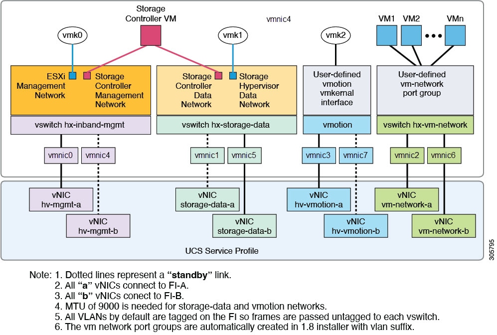
Figure 1. HyperFlex Data Platform Connectivity for a Single Host
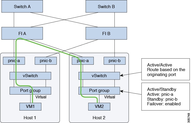
Set the default vSwitch NIC teaming policy and failover policy to yes to ensure that all management, vMotion, and storage traffic are locally forwarded to the fabric interconnects to keep the
flow in steady state. When vNIC-a fails, ESXi computes the load balancing and all the virtual ports are repinned to vNIC-b.
When vNIC-a comes back online, repinning does apply and virtual ports are rebalanced across vNIC-a and vNIC-b. This reduces
the latency and bandwidth utilization upstream of the Cisco UCS fabric interconnects.
Figure 2. Traffic Flow in Steady State
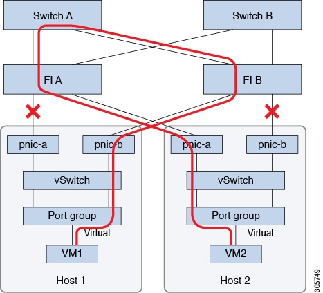
In case one or more server links fail, for instance, if Host 1 loses connectivity to Fabric A while Host 2 loses connectivity
to Fabric B, the traffic must go through the upstream switches. Therefore, the uplink network bandwidth usage increases, and
you must add more uplinks.
Figure 3. Traffic Flow During Link Failure
Note
When you have uplinks from a fabric interconnect to two different upstream switches, you encounter a condition called Disjoint Layer 2 (DJL2) on the FI. This is known to happen on the FI on End Host Mode and if the DJL2 is not configured properly.
All IP addresses must be IPv4. HyperFlex does not support IPv6 addresses.
Note
You cannot use the storage-data VLAN for User VM traffic.
Best Practices
Must use different subnets and VLANs for each network.
Directly attach each host to a Cisco UCS fabric interconnect using a 10-Gbps cable.
Do not use VLAN 1 which is the default VLAN as it can cause networking issues, especially if Disjoint Layer 2 configuration
is used.
Installer sets the VLANs as non-native by default. Ensure to configure the upstream switches to accommodate the non-native VLANs.
Uplinks from the UCS Fabric Interconnects to all top of rack switch ports need to hahve Port-fast, spanning-tree port type
edge trunk, or similar spanning tree configuration that immediately put ports into forwarding mode. Configure spanning tree
in edge trunk or portfast edge mode depending on the vendor and model of the switch. This extra configuration ensures that when links flap or change state,
they do not transition through unnecessary spanning tree states and incur an extra delay before traffic forwarding begins.
Failure to properly configure FI uplinks in portfast edge mode may result in network and cluster outages during failure scenarios and during infrastructure upgrades that leverage
the highly available network design native to HyperFlex.
Each ESXi host needs the following networks.
Management traffic network—From the vCenter, handles the hypervisor (ESXi server) management, and storage cluster management.
Data traffic network— Handles the hypervisor and storage data traffic and is required to be a unique VLAN per Hyperflex Cluster.
vMotion network
VM network
There are four vSwitches, each carrying a different network.
vswitch-hx-inband-mgmt—Used for ESXi management, storage controller management, and Replication. These two vSwitches are further divided in two
port groups with assigned static IP addresses to handle traffic between the storage cluster and the ESXi host.
vswitch-hx-storage-data—Used for ESXi storage data and HX Data Platform ISCSI. These two vSwitches are further divided in two port groups with assigned
static IP addresses to handle traffic between the storage cluster and the ESXi host. These two vSwitches are further divided
in two port groups with assigned static IP addresses to handle traffic between the storage cluster and the ESXi host.
vswitch-hx-vmotion—Used for VM and storage vMotion.
This vSwitch, has one port group for management, defined through vSphere that connects to all the hosts in the vCenter cluster.
The Cisco HX Data Platform Installer automatically creates the vSwitches.
The following services in vSphere must be enabled after the HyperFlex storage cluster is created.
DRS (Optional, if licensed)
vMotion
High Availability
VLAN and vSwitch Requirements
Provide at least three VLAN IDs.
All VLANs must be configured on the fabric interconnects during the installation.
All VLANs (including storage-data and vmotion) must be configured upstream. It is imperative that storage-data is configured
upstream to prevent fail-back timing issues which require temporary upstream connectivity.
VLAN Type
Description
Note
Must use different subnets and VLANs for each of the following networks.
VLAN ESXi and HyperFlex Management Traffic
VLAN Name: <user-defined> (for example "hx-inband-mgmt")
VLAN ID: <user-defined>
VLAN HyperFlex Storage Data
VLAN Name: <user-defined> (for example, "hx-storage-data")
VLAN VM Network: <user-defined> (for example, "hx-vm-network"). This is required to be a unique VLAN HyperFlex Cluster.
VLAN ID: <user-defined>
The VLAN tagging with External Switch VLAN Tagging (EST) and vSwitch settings are applied using UCS Manager profiles. The
HX Data Platform Installer, simplifies this process.
Note
Do not use VLAN 1 which is the default VLAN as it can cause networking issues, especially if Disjoint Layer 2 configuration
is used. Use a different VLAN other than VLAN 1.
Installer sets the VLANs as non-native by default. Configure the upstream switches to accommodate the non-native VLANs.
Inband Management is not supported on VLAN 2 or VLAN 3.
Cisco UCS Requirements
Provide the listed content for the UCS Fabric Interconnect and UCS Manager when prompted.
Cisco UCS Fabric Interconnect Requirements
UI Element
Essential Information
Uplink Switch Model
Provide the switch type and connection type (SFP + Twin Ax or Optic).
Fabric Interconnect Cluster IP address
<IP address>.
FI-A IP Address
<IP address>.
FI-B IP Address
<IP address>.
MAC Address Pool
Check 00:00:00 MAC address pool.
IP Blocks
KVM IP pool. A minimum of 4 IP addresses.
Subnet mask
For example, 255.255.0.0.
Default Gateway
For example, 10.193.0.1.
Cisco UCS Manager Requirements
UI Element
Essential Information
UCS Manager Host Name
Hostname or IP address.
User Name
<admin username>
Password
<admin username>
Hypervisor
Requirements
Enter the IP address from the range of addresses that are available to the ESXi servers on the storage management network
or storage data network through vCenter. Provide static IP addresses for all network addresses.
Note
Data and Management networks must be on different subnets.
Data network IP addresses cannot be changed after the storage cluster is created. Contact Cisco TAC for assistance changing
Management Network IPs.
Though, not required by itself, if you are specifying DNS names, enable IP addresses forward and reverse DNS lookup.
The installer IP address must be reachable from the management subnet used by the hypervisor and the storage controller VMs.
The installer appliance must run on the ESXi host or on a VMware workstation that is not a part of the cluster to be installed.
Management
Network IP Addresses
Data
Network IP Addresses
Hypervisor
Storage Controller
Hypervisor
Storage Controller
<IP Address >
<IP Address >
<IP Address >
<IP Address >
<IP Address >
<IP Address >
<IP Address >
<IP Address >
<IP Address >
<IP Address >
<IP Address >
<IP Address >
<IP Address >
<IP Address >
<IP Address >
<IP Address >
VLAN Tag
VLAN_ID
VLAN Tag
VLAN_ID
Subnet Mask
Subnet Mask
Default Gateway
Default Gateway
Installer Appliance IP Addresses
<IP Address >
<IP Address >
Storage Cluster
Requirements
Storage cluster is a component of the Cisco HX Data Platform which reduces storage complexity by providing a single datastore
that is easily provisioned in the vSphere Web Client. Data is fully distributed across disks in all the servers that are in
the storage cluster, to leverage controller resources and provide high availability.
A storage cluster is independent of the associated vCenter cluster. You can create a storage cluster using ESXi hosts that
are in the vCenter cluster.
To define the storage cluster, provide the following parameters.
Field
Description
Name
Enter a name for the storage cluster.
Management IP Address
This provides the storage management network, access on each ESXi host.
The IP address must be on the same subnet as the Management IP addresses for the nodes.
Do not allow cluster management IPs to share the last octet with another cluster on the same subnet.
These IP addresses are in addition to the four IP addresses we assign to each node in the Hypervisor section.
Storage Cluster Data IP Address
This provides the storage data network and storage controller VM network, access on each ESXi host.
The same IP address must be applied to all ESXi nodes in the cluster.
Data Replication Factor
Data Replication Factor defines the number of redundant replicas of your data across the storage cluster.
This is set during HX Data Platform installation and cannot be changed.
Choose a Data Replication Factor. The choices are:
Data Replication Factor3—A replication factor of three is highly recommended for all environments except HyperFlex Edge. A replication factor of two
has a lower level of availability and resiliency. The risk of outage due to component or node failures should be mitigated
by having active and regular backups.
Attention
This is the recommended option.
Data Replication Factor2—Keep two redundant replicas of the data. This consumes less storage resources, but reduces your data protection in the event
of simultaneous node or disk failure.
If nodes or disks in the storage cluster fail, the cluster's ability to function is affected. If more than one node fails
or one node and disk(s) on a different node fail, it is called a simultaneous failure.
vCenter Configuration Requirements
Provide administrator level account and password for vCenter. Ensure that you have an existing vCenter server. Ensure that
the following vSphere services are operational.
Enable Dynamic Resource Scheduler (DRS) [Optional, enable if licensed].
Enable vMotion.
Enable High availability (HA) [Required to define failover capacity and for expanding the datastore heartbeat].
User VMs must be version 9 or later [Required to use HX Data Platform, Native Snapshots, and ReadyClones].
Field
Description
vCenter Server
Enter your current vCenter server web address.
For example, http://<IP address>.
User Name
Enter <admin username>.
Password
Enter <admin password>.
Datacenter Name
Note
An existing datacenter object can be used. If the datacenter doesn't exist in vCenter, it will be created.
Enter the required name for the vCenter datacenter.
Cluster Name
Enter the required name for the vCenter cluster. The cluster must contain a minimum of three ESXi servers.
System Services Requirements
Before installing Cisco HX Data Platform, ensure that the following network connections and services are operational.
DNS server
Caution
DNS servers should reside outside of the HX storage cluster. Nested DNS servers can cause a cluster to not start after entire
cluster is shutdown, such as during DC power loss.
NTP server
Caution
NTP servers should reside outside of the HX storage cluster. Nested NTP servers can cause a cluster to not start after entire
cluster is shutdown, such as during DC power loss.
Note
Before configuring the storage cluster, manually verify that the NTP server is working and providing a reliable source for
the time.
Use the same NTP server for all nodes (both converged and compute) and all storage controller VMs.
The NTP server must be stable, continuous (for the lifetime of the cluster), and reachable through a static IP address.
If you are using Active Directory as an NTP server, please make sure that the NTP server is setup according to Microsoft best
practices. For more information, see Windows Time Service Tools and Settings. Please note that if the NTP server is not set correctly, time sync may not work, and you may need to fix the time sync on
the client-side. For more information, see Synchronizing ESXi/ESX time with a Microsoft Domain Controller.
Time Zone
Field
Essential Information
DNS Server(s)
<IP address>
DNS server address is required if you are using hostnames while installing the HyperFlex Data Platform.
Note
If you do not have a DNS server, do not enter a hostname under System Services in the Cluster Configuration page of the HX Data Platform Installer. Use only IP addresses.
To provide more than one DNS servers address, separate the address with a comma. Check carefully to ensure that DNS server addresses are entered correctly.
NTP Server(s)
(A reliable NTP server is required)
<IP address>
NTP server is used for clock synchronization between:
Storage controller VM
ESXi hosts
vCenter server
Important
Static IP address for an NTP server is required to ensure clock synchronization between the storage controller VM, ESXi hosts,
and vCenter server.
During installation, this information is propagated to all the storage controller VMs and corresponding hosts. The servers
are automatically synchronized on storage cluster startup.
Time Zone
<your time zone>
Select a time zone for the storage controller VMs. It is used to determine when to take scheduled snapshots.
Note
All the VMs must be in the same time zone.
CPU Resource
Reservation for Controller VMs
As the storage controller VMs provide critical functionality for the HyperFlex Data Platform, the HX Data Platform Installer
configures CPU resource reservations for the controller VMs. This reservation guarantees that the controller VMs have the
minimum required CPU resources. This is useful in situations where the physical CPU resources of the ESXi hypervisor host
are heavily consumed by the guest VMs. The following table details the CPU resource reservation for storage controller VMs.
Product ID
Number of VM CPU
Shares
Reservation
Limit
HXAF220c-M5SN (All NVMe 220)
12
Low
10,800 MHz
Unlimited
With HX Boost Mode enabled:
HXAF220c-M5SN/HXAF220c-M6SN
16
Low
10,800 MHz
Unlimited
With HX Boost Mode enabled:
HXAF220c-M4/M5/M6
HXAF240c-M4/M5SX/M6
12
Low
10,800 MHz
Unlimited
All Other Models
8
Low
10,800 MHz
Unlimited
Note
Enabling HX Boost Mode does not change the controller VM CPU reservation. It merely changes the upper limit on how much CPU
the controller VM can consume.
Memory Usage for Controller VMs - NVMe Drives
The following table details the memory usage for storage controller VMs for NVMe drives.
Table 2. Memory Usage for Controller VMs - NVMe Drives
Server Model
Drive Size
1 / 4 TB
8 TB
15 TB (HX Release 5.0(2a) and later)
M5 C220 All NVMe
72 GB
84 GB
No Support
M6 C220 All NVMe
72 GB
84 GB
96 GB
M6 240C All NVMe
72 GB
84 GB
110 GB
15 TB persistent drives on All Flash configurations is not supported.
Support for 16 TB LFF drives is not enabled.
Auto Support Requirements
Auto Support (ASUP) is the alert notification service provided through HX Data Platform. If you enable Auto Support, notifications
are sent from HX Data Platform to designated email addresses or email aliases that you want to receive the notifications.
To configure Auto Support, you need the following information:
Auto Support
Enable Auto Support check box
Check this box during HX storage cluster creation.
Mail Server
<IP address>
SMTP mail server must be configured in your network to enable Auto Support. Used for handling email sent from all the storage
controller VM IP addresses.
Note
Only unauthenticated SMTP is supported for ASUP.
Mail Sender
<username@domain.com>
Email address to use for sending Auto Support notifications.
ASUP Recipient
List of email addresses or email aliases to receive Auto Support notifications.
Note
Enabling Auto Support is strongly recommended because it provides historical hardware counters that are valuable in diagnosing
future hardware issues, such as drive failure for a node.
Single Sign On Requirements
The SSO URL is provided by vCenter. If it is not directly reachable from the controller VM, then configure the location explicitly
using Installer Advanced Settings.
Single Sign On (SSO)
SSO Server URL
SSO URL can be found in vCenter at vCenter Server > Manage > Advanced Settings, key config.vpxd.sso.sts.uri


 Feedback