Cisco VXLAN Multi-Site and Service Node Integration
Available Languages
Bias-Free Language
The documentation set for this product strives to use bias-free language. For the purposes of this documentation set, bias-free is defined as language that does not imply discrimination based on age, disability, gender, racial identity, ethnic identity, sexual orientation, socioeconomic status, and intersectionality. Exceptions may be present in the documentation due to language that is hardcoded in the user interfaces of the product software, language used based on RFP documentation, or language that is used by a referenced third-party product. Learn more about how Cisco is using Inclusive Language.
- US/Canada 800-553-2447
- Worldwide Support Phone Numbers
- All Tools
 Feedback
 Feedback
| Description |
|
| January 29, 2024 |
First release of this document. |
Introduction
Executive Summary
The goal of this paper is to cover the design and deployment considerations for integrating service devices (such as firewalls) in a VXLAN EVPN Multi-Site architecture interconnecting multiple VXLAN EVPN fabrics. Different design options are possible, depending on the chosen service device redundancy model (Active/Standby stretched cluster, Active/Active stretched cluster, independent service nodes in each fabric) and on how the service devices need to be integrated to enforce policy for communication between endpoints connected to the fabrics (East-West traffic flows) or between endpoints and external resources (North-South flows).
The paper is structured in a modular way to ensure all the deployment and configuration information can be found in the section covering each specific use case. Each section covers one of the following three main deployment models, each of them with two different service device redundancy models.
● Firewall deployed as default gateway –this design enforces security policies for all communications between different networks that are part of the same Tenant and with resources external to the Tenant. While this represents an easy way to deploy tight security (each subnet represents a separate security zone), the obvious drawback is that the firewall, which functions as default gateway, must inspect all routed traffic flows and may quickly become a bandwidth bottleneck if not properly dimensioned.
This use case includes two different variations depending on the firewall redundancy model:
◦ Active/Standby firewall pair stretched across two fabrics: this model covers both using static routing or dynamic routing between the Active firewall and the northbound network.
◦ Active/Active firewall cluster stretched across two or more fabrics: this case discusses static routing between the firewall nodes that are part of the cluster and the northbound network.
● Firewall deployed as a perimeter device – this design enforces security policies on all traffic flows leaving or entering a specific Tenant (VRF). In this scenario, the function of default gateway for the endpoints’ subnets is performed by the fabric (distributed anycast gateway), and the firewall represents the next Layer 3 hop toward the external network domain.
This use case covers the following firewall redundancy models:
◦ Active/Standby firewall pair stretched across two fabrics: EBGP is the routing protocol of choice for peering the active firewall with the fabric via both the inside and outside interfaces (“VRF sandwich” design).
◦ Independent Firewall Service deployed in each fabric: EBGP is also used to ensure that the active firewall node(s) deployed in each fabric can establish routing adjacencies with the fabric implementing again a VRF-sandwich design.
● Traffic stitching to firewall service leveraging policy-based redirection – this design uses the advanced policy based redirection capabilities of a VXLAN EVPN fabric to steer east-west and/or north-south traffic flows to firewall nodes.
This design option discusses the following firewall redundancy models:
◦ Active/Standby firewall pair stretched across two fabrics, with each firewall node connected in one-arm mode to the fabric.
◦ Active/Active firewall cluster stretched across two (or more) fabrics, with each firewall node connected in one-arm mode to the fabric.
Before delving into the details of each design option and service node redundancy model, it is useful to recall the difference between intra-tenant and inter-tenant service node deployments.
Note: The firewall configuration samples shown throughout this document are valid for Cisco Adaptive Security Appliance (ASA) platforms. However, the deployment options discussed in this paper are not limited to the ASA platforms and can be modified to fit other firewall models (from Cisco and other third-party vendors) into these designs according to their clustering capability.
Intra-Tenant Security Enforcement
When security/policy enforcement is done within a tenant (VRF), you deploy a firewall within the same VRF instance or tenant to filter traffic between network segments,. Communication between the different network segments within the same tenant (VRF) is also known as East-West traffic. The filtering policy is applied by a firewall at the network segment edge within a VRF and is referenced as Intra-Tenant Service.
This can be achieved with three different design options:
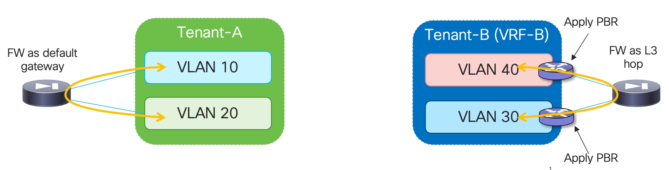
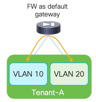
● The firewall can be deployed as default gateway for multiple network segments that are deployed as Layer 2 only networks.
● Policy based routing (PBR) can be leveraged to redirect traffic to the firewall. In this case the default gateway function is deployed on the fabric and only selective traffic flows can be directed to the firewall for security enforcement. With PBR, it is possible to ensure that each network functions as a separate security zone, but with the flexibility of specifying the subset of traffic flows to inspect (depending on the specific policy configured to redirect the traffic to the firewall instance). Also, because each network is deployed as a Layer 3 segment, it must be associated to a VRF that becomes the tenant identifier.
● A third, less common option is the one where the firewall is deployed in transparent mode, as a bump in the wire.
Figure 1 illustrates the enforcement of security policies within a tenant through the deployment of a firewall as default gateway or by leveraging the PBR functionality.
Inter-Tenant Security Enforcement
In a multi-tenant environment, each tenant is usually logically isolated from the others. In such cases, the deployment of a tenant-edge firewall allows you to apply filtering policies to data traffic moving between endpoints that belong to different tenants.
While this is also possible in the use case described in the previous section where the firewall is deployed as default gateway for the tenant’s networks, the goal is often to move the default gateway function into the fabric. In such case, the networks are deployed as Layer 3 and belong to a VRF that represents the security zone for a specific tenant.
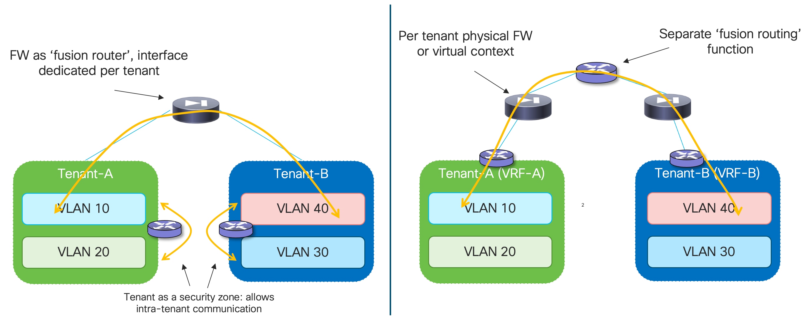
Traffic within the VRF (East-West traffic) is normally allowed, and the communication between overlay networks that are part of a given VRF is typically provided by the VXLAN EVPN routing functionality. To enable secured routing between different VRFs (tenants), a “fusion” function is usually deployed to interconnect the different firewall devices. The fusion devices can be placed at Inter-Tenant Service level or within the routing core.
Figure 2 shows the options of placing a fusion device to enable communication between tenants/VRFs and the concept of tenant/VRF level security zone.
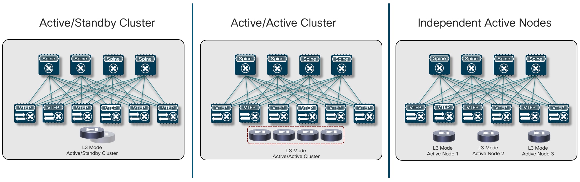
Service Nodes Redundancy Models
Different redundancy models are available to connect the service nodes to VXLAN EVPN fabrics part of a Multi-Site domain. The right choice depends on multiple factors, such as the desired level of service nodes’ resiliency, HW capabilities for the service node of choice, etc.
This section provides an overview of the three most common redundancy deployment options found in real-life deployments. After the overview, we will describe different deployment options that can leverage any of those redundancy deployment models. Specifically, the deployment of a firewall service as default gateway, the deployment of a firewall as a perimeter device (for North-South and inter-tenant/inter-VRF policy enforcement) and the use of traffic stitching to firewall service leveraging policy-based redirection functionalities.
Active/Standby Firewall Cluster Stretched across Sites
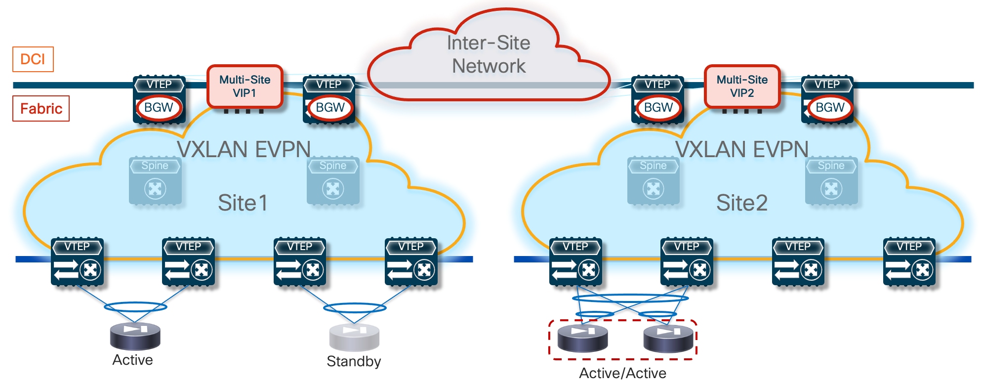
The first simple and quite common redundancy model calls for the deployment of an Active/Standby cluster of service nodes across different fabrics part of the Multi-Site domain, as shown in Figure 3 below.
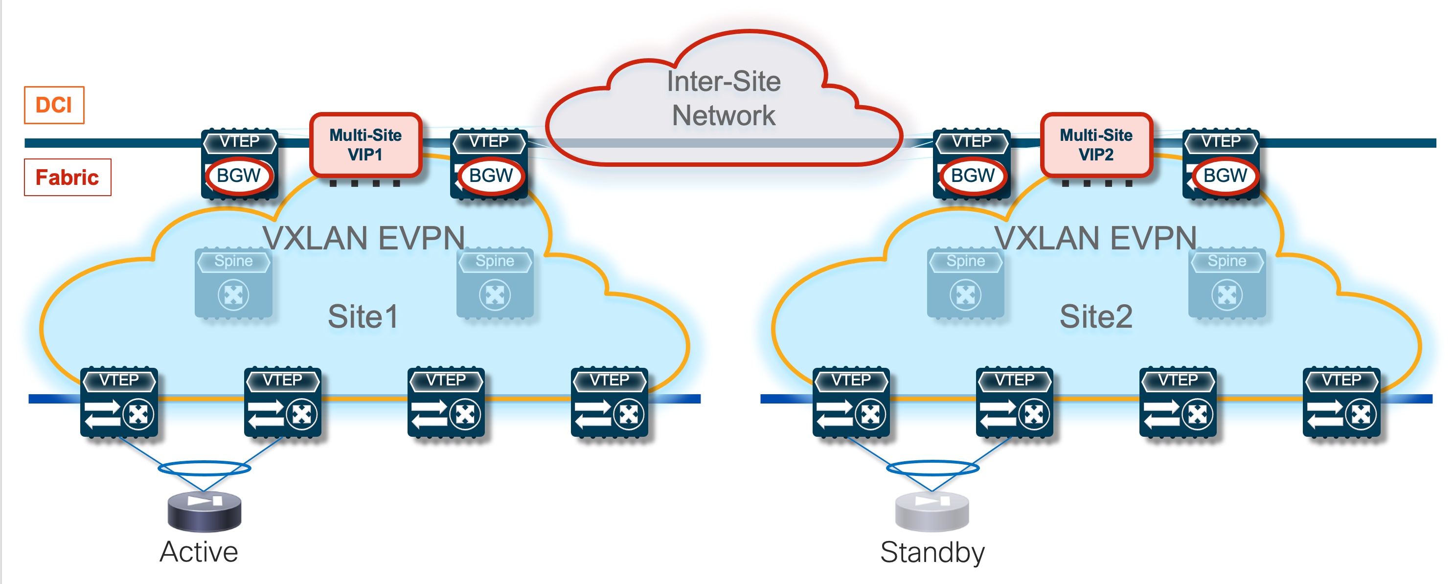
This approach makes more sense when the fabrics are co-located in the same data center or deployed in locations that are in close geographical proximity (such as metro data centers), because the obvious consequence of stretching the Active/Standby cluster across sites is the hair-pinning of traffic to the fabric where the active service node is deployed.
The connectivity extension services provided by the Border Gateway nodes allow you to abstract the physical location of the service leaf nodes and make them behave as if they were deployed next to each other. This is possible through the extension of the Layer 2 segment used to exchange keepalive, configuration information, and connection state between the active and standby nodes. Additionally, because those service nodes have their data interfaces (inside, outside, DMZ, or one-arm) assigned IP addresses that are part of common subnets (to handle failover scenarios where the units exchange their active and standby roles), those data networks must also be extended across fabrics.
Note: The failover connection can be established between the firewall nodes by extending that network via VXLAN Multi-Site as mentioned above or by leveraging a physically separate infrastructure. This second option allows you to remove any dependency on the fabric itself and providesmore robust support for the failover functionality. Finally, when the firewall nodes are co-located in the same physical locations, it may also be possible to use dedicated back-to-back connections.
There are different options on how to deploy the service nodes, which could function as default gateway for the endpoints or be connected as devices peering with the leaf nodes of the VXLAN EVPN fabrics. Also, there are different approaches on how to enforce traffic flows through the service nodes, either based on traditional bridging or routing behavior or by leveraging more advanced PBR-based functionalities. The following sections of this paper discuss all these alternative options in greater detail.
The configuration sample below highlights the configuration that must be applied on both firewall nodes to ensure that an Active/Standby cluster can be built. In the example below, a dedicated interface (Port-channel1) is used to establish that communication.
Note: The configuration below is referring to a Cisco Adaptive Security Appliance (ASA) firewall device.
Primary Firewall Node
interface Port-channel1
description LAN Failover Interface
!
failover
failover lan unit primary
failover lan interface fover Port-channel1
failover polltime unit 1 holdtime 3
failover interface ip fover 192.168.1.1 255.255.255.252 standby 192.168.1.2
Secondary Firewall Node
interface Port-channel1
description LAN Failover Interface
!
failover
failover lan unit secondary
failover lan interface fover Port-channel1
failover polltime unit 1 holdtime 3
failover interface ip fover 192.168.1.1 255.255.255.252 standby 192.168.1.2
Once the Active/Standby cluster is established, the provisioning can be done only from the active firewall node. The configuration would then be automatically synchronized to the standby unit.
It is also possible to tune the keepalive timers to speed up the detection of the failure of the active firewall and the activation of the standby unit. In this case, we recommend not to tune those timers too aggressively, to take into account the intersite traffic convergence under various link/node failure cases that may result in creating a split-brain scenario for the firewall pair. In the specific example above, keepalives are exchanged every second (polltime unit 1) and a firewall is considered failed after a 3-second timer expires (holdtime 3).
Active/Active Firewall Cluster Stretched across Sites
The evolution of the Active/Standby firewall cluster depicted in Figure 3 above is represented by the deployment of an Active/Active cluster. The immediate advantages of such approach are the better use of the deployed resources (all the firewall nodes perform concurrently their security enforcement duties) and the avoidance of the traffic hair-pinning, as each fabric can have deployed a local firewall service node (part of the stretched cluster) to handle the security enforcement for traffic flows between local endpoints (or between local endpoints and the external network domain).
Note: Some traffic hair-pinning may still occur in case of live migration of workloads across sites, depending on the specific clustering functionalities offered by the firewall model of choice. For example, with Cisco ASA and FTD firewalls, an intra-cluster traffic redirection functionality is invoked to steer the traffic back to the specific firewall cluster node that owns the connection state for a specific flow.
Before stretching an Active/Active firewall cluster across data center physical locations, it is important to verify what are the maximum Round Trip Time (RTT) latency between those sites is lower than the maximum RTT latency supported by the firewall clustering implementation. Please refer to the vendor’s firewall documentation for this information.
There are two main implementations on the market for an Active/Active firewall cluster deployment; both have applicability in the multi-fabric architecture discussed in this paper and will be discussed in the following two sections below.
Split Spanned EtherChannels Active/Active Firewall Cluster Mode
The first option consists in “bundling” all the firewall nodes together and making them look like a single logical device to the network infrastructure. For this to happen, all the firewall nodes that are part of the same cluster must share a common virtual MAC and virtual IP addresses pair for each of their data interfaces. In the specific Cisco implementation, this firewall redundancy model is called “Spanned EtherChannels Cluster Mode” because all the firewall nodes that are part of the same cluster build local port-channels that are seen as a single logical connection on the network side (Figure 4).
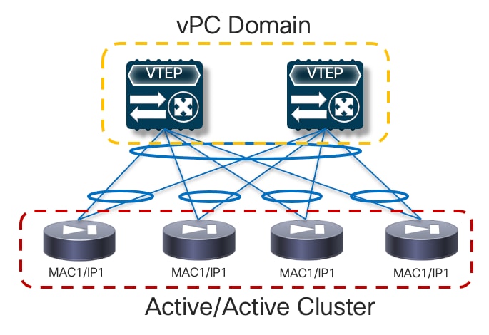
In the above example , Cisco virtual Port-Channel (vPC) technology is used to implement the single logical connection between the fabric leaf nodes and the firewall nodes that are part of the cluster. Having a single vPC on the fabric side is critical to avoid continuous MAC flapping events across different interfaces, given that all the firewall nodes use the same MAC address to send traffic into the network. The obvious consequence is that all the firewall nodes part of the same active/active cluster must be connected to the same pair of vPC leaf nodes.
A communication channel is established between all the firewall nodes that are part of the same cluster leveraging a logical Cluster Control Link (CCL). The CCL is used for control plane activities (such as exchanging keepalives, synchronizing configuration information, etc.) but can also be leveraged for data-plane communication in the scenarios where the two directions of the same traffic flow are sent to different firewall nodes. In a non-cluster scenario, those asymmetric flows would normally be dropped, whereas the use of CCL allows you to redirect and stitch the two legs of the flow via the same firewall cluster node that owns the connection state for that specific flow.
Note: Discussing the details of the Active/Active clustering implementation is out of the scope of this paper. For more information please refer to the documentation available on cisco.com:
https://www.cisco.com/c/en/us/td/docs/security/asa/special/cluster-sec-fw/secure-firewall-cluster.html
From a provisioning perspective, all the configuration is always applied on one node part of the cluster, which assumes the role of the “Master” node. All the other nodes become “Slave” nodes, capable of locally forwarding traffic but receiving configuration information from the master node via the CCL.
The configuration example below shows how to build a Cisco active/active Spanned EtherChannel firewall cluster, specifying the minimum configuration required on the master and slave nodes.
Master Node
!Name the cluster
hostname FW-Cluster
!
! enable SSH access
enable password ***** pbkdf2
crypto key generate rsa general-keys modulus 2048
username admin password testpass
aaa authentication ssh console LOCAL
ssh 0.0.0.0 0.0.0.0 management
!
! Configure the cluster interface mode
cluster interface-mode spanned
!
! Define IP pool for Mgmt
ip local pool Mgmt 10.237.99.23-10.237.99.26 mask 255.255.255.224
!
! Enable and configure the interfaces used for CCL
interface GigabitEthernet0/0
channel-group 1 mode active
no nameif
no security-level
no ip address
!
interface GigabitEthernet0/1
channel-group 1 mode active
no nameif
no security-level
no ip address
!
! Assign a virtual Mgmt IP to the cluster (each node gets also a dedicated Mgmt IP)
interface Management0/0 management-only
nameif management
security-level 100
ip address 10.237.99.22 255.255.255.224 cluster-pool Mgmt
no shutdown
!
! Create a default route for management
route management 0.0.0.0 0.0.0.0 10.237.99.1
!
! Cluster configuration
cluster group cluster1
local-unit node1
cluster-interface Port-channel1 ip 192.168.1.1 255.255.255.0
priority 1
enable
!
! Enable jumbo-frame support on the CCL link
jumbo-frame reservation
mtu cluster 1654
Slave Node
! Enable and configure the interfaces used for CCL
interface GigabitEthernet0/0
channel-group 1 mode active
no nameif
no security-level
no ip address
!
interface GigabitEthernet0/1
channel-group 1 mode active
no nameif
no security-level
no ip address
!
! Cluster configuration
cluster group cluster1
local-unit node2
cluster-interface Port-channel1 ip 192.168.1.2 255.255.255.0
priority 2
enable
Once the firewall nodes discover themselves via the CCL interfaces, they are bundled as part of the same cluster:.
FW-Cluster# show cluster info
Cluster FW-Cluster: On
Interface mode: spanned
This is "1" in state MASTER
ID : 2
Version : 9.2(2)4
Serial No.: XXXXXXXXXXX
CCL IP : 192.168.1.1
CCL MAC : 006b.f11e.fd5f
Last join : 15:05:59 UTC Nov 22 2023
Last leave: 14:46:02 UTC Nov 22 2023
Other members in the cluster:
Unit "node2" in state SLAVE
ID : 0
Version : 9.2(2)4
Serial No.: XXXXXXXXXXX
CCL IP : 192.168.1.2
CCL MAC : 006b.f11f.2a74
Last join : 16:04:23 UTC Nov 22 2023
Last leave: 16:00:56 UTC Nov 22 2023
An exception to the above guideline (connecting all the firewall nodes to the same pair of leaf nodes) is required when the active/active cluster needs to be stretched across fabrics that are part of a Multi-Site domain. This design is called “Split Spanned EtherChannels”, as the same topology shown in figure above can be used inside each fabric, essentially “splitting” the Spanned EtherChannels design (Figure 5).
The same requirement of connecting the firewall nodes to a single pair of leaf devices remains valid inside each fabric, but the firewall nodes must be connected to different leaf nodes across fabrics. Connectivity between nodes via CCL is still possible by ensuring that the CCL interfaces are mapped to a specific network (associated to an L2VNI segment) stretched across sites.
Note: As previously mentioned, CCL connectivity could also be achieved by leveraging a separate physical network infrastructure.
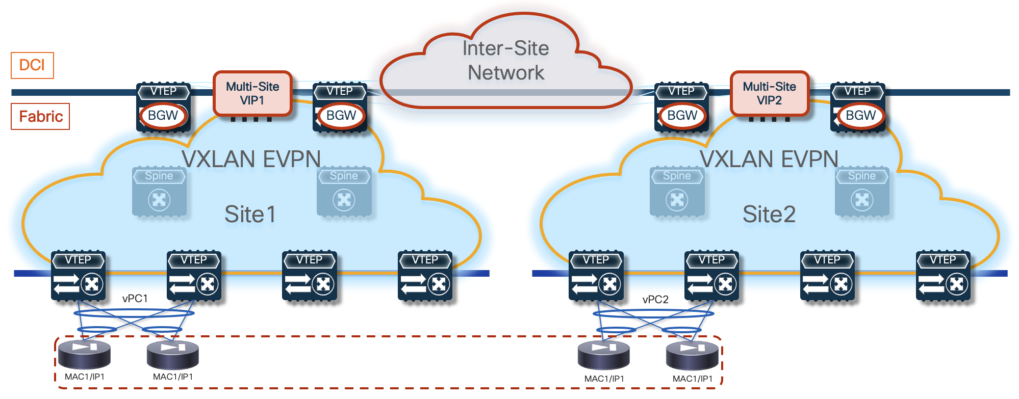
In the following sections of this document, we are going to cover different deployment models for this active/active firewall cluster. In all of those options, the data interface(s) defined on each firewall node part of the cluster share the same virtual MAC/virtual IP address (as shown in the figure above). Because of that, a specific challenge arises when stretching the cluster across different fabrics: how to handle the concurrent learning of the same vMAC/vIP information in different fabrics and how to prevent this from being seen as a continuous ‘live endpoint migration” event.
The specific solution adopted for VXLAN Multi-Site calls for the association of the logical vPC connections defined in each fabric to connect the firewall nodes (vPC1 and vPC2 in Figure 5) to a common Ethernet Segment (ES), leveraging the ESI based multi-homing functionality. This ensures that, at the Multi-Site level, learning of concurrent vMAC/vIP information on vPC1 and vPC2 is not considered a “move” event, as both connections are considered part of the same multi-homed logical segment and all the available paths are considered as “valid” to reach the firewall service.
Note: Discussing the details of EVPN multi-homing is out of the scope of this paper. For more information, please refer to the documents below: https://www.rfc-editor.org/rfc/rfc7432.html
https://www.cisco.com/c/en/us/td/docs/dcn/nx-os/nexus9000/104x/configuration/vxlan/cisco-nexus-9000-series-nx-os-vxlan-configuration-guide-release-104x/m-interoperability-with-mvpn-multi-homing-using-esi.html
It is worth noticing how the use of EVPN multi-homing described in this document is specifically focused on the deployment of an active/active firewall stretched across VXLAN EVPN fabrics. Therefore, only a subset of the EVPN multi-homing functionalities discussed in the documents above are required. The points below discuss some functional considerations and provide the configuration required to enable this subset of functionalities.
Because firewall nodes with the same vMAC/vIP addresses are connected to different sites, each VTEP device that is part of the Multi-Site domain should be able to properly handle that same vMAC/vIP information pointing to different locations (different fabrics) and determine the best path to access the firewall service. Figure 6 highlights a deployment of three VXLAN EVPN fabrics part of a Multi-Site domain, with the Active/Active firewall cluster stretched across Site 1 and 2.
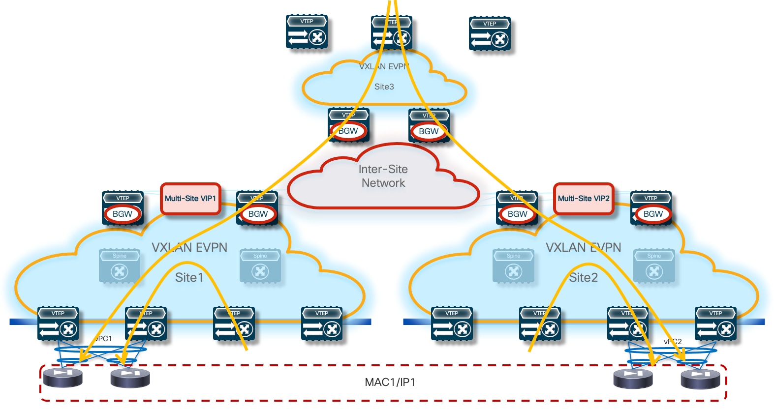
Any communication originated in Site3 and requiring access to the firewall service would have two paths available, leading to the firewall nodes in Site1 or Site2. Load-balancing of traffic flows will be handled (on a per-flow basis) by the BGW nodes deployed in Site3. Communication initiated from Site1 or SIte2 should instead always prefer the connectivity to one of the firewall nodes locally deployed in that site.
Note: On any sites that do not have a firewall service locally deployed (such as Site 3 in the example above), it is necessary to configure “bestpath AS-Path multipath-relax” as part of the BGP configuration on its BGWs so that the BGWs can treat the clustering routes received from remote sites’ BGWs as ECMPs. Without this configuration, the BGWs in Site 3 will not be able to install the remote routes as ECMPs because they will have been received from differing neighboring ASNs. It will also be necessary to configure “maximum-paths” under the L2VPN/EVPN address family so that multiple paths can be selected as ECMPs and installed in the forwarding table.
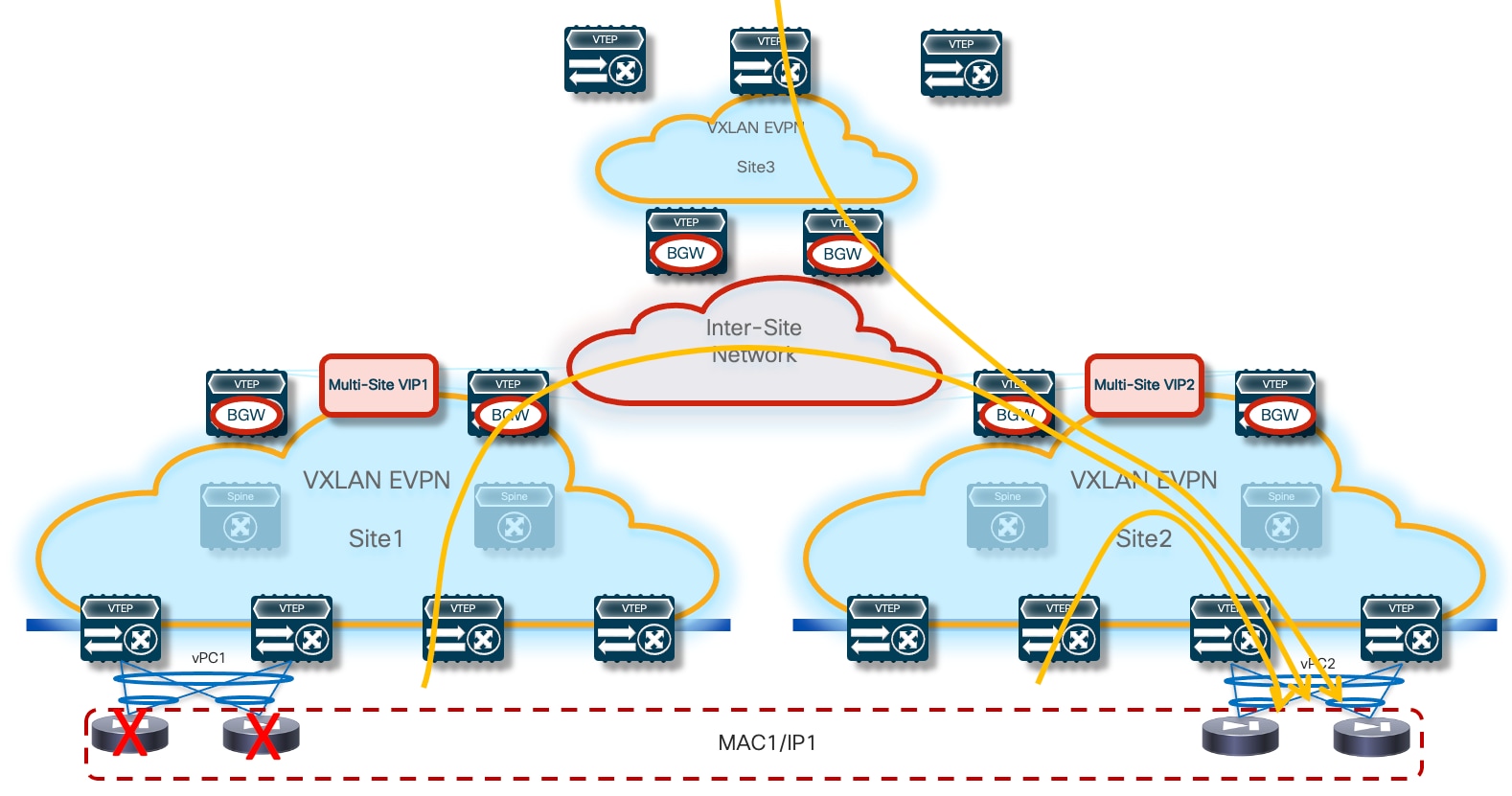
The leaf (and BGW) nodes deployed in Site1 (or Site2) also receive the vMAC/vIP information from the remote site; this ensures that in the specific scenario where all the firewall nodes deployed in a site fail (this could become more likely if a single firewall node was connected per site), traffic could be redirected to the remaining nodes still available in the other sites (Figure 7).
From an architectural perspective, the recommendation is to connect the firewall nodes to a pair of leaf nodes in each fabric and not to the Border Gateway nodes. This allows you to deploy the BGWs in Anycast mode without requiring making them part of a vPC domain (vPC BGW deployment model). If the goal is reducing the switches’ footprint, it is also possible to consolidate the spines and BGW functions on a common set of devices (instead of using a dedicated set of Anycast BGW nodes, as shown in the previous diagrams).
There are specific hardware and software considerations for the switches deployed as part of this solution, depending on the specific function they perform:
● The leaf nodes where the firewall nodes are connected and the BGW nodes must be able to propagate vMAC/vIP information to the rest of the network (across different VXLAN EVPN fabrics) leveraging EVPN multi-homing, a functionality sometimes referred to as “ESI TX”. This requires the use for all those nodes of Nexus 9000 FX2 platforms (or newer) running NX-OS 10.1(2) release (or newer).
● All the other leaf nodes must instead be able to receive and handle EVPN updates containing an ESI value different than 0, a functionality often referred to as “ESI RX”. This capability is available on all second-generation Nexus 9000 platforms (EX and newer) running as minimum the NX-OS 10.2(2)F release.
As previously mentioned, all the firewall nodes in the same site must connect to the same logical vPC connection defined on a pair of leaf nodes. The different vPCs used in different fabrics need then to be configured as part of the same ethernet-segment (ES), leveraging the simple configuration shown below.
interface port-channel 1
vpc 1
ethernet-segment vpc
esi 0012.0000.0000.1200.0102 tag 1012
The <vpc> keyword needs to be configured for the specific firewall clustering feature, as it removes the need of performing the Designated Forwarder (DF) election using EVPN Type-4 advertisement (the DF nose is responsible for the forwarding of BUM traffic for each specific L2VNI segment). This is because normal vPC DF election is implemented instead.
The firewall cluster vMAC/vIP addresses are advertised into the multi-fabric control plane as EVPN Route-Type 2 with the ESI set to the configured value on each vPC port-channel interface. Inside each fabric, the next-hop for those routes is always going to be the vPC VIP defined for the local service leaf nodes. When this information is propagated outside of the fabric by the BGW nodes, the next-hop is going to be changed to the Multi-Site VIP address identifying all the BGW nodes in that specific site. Additionally, Ethernet Auto-Discovery (EAD) / Ethernet Segment (ES) information is also injected by the service leaf nodes as EVPN Route-Type 1. Specific configuration should be applied on the service leaf nodes and on the BGW nodes to be able to identify those messages and forward them consistently across fabrics.
As shown in the previous configuration sample, the clustering ethernet-segment defined on the vPC service leaf nodes has a 4-byte tag assigned to it. This tag has only local significance and will not be propagated by BGP outside of the originating leaf VTEP, so an originate-map route-map policy needs to be configured to match the tag and attach a community to all matching EVPN Route-Type 1 and 2 advertisements so they can be identified on the BGW nodes as belonging to the firewall cluster.
! Define the route-map to attach the community to T1/T2 routes
route-map SET_FW_COMMUNITY permit 10
match tag 1012
match evpn route-type 1 2
set community 12:10012
!
! Apply the route-map to the L2VPN EVPN address-family
router bgp 65001
address-family l2vpn evpn
originate-map SET_FW_COMMUNITY
On the BGWs of each site where the cluster nodes are deployed, specific route-maps are then defined to match the community applied by the service leaf nodes and to propagate the ESI value received with the routes across the site’s boundary without modifying it. Remote sites receiving the EAD/ES and MAC/IP routes containing the ESI information can then exercise the multi-homing logic to balance traffic across multiple sites attached to the same firewall cluster. Notice how different route-maps are applied on the internal EVPN peerings established with the spines and on the external EVPN peerings established with remote BGW nodes.
! Define a community-list to match the community applied on the service leaf nodes
ip community-list standard MATCH_FW_COMMUNITY seq 5 permit 12:10012
!
! Define the route-map to be associated to EVPN peerings with spines
route-map PRESERVE_ESI_Fabric permit 10
match community MATCH_FW_COMMUNITY exact-match
match evpn route-type 2
set esi unchanged
route-map PRESERVE_ESI_Fabric permit 15
!
! Define the route-map to be associated to EVPN peerings with remote BGWs
route-map PRESERVE_ESI_DCI permit 10
match community MATCH_FW_COMMUNITY exact-match
match evpn route-type 2
set esi unchanged
route-map PRESERVE_ESI_DCI permit 15
match community MATCH_FW_COMMUNITY exact-match
match evpn route-type 1
route-map PRESERVE_ESI_DCI deny 20
match evpn route-type 1
route-map PRESERVE_ESI_DCI permit 30
!
! Apply the defined route-maps to the spine and remote BGW neighbors
router bgp 65001
neighbor 10.12.0.3
remote-as 65001
update-source loopback0
address-family l2vpn evpn
send-community
send-community extended
route-map PRESERVE_ESI_Fabric out
neighbor 10.22.0.3
remote-as 65002
update-source loopback0
ebgp-multihop 5
peer-type fabric-external
address-family l2vpn evpn
send-community
send-community extended
route-map PRESERVE_ESI_DCI out
Note: Each BGW and vPC service leaf node must also configure “send-community” under the L2VPN/EVPN address-family of their BGP peers so that the community attached to the clustering routes can be propagated along the way. If there are route-reflectors and/or route servers, they must be configured accordingly as well.
At the end of the configuration, it is possible to verify that the firewall cluster has been properly formed by using the CLI command shown below (valid for a two nodes Active/Active cluster).
FW-Cluster# show cluster info
Cluster FW-Cluster: On
Interface mode: spanned
This is "node1" in state MASTER
ID : 0
Version : 9.2(2)4
Serial No.: XXXXXXXXXXX
CCL IP : 66.66.66.1
CCL MAC : 006b.f11f.2a74
Last join : 04:49:51 UTC Nov 25 2023
Last leave: 04:45:18 UTC Nov 25 2023
Other members in the cluster:
Unit "2" in state SLAVE
ID : 2
Version : 9.2(2)4
Serial No.: XXXXXXXXXXX
CCL IP : 66.66.66.2
CCL MAC : 006b.f11e.fd5f
Last join : 05:13:10 UTC Nov 25 2023
Last leave: 05:10:06 UTC Nov 25 2023
Individual Interface Active/Active Cluster Mode
In this second option, each firewall node maintains its own identity (in terms of MAC and IP addresses) for each locally defined data interface. As displayed in Figure 8 below, this provides more flexibility on how to connect the firewall nodes to the fabric, removing the need to use the same vPC pair of devices in each fabric.
The use of the Cluster Control Link applies also with this redundancy model and allows you to achieve the same benefits previously described for the Split Spanned EtherChannel mode.
Below is the configuration that must be applied to the cluster’s control node and to the data nodes in order to ensure the cluster can be successfully formed. The initial configuration for the control node includes the bootstrap configuration followed by the interface configuration that will be replicated to the data nodes that are part of the same cluster.
Control Node
A few important considerations for the configuration required on the control node:
● The cluster interface mode must now be configured as “individual” to distinguish the Active/Active cluster deployment model from the previously described “Split Spanned EtherChannel” mode.
● IP pools must be defined to assign the IP addresses to each node that is part of the cluster. The range must ensure that one address is available for the control node and all the data nodes.
● The control node will define a unique IP address for its management and data interfaces (Mgmt and one-arm in the example below) not included in the specified ranges. Those are the IP addresses that are always reachable on the active control node and can move across nodes of the cluster when the active control node fails. Note that the use of this “virtual IP” is instead not required for the interface used as cluster control link, because its IP address is configured for each node part of the cluster as part of the specific “cluster group” configuration.
● BecauseBecause the cluster control link traffic includes data packet forwarding, the cluster control link needs to accommodate the entire size of a data packet plus cluster traffic overhead (100 bytes). It is hence recommended to increase the MTU associated to the CCL interface to accommodate this extra information. Doing so requires jumbo frame reservation (see the “jumbo-frame reservation” command).
Note: The control node must be reloaded after entering the commands required to increase MTU on the CCL link.
! Name the cluster
hostname FW-Cluster
!
! enable SSH access
enable password ***** pbkdf2
crypto key generate rsa general-keys modulus 2048
username admin password testpass
aaa authentication ssh console LOCAL
ssh 0.0.0.0 0.0.0.0 management
!
! Configure the cluster interface mode
cluster interface-mode individual
!
! Define IP pools
ip local pool CCL 192.168.1.1-192.168.1.4 mask 255.255.255.0
ip local pool one-arm 172.16.1.11-172.16.1.14 mask 255.255.255.0
ip local pool Mgmt 10.237.99.23-10.237.99.26 mask 255.255.255.224
!
! Enable and configure the interfaces
interface GigabitEthernet0/0
no shutdown
!
interface GigabitEthernet0/1
nameif one-arm
security-level 0
ip address 172.16.1.10 255.255.255.0 cluster-pool one-arm
no shutdown
!
interface Management0/0
management-only
nameif management
security-level 100
ip address 10.237.99.22 255.255.255.224 cluster-pool Mgmt
no shutdown
!
! Create a default route for management
route management 0.0.0.0 0.0.0.0 10.237.99.1
!
! Cluster configuration
cluster group cluster1
local-unit node1
cluster-interface GigabitEthernet0/0 ip 192.168.1.1 255.255.255.0
priority 1
enable
!
jumbo-frame reservation
mtu cluster 1654
Data Nodes
For each data node, the only configuration required to ensure that each data node can join the cluster with the control node (and receive additional required configuration) is the “cluster group” configuration shown below.
! Configure the cluster interface mode
cluster interface mode individual
!
! Enable CCL interface
interface GigabitEthernet0/0
no shutdown
!
! Cluster configuration
cluster group cluster1
local-unit node2
cluster-interface GigabitEthernet0/0 ip 192.168.1.2 255.255.255.0
priority 2
enable
Note: The only parameters to change on the different data nodes are the “local-unit” name, the cluster interface IP address, and the priority.
At the end of the configuration, it is possible to verify that the firewall cluster has been properly formed by using the CLI command shown below.
FW-Cluster# show cluster info
Cluster cluster1: On
Interface mode: individual
Cluster Member Limit : 16
This is "node1" in state CONTROL_NODE
ID : 0
Version : 9.19(1)
Serial No.: XXXXXXXXXXX
CCL IP : 192.168.1.1
CCL MAC : 0050.56b7.5ece
Module : ASAv
Resource : 4 cores / 8192 MB RAM
Last join : 21:27:34 UTC Oct 27 2023
Last leave: 21:26:30 UTC Oct 27 2023
Other members in the cluster:
Unit "node2" in state DATA_NODE
ID : 1
Version : 9.19(1)
Serial No.: XXXXXXXXXXX
CCL IP : 192.168.1.2
CCL MAC : 0050.56b7.7bca
Module : ASAv
Resource : 4 cores / 8192 MB RAM
Last join : 21:18:42 UTC Oct 27 2023
Last leave: N/A
Unit "node3" in state DATA_NODE
ID : 2
Version : 9.18(3)56
Serial No.: XXXXXXXXXXX
CCL IP : 192.168.1.3
CCL MAC : 0050.56b7.8c90
Module : ASAv
Resource : 4 cores / 8192 MB RAM
Last join : 21:20:05 UTC Oct 27 2023
Last leave: N/A
Unit "node4" in state DATA_NODE
ID : 3
Version : 9.18(3)56
Serial No.: XXXXXXXXXXX
CCL IP : 192.168.1.4
CCL MAC : 0050.56b7.f68f
Module : ASAv
Resource : 4 cores / 8192 MB RAM
Last join : 21:22:00 UTC Oct 27 2023
Last leave: N/A
Independent Firewall Services Deployed per Site
This redundancy model is desirable when the goal is to operate the different fabrics in a more “loosely coupled” fashion, removing the need to extend networks across sites for the clustering of service nodes connected to different fabrics. This means that the redundancy of the firewall function must be handled at the single fabric level, which can be achieved by leveraging any of the two clustering options described in the previous sections or by deploying different independent firewall nodes in a given fabric.
Important Considerations for Deploying This Redundancy Model
First, it is possible to “mix and match” the redundancy models used inside each fabric. For example, Figure 10 shows a scenario where an Active/Standby cluster is deployed in fabric 1, whereas an Active/Active cluster is used in fabric 2.
The deployment of independent active nodes inside the same fabric shown on the right of Figure 9 implies that there is no use of any clustering capability between the firewall nodes. Therefore, it becomes responsibility of the network deployment to ensure that the two legs of the same traffic flow can be stitched through the same firewall node that owns the connection state for that communication. As it will become clear in the rest of this paper, doing this via traditional routing configuration becomes quite challenging and the use of enhanced Policy-Based Redirection (ePBR) is the recommended solution to achieve this goal.
Similar considerations apply for the firewall services deployed across sites, even if a clustering redundancy model were to be used inside each fabric (as shown in Figure 10). It is mandatory to avoid creating asymmetric traffic paths via the independent firewalls services deployed in separate sites, which would result in dropping the stateful traffic flows because connection state is not synchronized between those devices. ePBR can provide the easiest answer also to this requirement. This also implies that, depending on the specific use case under consideration, live migration of endpoints across the sites could not allow to maintain the stateful session established with the firewall node(s) in the original fabric.
Finally, another consequence of the lack of clustering of services across sites is the requirement of consistently defining the configuration and the security policies on all the firewall nodes deployed across sites. One way to address this is by using a common tool managing the various firewall instances deployed in different fabrics.
Now that we’ve introduced the most common firewall redundancy models, the following sections will discuss how to use them in the following distinct deployment scenarios:
● Firewall as Default Gateway connected to the northbound network either via static routing or using a routing protocol.
● Firewall deployed as “perimeter service” to apply security policy to all the flows leaving (or entering) a specific tenant/VRF domain.
● Use of enhanced Policy-Based Redirection (ePBR) to stitch traffic flows between endpoints through a routed firewall service (both for North-South and East-West communication). In this case, the recommendation is to connect the firewall service in one-arm mode to the fabric in order to simplify the routing configuration on the firewall itself.
The deployment of the Firewall function as default gateway for the endpoints connected to the fabric is appropriate when the requirement is the creation of small security zones mapping to each specific IP subnet (on a per VRF level), as shown in the logical representation in Figure 11:
In this case, VXLAN Multi-Site only needs to provide Layer-2 connectivity between the endpoints connected to the different subnets and the default gateway function implemented on the Firewall device.
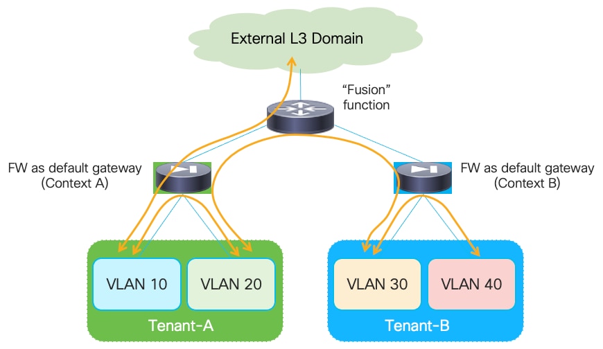
In a multi-VRF (multi-tenant) deployment, a separate firewall service (physical or logical) is usually assigned for each tenant/VRF, to separate the operational duties for the different tenants and simplify the application of inter-VRF security policies. Most of the firewall products available on the market (including Cisco ASA and FTD models) support device virtualization capabilities allowing to assign different virtual devices (usually referred to as “contexts”) to each tenant/VRF.
All traffic that needs to leave a specific VRF domain, will then be sent from the firewall toward a northbound device, based on static routing information configured on the firewall or through the dynamic exchange of reachability information via a routing protocol (IGP or BGP). The northbound device provides a “Fusion” function to connect IP subnets that are part of different tenants/VRFs and for allowing connectivity between each VRF routing domain and the external network domain, as highlighted in Figure 12:
The “Fusion” function could be deployed directly on the VXLAN EVPN fabrics (using a dedicated “Outside VRF”) or on physical external devices. Because firewalls are often physically connected to service leaf nodes in the fabric, the definition of an outside VRF is quite common (and recommended) as it allows you to leverage the Layer 3 forwarding capabilities of the fabric, rather than using it only as a Layer 2 service to interconnect the firewall with the external router.
The establishment of the communication patterns shown in figure above requires the exchange of reachability information between the firewall nodes and the devices performing the “Fusion” function. This can be achieved leveraging static routing or dynamic routing protocol, as clarified in the sections below.
When considering the firewall redundancy models discussed in the previous sections of this paper, only the use of clustering options (Active/Standby or Active/Active) are considered (and recommended) when the firewall is deployed as default gateway. This is because ensuring that the two legs of a given traffic flow are steered through the same firewall node becomes quite challenging if independent firewall services are deployed across different fabrics (and it is also usually not possible to define the same default gateway function on different firewall devices connected in separate sites).
Active/Standby Firewall Cluster as Default Gateway Stretched across Sites
The first redundancy model considered for the firewall as default gateway option is the deployment of an Active/Standby firewall cluster stretched across sites. As mentioned above, this requires establishing Layer 3 connectivity between the active firewall node and a northbound Layer 3 network device.
The following two sections focus on the use case where the northbound device is represented by a dedicated stretched VRF deployed in the VXLAN Multi-Site domain. For the connectivity with the firewall, we cover both the options of static routing and the use of a dynamic routing protocol (BGP).
Note: BGP is always the recommended routing protocol to connect Layer 3 devices (firewall, load-balancer, external routers) to the fabric because of the many advanced functionalities offered by this protocol in terms of prefix filtering, routing loops avoidance, etc.
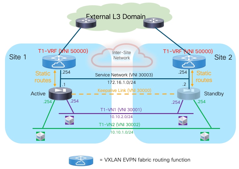
Use of Static Routing between the Firewall and the Leaf Nodes
Given that all communication between the endpoints and the rest of the network (i.e. the external network domain or a different Tenant/VRF routing domain) is always enforced via the active firewall node functioning as default gateway, the simplest approach consists in using static routing between the active firewall and the northbound network.
Note: The logical diagram shown in Figure 13 applies to a specific tenant. The same design would need to be replicated ‘n’ times for the multi-tenant scenario shown in previous Figure 12.
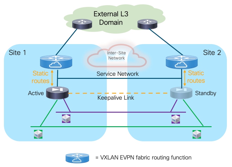
Deployment this use case requires extending several network segments across fabrics. For that purpose, it is advantageous to leverage the Layer-2 extension capabilities offered by the VXLAN Multi-Site architecture.
The specific networks that need to be extended across sites are:
● The Layer 2 segments where the endpoints are connected
This is because the default gateway for those endpoints can move across sites (based on a firewall failover event) and it is required to ensure that the endpoints always have reachability toward their active default gateway. The active and standby firewall nodes have multiple internal interfaces associated to each of those endpoints’ subnets. Those interfaces are usually logical ones, each mapped to a dedicated VLAN trunked on the physical connection (usually a local port-channel or a vPC) with the fabric nodes.
● The keepalive link used for syncing configuration and state information between the Active and Standby service nodes
Assuming the latency is not above the maximum value supported for this function by the deployed firewall (please always refer to the firewall’s specific documentation), it is a quite useful and flexible option using a Layer 2 segment extended across fabrics for this specific function (because a direct connection between the firewall nodes may not be a viable option between separate sites). The recommendation is therefore to use a separate physical interface for this function, connecting the firewall to a pair of leaf nodes (with a local port-channel or a vPC).
● The Service Network used to connect the firewall devices to the upstream Layer-3 devices
This is required to allow the Active and Standby firewalls to get assigned IP addresses on the same IP subnet and to track the health of their interfaces connected to that network. A failover event could for example be triggered if the standby node detected that the interface of the active firewall connecting it to the Service Network has failed, even if the active firewall itself hadn’t failed (this condition could be detected via the dedicated keepalive link). The outside interface of the firewalls is usually a logical one, and the connectivity with the fabric nodes is achieved on a dedicated VLAN carried on the same port-channel (or vPC) already used to trunk the VLANs associated to the internal Layer 2 segments.
Note: In the example shown in Figure 13, the northbound Layer 3 network where the service nodes are connected is represented by a specific VRF routing domain deployed in the VXLAN fabric, as it is a quite common deployment option. However, the same considerations listed above for the Service Network continue to apply even if the VXLAN EVPN fabric only performs Layer 2 duties to connect the service nodes to upstream Layer 3 devices external to the fabric.
The establishment of connectivity between endpoints part of subnets of the same Tenant (intra-Tenant East-West communication) is achieved through the active firewall performing the duties of default gateway for all those subnets. The fabric only performs Layer 2 forwarding duties to allow intra-subnet communication between endpoints and to send any routed flows to the firewall.
Traffic flows between endpoints of a specific Tenant and endpoints of a different Tenant (inter-Tenant East-West communication) or between the endpoints of a specific Tenant and the rest of the network (North-South communication) must also be steered to the active firewall performing the duties of default gateway.
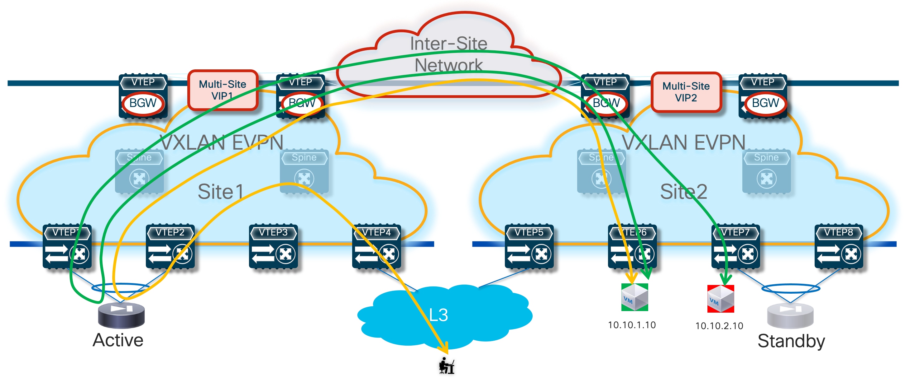
Because that default gateway function is only available in the fabric where the active firewall is connected, the immediate consequence is traffic hair-pinning when endpoints located in remote sites requires to communicate with resources outside of their local network. Figure 14 highlights this behavior both for communications between endpoints part of different subnets defined inside the data center (intra-Tenant East-West traffic) and for communication with the external network domain (North-South traffic).
Additionally, the establishment of North-South communication requires the configuration of static routes both on the firewall node and on the service leaf nodes.
A default route (0.0.0.0/0) can be configured on the firewall using as next-hop address the anycast gateway IP address defined on the fabric for the Service Network VXLAN segment. A consistent anycast gateway IP address is deployed across fabrics on all the leaf nodes where the active and standby firewall nodes are connected, so that the same next-hop address is always available wherever the firewall gets activated. BecauseBecause the anycast gateway IP address plus the interfaces of the active and standby firewalls need to be connected to a common Service Network, it is usually necessary to reserve at least a /29 subnet for that purpose (as a separate IP address is normally assigned to the interfaces of the active and standby firewalls connected to that segment).
Static entries must be also configured on the service leaf nodes connected to the firewall devices to ensure that traffic, which is originated from other tenants or from the external network and destined to the subnets of a given tenant connected behind the firewall, can be routed toward the active firewall node. The complexity of the required static routing configuration is mostly dependent on the capability of summarizing the endpoints’ address space associated to a given tenant/VRF.
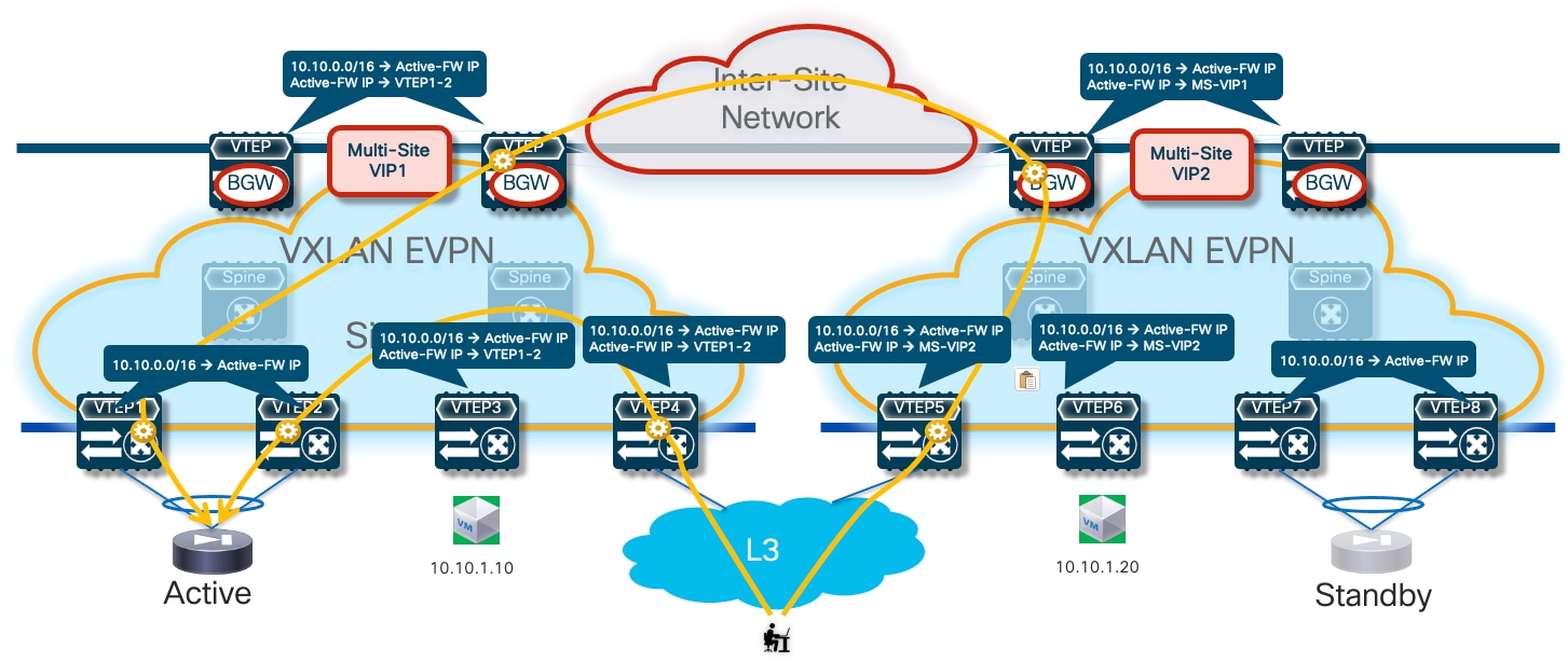
Then the default behavior of the service leaf nodes is to advertise the configured static routing information inside the local fabric’s MP-BGP EVPN control plane. As a result, all the switches (compute, border, or BGW nodes) deployed in the fabrics where the active or standby firewall nodes are located will always prefer the path via the local service leaf nodes to reach the endpoints’ subnets behind the firewall. This is the case, independently from the fact that the local firewall node is functioning in Active or Standby mode (Figure 15).
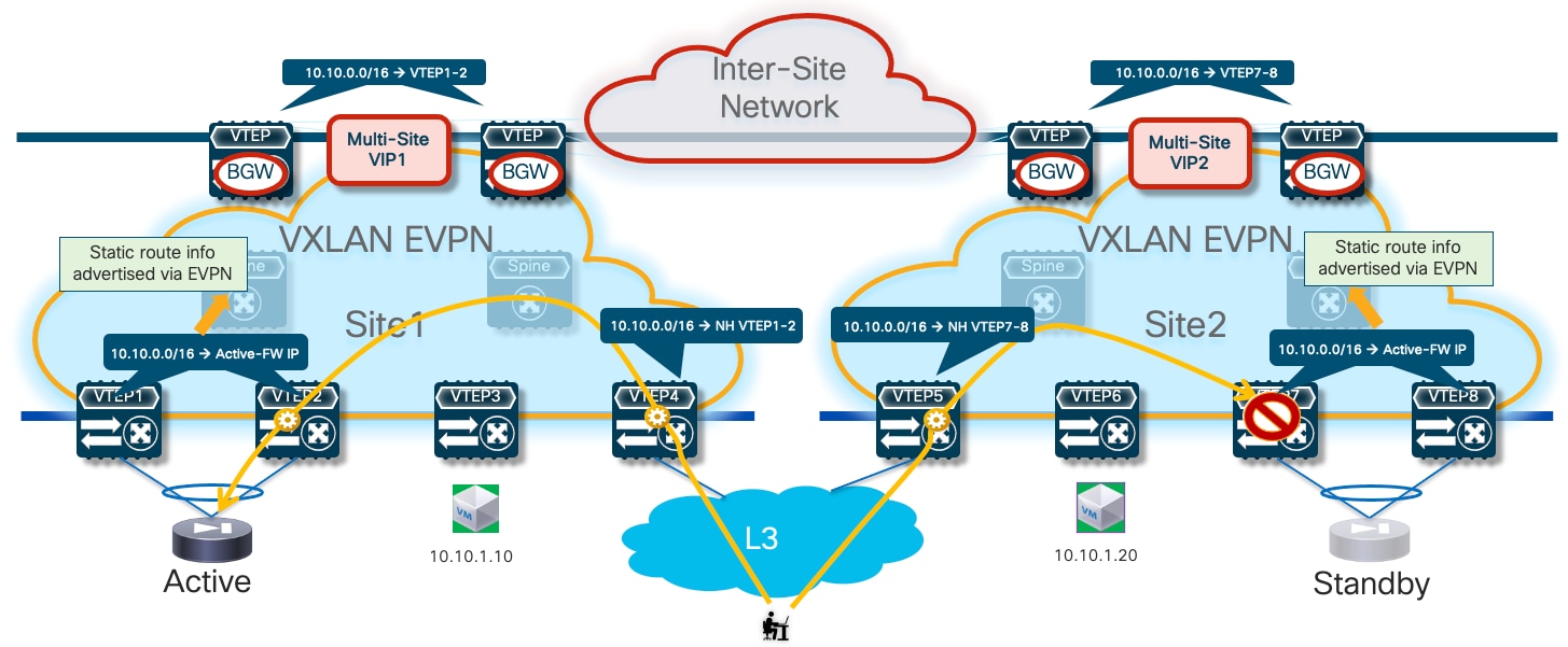
In the example shown above, routed traffic originated from an external client and destined to the green DC endpoints part of the stretched 10.10.10.0/24 IP subnet behind the firewall, could be sent toward Site1 or Site2 based on the routing information injected in the external Layer 3 network.
If the inbound traffic is received by the border leaf (BL) node in Site1, the BL would then encapsulate the flow toward the local service leaf nodes connected to the active firewall, and communication would be successfully established. In the case where inbound traffic is instead steered toward Site2, the BL node there would steer the traffic toward the local service leaf nodes connected to the standby firewall node. This behavior is not only undesirable because of the suboptimal traffic path, but it is also leading to traffic flows being dropped (the service leaf nodes in Site2 is not capable of decapsulating the traffic, performing the Layer 3 lookup and re-encapsulating it toward the service leaf nodes connected to the active firewall in Site1).
There are a few options to avoid this problem, each one is listed in order of preference and discussed in greater detail below.
Optimizing Connectivity to the Active Firewall with “export-gateway-ip”
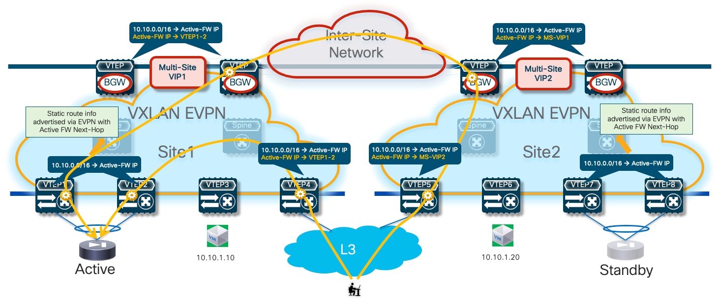
The first, and recommended option, is the enablement of the “export-gateway-ip” functionality (available since NX-OS release 9.2(1)). This allows all the leaf nodes where the VRF is instantiated (border leaf nodes in the example above, but the same applies to compute and BGW nodes) to receive via EVPN the advertisement for the static IP prefix covering all the endpoints’ subnets behind the firewall and configured on the service leaf nodes (10.10.0.0/16 in our specific example) carrying not only the next-hop of the service leaf nodes deployed in the local fabric but also the additional information of the IP address of the active firewall representing the next-hop for the static routes defined on the service leaf nodes.
A recursive routing lookup is then performed to determine how to reach that active firewall’s IP address; only the service leaf nodes connected to the active firewall have discovered that IP address as locally connected and advertised it via EVPN inside the fabric. Therefore, all the VXLAN traffic flows are now directed to those VTEPs, independently from the specific fabric where they are located (Figure 16).
If the active firewall fails, a failover event is triggered, and the standby unit becomes the new active firewall. This causes an EVPN advertisement to be propagated inside the fabric and across the fabrics steering all the traffic flows destined to the endpoints behind the firewall (Figure 17) toward those VTEPs instead.
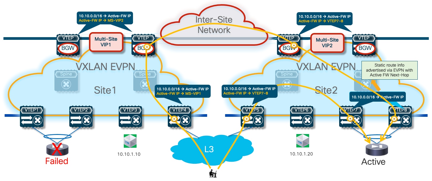
The convergence time for restoring the traffic flows is quite short and mostly dependent on the time required by the standby unit to detect the failure of the active one and promote itself as new active. As a result of this event, the newly activated firewall originates a GARP frame on the Service Network, allowing the directly connected VTEPs to discover the MAC/IP of the newly activated firewall and advertise that information inside the fabric.
The configuration required to enable the “export-gateway-ip” configuration is shown below:
! Configure the static route under the VRF
vrf context t1-vrf
ip route 10.10.0.0/16 172.16.1.1 tag 12345
!
! Define the route-map to redistribute the static route into BGP
route-map redist-static-routes
match tag 12345
set ip next-hop redist-unchanged
!
! Configure export-gateway-ip and redistribution under BGP
router bgp 65001
vrf t1-vrf1
address-family ipv4 unicast
redistribute static route-map redist-static-routes
export-gateway-ip
It is important to observe how the “export-gateway-ip” configuration shown above (without the static route definition and redistribution in BGP) should be applied also on the BGW nodes of the fabrics where the active and standby firewalls resides. This is to ensure that those BGWs advertise the active firewall IP address information in the EVPN updates sent toward the BGWs of other sites, so that those devices can also perform a recursive routing lookup for the active firewall’s address and send the traffic to the BGWs of the site where that active firewall is located (Figure 18).
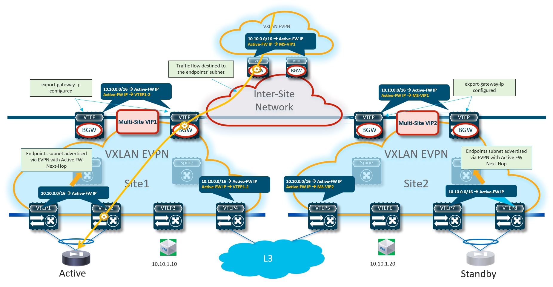
Figure 19 shows what would happen if the “export-gateway-ip” was not configured on the BGWs nodes of the fabrics where the active and standby firewalls are connected.
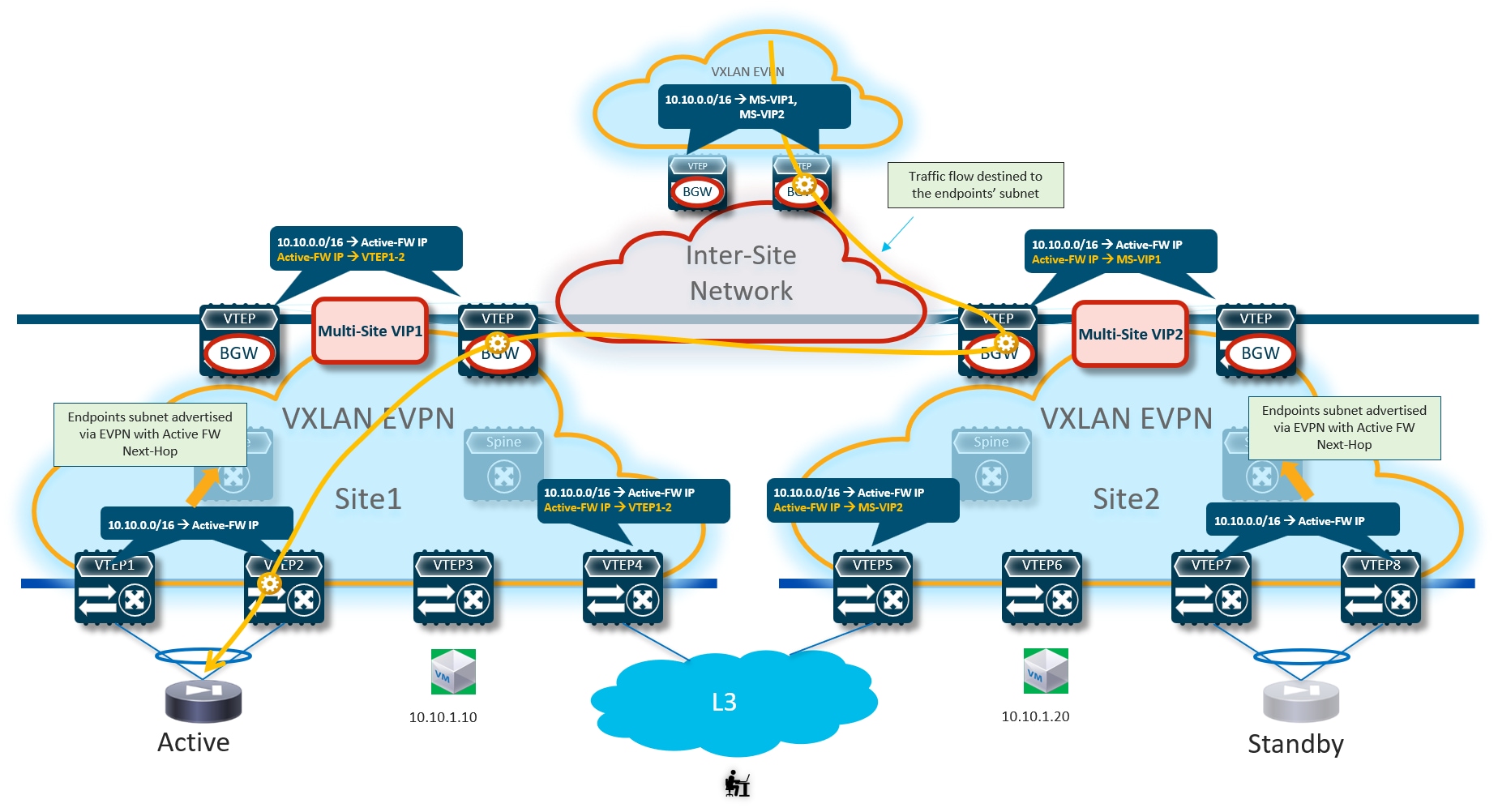
In this case, the BGWs in a third site learn the static route prefix with associated next-hops the Multi-Site VIP addresses of both fabrics where the active and standby firewalls are connected. Therefore, half of the traffic flows are steered toward the site with the standby firewall (Site2 in the example above). The BGWs in that site can decapsulate the traffic, perform a Layer 3 lookup and re-encapsulate toward the BGWs of the site with the active firewall. Even if the traffic is not dropped, this represents a suboptimal behavior that can simply be avoided configuring “export-gateway-ip” on the BGW nodes.
Optimizing Connectivity to the Active Firewall with Distributed Recursive Static Routes
A second option to steer traffic flows only to the service leaf nodes connected to the active firewall consists in leveraging again recursive routing (similarly to the “export-gateway-ip” approach just discussed) by configuring the same static route not only on the service leaf nodes connected to the firewalls, but also on all the leaf nodes (compute leaf, border leaf and BGW nodes) where the VRF is being instantiated.
Given that the static route configuration is distributed on all the leaf nodes, in this scenario there is no need for the service leaf nodes to redistribute such information in the fabric’s EVPN control plane. Only the border or border gateway nodes must advertise such information toward the external network or toward remote BGW nodes.
Because the next-hop for the static route is represented by the IP address of the active firewall, a recursive lookup is going to be triggered on all the VTEPs that are not directly connected to the active firewall to determine how to reach that specific IP address. The use of the recursion always ensures that traffic is steered toward the service leaf nodes that discovered the active firewall node as directly connected and injected such information inside the fabric (Figure 20).
Like in the scenario leveraging “export-gateway-ip” shown in Figure 17, the traffic convergence after a firewall failover event is mainly dependent on the activation of the standby firewall node and the discovery of its MAC/IP address on the directly connected service leaf nodes.
The main drawback of this solution is that you must configure the static routes on all the VTEPs where the VRF is instantiated. Such concern can obviously be alleviated by deploying a tool, such as Nexus Dashboard Fabric Controller, to automate the provisioning of configuration on multiple fabric nodes. For more information on this approach, please refer to the configuration guide below:
https://www.cisco.com/c/en/us/td/docs/dcn/nx-os/nexus9000/104x/configuration/vxlan/cisco-nexus-9000-series-nx-os-vxlan-configuration-guide-release-104x/m_configuring_layer_4-layer_7_network_services_integration.html?bookSearch=true#Cisco_Concept.dita_aa6ab7d6-ccf5-47b2-90d0-a7c91a94a971
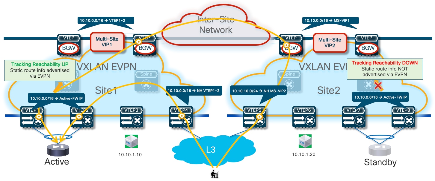
Optimizing Connectivity to the Active Firewall with Centralized Static Routing and HMM Tracking
With this last option, the static routing configuration is only provisioned on the service leaf nodes connected to the firewall devices (as it was the case with the “export-gateway-ip” scenario). A tracking mechanism (named “HMM tracking”) is introduced on the service leaf nodes to verify if the active firewall is directly connected. The HMM tracking basically checks if the firewall active IP address is locally learned on the service leaf nodes (based on the presence of the /32 prefix in the routing table). The CLI output below shows the HMM entry on the service leaf nodes relative to the firewall’s IP address.
Leaf11# show ip route vrf t1-vrf1
IP Route Table for VRF "t1-vrf1"
'*' denotes best ucast next-hop
'**' denotes best mcast next-hop
'[x/y]' denotes [preference/metric]
'%<string>' in via output denotes VRF <string>
<snip>
172.16.1.1/32, ubest/mbest: 1/0, attached
*via 172.16.1.1, Vlan400, [190/0], 1d02h, hmm
The result of the check is associated to the static route applied for the VRF, with the result that only the service leaf nodes where the active FW is connected are allowed to inject the static route information into the EVPN fabric control plane. The consequence is that, as it was the case in the scenarios previously described, all the traffic flows destined to the endpoints behind the firewall are steered toward the service leaf nodes with the connected active firewall (Figure 21).
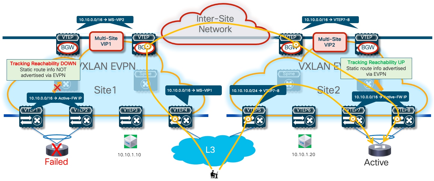
While this approach reduces the configuration touch points when compared to the use of distributed recursive routing (making it like the “export-gateway-ip” scenario), the traffic convergence mechanism after a firewall failover event results more complex:
● First, the HMM tracking mechanism needs to detect that the active firewall has moved to a new location (for example, behind VTEP7-8 in the figure above) and unlock the advertisement of static route info into the fabric’s EVPN control plane.
● At the same time, HMM tracking on the service leaf nodes where the failed active was connected needs to detect that the active firewall is gone and therefore stop advertising static route information into the fabric.
● Finally, there will also be scalability implications on the service leaf nodes when provisioning multiple static route entries with different next-hops.
The sample below show the configuration required on the service leaf nodes to enable HMM tracking and use its result to control the advertisement of static route information into the EVPN control plane.
track 1 ip route 172.16.1.1/32 reachability hmm
vrf member t1-vrf1
!
vrf context t1-vrf1
ip route 10.10.1.0/24 172.16.1.1 track 1
For more information on the use of the NX-OS object tracking functionality, please refer to the document below:
https://www.cisco.com/c/en/us/td/docs/dcn/nx-os/nexus9000/103x/unicast-routing-configuration/cisco-nexus-9000-series-nx-os-unicast-routing-configuration-guide-release-103x/m_configuring_object_tracking.html
Configuration Samples
The samples below show the configuration required on the various nodes, based on the reference topology shown in Figure 23:
Compute Leaf Nodes
Define the L2VNI segments (Layer 2 only) representing the subnets where the endpoints are connected.
vlan 2301
vn-segment 30001
!
vlan 2302
vn-segment 30002
!
interface nve1
member vni 30001
mcast-group 239.1.1.1
member vni 30002
mcast-group 239.1.1.1
!
evpn
vni 30001 l2
rd auto
route-target import auto
route-target export auto
vni 30002 l2
rd auto
route-target import auto
route-target export auto
!
interface port-channel1
description vPC to the ESXi host
switchport mode trunk
switchport trunk allowed vlan 2301-2302
spanning-tree port type edge trunk
spanning-tree bpduguard enable
mtu 9216
vpc 1
Service Leaf Nodes
On the leaf nodes where the active and standby service nodes are connected, define a VRF dedicated to each tenant and all the associated configurations to implement the northbound Layer 3 network. Notice the definition of the static route under the VRF and how to redistribute it into the EVPN control plane. In this simple example, the subnets for the endpoints are all summarized with a /16 super-net (10.10.0.0/16), whereas 172.16.1.1 represents the IP address of the active firewall node interface connected to the northbound Service Network. The same configuration must be applied to the service leaf nodes in the remote fabric where the standby firewall node is connected, with the only difference being the fabric’s specific BGP ASN value.
Note: The redistribution of the static route information into the fabric BGP EVPN control plane is required as the configuration example below leverages the use of “export-gateway-ip” command to optimize the communication with the active firewall node.
vlan 2000
vn-segment 50000
!
vrf context t1-vrf
vni 50000
ip route 10.10.0.0/16 172.16.1.1 tag 12345
rd auto
address-family ipv4 unicast
route-target both auto
route-target both auto evpn
address-family ipv6 unicast
route-target both auto
route-target both auto evpn
!
interface Vlan2000
no shutdown
mtu 9216
vrf member t1-vrf
no ip redirects
ip forward
ipv6 address use-link-local-only
no ipv6 redirects
!
route-map redist-static-routes
match tag 12345
set ip next-hop redist-unchanged
!
router bgp 65001
vrf t1-vrf1
address-family ipv4 unicast
advertise l2vpn evpn
redistribute static route-map redist-static-routes
maximum-paths ibgp 2
export-gateway-ip
address-family ipv6 unicast
advertise l2vpn evpn
redistribute static route-map redist-static-routes
maximum-paths ibgp 2
export-gateway-ip
!
interface nve1
member vni 50000 associate-vrf
Define the L2VNI segment used as firewall Keepalive Link (vn-segment 30000). The corresponding VLAN must then be trunked on the vPC connection toward the Firewall node.
Note: In this example, the endpoints L2VNIs (and associated SVIs) are not defined on the service leaf nodes, but that could obviously be the case if the logical roles of compute nodes and service leaf nodes are co-located on the same set of physical devices.
vlan 2300
vn-segment 30000
!
interface nve1
member vni 30000
mcast-group 239.1.1.1
!
evpn
vni 30000 l2
rd auto
route-target import auto
route-target export auto
!
interface port-channel1
description vPC to the Firewall Node
switchport mode trunk
switchport trunk allowed vlan 2300
spanning-tree port type edge trunk
spanning-tree bpduguard enable
mtu 9216
vpc 1
Define the Service Network used to connect the firewall nodes to the service leaf nodes. For this L2VNI it is also required to define an anycast gateway address, which represents the next-hop of the static default route defined on the firewall (see config sample later below).
vlan 3000
vn-segment 30003
!
interface Vlan3000
description Service Network
no shutdown
vrf member t1-vrf
ip address 172.16.1.254/24 tag 12345
fabric forwarding mode anycast-gateway
!
interface nve1
member vni 30003
mcast-group 239.1.1.1
!
evpn
vni 30003 l2
rd auto
route-target import auto
route-target export auto
!
interface port-channel1
description vPC to the Firewall Node
switchport mode trunk
switchport trunk allowed vlan 2300,3000
BGW Nodes
Define the VRF for each tenant and all the associated configurations to extend the VRFs between fabrics. This is required to be able to extend the Service Network, part of the VRF, across sites. Note that the full BGW configuration is not shown below, so we recomment referencing the VXLAN Multi-Site documentation for more information.
vlan 2000
vn-segment 50000
!
vrf context t1-vrf
vni 50000
rd auto
address-family ipv4 unicast
route-target both auto
route-target both auto evpn
address-family ipv6 unicast
route-target both auto
route-target both auto evpn
!
route-map fabric-rmap-redist-subnet permit 10
match tag 12345
!
router bgp 65001
vrf t1-vrf
address-family ipv4 unicast
advertise l2vpn evpn
redistribute direct route-map fabric-rmap-redist-subnet
maximum-paths ibgp 2
export-gateway-ip
address-family ipv6 unicast
advertise l2vpn evpn
redistribute direct route-map fabric-rmap-redist-subnet
maximum-paths ibgp 2
export-gateway-ip
!
interface nve1
member vni 50000 associate-vrf
!
evpn
vni 30000 l2
rd auto
route-target import auto
route-target export auto
Locally define the L2VNI segments used as firewall Keepalive Link to connect the endpoints and as Service Network to extend those networks across the fabrics.
vlan 2300
vn-segment 30000
!
vlan 2301
vn-segment 30001
!
vlan 2302
vn-segment 30002
!
vlan 3000
vn-segment 30003
!
interface nve1
host-reachability protocol bgp
source-interface loopback1
multisite border-gateway interface loopback100
member vni 30000
multisite ingress-replication
mcast-group 239.1.1.1
member vni 30001
multisite ingress-replication
mcast-group 239.1.1.1
member vni 30002
multisite ingress-replication
mcast-group 239.1.1.1
member vni 30003
multisite ingress-replication
mcast-group 239.1.1.1
!
evpn
vni 30000 l2
rd auto
route-target import auto
route-target export auto
vni 30001 l2
rd auto
route-target import auto
route-target export auto
vni 30002 l2
rd auto
route-target import auto
route-target export auto
vni 30003 l2
rd auto
route-target import auto
route-target export auto
Firewall Nodes
The configuration sample below is taken from a Cisco ASA model but can be easily adapted to apply to different types of firewall devices (physical or virtual form factors). We also assume that the required failover configuration has already been applied to build an Active/Standby firewall pair, as described in the previous “Active/Standby Firewall Cluster Stretched across Sites” section.
Configure the required inside and outside interfaces. A local port-channel interfaces (Port-channel2) is deployed on each firewall (assuming it is a physical appliance) to carry data interfaces. Sub-interfaces are created on this port-channel interface to forward traffic toward the endpoints’ subnets and toward the northbound Layer 3 device. A default static route pointing to the anycast gateway IP address defined on the service leaf nodes for the Service Network segment is used to forward all northbound traffic destined to any destination external to the specific tenant/VRF domain.
interface Port-channel2.2301
vlan 2301
nameif inside-VLAN2301
security-level 100
ip address 10.10.1.254 255.255.255.0 standby 10.10.1.253
!
interface Port-channel2.2302
vlan 2302
nameif inside-VLAN2302
security-level 100
ip address 10.10.2.254 255.255.255.0 standby 10.10.2.253
!
interface Port-channel2.3000
vlan 3000
nameif outside
security-level 0
ip address 172.16.1.1 255.255.255.0 standby 172.16.1.2
!
access-list permit-any extended permit ip any any
access-group permit-any in interface outside
!
route outside 0.0.0.0 0.0.0.0 172.16.1.254 1
Dynamic Peering between the Active Firewall and the Service Leaf Nodes
This deployment model represents a variation from the one just discussed in that the firewall node now establishes dynamic routing peering with the fabric leaf nodes. The most common and recommended option consists in using EBGP for establishing the peering, but the use of an IGP is also possible.
EBGP Peering between the Firewall and the Leaf Nodes
The logical diagram in Figure 24 shows the establishment of EBGP connectivity between the firewall and the fabric leaf nodes.
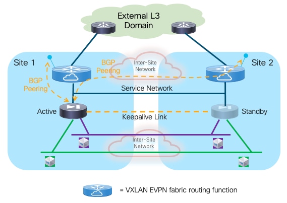
The active firewall node should establish multi-hop EBGP sessions with both the local and remote service leaf nodes (or better with unique loopback interfaces defined on those leaf nodes). This is important to minimize the traffic outage during a firewall switchover event. To understand why, let’s consider the sequence of events involved in a firewall failover event:
1. The initial conditions are the ones shown in Figure 24, where the active firewall in Site 1 has established EBGP adjacencies with the local and remote service leaf nodes.
2. Now, a firewall failover event causes the standby firewall in Site 2 to become active. The standby firewall must be configured with BGP Graceful Restart, a feature that enables BGP sessions to be restarted without causing a disruption in the network. It works by allowing the devices to maintain their established routes even after a routing peering session reset or restart, and because the routing table of the newly activated firewall is fully synchronized with the previously active firewall node, it can continue to forward traffic toward the fabric based on previously programmed information (Figure 25).
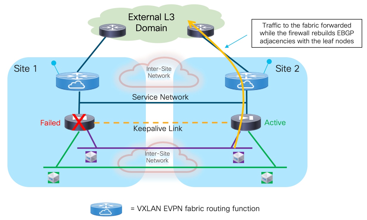
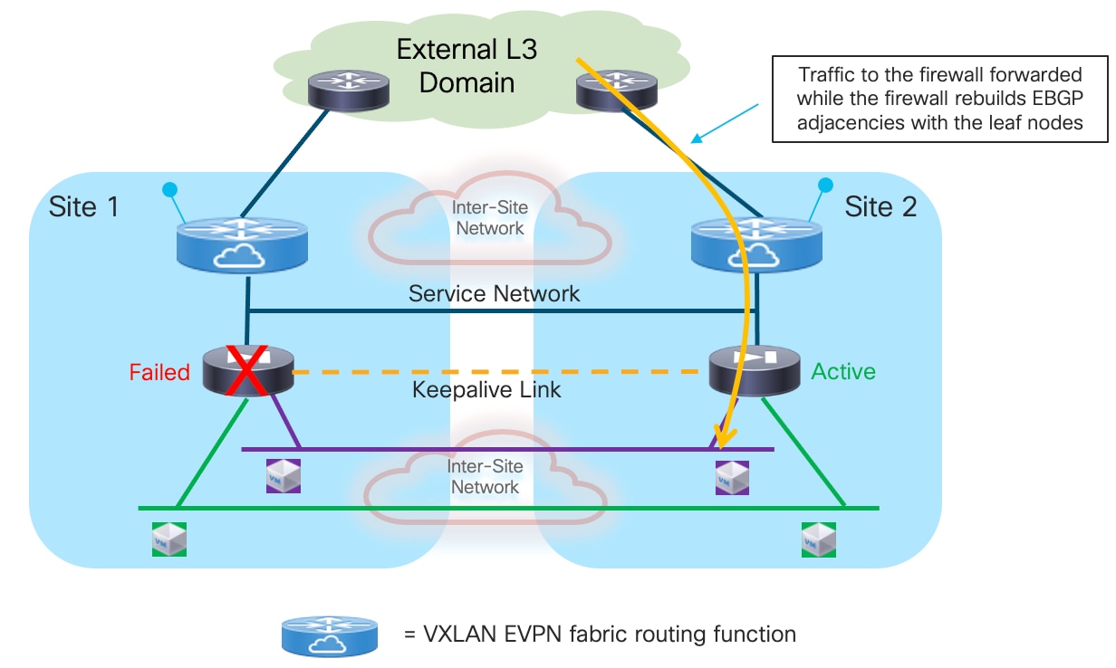
3. At the same time, the service leaf nodes are aware that the firewall is going through a BGP graceful restart event, so they do not bring down their BGP sessions established with the firewall node and as a consequence can continue to forward traffic toward the firewall based on the routing information they have received from the previously active firewall node (Figure 26). This works as the newly activated firewall inherits the same MAC/IP address of the previously active firewall. Even if the MAC changed (depending on the specific Active/Standby cluster implementation), the new associated MAC address could be learned by the service leaf nodes based on the GARP frame received from the newly activated firewall.
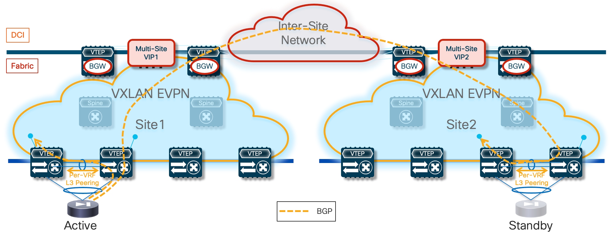
While the active firewall could establish EBGP sessions with the SVI interfaces of the local service leaf nodes connected to the Service Network segment, the same it is not possible with the remote service leaf nodes (this limitation applies to both single fabric and Multi-Site VXLAN EVPN deployments). That is why the recommended design shown in Figure 24 (logical view) and Figure 27 (physical view) calls for the use of loopback interfaces defined on the local and remote service leaf nodes to establish EBGP adjacencies with the active firewall.
Note: The same limitation mentioned above applies also to the use of Interior Gateway Protocols (IGPs – OSPF and IS-IS being the most common examples) between the firewall and the service nodes. However, with IGP protocols it is not even possible to establish adjacencies with loopback interfaces defined on the remote service leaf nodes, which is one of the reasons why we recommend using EBGP for this use case.
The Service Network is deployed on a VLAN mapped to a specific VXLAN segment (L2VNI). The L2VNI is associated to the specific VRF dedicated to the tenant and provides the anycast default gateway functionality. Static routes defined on the firewall (pointing to the L2VNI anycast gateway address) are required to reach the loopback interfaces of the local and remote service leaf nodes.
When the firewall is connected to the leaf nodes using the traditional vPC configuration (i.e. leveraging a physical vPC peer-link), it is mandatory to ensure that reachability to the loopbacks of all the service leaf nodes is always possible independently from what the physical path used to establish the EBGP sessions. There are two options to ensure this is always the case:
● Establishing a per-VRF Layer 3 peering on a dedicated VLAN carried on the vPC peer-link (Figure 27).
As shown above, this is needed on the local leaf nodes where the active firewall is directly connected because the BGP packets destined to the loopback IP address defined on leaf node 1 may be sent toward leaf node 2. Leaf node 2 by default does not learn the /32 prefix of the loopback interface of leaf node 1, as this prefix is advertised by leaf node 1 as a type-5 EVPN prefix with the vPC TEP as next-hop. Because that vPC TEP is locally defined also on leaf node 2, the received advertisement is discarded.
Note: the vPC TEP is configured as a common secondary IP address on the loopback interfaces used for the Primary IP address (PIP) on both leaf nodes part of the same vPC domain.
For the same reason, traffic destined to the loopback address of a remote leaf node is encapsulated by the remote BGWs toward the vPC TEP of that remote pair and may land on the wrong leaf node. The Layer 3 peering on the peer-link would then be needed to deliver the traffic to the loopback defined on the second service leaf node.
● Both issues described above could be avoided by enabling the “advertise-pip” knob on both the local and remote fabric either for a traditional vPC deployment (leveraging a physical peer-link connection) or for the vPC fabric peering configuration (this is the best practice recommendation). In both cases, the type-5 advertisements for the loopback /32 prefixes would use the unique PIP address defined on each leaf node as next-hop allowing always for the successful direct establishment of the EBGP peerings (Figure 28). When adopting such configuration, it is always important to keep into considerations the scalability impact in terms of maximum number of leaf nodes that could be supported in each fabric
Please refer to the latest Nexus 9000 VXLAN EVPN scalability guides for more information:
https://www.cisco.com/c/en/us/td/docs/dcn/nx-os/nexus9000/103x/configuration/scalability/cisco-nexus-9000-series-nx-os-verified-scalability-guide-1032.html
Note: with the advertise-pip and associated advertise virtual-rmac commands enabled, type-5 routes are advertised with the PIP address as next-hop and type-2 routes are still advertised with the vPC VIP address as next-hop. In addition, VMAC will be used with VIP and system MAC will be used with PIP. Those two commands must be enabled and disabled together for the feature to work properly; enabling/disabling one and not the other is considered an unsupported configuration.
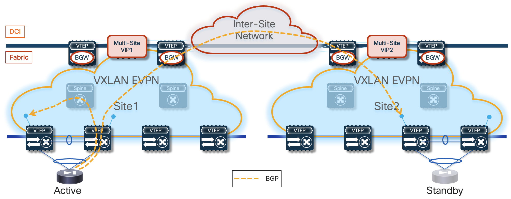
Note: As shown above for Site1, the EBGP adjacency with the locally connected service leaf 1 would happen in this case via VXLAN (through the spine), which is the reason why the same approach would work with fabric peering vPC deployments not leveraging a physical peer-link.
The establishment of EBGP adjacencies between the active firewall and both the local and remote service leaf nodes implies that the remote service leaf nodes will also receive the advertisement of the prefixes for the IP subnets for which the firewall performs the function of default gateway (for example, the prefix 10.10.1.0/24 as shown in Figure 29 below).
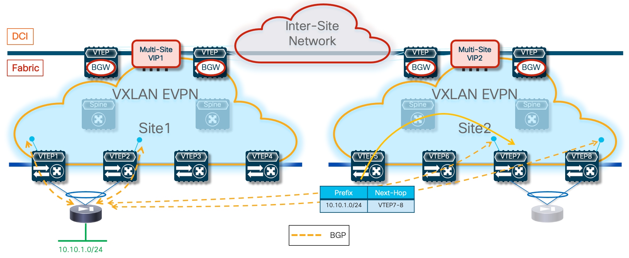
Those prefixes will then be injected by the service leaf nodes into the MP-BGP EVPN control plane of the remote fabric and advertised to all the other leaf nodes deployed in that fabric. Therefore, the leaf nodes in the remote fabric will always prefer by default the path to those prefixes advertised by the local service leaf nodes that are connected to the standby firewall. The service leaf nodes are not capable of decapsulating the VXLAN traffic, performing a Layer 3 forwarding lookup, and re-encapsulating the traffic toward the leaf nodes connected to the active firewall, so they will simply drop the traffic (Figure 30).
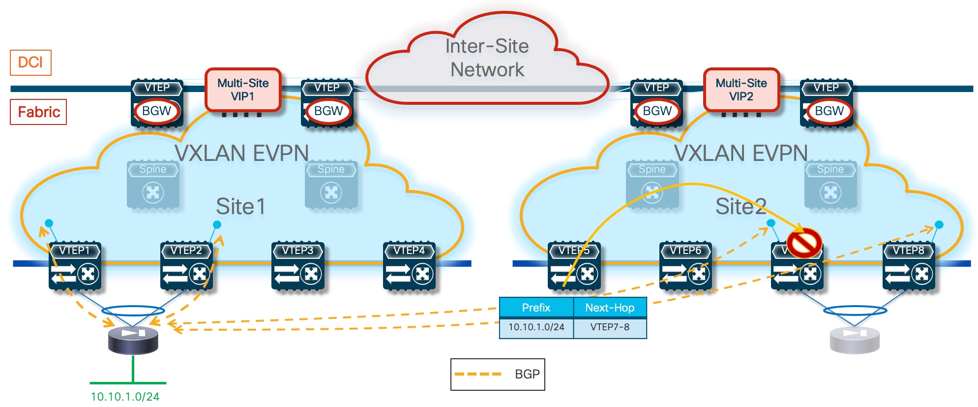
This is similar to what we already discussed for the use of static routing with an Active/Standby cluster (see previous Figure 15), so the different solutions discussed for that use cases are possible here as well. The best practice recommendation is to leverage the “export-gateway IP” functionality, which allows the leaf nodes in Site2 to install the IP address of the active firewall in their forwarding tables as next-hop to reach the endpoints’ subnet prefixes. Performing a recursive lookup toward the active firewall IP ensures that traffic can be steered directly toward the service leaf nodes connected to it, following the sequence of steps shown in Figure 31.
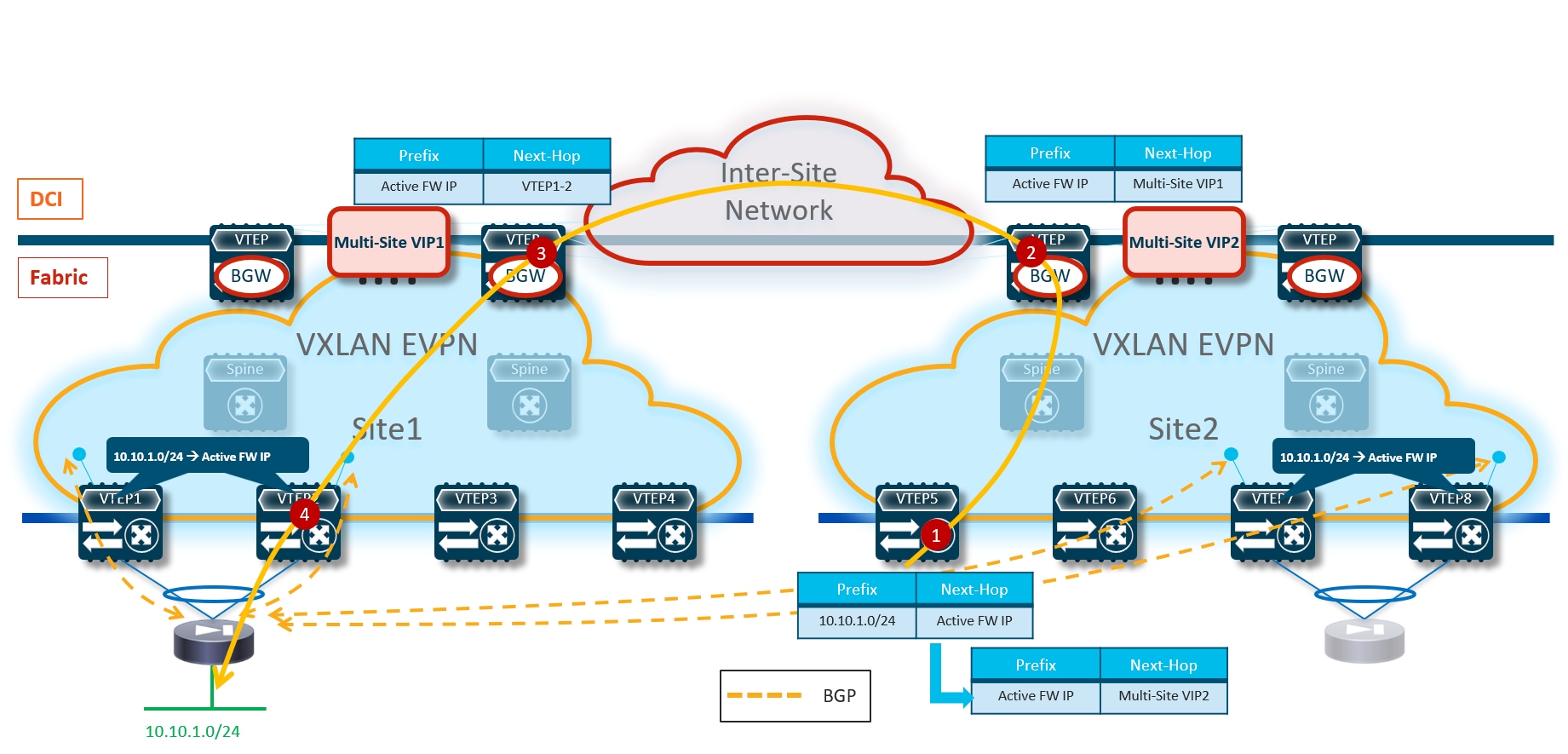
1. VTEP5 receives a packet destined to an host part of the subnet 10.10.1.0/24 connected behind the active firewall node deployed in Site1. The lookup in its routing table results in the active firewall IP address and the recursive lookup for the firewall address points to the Multi-Site VIP of the local BGW nodes.
2. The BGW nodes in Site2 performs the same recursive lookup and send the traffic to the BGW in Site1 (since the active firewall is connected in that site).
3. The BGW nodes in Site1 performs the same recursive lookup and send the traffic toward the service leaf nodes where the active firewall is locally connected.
4. The service leaf node receiving the traffic forwards it toward the active firewall.
As for the prefixes advertised in the opposite direction (from the service leaf nodes toward the active firewall), nothing needs to be configured to ensure the optimal handling of outbound traffic flows. The active firewall will receive those prefixes from the directly connected service leaf nodes and from the remote service leaf nodes. Assuming the firewall is deployed in its own BGP ASN and connectivity to the external network is available via local and remote border leaf nodes, the active firewall would have by default ECMP paths to reach the external prefix, pointing to the loopback interfaces of the local and remote service leaf nodes as next-hop address.
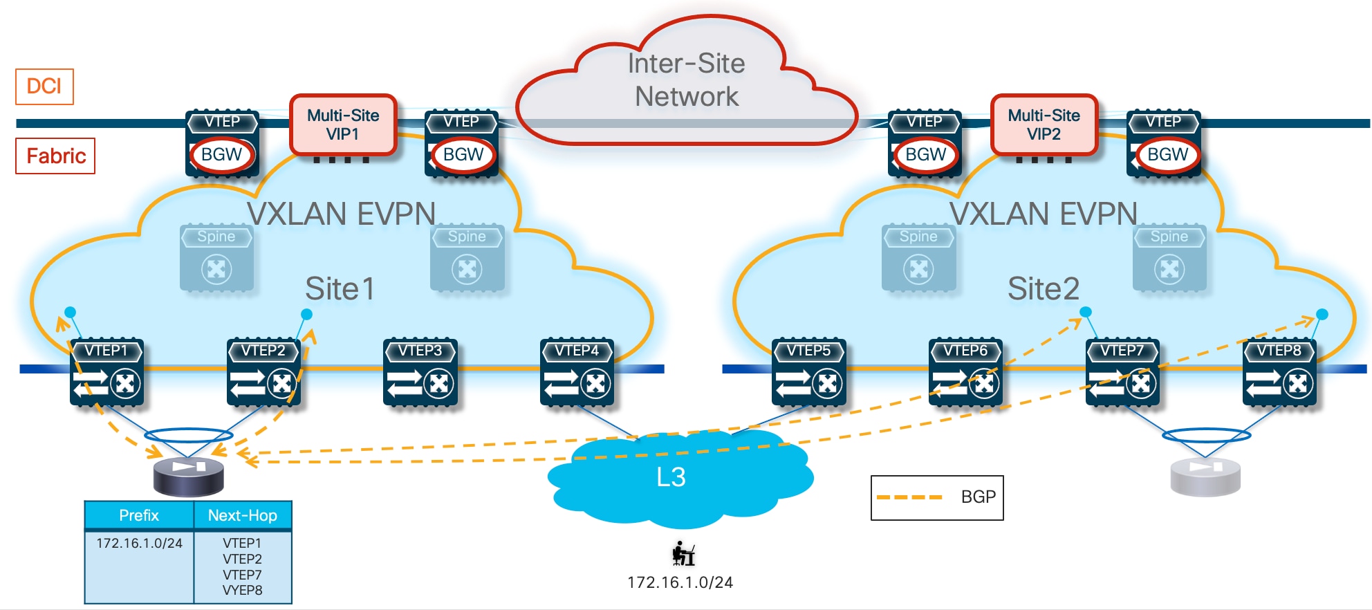
However, static routes are configured on the active firewall to reach those loopback IP addresses. The next-hop specified in the static routes is the anycast gateway address of the Service Network used to connect the firewall nodes to the fabric service leaf nodes. Therefore, the recursive lookup performed on the firewall would ensure that the destination MAC of the data-packet sent toward the fabric (and originated by an endpoint connected to one of the IP subnets behind the firewall) is always the fabric anycast gateway MAC. This implies that whichever locally connected service leaf node receives that frame, it will be able to locally route it toward the destination, independently from the original VTEP selected as next-hop by the firewall (Figure 33).
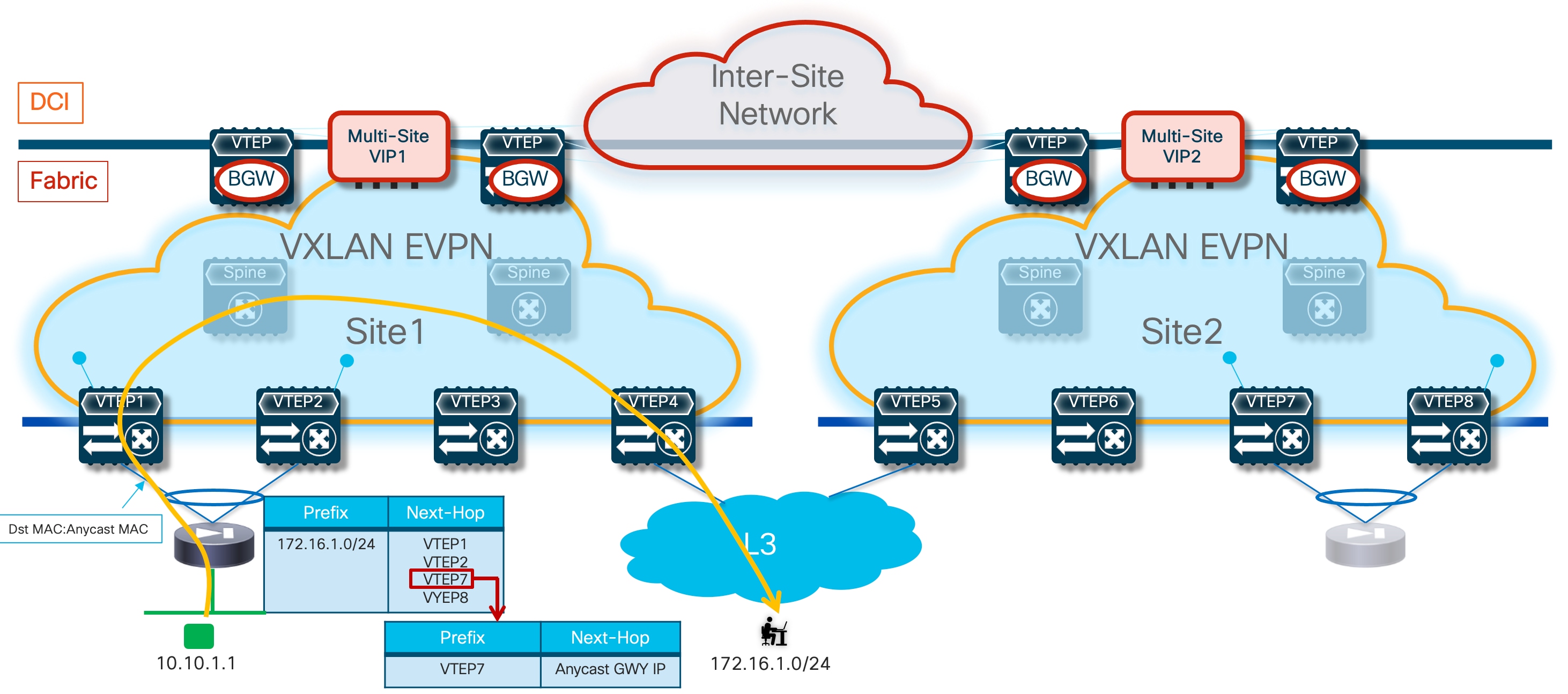
Despite the configuration tuning recommendations made above, it is obvious that the deployment of an Active/Standby firewall pair stretched across site would inevitably cause the hair-pinning of traffic. This applies not only to communication between endpoints deployed in different subnets and using the firewall as default gateway, but also for North-South connectivity (please refer to previous Figure 14). The deployment of an Active/Active firewall cluster in Split Spanned EtherChannel mode, discussed in the next section, provides a solution for the optimal handling of both types of traffic flows.
Configuration Samples
The samples below capture the configuration required on the service leaf nodes, the border gateway node, and the firewall, in the specific use case where the firewall is connected in vPC mode and establishes EBGP adjacencies with the local and remote service leaf nodes. The reference topology for all the configuration samples is shown below in Figure 34.
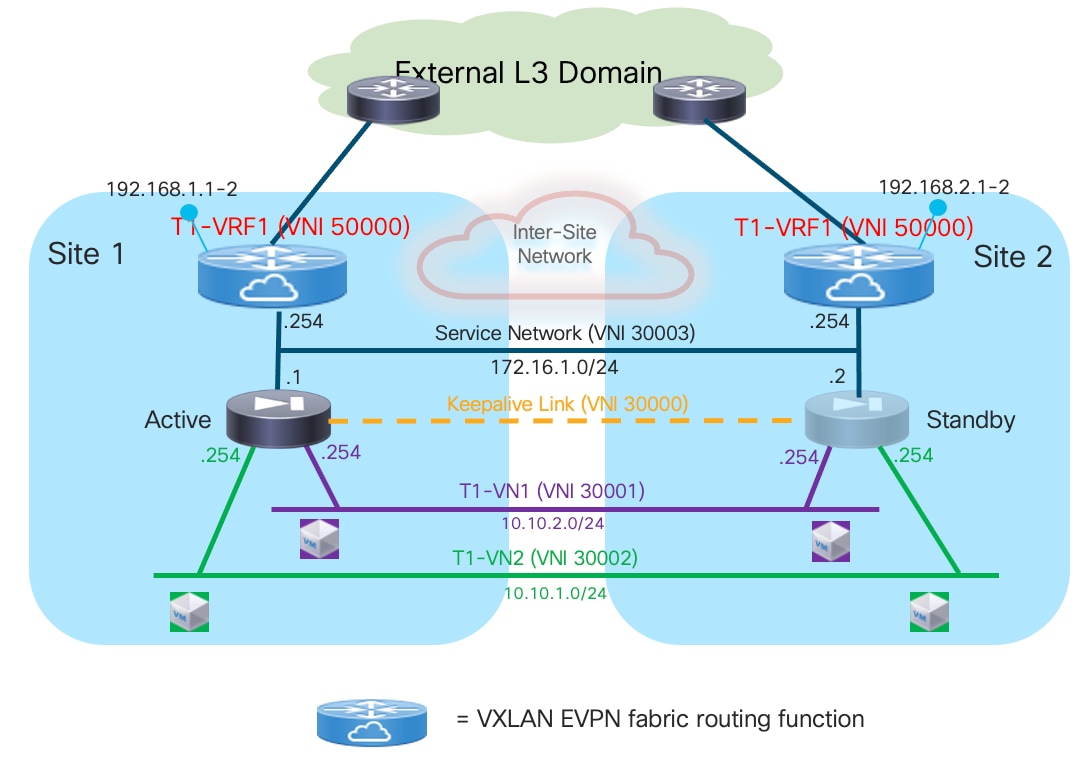
Compute Leaf Nodes
Define the L2VNI segments (Layer 2 only) representing the subnets where the endpoints are connected:
Vlan 2301
vn-segment 30001
!
vlan 2302
vn-segment 30002
!
interface nve1
member vni 30001
mcast-group 239.1.1.1
member vni 30002
mcast-group 239.1.1.1
!
evpn
vni 30001 l2
rd auto
route-target import auto
route-target export auto
vni 30002 l2
rd auto
route-target import auto
route-target export auto
!
interface port-channel1
description vPC to the ESXi host
switchport mode trunk
switchport trunk allowed vlan 2301-2302
spanning-tree port type edge trunk
spanning-tree bpduguard enable
mtu 9216
vpc 1
Service Leaf Nodes
On the leaf nodes where the active and standby service nodes are connected, define a VRF dedicated to each tenant and all the associated configurations to implement the northbound Layer 3 network. Notice the definition in the VRF of the loopback interface used to peer EBGP with the active firewall. The same configuration must be applied to the vPC pair of service leaf nodes where the active firewall node is connected and also to the vPC pair of service leaf nodes in the remote fabric where the standby firewall node is connected, with the only difference being the fabric’s specific BGP ASN value.
vlan 2000
vn-segment 50000
!
vrf context t1-vrf
vni 50000
rd auto
address-family ipv4 unicast
route-target both auto
route-target both auto evpn
address-family ipv6 unicast
route-target both auto
route-target both auto evpn
!
interface Vlan2000
no shutdown
mtu 9216
vrf member t1-vrf
no ip redirects
ip forward
ipv6 address use-link-local-only
no ipv6 redirects
!
interface loopback2
description Loopback to peer with the Active Firewall
vrf member t1-vrf
ip address 192.168.1.1/32 tag 12345
!
route-map fabric-rmap-redist-subnet permit 10
match tag 12345
!
router bgp 65001
vrf t1-vrf
address-family ipv4 unicast
advertise l2vpn evpn
redistribute direct route-map fabric-rmap-redist-subnet
maximum-paths ibgp 2
address-family ipv6 unicast
advertise l2vpn evpn
redistribute direct route-map fabric-rmap-redist-subnet
maximum-paths ibgp 2
!
interface nve1
member vni 50000 associate-vrf
Define the L2VNI segment used as firewall Keepalive Link (vn-segment 30000). The corresponding VLAN must then be trunked on the vPC connection toward the Firewall node.
Note: In this example, the endpoints L2VNIs (and associated SVIs) are not defined on the service leaf nodes, but that could obviously be the case if the logical roles of compute nodes and service leaf nodes are co-located on the same set of physical devices.
vlan 2300
vn-segment 30000
!
interface nve1
member vni 30000
mcast-group 239.1.1.1
!
evpn
vni 30000 l2
rd auto
route-target import auto
route-target export auto
!
interface port-channel1
description vPC to the Firewall Node
switchport mode trunk
switchport trunk allowed vlan 2300
spanning-tree port type edge trunk
spanning-tree bpduguard enable
mtu 9216
vpc 1
Define the Service Network used to connect the firewall nodes to the service leaf nodes. This is the transit network used to establish EBGP adjacencies between the active firewall and the loopback interfaces on the service leaf nodes (local and remote).
vlan 3000
vn-segment 30003
!
interface Vlan3000
description Service Network
no shutdown
vrf member t1-vrf
ip address 172.16.1.254/24 tag 12345
fabric forwarding mode anycast-gateway
!
interface nve1
member vni 30003
mcast-group 239.1.1.1
!
evpn
vni 30003 l2
rd auto
route-target import auto
route-target export auto
!
interface port-channel1
description vPC to the Firewall Node
switchport mode trunk
switchport trunk allowed vlan 2300,3000
Create the EBGP peerings between each service leaf node and the active firewall. Notice the use of the “export-gateway-ip” functionality to optimize the traffic flows destined to the endpoints’ subnets behind the firewall. Also, “advertise-pip” and “advertise-virtual-rmac” commands are required to ensure the active firewall can establish EBGP sessions with all the service leaf nodes (unless there are scalability concerns, this option is recommended instead of creating a per-VRF peering over the vPC peer-link).
router bgp 65001
router-id 10.1.1.1
address-family l2vpn evpn
advertise-pip
vrf t1-vrf
address-family ipv4 unicast
export-gateway-ip
neighbor 172.16.1.1
remote-as 65200
update-source loopback2
ebgp-multihop 10
address-family ipv4 unicast
send-community
send-community extended
!
interface nve1
advertise virtual-rmac
BGW Nodes
Define the VRF for each tenant and all the associated configurations to extend the VRFs between fabrics, including the use of “export-gateway-ip”. Note that the full BGW configuration is not shown below, so we recommend referencing the VXLAN Multi-Site documentation for more information.
Vlan 2000
vn-segment 50000
!
vrf context t1-vrf
vni 50000
rd auto
address-family ipv4 unicast
route-target both auto
route-target both auto evpn
address-family ipv6 unicast
route-target both auto
route-target both auto evpn
!
route-map fabric-rmap-redist-subnet permit 10
match tag 12345
!
router bgp 65001
vrf t1-vrf
address-family ipv4 unicast
advertise l2vpn evpn
redistribute direct route-map fabric-rmap-redist-subnet
maximum-paths ibgp 2
export-gateway-ip
address-family ipv6 unicast
advertise l2vpn evpn
redistribute direct route-map fabric-rmap-redist-subnet
maximum-paths ibgp 2
export-gateway-ip
!
interface nve1
member vni 50000 associate-vrf
!
evpn
vni 30000 l2
rd auto
route-target import auto
route-target export auto
Locally define the L2VNI segments used as firewall Keepalive Link to connect the endpoints and as Service Network to extend those networks across the fabrics.
vlan 2300
vn-segment 30000
!
vlan 2301
vn-segment 30001
!
vlan 2302
vn-segment 30002
!
vlan 3000
vn-segment 30003
!
interface nve1
host-reachability protocol bgp
source-interface loopback1
multisite border-gateway interface loopback100
member vni 30000
multisite ingress-replication
mcast-group 239.1.1.1
member vni 30001
multisite ingress-replication
mcast-group 239.1.1.1
member vni 30002
multisite ingress-replication
mcast-group 239.1.1.1
member vni 30003
multisite ingress-replication
mcast-group 239.1.1.1
!
evpn
vni 30000 l2
rd auto
route-target import auto
route-target export auto
vni 30001 l2
rd auto
route-target import auto
route-target export auto
vni 30002 l2
rd auto
route-target import auto
route-target export auto
vni 30003 l2
rd auto
route-target import auto
route-target export auto
Firewall Nodes
The configuration sample below is taken from a Cisco ASA model but can be easily adapted to apply to different types of firewall devices (physical or virtual form factors). We also assume that the required failover configuration has already been applied to build an Active/Standby firewall pair, as described in the previous “Active/Standby Firewall Cluster Stretched across Sites” section.
Configure the required inside and outside interfaces. A local port-channel interfaces (Port-channel2) is deployed on each firewall (assuming it is a physical appliance) to carry data interfaces. Sub-interfaces are created on this port-channel interface to forward traffic toward the endpoints’ subnets and toward the northbound Layer 3 device. BGP is also configured on the firewall to establish adjacencies with the loopback interfaces defined on the local and remote service leaf nodes. Static routes are required on the firewall to establish connectivity with those loopback interfaces. Also, a route to Null0 is created in the example below to ensure the firewall can advertise toward the fabric a summary prefix including the endpoints’ subnets.
interface Port-channel2.2301
vlan 2301
nameif inside-VLAN2301
security-level 100
ip address 10.10.1.254 255.255.255.0 standby 10.10.1.253
!
interface Port-channel2.2302
vlan 2302
nameif inside-VLAN2302
security-level 100
ip address 10.10.2.254 255.255.255.0 standby 10.10.2.253
!
interface Port-channel2.3000
vlan 3000
nameif outside
security-level 0
ip address 172.16.1.1 255.255.255.0 standby 172.16.1.2
!
router bgp 65200
address-family ipv4 unicast
neighbor 192.168.1.1 remote-as 65001
neighbor 192.168.1.1 ebgp-multihop 10
neighbor 192.168.1.1 activate
neighbor 192.168.1.2 remote-as 65001
neighbor 192.168.1.2 ebgp-multihop 10
neighbor 192.168.1.2 activate
neighbor 192.168.2.1 remote-as 65002
neighbor 192.168.2.1 ebgp-multihop 10
neighbor 192.168.2.1 activate
neighbor 192.168.2.2 remote-as 65002
neighbor 192.168.2.2 ebgp-multihop 10
neighbor 192.168.2.2 activate
network 10.10.0.0 mask 255.255.0.0
maximum-paths 4
no auto-summary
no synchronization
exit-address-family
!
route Null0 10.10.0.0 255.255.0.0 1
route outside 192.168.1.1 255.255.255.255 172.16.1.254 1
route outside 192.168.1.2 255.255.255.255 172.16.1.254 1
route outside 192.168.2.1 255.255.255.255 172.16.1.254 1
route outside 192.168.2.2 255.255.255.255 172.16.1.254 1
Active/Active Firewall Cluster as Default Gateway Stretched across Sites
The deployment of an Active/Active firewall cluster in Split Spanned EtherChannel mode represents the evolution of the Active/Standby option discussed in the previous section, as it allows you to simplify several aspects of the solution, especially for the use case where static routing is used between the firewall deployed as default gateway and the northbound network infrastructure.
In Cisco’s Active/Active firewall cluster implementation, any routing protocol only runs on the Master node, with the consequence that the prefixes are only advertised to the service leaf nodes directly connected to the Master node and this does not allow leveraging the multiple paths available via all the firewall nodes part of the same cluster. This is the reason why only the static approach is covered in this document for the specific use case where the firewall is deployed as default gateway.
Note: The deployment of an Active/Active cluster in Individual Interfaces mode does not apply to this specific use case and won’t be considered.
Use of Static Routing between the Firewall Nodes and the Leaf Nodes
Figure 35 shows the topology for the deployment of the Active/Active firewall cluster as default gateway when static routing is used to connect to the northbound network.
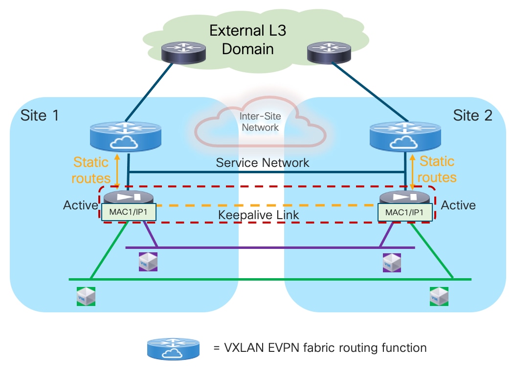
The same considerations made for the Active/Standby cluster about the networks that need to be extended also apply for the Active/Active use case, so they won’t be repeated here. Refer to the previous section for more details.
The first simplification introduced with the deployment of an Active/Active firewall cluster consists in removing the need to ensure that the traffic is always sent to the service leaf nodes connected to the active firewall. Because all the firewall nodes are active at the same time, the leaf nodes deployed in the fabrics where the firewall nodes are located always prefer to forward the traffic to the local service leaf nodes. This provides a distributed default gateway functionality for the endpoints that removes the hair-pinning of traffic experienced when stretching across fabrics an Active/Standby firewall cluster.
Figure 36 displays the traffic optimization achieved for both East-West and North-South flows due to the distributed default gateway functionality offered by the Active/Active firewall cluster (compare this with the behavior shown previously in Figure 14 for an Active/Standby cluster).
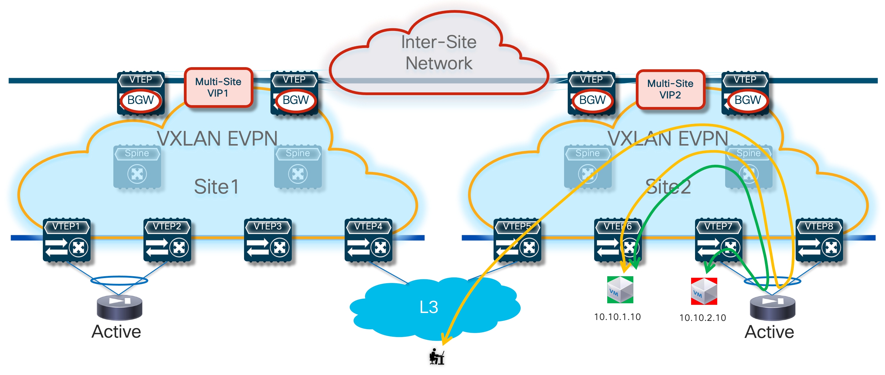
Additionally, the deployment of an Active/Active cluster removes the need to deploy one of the three options discussed for the Active/Standby cluster for optimizing the connectivity to the active firewall. Figure 37, when compared with previous Figure 15 shows how the inbound traffic flows can always be handled by a local firewall node independently from what inbound path they take.
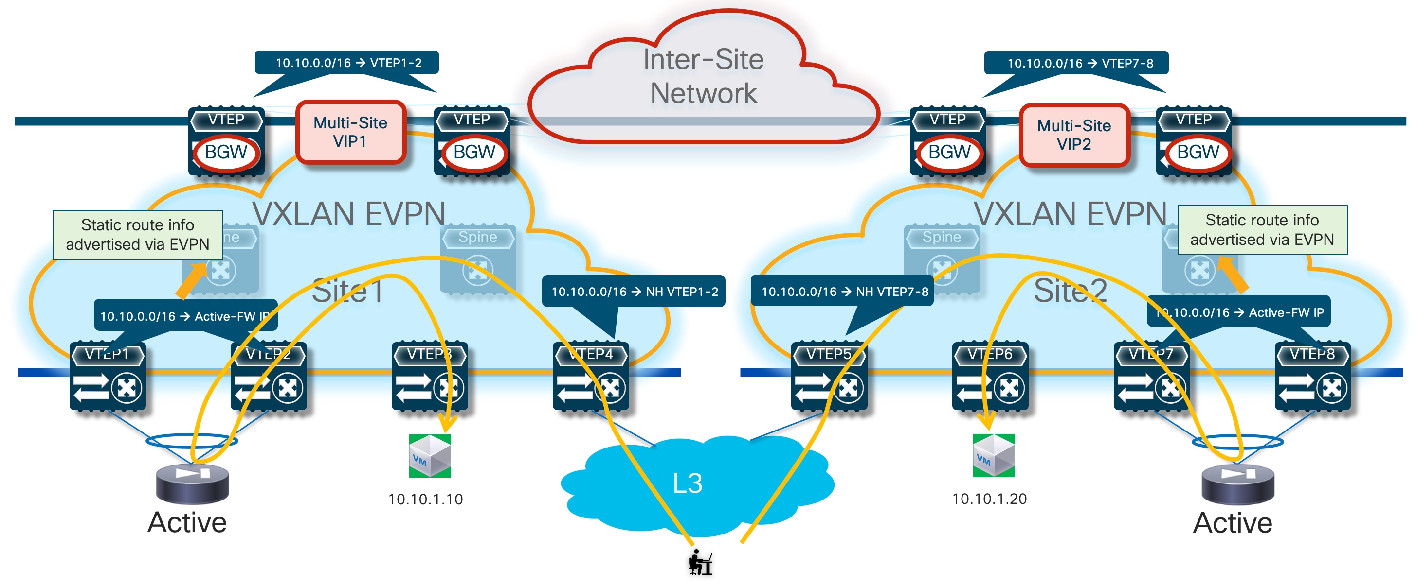
Note: in the example shown in figure above, inbound traffic destined to the endpoints part of the 10.10.1.0/24 stretched IP subnet is optimized. However, firewall devices usually do not support advertisement of host routes, so it may be the case that such inbound optimization is not possible. In any case, the deployment pf a stretched Active/Active firewall cluster would handle communication even in a not-optimized scenario.
Configuration Samples
The samples below capture the configuration required on the service leaf nodes, the border gateway node, and the firewall. In the specific use case where the firewall nodes are part of the Active/Active cluster, a single vPC connection must be used by all the firewall nodes deployed in the same fabric. Refer to the “Split Spanned EtherChannels Active/Active Firewall Cluster Mode” section for more information on how to build an Active/Active cluster and how to ensure that the same MAC/IP pair owned by all the firewall nodes part of the cluster can be simultaneously learned in different fabrics without being considered a MAC/IP move event.
The reference topology for all the configuration samples is the one shown in Figure 38:
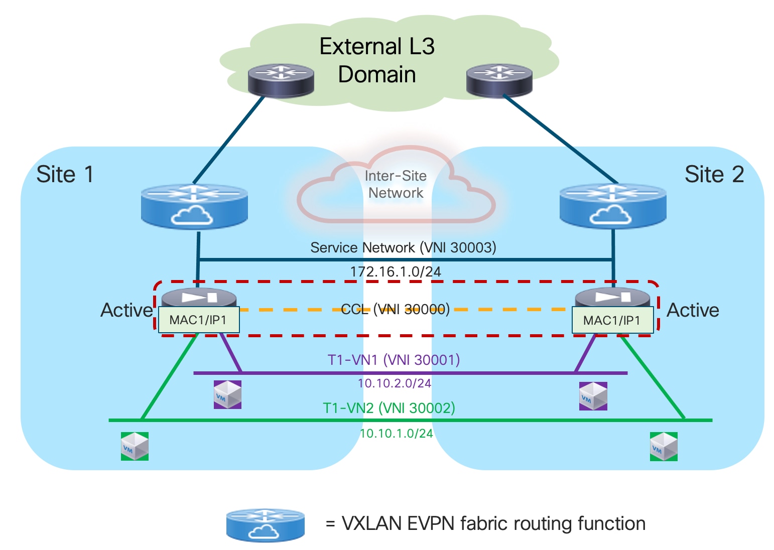
Compute Leaf Nodes
Define the L2VNI segments (Layer 2 only) representing the subnets where the endpoints are connected.
vlan 2301
vn-segment 30001
!
vlan 2302
vn-segment 30002
!
interface nve1
member vni 30001
mcast-group 239.1.1.1
member vni 30002
mcast-group 239.1.1.1
!
evpn
vni 30001 l2
rd auto
route-target import auto
route-target export auto
vni 30002 l2
rd auto
route-target import auto
route-target export auto
!
interface port-channel1
description vPC to the ESXi host
switchport mode trunk
switchport trunk allowed vlan 2301-2302
spanning-tree port type edge trunk
spanning-tree bpduguard enable
mtu 9216
vpc 1
Service Leaf Nodes
On the leaf nodes where the firewall nodes are connected, define a VRF dedicated to each tenant and all the associated configurations to implement the northbound Layer 3 network. Notice the definition of the static route under the VRF and how to redistribute it into the EVPN control plane. In this simple example, the subnets for the endpoints are all summarized with a /16 super-net (10.10.0.0/16), whereas 172.16.1.1 represents the IP address owned by all the firewall nodes. The same configuration must be applied on the service leaf nodes in the remote fabrics where the firewall nodes part of the same Active/Active cluster are connected, with the only difference being the fabric’s specific BGP ASN value.
vlan 2000
vn-segment 50000
!
vrf context t1-vrf
vni 50000
ip route 10.10.0.0/16 172.16.1.1 tag 12345
rd auto
address-family ipv4 unicast
route-target both auto
route-target both auto evpn
address-family ipv6 unicast
route-target both auto
route-target both auto evpn
!
interface Vlan2000
no shutdown
mtu 9216
vrf member t1-vrf
no ip redirects
ip forward
ipv6 address use-link-local-only
no ipv6 redirects
!
router bgp 65001
vrf t1-vrf1
address-family ipv4 unicast
advertise l2vpn evpn
redistribute static route-map redist-static-routes
maximum-paths ibgp 2
address-family ipv6 unicast
advertise l2vpn evpn
redistribute static route-map redist-static-routes
maximum-paths ibgp 2
!
interface nve1
member vni 50000 associate-vrf
Define the L2VNI segment used as firewall Cluster Control Link – CCL (vn-segment 30000). The corresponding VLAN must then be trunked on the vPC connections toward the firewall nodes.
Note: In this example, the endpoints L2VNIs (and associated SVIs) are not defined on the service leaf nodes, but that could obviously be the case if the logical roles of compute nodes and service leaf nodes are co-located on the same set of physical devices.
vlan 2300
vn-segment 30000
!
interface nve1
member vni 30000
mcast-group 239.1.1.1
!
evpn
vni 30000 l2
rd auto
route-target import auto
route-target export auto
!
interface port-channel1
description vPC to the Firewall Nodes
switchport mode trunk
switchport trunk allowed vlan 2300
spanning-tree port type edge trunk
spanning-tree bpduguard enable
mtu 9216
vpc 1
ethernet-segment vpc
esi 0012.0000.0000.1200.0102 tag 1012
Define the Service Network used to connect the firewall nodes to the service leaf nodes. For this L2VNI, it is also required to define an anycast gateway address, which represents the next-hop of the static default route defined on the master firewall node and installed also on all the slave nodes (see config sample later below).
Vlan 3000
vn-segment 30003
!
interface Vlan3000
description Service Network
no shutdown
vrf member t1-vrf
ip address 172.16.1.254/24 tag 12345
fabric forwarding mode anycast-gateway
!
interface nve1
member vni 30003
mcast-group 239.1.1.1
!
evpn
vni 30003 l2
rd auto
route-target import auto
route-target export auto
!
interface port-channel1
description vPC to the Firewall Node
switchport mode trunk
switchport trunk allowed vlan 2300,3000
BGW Nodes
Define the VRF for each tenant and all the associated configurations to extend the VRFs between fabrics. Note that the full BGW configuration is not shown below, so we recommend referencing the VXLAN Multi-Site documentation for more information, starting with the following white paper:
https://www.cisco.com/c/en/us/products/collateral/switches/nexus-9000-series-switches/white-paper-c11-739942.html
vlan 2000
vn-segment 50000
!
vrf context t1-vrf
vni 50000
rd auto
address-family ipv4 unicast
route-target both auto
route-target both auto evpn
address-family ipv6 unicast
route-target both auto
route-target both auto evpn
!
route-map fabric-rmap-redist-subnet permit 10
match tag 12345
!
router bgp 65001
vrf t1-vrf
address-family ipv4 unicast
advertise l2vpn evpn
redistribute direct route-map fabric-rmap-redist-subnet
maximum-paths ibgp 2
export-gateway-ip
address-family ipv6 unicast
advertise l2vpn evpn
redistribute direct route-map fabric-rmap-redist-subnet
maximum-paths ibgp 2
export-gateway-ip
!
interface nve1
member vni 50000 associate-vrf
!
evpn
vni 30000 l2
rd auto
route-target import auto
route-target export auto
Locally define the L2VNI segments used as firewall cluster CCL to connect the endpoints and as Service Network to extend those networks across the fabrics.
vlan 2300
vn-segment 30000
!
vlan 2301
vn-segment 30001
!
vlan 2302
vn-segment 30002
!
vlan 3000
vn-segment 30003
!
interface nve1
host-reachability protocol bgp
source-interface loopback1
multisite border-gateway interface loopback100
member vni 30000
multisite ingress-replication
mcast-group 239.1.1.1
member vni 30001
multisite ingress-replication
mcast-group 239.1.1.1
member vni 30002
multisite ingress-replication
mcast-group 239.1.1.1
member vni 30003
multisite ingress-replication
mcast-group 239.1.1.1
!
evpn
vni 30000 l2
rd auto
route-target import auto
route-target export auto
vni 30001 l2
rd auto
route-target import auto
route-target export auto
vni 30002 l2
rd auto
route-target import auto
route-target export auto
vni 30003 l2
rd auto
route-target import auto
route-target export auto
Firewall Nodes
The configuration sample below is taken from a Cisco ASA model, and it must be applied on the Master node so that can then be replicated to all the Slave nodes as well.
Configure the required inside and outside interfaces. A local port-channel interfaces (Port-channel2) is deployed on each firewall to carry data interfaces. Sub-interfaces are created on this port-channel interface to forward traffic toward the endpoints’ subnets and toward the northbound Layer 3 device. A default static route pointing to the anycast gateway IP address defined on the service leaf nodes for the Service Network segment is used to forward northbound all traffic destined to any destination external to the specific tenant/VRF domain.
interface Port-channel2.2301
vlan 2301
nameif inside-VLAN2301
security-level 100
ip address 10.10.1.254 255.255.255.0 standby 10.10.1.253
!
interface Port-channel2.2302
vlan 2302
nameif inside-VLAN2302
security-level 100
ip address 10.10.2.254 255.255.255.0 standby 10.10.2.253
!
interface Port-channel2.3000
vlan 3000
nameif outside
security-level 0
ip address 172.16.1.1 255.255.255.0 standby 172.16.1.2
!
access-list permit-any extended permit ip any any
access-group permit-any in interface outside
!
route outside 0.0.0.0 0.0.0.0 172.16.1.254 1
Default Gateway on the Fabric, Edge Firewall Connected to the Fabric
In contrast to the use case where the firewall is deployed as default gateway for the endpoints, in this specific scenario (highlighted in Figure 39) the entire VRF routing domain is considered as a security zone. Traffic flows are sent to the firewall front-ending the VRF only if/when there is a need to communicate with an entity outside of the VRF domain. This is the case for North-South communication with the external network domain, or for East-West communication between endpoints belonging to different Tenants/VRFs.
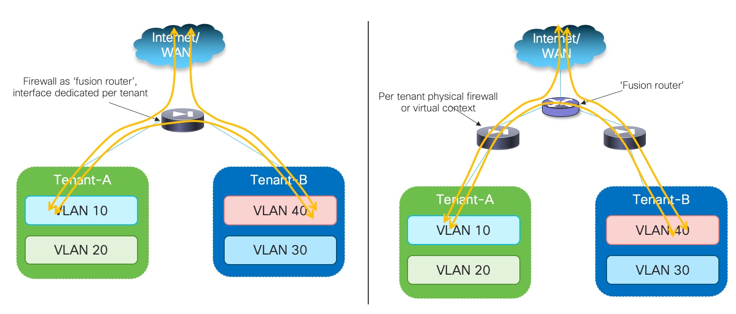
The figure above also shows a couple of different options for the deployment of the “fusion function” allowing to establish inter-tenant communication and North-South communication between each tenant and the external network domain: on the left, the firewall functions as a “fusion” router and its interfaces are dedicated for connecting to each tenant’s specific security zone. In the deployment model on the right, each tenant/VRF is front ended by a dedicated firewall device (physical or logical) and the “fusion” function is performed by a separate northbound device. The latter option is usually the preferred one in a multi-tenant design as it allows to apply tenant’s specific security policies on each dedicated firewall instance, minimizing the risk of mistakes that may open undesired inter-tenant communication.
When it comes to the physical connectivity of the firewall nodes with the fabric, many real-life deployments leverage a single set of interfaces (using vPC or port-channel straight-through options) and different VLANs to logically represent the inside and outside interfaces. In such scenario, a typical deployment model consists in “sandwiching” the firewall device between two VRFs defined on the service leaf nodes, the first VRF providing connectivity to the Tenant/VRF resources, the second to the northbound network domain. This model is the one discussed in this section of the paper, but most of the considerations made here apply also to the use case where the firewall device peers directly northbound with an external Layer 3 network.
Using static routing is not a viable approach in this case, therefore the recommended and documented approach is using EBGP on the firewall device to peer with the northbound and southbound VRFs.
Active/Standby Edge Firewall Cluster Stretched across Sites
As it was done for the firewall as default gateway use case, the first redundancy model that is considered is the one where an Active/Standby firewall cluster is stretched across sites.
VRF Sandwich Design and Firewall Dynamically Peering with the Leaf Nodes
A logical representation of the “VRF sandwich design” is shown in Figure 40 below.
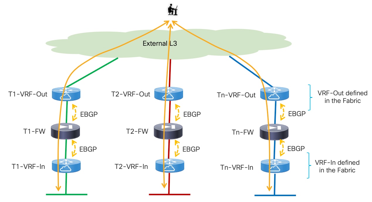
As previously mentioned, two VRFs are assigned to each tenant: the internal VRF represents the security zone where all the tenant’s endpoints are connected and provides switching and routing capabilities between the endpoints’ subnets. The external VRF is used to connect each specific tenant with other tenants or with the external network domain. The firewall service node is stitched in between the two VRFs to provide the security policy enforcements for all the traffic flows entering/leaving the tenant’s security zone.
The external VRF could be unique for each tenant, as in the example above, when the main goal is to maintain the logical isolation of traffic between different tenants also in the northbound network infrastructure. A specific “Shared VRF-Out” routing instance can be defined instead to allow for the establishment of East-West inter-tenant communication or to allow different tenants to access shared external network resources (like the Internet). This specific deployment model is highlighted in Figure 41.
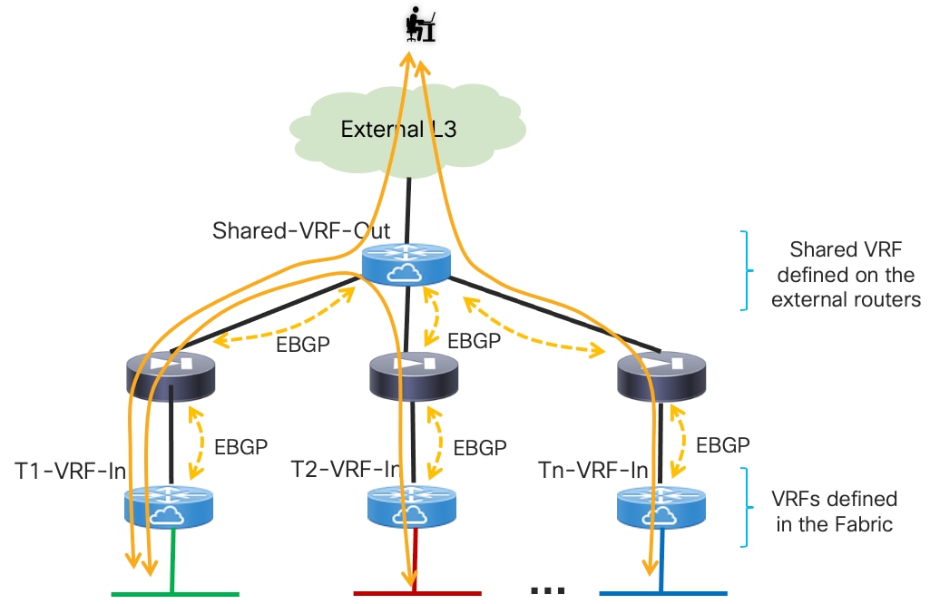
The deployment model discussed in this section of the paper builds on top of the design discussed in the “EBGP Peering between the Firewall and the Leaf Nodes” section. When comparing previous Figure 24 with Figure 42 below, you can notice how the active firewall node now establishes EBGP adjacencies with the loopback interfaces of the service leaf nodes (both local and remote) via both the outside and the inside interfaces (because the firewall is not anymore the default gateway for the endpoints).
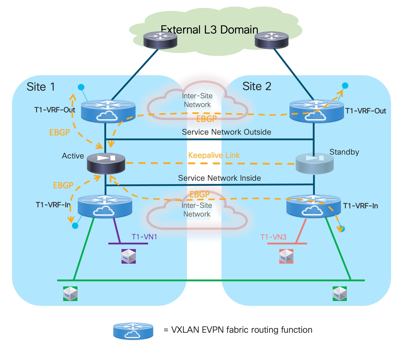
Most of the deployment considerations discussed in the firewall as default gateway use case continue to apply also to this scenario, so please reference to the “Dynamic Peering between the Active and the Service Leaf Nodes” section for more information.
The active firewall node should establish multi-hop EBGP sessions with both the local (i.e. directly connected) and remote service leaf nodes, or better with unique loopback interfaces defined on those leaf nodes. This is important to minimize the traffic outage during a firewall switchover event. As it will be shown in the configuration samples below, because the active firewall node peers with two VRFs defined in the same fabric, it is required to introduce the use of “local-as” on the BGP configuration of the service leaf nodes to ensure the firewall can peer with a different BGP ASNs northbound and southbound, therefore allowing the successful exchange of prefixes between the inside and outside VRFs.
The different networks shown in Figure 42 should be stretched across sites leveraging the Layer 2 extension capabilities offered by VXLAN Multi-Site. This applies to endpoints’ subnets extended across fabrics, the Service Networks Inside and Outside (used to establish the EBGP adjacencies between the firewall and the VRFs in the fabric) and the L2VNI segment used for the exchange of keepalives between active and standby firewall nodes.
When the firewall nodes are connected to the service leaf nodes using vPC (with or without the use of the physical peer-link), it is required and recommended to enable “advertise-pip” on the service leaf nodes to ensure that reachability to the loopbacks of all the service leaf nodes is always possible independently from what physical path is used to establish those EBGP sessions. A less desirable technical alternative is to establish a per-VRF Layer 3 peering via the vPC peer-link.
Because the active firewall establishes EBGP adjacencies with both the local and remote service leaf nodes, “export-gateway-ip” must be configured under the BGP process to ensure that traffic flows that need to go through the firewall are always encapsulated to the service leaf nodes directly connected to the active firewall. By enabling that functionality, the active firewall IP address is always installed as next-hop for the prefixes injected into the fabric by the service leaf nodes. Using recursive routing, all the leaf nodes in the multi-fabric domain always encapsulate traffic to the service leaf nodes that have advertised the firewall IP address as directly connected.
As the last consideration, the use of an Active/Standby device pair as a perimeter firewall service deployed across sites is subjected to the same traffic hair-pinning considerations for both inter-tenant connectivity (East-West) and for North-South connectivity between a given tenant and the external network domain. The deployment of an Active/Active firewall cluster in Individual Interface mode, discussed in the next section, provides an alternative model aiming to optimize both types of traffic flows.
Configuration Samples
The samples below capture the configuration required on the compute leaf nodes, service leaf nodes, border gateway nodes, and the firewalls, in the specific example where the firewall is connected in vPC mode (the reference topology is displayed in Figure 43).
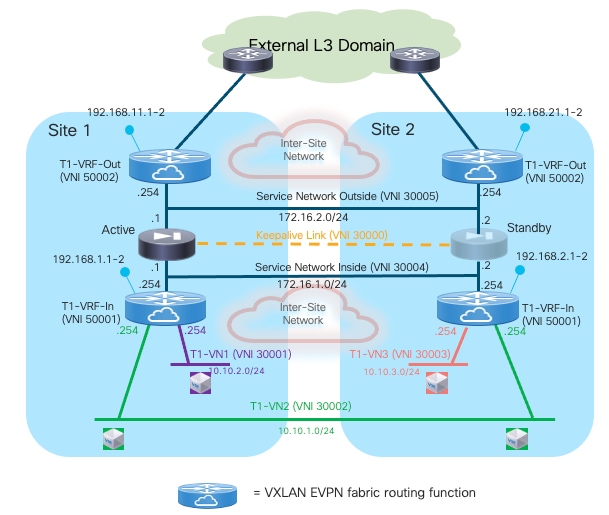
Compute Leaf Nodes
Define the inside VRF for a specific tenant and the L2VNI segments (inclusive of SVIs to implementing the anycast default gateway function) representing the subnets where the endpoints are connected.
vlan 2001
vn-segment 50001
!
vlan 2301
vn-segment 30001
!
vlan 2302
vn-segment 30002
!
vrf context t1-vrf-in
vni 50001
rd auto
address-family ipv4 unicast
route-target both auto
route-target both auto evpn
address-family ipv6 unicast
route-target both auto
route-target both auto evpn
!
interface Vlan2001
no shutdown
mtu 9216
vrf member t1-vrf-in
no ip redirects
ip forward
ipv6 address use-link-local-only
no ipv6 redirects
!
interface Vlan2301
no shutdown
vrf member t1-vrf-in
ip address 10.10.1.254/24 tag 12345
fabric forwarding mode anycast-gateway
!
interface Vlan2302
no shutdown
vrf member t1-vrf-in
ip address 10.10.2.254/24 tag 12345
fabric forwarding mode anycast-gateway
!
interface nve1
member vni 30001
mcast-group 239.1.1.1
member vni 30002
mcast-group 239.1.1.1
member vni 50001 associate-vrf
!
route-map fabric-rmap-redist-subnet permit 10
match tag 12345
!
router bgp 65001
vrf t1-vrf-in
address-family ipv4 unicast
advertise l2vpn evpn
redistribute direct route-map fabric-rmap-redist-subnet
maximum-paths 4
address-family ipv6 unicast
advertise l2vpn evpn
redistribute direct route-map fabric-rmap-redist-subnet
maximum-paths 4
evpn
vni 30001 l2
rd auto
route-target import auto
route-target export auto
vni 30002 l2
rd auto
route-target import auto
route-target export auto
!
interface port-channel1
description vPC to the ESXi host
switchport mode trunk
switchport trunk allowed vlan 2301-2302
spanning-tree port type edge trunk
spanning-tree bpduguard enable
mtu 9216
vpc 1
Service Leaf Nodes
Define the inside and outside VRFs for a specific tenant and its associated configuration (including the loopback interfaces for EBGP peering).
vlan 2001
vn-segment 50001
!
vlan 2002
vn-segment 50002
!
vrf context t1-vrf-in
vni 50001
rd auto
address-family ipv4 unicast
route-target both auto
route-target both auto evpn
address-family ipv6 unicast
route-target both auto
route-target both auto evpn
!
vrf context t1-vrf-out
vni 50002
rd auto
address-family ipv4 unicast
route-target both auto
route-target both auto evpn
address-family ipv6 unicast
route-target both auto
route-target both auto evpn
!
interface Vlan2001
no shutdown
mtu 9216
vrf member t1-vrf-in
no ip redirects
ip forward
ipv6 address use-link-local-only
no ipv6 redirects
!
interface Vlan2002
no shutdown
mtu 9216
vrf member t1-vrf-out
no ip redirects
ip forward
ipv6 address use-link-local-only
no ipv6 redirects
!
interface loopback2
vrf member t1-vrf-in
ip address 192.168.1.1/32 tag 12345
!
interface loopback3
vrf member t1-vrf-out
ip address 192.168.11.1/32 tag 12345
!
route-map fabric-rmap-redist-subnet permit 10
match tag 12345
!
router bgp 65001
vrf t1-vrf-in
address-family ipv4 unicast
advertise l2vpn evpn
redistribute direct route-map fabric-rmap-redist-subnet
maximum-paths 4
address-family ipv6 unicast
advertise l2vpn evpn
redistribute direct route-map fabric-rmap-redist-subnet
maximum-paths 4
vrf t1-vrf-out
address-family ipv4 unicast
advertise l2vpn evpn
redistribute direct route-map fabric-rmap-redist-subnet
maximum-paths 4
address-family ipv6 unicast
advertise l2vpn evpn
redistribute direct route-map fabric-rmap-redist-subnet
maximum-paths 4
!
interface nve1
member vni 50001 associate-vrf
member vni 50002 associate-vrf
Define the L2VNI segment used as firewall Keepalive Link (vn-segment 30000, Layer-2 only).
Note: In this example, the endpoints L2VNIs (and associated SVIs) are not defined on the service leaf nodes, but that could obviously be the case if the logical roles of compute nodes and service leaf nodes are co-located on the same set of physical devices.
vlan 2300
vn-segment 30000
!
interface nve1
member vni 30000
mcast-group 239.1.1.1
!
evpn
vni 30000 l2
rd auto
route-target import auto
route-target export auto
!
interface port-channel1
description vPC to the Firewall Node
switchport mode trunk
switchport trunk allowed vlan 2300
spanning-tree port type edge trunk
spanning-tree bpduguard enable
mtu 9216
vpc 1
Define the Service Networks used to connect the firewall nodes to the service leaf nodes (on both the firewall’s inside and outside interfaces). Those are the transit networks used to establish EBGP adjacencies between the active firewall and the loopback interfaces on the service leaf nodes (local and remote) for both the inside and outside VRFs.
vlan 3004
vn-segment 30004
!
vlan 3005
vn-segment 30005
!
interface Vlan3004
no shutdown
vrf member t1-vrf-in
ip address 172.16.1.254/24 tag 12345
fabric forwarding mode anycast-gateway
!
interface Vlan3005
no shutdown
vrf member t1-vrf-out
ip address 172.16.2.254/24 tag 12345
fabric forwarding mode anycast-gateway
!
interface nve1
member vni 30004
mcast-group 239.1.1.1
member vni 30005
mcast-group 239.1.1.1
!
evpn
vni 30004 l2
rd auto
route-target import auto
route-target export auto
vni 30005 l2
rd auto
route-target import auto
route-target export auto
!
interface port-channel
description vPC to the Firewall Node
switchport mode trunk
switchport trunk allowed vlan 2300,3004-3005
Create the EBGP peerings between the service leaf node and the active firewall, for both the inside and the outside VRFs. Notice the use of the “export-gateway-ip” functionality to optimize the traffic flows destined to the endpoints’ subnets behind the firewall. Also, “advertise-pip” and “advertise-virtual-rmac” commands are required to ensure the active firewall can establish EBGP sessions with all the service leaf nodes (as previously mentioned, creating a per-VRF peering over the vPC peer-link is an alternative option).
Because the firewall nodes peer with the inside and outside VRF of each fabric, you are required to use the “local-as” configuration so that the firewall peers with two different ASNs (one for each VRF) and can propagate by default learned prefixes between them (Figure 44).
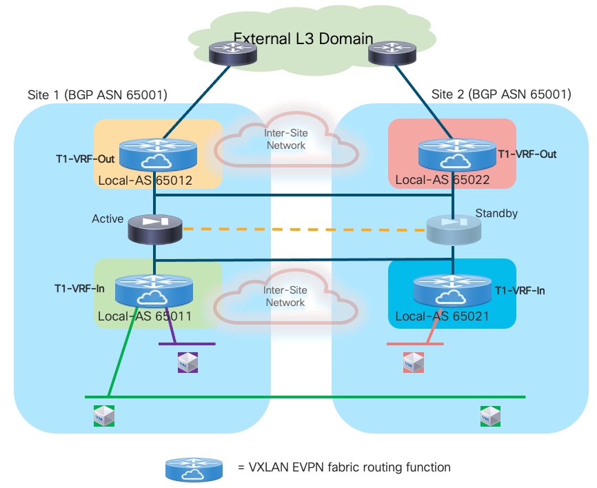
Note: In the service leaf node configuration sample below, the configuration of “local-as” is done per-neighbor (i.e. applies to the BGP adjacencies established between the service leaf nodes and the outside and inside interfaces of the firewall). When doing that, two ASNs are used by default in each VRF when sending prefixes to a neighbor, the global ASN (specified as part of the “router bgp 65001” command) and the “local-as” associated to the neighbor. In this case, the “no-prepend replace-as“ options should be added to the command to ensure that only the ASN specified in the “local-as” command is added to the prefixes advertised to the firewall. Alternatively, it would be possible to configure “local-as” globally at the VRF level (under BGP), in which casethe configuration would apply to all the BGP sessions configured in that VRF and only the specified local-as would be associated to the VRF and no additional configuration options are required.
router bgp 65001
router-id 10.12.0.2
address-family l2vpn evpn
advertise-pip
vrf t1-vrf-in
address-family ipv4 unicast
maximum-paths 4
export-gateway-ip
neighbor 172.16.1.1
local-as 65011 no-prepend replace-as
remote-as 65200
update-source loopback3
ebgp-multihop 10
address-family ipv4 unicast
send-community
send-community extended
vrf t1-vrf-out
address-family ipv4 unicast
maximum-paths 4
export-gateway-ip
neighbor 172.16.2.1
local-as 65012 no-prepend replace-as
remote-as 65200
update-source loopback2
ebgp-multihop 10
address-family ipv4 unicast
send-community
send-community extended
!
interface nve1
advertise virtual-rmac
BGW Nodes
Define the VRF for each tenant and all the associated configurations to extend the inside and outside VRFs between fabrics, including the use of “export-gateway-ip”. Note that the full BGW configuration is not shown below, please reference to the VXLAN Multi-Site documentation for more information.
vlan 2001
vn-segment 50001
!
vlan 2002
vn-segment 50002
!
vrf context t1-vrf-in
vni 50001
rd auto
address-family ipv4 unicast
route-target both auto
route-target both auto evpn
maximum-paths 4
export-gateway-ip
address-family ipv6 unicast
route-target both auto
route-target both auto evpn
maximum-paths 4
export-gateway-ip
!
vrf context t1-vrf-out
vni 50002
rd auto
address-family ipv4 unicast
route-target both auto
route-target both auto evpn
maximum-paths 4
export-gateway-ip
address-family ipv6 unicast
route-target both auto
route-target both auto evpn
maximum-paths 4
export-gateway-ip
!
interface Vlan2001
no shutdown
mtu 9216
vrf member t1-vrf-in
no ip redirects
ip forward
ipv6 address use-link-local-only
no ipv6 redirects
!
interface Vlan2002
no shutdown
mtu 9216
vrf member t1-vrf-out
no ip redirects
ip forward
ipv6 address use-link-local-only
no ipv6 redirects
!
interface nve1
member vni 50001 associate-vrf
member vni 50002 associate-vrf
Locally define the L2VNI segments used as firewall Keepalive Link to connect the endpoints and as Service Networks to extend those networks across the fabrics.
vlan 2300
vn-segment 30000
!
vlan 2301
vn-segment 30001
!
vlan 2302
vn-segment 30002
!
vlan 3004
vn-segment 30004
!
vlan 3005
vn-segment 30005
!
interface nve1
host-reachability protocol bgp
source-interface loopback1
multisite border-gateway interface loopback100
member vni 30000
multisite ingress-replication
mcast-group 239.1.1.1
member vni 30001
multisite ingress-replication
mcast-group 239.1.1.1
member vni 30002
multisite ingress-replication
mcast-group 239.1.1.1
member vni 30004
multisite ingress-replication
mcast-group 239.1.1.1
member vni 30005
multisite ingress-replication
mcast-group 239.1.1.1
!
evpn
vni 30000 l2
rd auto
route-target import auto
route-target export auto
vni 30001 l2
rd auto
route-target import auto
route-target export auto
vni 30002 l2
rd auto
route-target import auto
route-target export auto
vni 30004 l2
rd auto
route-target import auto
route-target export auto
vni 30005 l2
rd auto
route-target import auto
route-target export auto
Firewall Nodes
The configuration sample below is taken from a Cisco ASA model, but can be easily adapted to apply to different types of firewall devices (physical or virtual form factors). We also assume that the required failover configuration has already been applied to build an Active/Standby firewall pair, as described in the previous “Active/Standby Firewall Cluster Stretched across Sites” section.
Configure the required inside and outside interfaces. A local port-channel interfaces (Port-channel2) is deployed on each firewall (assuming it is a physical appliance) to carry data interfaces. Sub-interfaces are created on this port-channel interface to forward traffic toward the endpoints’ subnets and toward the northbound Layer 3 device. BGP is also configured on the firewall to establish adjacencies with the loopback interfaces defined on the local and remote service leaf nodes on both the inside and outside interfaces. Static routes are required on the firewall to establish connectivity with those loopback interfaces.
interface Port-channel2.3004
vlan 3004
nameif inside
security-level 100
ip address 172.16.1.254 255.255.255.0 standby 172.16.1.253
!
interface Port-channel2.3005
vlan 3005
nameif outside
security-level 0
ip address 172.16.2.254 255.255.255.0 standby 172.16.2.253
!
router bgp 65200
address-family ipv4 unicast
neighbor 192.168.1.1 remote-as 65011
neighbor 192.168.1.1 ebgp-multihop 10
neighbor 192.168.1.1 activate
neighbor 192.168.1.2 remote-as 65011
neighbor 192.168.1.2 ebgp-multihop 10
neighbor 192.168.1.2 activate
neighbor 192.168.2.1 remote-as 65021
neighbor 192.168.2.1 ebgp-multihop 10
neighbor 192.168.2.1 activate
neighbor 192.168.2.2 remote-as 65021
neighbor 192.168.2.2 ebgp-multihop 10
neighbor 192.168.2.2 activate
neighbor 192.168.11.1 remote-as 65012
neighbor 192.168.11.1 ebgp-multihop 10
neighbor 192.168.11.1 activate
neighbor 192.168.11.2 remote-as 65012
neighbor 192.168.11.2 ebgp-multihop 10
neighbor 192.168.11.2 activate
neighbor 192.168.21.1 remote-as 65022
neighbor 192.168.21.1 ebgp-multihop 10
neighbor 192.168.21.1 activate
neighbor 192.168.21.2 remote-as 65022
neighbor 192.168.21.2 ebgp-multihop 10
neighbor 192.168.21.2 activate
maximum-paths 4
no auto-summary
no synchronization
exit-address-family
!
route inside 192.168.1.1 255.255.255.255 172.16.1.1 1
route inside 192.168.1.2 255.255.255.255 172.16.1.1 1
route inside 192.168.2.1 255.255.255.255 172.16.1.1 1
route inside 192.168.2.2 255.255.255.255 172.16.1.1 1
route outside 192.168.11.1 255.255.255.255 172.16.2.1 1
route outside 192.168.11.2 255.255.255.255 172.16.2.1 1
route outside 192.168.21.1 255.255.255.255 172.16.2.1 1
route outside 192.168.21.2 255.255.255.255 172.16.2.1 1
Independent Edge Firewall Service Deployed per Site
This use case builds on top of the one just discussed, as the only difference is that instead of stretching an Active/Standby firewall cluster across sites, in this case a separate firewall service is deployed in each fabric. While losing the centralized configuration and policy management characteristics of the Active/Standby firewall model, this approach offers the capabilities of optimally handling the East-West and North-South traffic flows and provides more flexibility about the type of firewall devices deployed in each fabric. Also, how the firewall service is implemented in each site is not relevant, and different redundancy deployment models can be used across fabrics (even if the specific examples in the figures of this section show the deployment of an Active/Standby firewall cluster in each site).
Similar to the design described in the previous section, the recommended deployment model is the VRF Sandwich design, where the routing function northbound of the firewall service is implemented on a dedicated VRF of the fabric (instead than on an external Layer 3 device). This scenario is discussed in more details in the following section.
VRF Sandwich Design and Firewalls Peering with the Leaf Nodes
This deployment models calls for the establishment of EBGP adjacencies between the fabric service leaf nodes and the active firewall, as previously shown in Figure 40 and Figure 41 for the Active/Standby stretched cluster scenario.
Figure 45 highlights how the active firewall nodes deployed in each fabric should in this case establish EBGP adjacencies (northbound and southbound), but only with the local service leaf nodes. This is different from the Active/Standby firewall cluster use case, where the active firewall was peering EBGP also with the remote service leaf nodes of the sites with the standby firewall node.
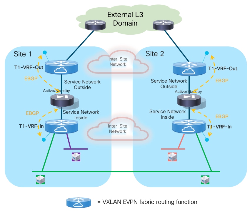
The Service Network Inside and Service Network Outside are two fabrics’ VXLAN segment implementing the anycast gateway functionality to establish Layer 3 connectivity between the firewall and the fabric. Because the EBGP adjacencies should only be established inside the same fabric for both the inside and outside VRFs, there is no need to extend those VXLAN segments across sites. This allows you to operate the fabrics more independently, while still being able to leverage the communication path via the intersite network in case of failure of the local connectivity toward the external Layer 3 domain (under the assumption that the Inter-Site network and the external Layer 3 domain are two separate infrastructures).
As for the tenant’s networks, it is possible to deploy a mix of stretched and not stretched subnets. Intra-tenant Layer 3 connectivity is always optimized by leveraging the VXLAN EVPN distributed anycast gateway functionality provided by the leaf nodes. The connectivity extension functionalities of VXLAN Multi-Site are leveraged to seamlessly extend intra-VRF Layer 2 and Layer 3 connectivity also across fabrics.
Both the tenant’s inside and outside VRFs should be extended across sites using Multi-Site. Doing so for the inside VRF enables East-West Layer 2 and Layer 3 connectivity inside the tenant’s security zone (all those communication flows are established “behind” the firewall). The stretching of the outside VRF ensures instead that the intersite VXLAN data-path can be utilized to steer inbound traffic to the “right firewall” (i.e. the firewall in the site where the destination endpoint is connected). This may be required when enabling host-routes advertisement for stretched subnets or for establishing inter-tenant communication flows (both those scenarios are going to be discussed later in this section).
The firewall service is front ending the entire tenant’s security zone; this implies that any traffic flow sent to a destination outside the tenant’s address space should be forced to go through the firewall device. This design principle allows you to drastically simplify the exchange of reachability information, as only a default route (0.0.0.0/0) can be originated in each site from the outside VRF toward the local firewall. The firewall then propagates that information in the tenant’s inside VRF routing domain (Figure 46).
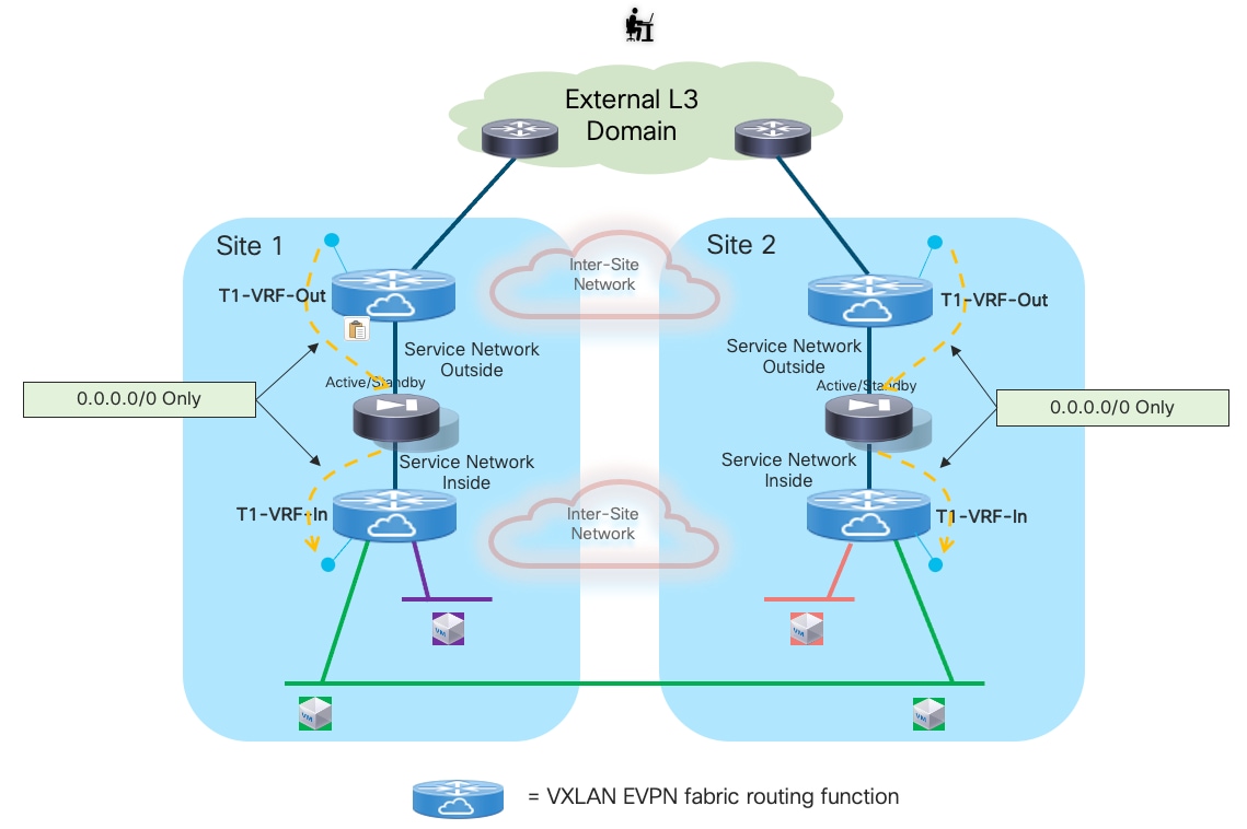
The deployment of independent firewall services in each fabric, while allowing you to simplify the configuration and removing the need to extend networks (keepalive link, inside and outside service networks) across sites, brings up the critical requirement to avoid the creation of asymmetric traffic path via firewalls in different sites for both North-South and East-West (inter-tenant) communication. This is because there is no state synchronization happening across sites between the firewall devices, nor any clustering mechanism allowing to redirect traffic.
Figure 47 highlights how the announcement of the same IP prefix into the external network for IP subnets that are stretched across sites may cause the creation of asymmetric traffic, as the outbound flows by default are steered through the local firewall service, whereas inbound flows are load-balanced across the two sites. As a result, stateful traffic is dropped as shown in the figure below.
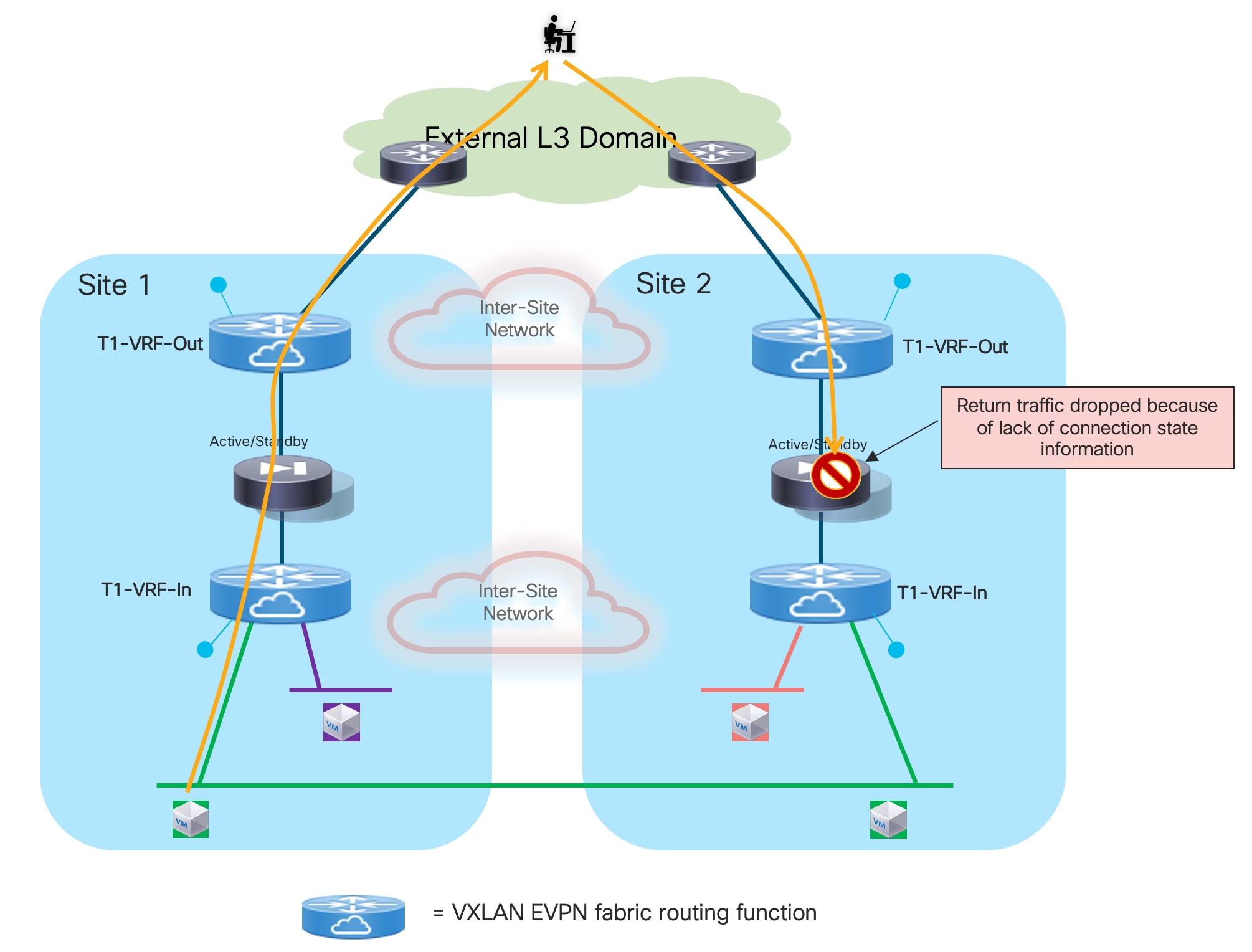
A typical solution to this problem is to enable host-route advertisement for all the endpoints which belong to network segments that are stretched across sites. Combined with the fact thatoutbound flows should always prefer the use of the local path to communicate with the external network domain, the advertisement of host route information ensures that both legs of each traffic flow traverse the same firewall device.
Note: The advertisements of host-routes information should be enabled only for stretched subnets. Also, proper filtering should be in place to ensure that in each site only the host-routes of the devices locally discovered in that site are announced and not also the ones received via EVPN from the remote BGW devices for the remote endpoints part of the same subnet. This filtering action is optional when using BGP for peering with the external network domain, as the BGP AS-Path for remote host-routes would be longer (because it also includes the BGP ASN of the remote site). The filtering is instead required when using a different routing protocol between the border leaf nodes and the external routers.
Figure 48 shows this behavior for intra-VRF North-South communication, in the scenario where host-routes can be advertised toward the external Layer 3 domain.
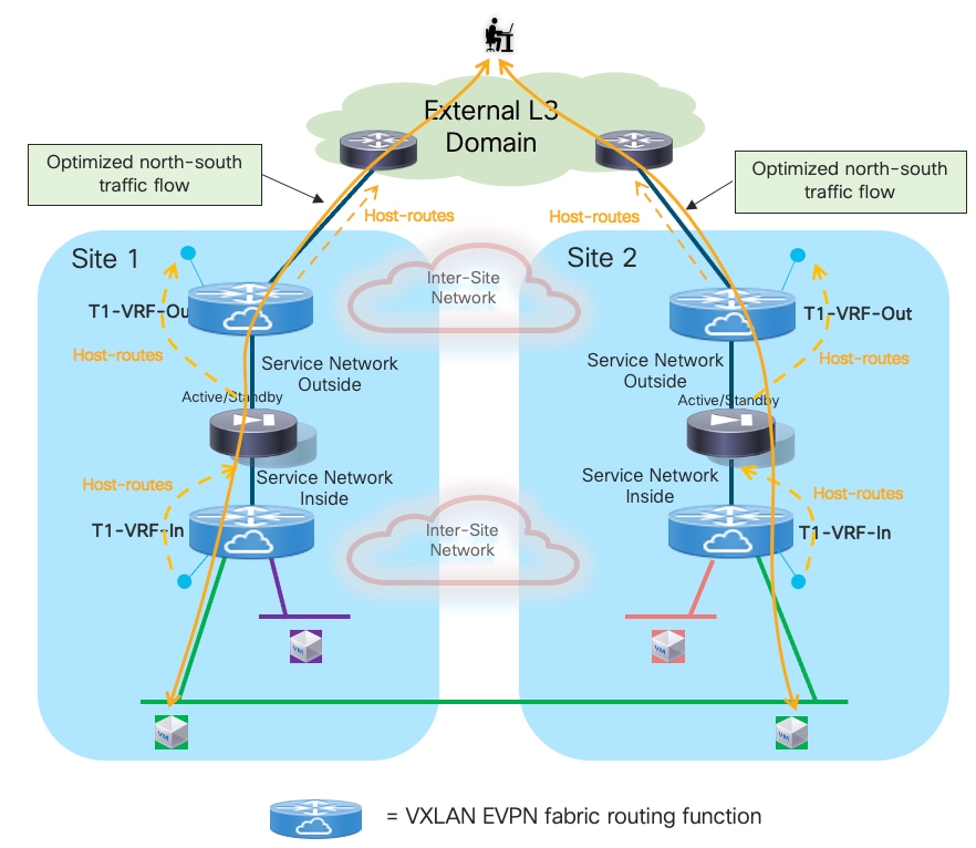
In deployments where it is not possible to advertise host-routes toward the external Layer 3 domain (either for scalability reasons or because that connectivity is offered by a Service Provider not accepting the injection of host-routes in their backbone), the stretching of the outer VRF via Multi-Site becomes key to ensure that the same firewall is used for both legs of the same North-South traffic flow.
As shown in Figure 49 below, even when the inbound traffic originated from the external network is steered to the “wrong” data center, the granular routing information in the outside VRF would ensure that traffic can be forwarded between Border Gateway devices and sent to the “right” site before crossing the firewall device. This results in an inbound suboptimal path but ensures that both the inbound and outbound legs of each specific traffic flow always traverse the same firewall node, preventing the dropping of traffic shown in previous Figure 47.
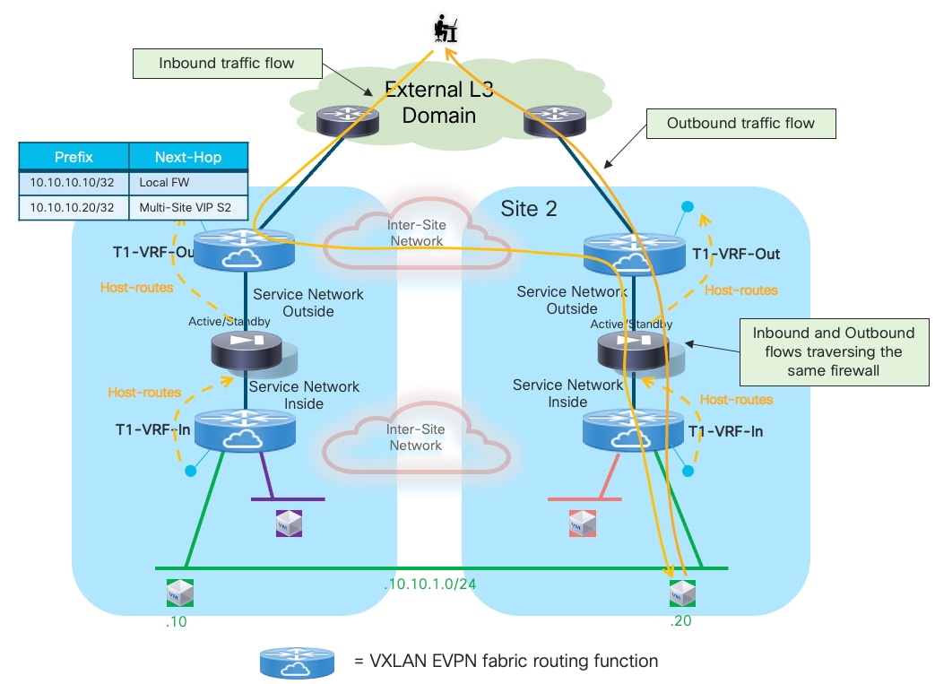
Note: In the scenario where an endpoint belonging to the stretched networks performs live migration across fabrics, the traffic flows sourced from and destined to the moved endpoint are sent toward the local firewall node front-ending the endpoint’s VRF routing domain. Therefore, after the migration is completed, all stateful communications must be re-established.
A firewall failover is always a local event in each site; functionality like Graceful Restart can be leveraged on the network devices and on the firewall to minimize the entity of traffic outage during the failover event. The convergence time for the traffic flows is also influenced by the time it takes for the standby firewall to detect the failure of the peer device and take over the active role, so it can start forwarding traffic. Given the fact that both active and standby units are locally deployed, it is possible to set the keepalives and hold-time timers more aggressively to speed up this failure detection.
In the dual-failure corner case scenario where both firewall nodes in a fabric experience an outage, connectivity to destinations outside of a specific tenant’s security zone could still be established via the remote site, given that the external prefixes for a given tenant are learned via EVPN from the remote BGW nodes (Figure 50).
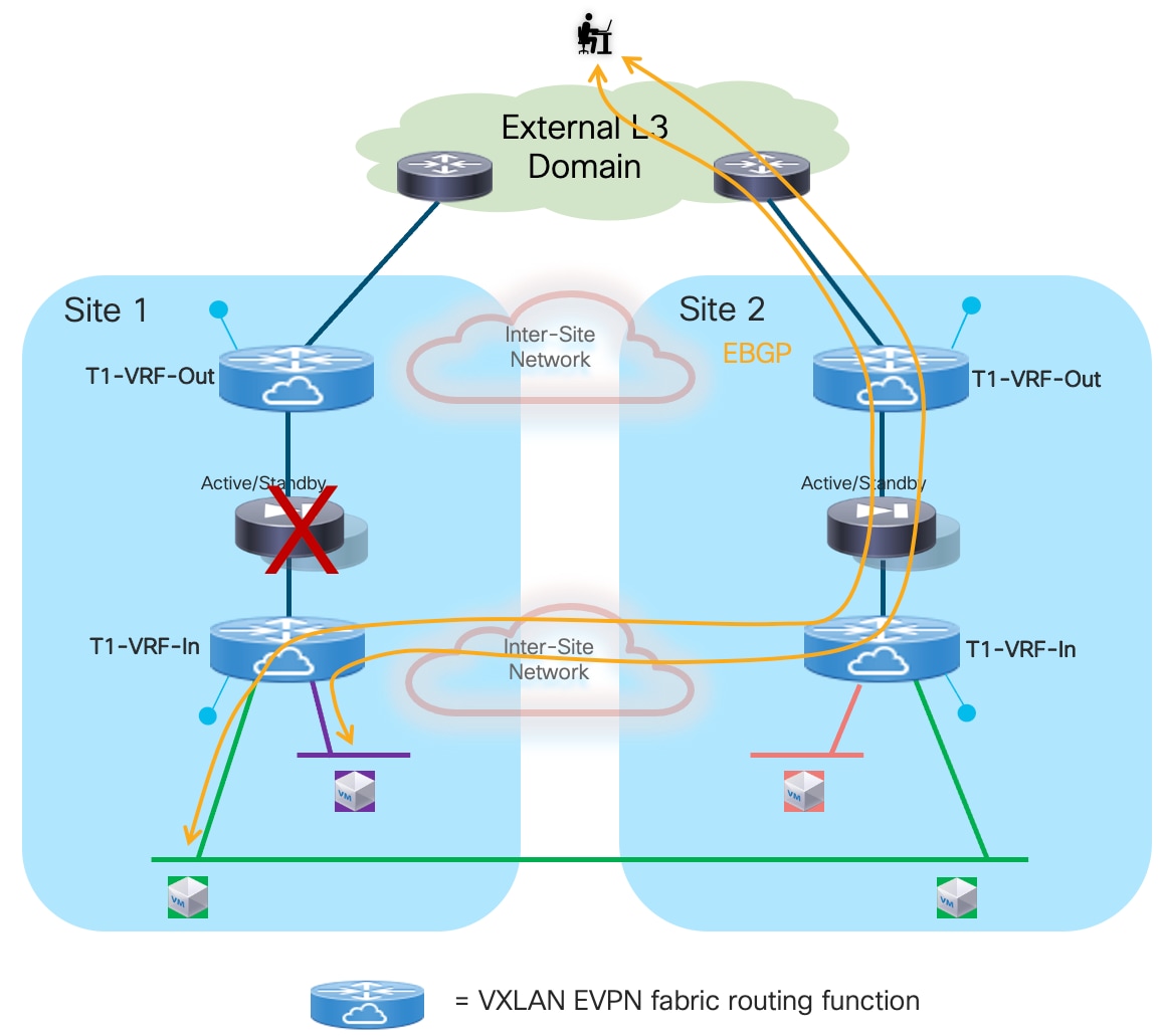
To speed up the convergence and start using that alternate path shown in figure above, it is critical to ensure that the local EBGP sessions are brought down as soon as the local firewalls fail, without waiting for the slow BGP hold-time timer to expire (default value is 180 seconds). The use of Bidirectional Forwarding Detection (BFD) is recommended to achieve that goal because BFD sessions are established between the loopback interfaces part of the inside and outside VRFs and the inside/outside firewall interfaces. Even with default BFD timers, the BFD sessions are brought down in less than a second and that causes also the BGP adjacencies established with the failed firewall to go down.
As previously mentioned, a best practice recommendation is to apply a filter on the BGP session between the internal VRF and the firewall to announce only the host-routes for the local endpoints belonging to stretched subnets (and not the ones of remote endpoints learned via EVPN). For the sake of completeness and to ensure all traffic flows can be recovered in a dual firewall failure scenario, the following specific prefixes should be announced from the internal VRF toward the local firewall node:
● Stretched subnets: subnet prefix and host-routes for local endpoints.
● Local subnets: subnet prefix only.
● Remote subnets (information received via EVPN): subnet prefix but with a worst metric (for example, using AS-Path prepend).
This recommendation is driven by the requirements that, at steady state, connectivity toward a site-local subnet should always traverse the local firewall in that site. As shown in Figure 51, this should normally be the case, because the 10.10.2.0/24 prefix advertised from the border leaf nodes in Site 1 toward the external network should always have a better metric (shorter AS-Path) than the prefix advertised from the border leaf nodes in Site 2.
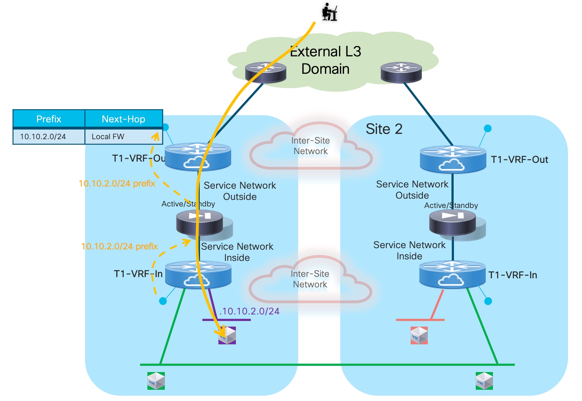
If however, inbound traffic destined to 10.10.2.0/24 was received on the border leaf nodes in Site 2 (in the outside VRF routing domain), the design must always guarantee that routing information on all the devices in that fabric can steer the traffic toward the BGWs in Site 1. This ensures that both legs of the communication are sent through the same FW service deployed in Site 1 (Figure 52).
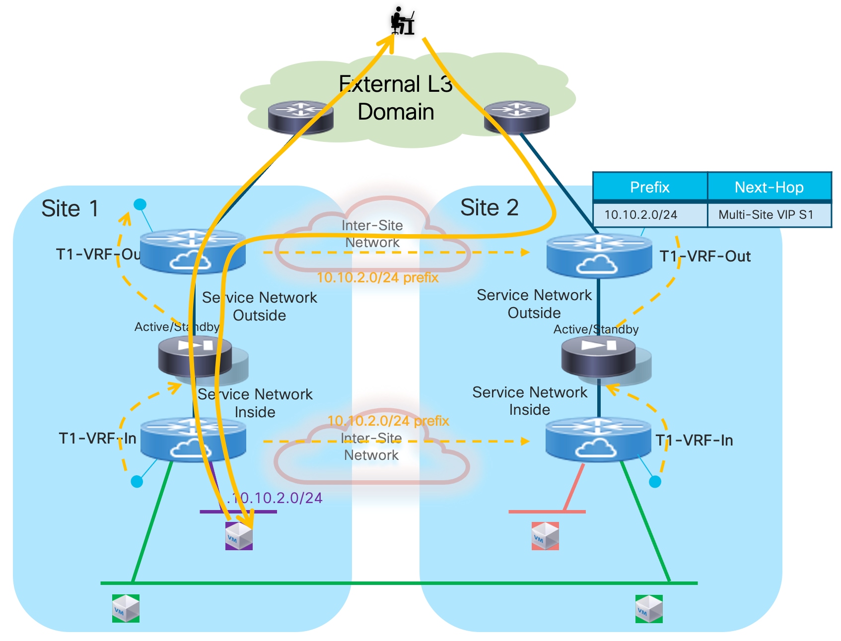
In the specific design discussed here, the behavior exhibited above may not happen by default. To better understand this, consider the scenario in Figure 53, where different devices are used in Site 2 for the roles of border leaf, service leaf, and BGW nodes.
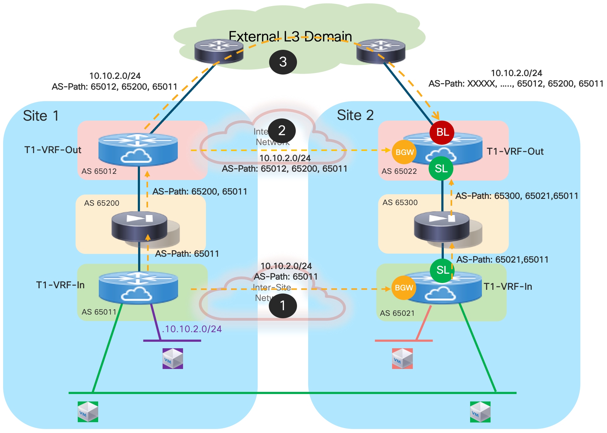
The 10.10.2.0/24 route can be learned in the context of the outside VRF (T1-VRF-Out) in Site 2 via three different paths:
● In the inside VRF (T1-VRF-In), from the BGWs in Site 1 is advertised to the BGWs in Site 2 and propagated inside fabric 2. The prefix is then received by the service leaf nodes and sent to the local firewall. The local firewall sends it back to the service leaf nodes where it is received in the context of the outside VRF and propagated inside the fabric. As a result, the AS-Path contains the (65300, 65021, 65011) sequence.
● In the outside VRF, from the BGWs in Site 1 is advertised to the BGWs in Site 2 and propagated inside fabric 2. Because the prefix is originated from the service leaf in Site 1 and propagated via the local firewall, the AS-Path has the same length of the point above and contains the sequence (65012, 65200, 65011).
● Unless filtered, the prefix is also received on the border leaf nodes in Site 2 from the external network domain and propagated inside the fabric in the outside VRF. The AS-Path in this case also contains all the ASNs (at least an additional one) that have been traversed in the external network, so contains the sequence (XXXXX, …, 65012, 65200, 65011).
Based on the information above, let’s now consider what would be the best path to reach the prefix 10.10.2.0/24 on the different fabric nodes in Site 2 (Figure 54):
● BL nodes: the prefix is learned as a “type internal” route (i.e. from the fabric EVPN control plane) from the BGW nodes and the SL nodes. Because the AS-Path has the same length, those two paths will be considered equal cost. The prefix is also learned as a “type external” route from the external network, but with a longer AS-Path, so this would be a worst path when compared with the previous two.
● BGW nodes: the prefix is learned as a “type external” route from the BGWs in Site 1 and as a “type internal” route from the BL nodes and the SL nodes. The AS-Path of the prefix learned from the BGWs in Site 1 and from the SL nodes has the same length, hence the path via the remote BGWs is always preferred being of “type external”.
● SL nodes: the prefix is learned as “type external” from the local firewall and as “type internal” from the local BGW nodes and from the local BL nodes. The AS-Path of the prefix learned from the local BGW nodes and from the local firewall has the same length, hence the path via the local firewall is always preferred being of “type external”.
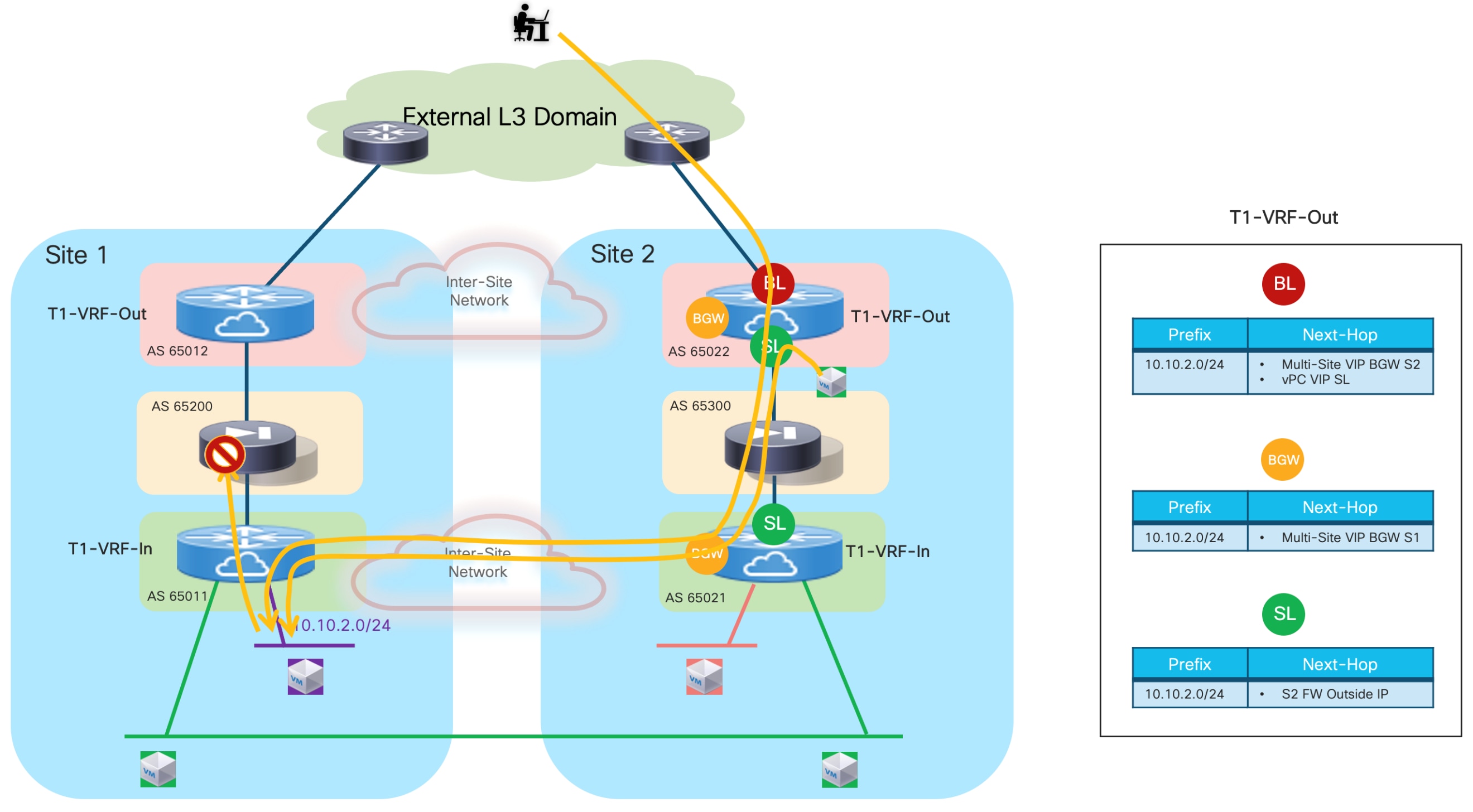
As highlighted in the figure above, traffic flows destined to the 10.10.2.0/24 may end up traversing the local firewall in Site 2, violating the design principle previously described in Figure 52 and causing the creation of asymmetric traffic path that would not allow to successfully establish communication. This is the case for flows originated from endpoints directly connected to the service leaf nodes (from the green VM in SIte2 shown in figure above) and half of the inbound flows received on the border leaf nodes from the external network.
Both the issues described above can be solved with the use of AS-Path prepend on the service leaf in Site 2 when advertising to the local firewall Site 1’s local subnet (received in the inside VRF), as shown in Figure 55 below.
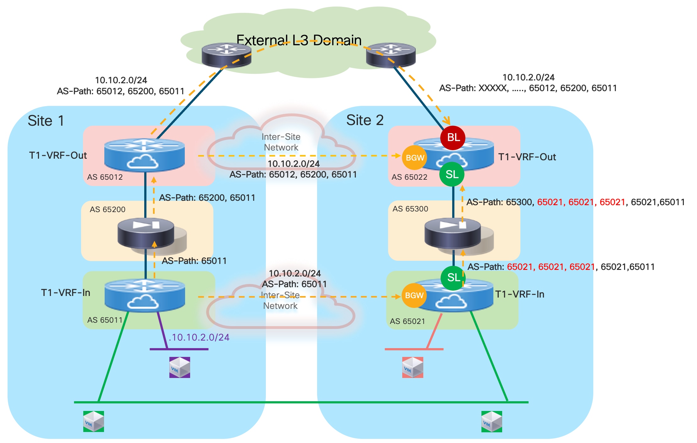
Note: The example above shows the prepend of AS 65021 for 3 times. The right value to use depends on the specific deployment scenario under considerations but should always be chosen to ensure that the path via the local firewall in Site 2 is used only as last resort when the other two paths (via the BGW nodes or via the BL nodes) have failed.
Figure 56 shows how the new reachability information learned on the nodes in Site 2 removes the creation of the asymmetric traffic path shown in previous Figure 54.
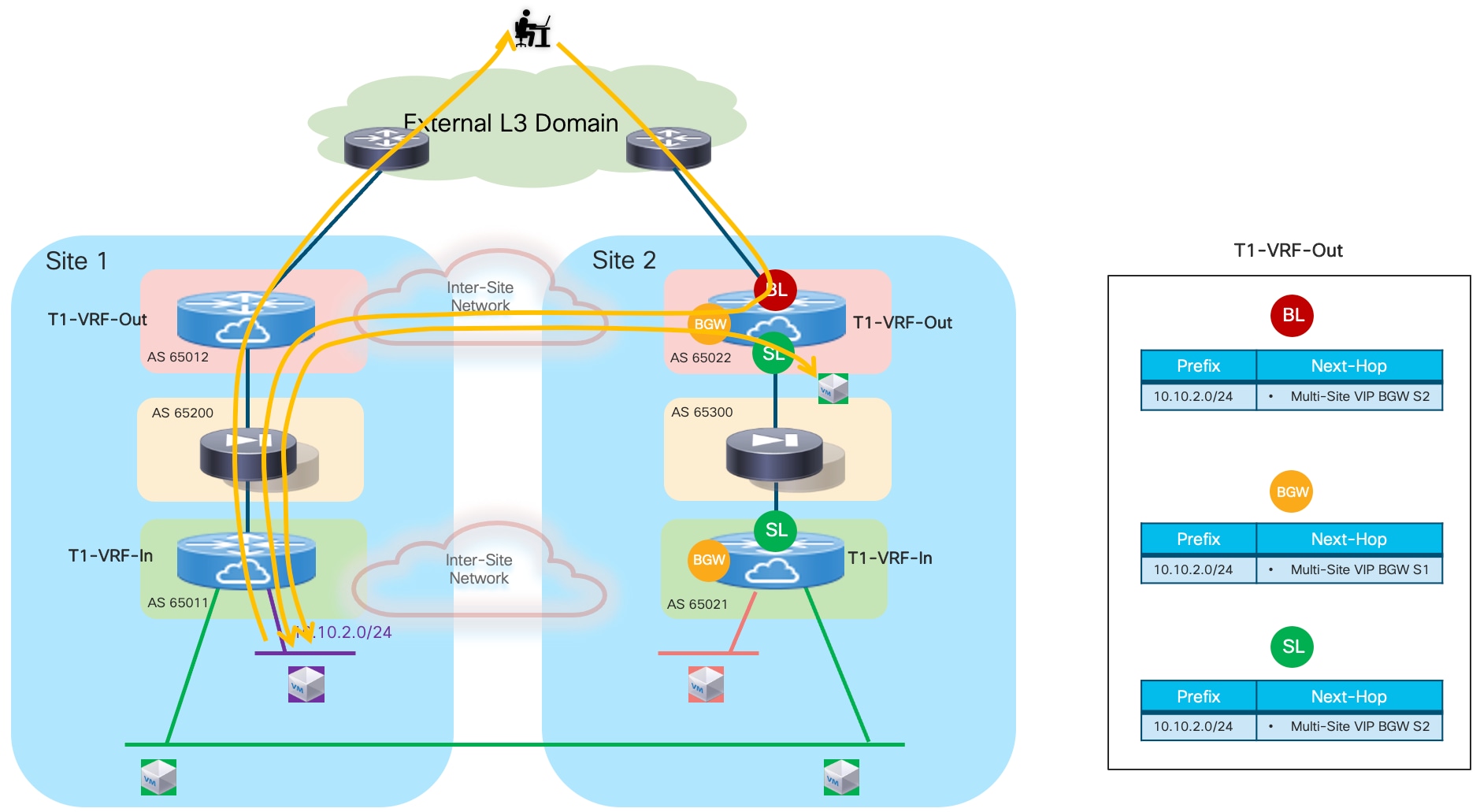
The application of the routing tuning previously described also ensures the recovery of traffic flow in the specific scenario here the firewall service in a site completely fails but inbound traffic flows are still steered to the site that experienced the total firewall outage (Figure 57).
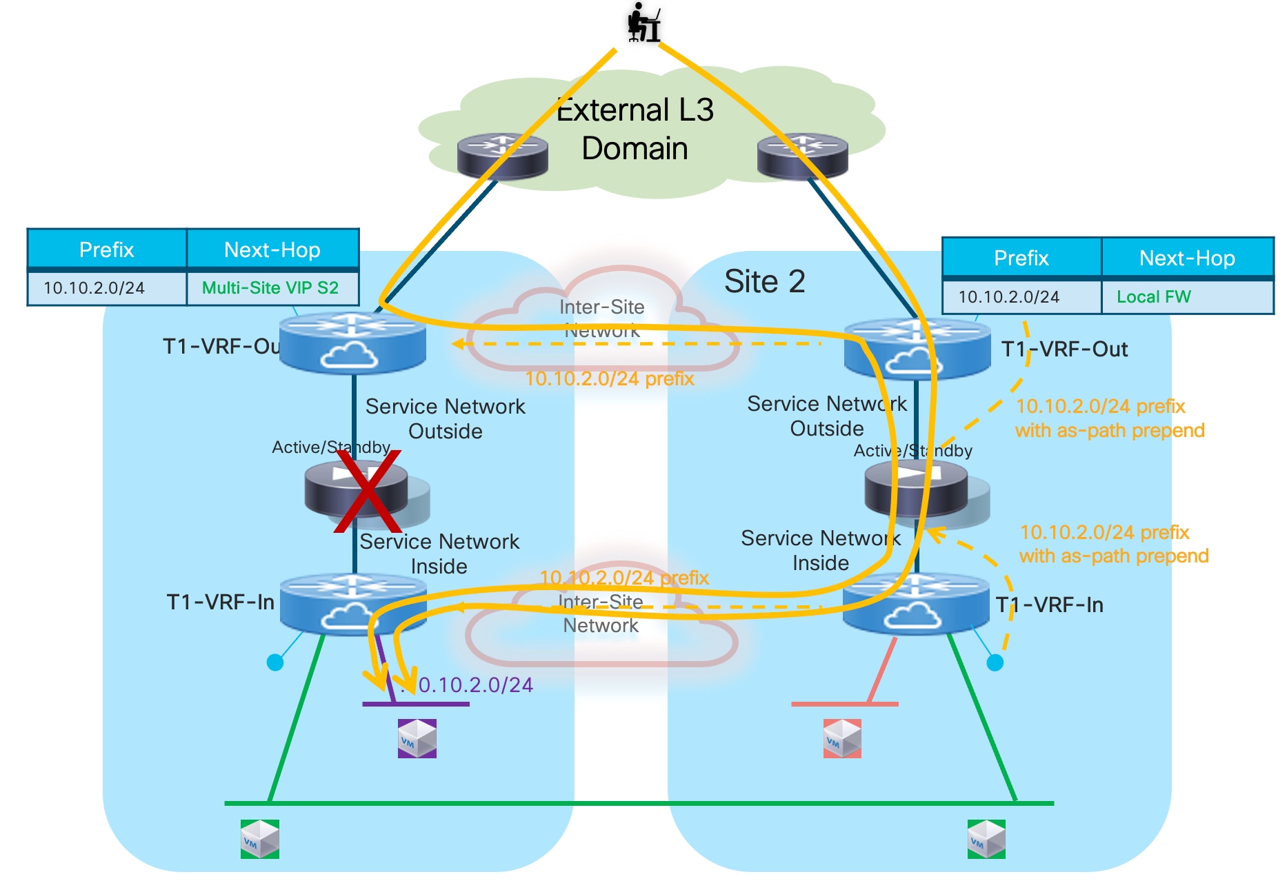
While the deployment considerations above apply to a single tenant deployment, Figure 58 highlights a multi-tenant (multi-VRF) deployment, where each tenant’s security zone is front ended by a dedicated firewall service (physical or logical). Inter-tenant communication is possible via a common Shared-VRF-Out routing domain. The main design principle for this deployment model is that all intra-site and inter-site traffic flows between endpoints belonging to different tenants should always traverse (for both directions) the firewalls associated to each tenant/VRF deployed in the same site where the endpoints are located. This ensures that the traffic is always kept symmetrical to avoid traffic drops for stateful communication.
Note: An alternative deployment model consists in having a single FW shared by the different tenants (each tenant would hence use a dedicated interface). In that case, the firewall itself would perform the “fusion routing” function to allow/deny inter-tenant communication and connectivity between each tenant and the external network domain. The drawback of that approach, and the reason why is not recommended in this paper, is that the security policy provisioning for all the tenants must be done on the same firewall device and this may not be desirable (from a RBAC point of view) and may lead to provisioning mistakes affecting multiple tenants at once.
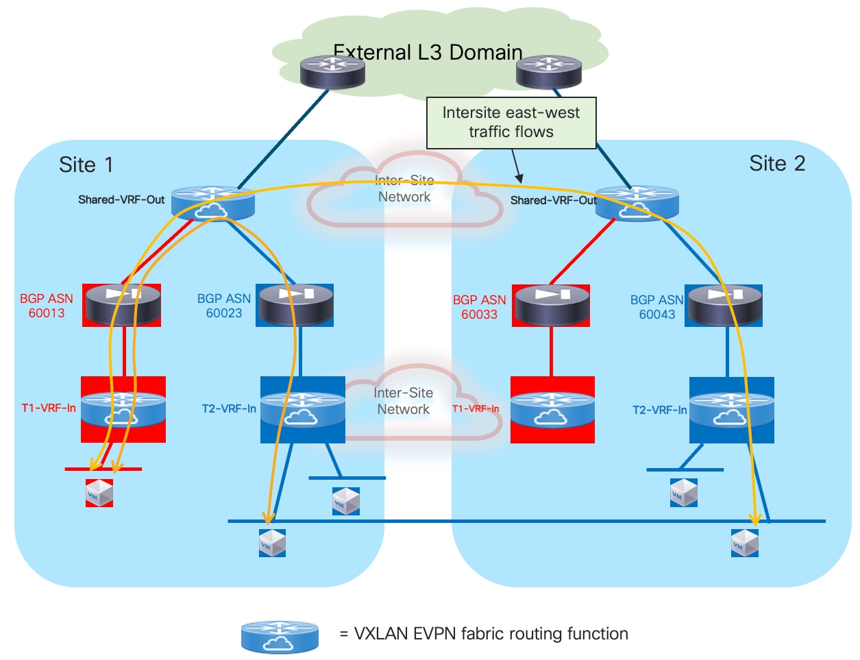
The enablement of the traffic forwarding behavior shown in figure above is achieved automatically when following the best practice recommendation previously mentioned for a single tenant scenario. The only additional consideration is the deployment of the shared northbound fusion VRF that enables the inter-tenant communication and the connectivity between all the tenants and the common external Layer 3 domain. As it was the case for the outside tenant VRF, the best practice recommendation is to stretch the outside fusion VRF via Multi-Site, so that all the intersite inter-tenant communication can be achieved through VXLAN encapsulation performed by the BGW nodes.
Also, it is recommended that each tenant’s firewall is part of its unique BGP ASN to ensure inter-tenant prefixes can be exchanged by default via the shared external VRF.
Note: If the firewalls dedicated to each tenant are logical context defined for the same physical firewall, this may require a “local-as” configuration on each firewall context. This is for example the case with Cisco ASA/FTD firewalls, because all the logical contexts inherit the same global BGP ASN defined as part of the “System context”.
Figure 59 highlights the information contained in the routing table of the Shared external VRF that enables the inter-tenant communication. As mentioned, this is the result of the application of all the best practices previously discussed for the single tenant scenario.
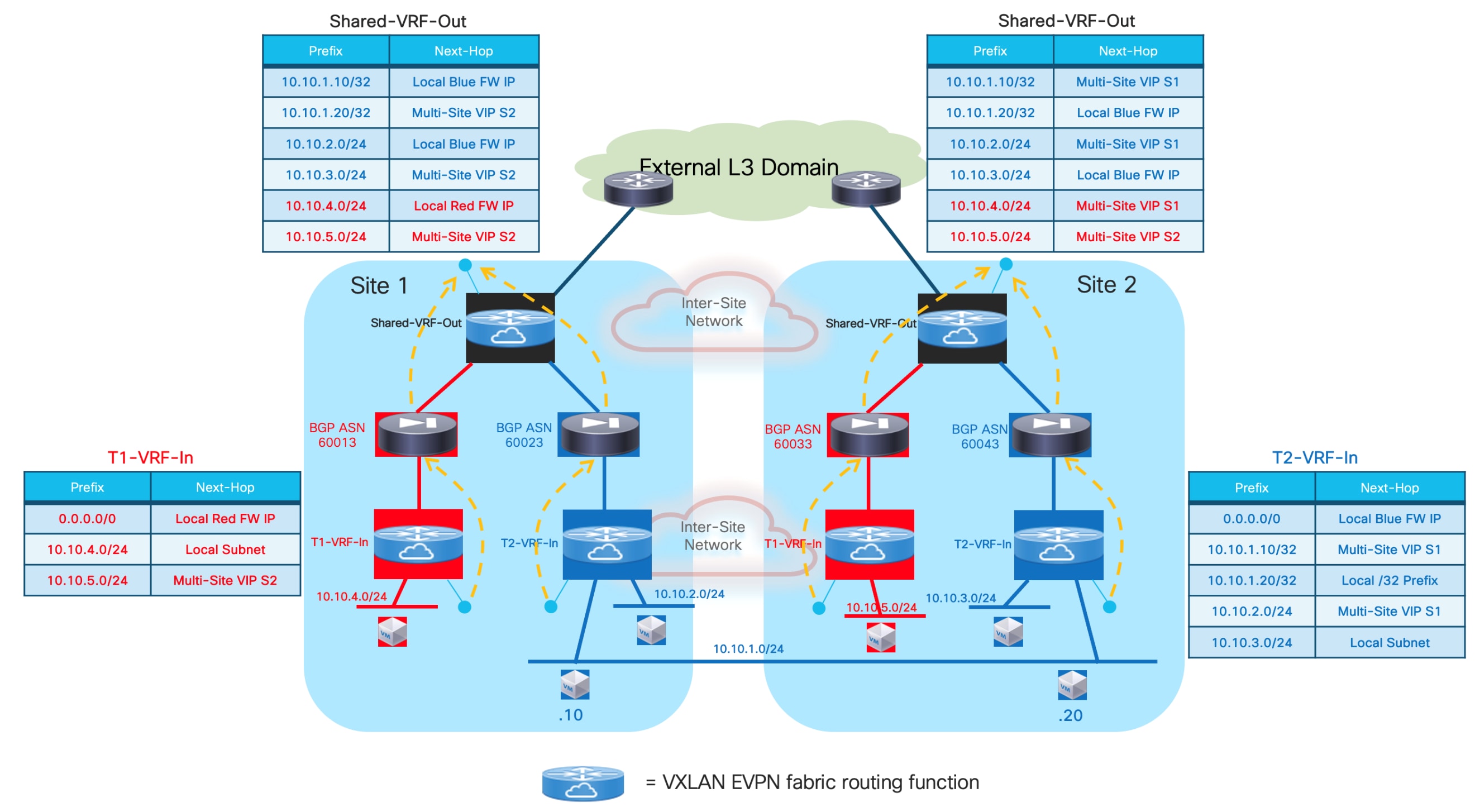
The figure above also shows the forwarding tables for the inside VRF of each tenant containing info on how to establish Layer 2 and Layer 3 communication in the context of the same security zone (VRF), both intra-site and inter-site. Additionally, a default-route would be propagated down from the outside Shared VRF (through the firewall service dedicated to each tenant) to steer northbound all the flows destined to resources external to the tenant’s security zone. The example in Figure 59 shows the content of the routing tables only for the Red VRF in Site 1 and the Blue VRF in Site 2 to avoid overcrowding the diagram.
Configuration Samples
The samples below show the required configuration on the fabric leaf nodes and on the firewall to implement the design shown in the reference topology in Figure 60.
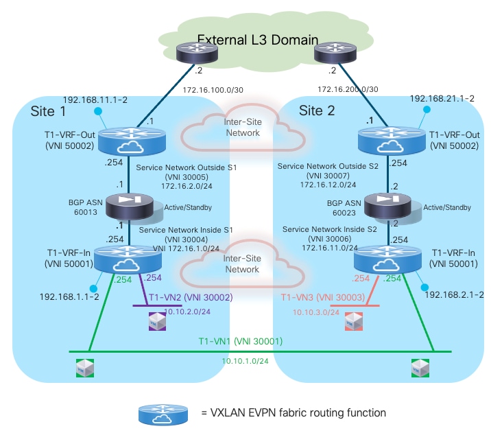
Compute Leaf Nodes
Define the inside VRF for a specific tenant and the L2VNI segments (inclusive of SVIs implementing the anycast default gateway function) representing the subnets where the endpoints are connected.
vlan 2001
vn-segment 50001
!
vlan 2301
vn-segment 30001
!
vlan 2302
vn-segment 30002
!
vrf context t1-vrf-in
vni 50001
rd auto
address-family ipv4 unicast
route-target both auto
route-target both auto evpn
address-family ipv6 unicast
route-target both auto
route-target both auto evpn
!
interface Vlan2001
no shutdown
mtu 9216
vrf member t1-vrf-in
no ip redirects
ip forward
ipv6 address use-link-local-only
no ipv6 redirects
!
interface Vlan2301
no shutdown
vrf member t1-vrf-in
ip address 10.10.1.254/24 tag 12345
fabric forwarding mode anycast-gateway
!
interface Vlan2302
no shutdown
vrf member t1-vrf-in
ip address 10.10.2.254/24 tag 12345
fabric forwarding mode anycast-gateway
!
interface nve1
member vni 30001
mcast-group 239.1.1.1
member vni 30002
mcast-group 239.1.1.1
member vni 50001 associate-vrf
!
route-map fabric-rmap-redist-subnet permit 10
match tag 12345
!
router bgp 65001
vrf t1-vrf-in
address-family ipv4 unicast
advertise l2vpn evpn
redistribute direct route-map fabric-rmap-redist-subnet
maximum-paths 4
address-family ipv6 unicast
advertise l2vpn evpn
redistribute direct route-map fabric-rmap-redist-subnet
maximum-paths 4
evpn
vni 30001 l2
rd auto
route-target import auto
route-target export auto
vni 30002 l2
rd auto
route-target import auto
route-target export auto
!
interface port-channel1
description vPC to the ESXi host
switchport mode trunk
switchport trunk allowed vlan 2301-2302
spanning-tree port type edge trunk
spanning-tree bpduguard enable
mtu 9216
vpc 1
Service Leaf Nodes
Define the VRFs inside and outside for a specific tenant and their associated minimal required configuration (including the loopback interfaces for EBGP peering). As previously mentioned, depending on the specific use case, the outside VRF could be dedicated per tenant/VRF or shared between all the tenants/VRFs. The configuration below applies to one of the service leaf nodes deployed in Site1, similar configuration is required for the other service leaf nodes.
vlan 2001
vn-segment 50001
vlan 2002
vn-segment 50002
vrf context t1-vrf-in
vni 50001
rd auto
address-family ipv4 unicast
route-target both auto
route-target both auto evpn
address-family ipv6 unicast
route-target both auto
route-target both auto evpn
vrf context t1-vrf-out
vni 50002
rd auto
address-family ipv4 unicast
route-target both auto
route-target both auto evpn
address-family ipv6 unicast
route-target both auto
route-target both auto evpn
interface Vlan2001
vrf member t1-vrf-in
ip forward
ipv6 address use-link-local-only
no ip redirects
no ipv6 redirects
mtu 9216
no shutdown
interface Vlan2002
vrf member t1-vrf-out
ip forward
ipv6 address use-link-local-only
no ip redirects
no ipv6 redirects
mtu 9216
no shutdown
interface loopback2
vrf member t1-vrf-in
ip address 192.168.1.1/32 tag 12345
interface loopback3
vrf member t1-vrf-out
ip address 192.168.11.1/32 tag 12345
interface nve1
member vni 50001 associate-vrf
member vni 50002 associate-vrf
Define the L2VNI segments used as Service Networks (Inside and Outside). Different local L2VNIs are defined for each fabric.
vlan 401
vn-segment 30004
vlan 402
vn-segment 30005
interface Vlan401
vrf member t1-vrf-in
no ip redirects
no ipv6 redirects
ip address 172.16.1.254/24 tag 12345
fabric forwarding mode anycast-gateway
no shutdown
interface Vlan402
vrf member t1-vrf-out
no ip redirects
no ipv6 redirects
ip address 172.16.2.254/24 tag 12345
fabric forwarding mode anycast-gateway
no shutdown
interface nve1
member vni 3004
mcast-group 239.1.1.4
member vni 3005
mcast-group 239.1.1.5
!
evpn
vni 30004 l2
rd auto
route-target import auto
route-target export auto
vni 30005 l2
rd auto
route-target import auto
route-target export auto
Create the EBGP peerings between the loopback interfaces of the local service leaf nodes (part of the inside and outside VRFs) and the firewall node. As previously described, there are several important best practice configurations to be applied:
● “local-as” (with the “no-prepend” and “replace-as” options) must be used for adjacencies with the firewall established from both the inside and outside VRFs so that the firewall node is able to propagate routing advertisement between them (by default it would not be allowed to advertise prefixes toward the same BGP ASN from where they were received). The result of this configuration in NX-OS is the advertisement to the firewall node of prefixes from each VRF toward carrying only the specified “local-as” value.
● BFD multi-hop sessions should be created between the loopbacks part of the inside and outside VRFs and the firewall node. This is needed to speed up convergence in the corner case scenario where both firewall nodes in a site fail. The EBGP sessions established with the local firewall nodes are brought down immediately and all the communication from the networks part of the inside VRF and the external resources are re-established through the firewall service active in the remote site.
● Enabling maximum-path and export-gateway-ip. The latter command is to ensure that in both the internal and external VRFs, traffic originated from any leaf node and destined northbound (or southbound) is only optimally encapsulated to the service leaf nodes connected to the active firewall node. This is required when the active and standby firewall nodes are connected to different service leaf node pairs inside the same fabric.
● Specific route-maps should be applied on the EBGP peerings established between the tenant’s internal and external VRFs with the local firewall node.
On the peering between the external VRF and the firewall’s outside interface, the outbound route-map “default-route-only” ensures that only a default route is advertised from the external VRF to the local firewall to be injected into the internal VRF. This is because all the traffic leaving the specific tenant’s security zone should always be steered toward the local firewall node.
On the peering between the internal VRF and the firewall’s inside interface, the outbound route-map “prefixes-to-FW-context” is applied for different reasons:
◦ Deny the advertisement of host routes for remote endpoints part of stretched subnets.
◦ Advertise prefixes for remote non-stretched subnets with a worst metric (in this example longer AS-Path).
◦ Deny the advertisement of host routes for local endpoints part of non-stretched subnets.
The sample below show the complete configuration required in this case. The “redistribute hmm” command is required to advertise host routes for the endpoints that are directly connected to the service leaf nodes (when the service leaf nodes have also the role of compute leaf nodes).
Note: It is best practice recommendation to enable “advertise-pip” under the L2VPN EVPN BGP address-family to ensure successful establishment of EBGP adjacencies between the firewall and the service leaf nodes in both the internal and external VRFs. Refer to previous Figure 28 for more information.
Feature bfd
!
ip prefix-list default-route seq 5 permit 0.0.0.0/0
!
ip prefix-list host-routes seq 5 permit 0.0.0.0/0 eq 32
!
ip prefix-list local-host-routes-non-stretched-subnets seq 5 permit 10.10.2.0/24 eq 32
!
ip AS-Path access-list remote-asn seq 5 permit “_65002_”
!
route-map fabric-rmap-redist-subnet permit 10
match tag 12345
!
route-map default-route-only permit 10
match ip address prefix-list default-route
!
route-map prefixes-to-FW-context deny 5
match AS-Path remote-asn
match ip address prefix-list host-routes
route-map prefixes-to-FW-context permit 10
match AS-Path remote-asn
set AS-Path prepend 65011 65011 65011 65011 65011 65011
route-map prefixes-to-FW-context deny 15
match ip address prefix-list local-host-routes-non-stretched-subnets
route-map prefixes-to-FW-context permit 20
!
route-map any permit 10
!
router bgp 65001
router-id 10.12.0.2
address-family l2vpn evpn
advertise-pip
vrf t1-vrf-in
address-family ipv4 unicast
advertise l2vpn evpn
redistribute direct route-map fabric-rmap-redist-subnet
redistribute hmm route-map any
maximum-paths 4
export-gateway-ip
neighbor 172.16.1.1
local-as 65011 no-prepend replace-as
bfd multihop
remote-as 65200
update-source loopback2
ebgp-multihop 10
address-family ipv4 unicast
route-map prefixes-to-FW-context out
vrf t1-vrf-out
address-family ipv4 unicast
advertise l2vpn evpn
redistribute direct route-map fabric-rmap-redist-subnet
maximum-paths 4
export-gateway-ip
neighbor 172.16.2.1
local-as 65012 no-prepend replace-as
bfd multihop
remote-as 65200
update-source loopback3
ebgp-multihop 10
address-family ipv4 unicast
route-map default-route-only out
default-originate
!
interface nve1
advertise virtual-rmac
Border Gateway/Border Leaf Nodes
The BGWs are used to control the extension of Layer 2 and Layer 3 connectivity across sites based on the L2VNIs and L3VNIs that are locally configured on the BGW nodes. Based on the reference topology shown in Figure 60, the L2VNI 30001 (associated to the stretched subnet) and the L3VNIs 50001 and 50002 (associated to the internal and external VRFs) must be locally defined on the BGWs. The configuration below applies to one of the BGW nodes deployed in Site1, similar configuration is required for the other BGW nodes.
Note: It is best practice recommendation also to enable “advertise-pip” under the L2VPN EVPN BGP address-family on the BGW nodes to avoid data-plane forwarding issues across fabrics or to local leaf nodes where only Layer 3 communication is expected (i.e. there are no L2VNIs extended).
vlan 301
vn-segment 300301
!
vlan 2001
vn-segment 50001
!
vlan 2002
vn-segment 50002
!
vrf context t1-vrf-in
vni 50001
rd auto
address-family ipv4 unicast
route-target both auto
route-target both auto evpn
address-family ipv6 unicast
route-target both auto
route-target both auto evpn
vrf context t1-vrf-out
vni 50002
rd auto
address-family ipv4 unicast
route-target both auto
route-target both auto evpn
address-family ipv6 unicast
route-target both auto
route-target both auto evpn
!
interface Vlan2001
no shutdown
mtu 9216
vrf member t1-vrf-in
no ip redirects
ip forward
ipv6 address use-link-local-only
no ipv6 redirects
interface Vlan2002
no shutdown
mtu 9216
vrf member t1-vrf-out
no ip redirects
ip forward
ipv6 address use-link-local-only
no ipv6 redirects
!
interface nve1
advertise virtual-rmac
member vni 50001 associate-vrf
member vni 50002 associate-vrf
member vni 30001
multisite ingress-replication
mcast-group 239.1.1.1
!
router bgp 65001
router-id 10.12.0.4
address-family l2vpn evpn
advertise-pip
!
evpn
vni 30001 l2
rd auto
route-target import auto
route-target export auto
If the BGWs are also used as border nodes to connect to the external routed domain, it is required to establish EBGP VRF-Lite adjacencies with the WAN edge routers.
interface Ethernet1/2.2
mtu 9216
encapsulation dot1q 2
vrf member t1-vrf-out
ip address 10.33.0.1/30
no shutdown
!
router bgp 65001
vrf t1-vrf-in
address-family ipv4 unicast
advertise l2vpn evpn
redistribute direct route-map fabric-rmap-redist-subnet
maximum-paths 4
vrf t1-vrf-out
address-family ipv4 unicast
advertise l2vpn evpn
redistribute direct route-map fabric-rmap-redist-subnet
maximum-paths 4
neighbor 10.33.0.2
remote-as 65003
address-family ipv4 unicast
send-community
send-community extended
Firewall
The firewall configuration (in this case for a Cisco ASA firewall) is shown below. Notice the required BFD configuration applied to the EBGP neighbors (the loopback interfaces on the external and internal VRFs of the service leaf nodes). In the example below, there is no security policy applied (a “permit any” policy is configured to allow all traffic in/out).
bfd-template multi-hop BFD-MH
interval min-tx 250 min-rx 250 multiplier 3
!
bfd map ipv4 192.168.1.1/32 172.16.1.254/32 BFD-MH
bfd map ipv4 192.168.1.2/32 172.16.1.254/32 BFD-MH
bfd map ipv4 192.168.11.1/32 172.16.2.254/32 BFD-MH
bfd map ipv4 192.168.11.2/32 172.16.2.254/32 BFD-MH
!
interface Port-channel1.401
nameif inside
security-level 0
ip address 172.16.1.1 255.255.255.0 standby 172.16.1.2
!
interface Port-channel1.402
nameif outside
security-level 0
ip address 172.16.2.1 255.255.255.0 standby 172.16.2.2
!
access-list permit-any extended permit ip any any
access-group permit-any in interface outside
!
router bgp 65200
address-family ipv4 unicast
neighbor 192.168.1.1 remote-as 65011
neighbor 192.168.1.1 ebgp-multihop 10
neighbor 192.168.1.1 fall-over bfd multi-hop
neighbor 192.168.1.1 activate
neighbor 192.168.11.1 remote-as 65012
neighbor 192.168.11.1 ebgp-multihop 10
neighbor 192.168.11.1 fall-over bfd multi-hop
neighbor 192.168.11.1 activate
neighbor 192.168.1.2 remote-as 65011
neighbor 192.168.1.2 ebgp-multihop 10
neighbor 192.168.1.2 fall-over bfd multi-hop
neighbor 192.168.1.2 activate
neighbor 192.168.11.2 remote-as 65012
neighbor 192.168.11.2 ebgp-multihop 10
neighbor 192.168.11.2 fall-over bfd multi-hop
neighbor 192.168.11.2 activate
maximum-paths 4
no auto-summary
no synchronization
exit-address-family
!
route inside 192.168.1.1 255.255.255.255 172.16.1.1 1
route inside 192.168.1.2 255.255.255.255 172.16.1.1 1
route outside 192.168.11.1 255.255.255.255 172.16.2.1 1
route outside 192.168.11.2 255.255.255.255 172.16.2.1 1
Redirection to the Firewall Service via ePBR
The approaches discussed in the previous sections of this document, involve stitching traffic to firewall services by leveraging traditional routing-based approaches. While those models work, they represent an inefficient and quite complex way to perform services integration in a modern Data Center multi-fabric architecture. Additionally, once the firewall services are inserted in the data-path, all the traffic must traverse them, making them a potential bottleneck.
A first enhancement to those traditional approaches for intra-VRF traffic inspection is offered by the introduction of Policy Based Routing (PBR), another traditional mechanism that can be used to selectively redirect traffic to the service devices. The challenge with service chaining using PBR is that it requires the user to create unique policies per node and manage the redirection rules manually across all the nodes in the chain. Also, given the stateful nature of the service nodes, the PBR rules must ensure symmetry for the reverse traffic, which adds additional complexity to the configuration and management of the PBR policies.
Cisco NX-OS Enhanced Policy-Based Redirect (ePBR) is a set of functionalities intended to help solve the challenges described above. ePBR provides the capability to selectively redirect and load-balance traffic across a data center network. This includes a data-center design using a VXLAN with BGP EVPN control plane with a distributed anycast gateway, both for single fabric and multi-fabric deployments.
ePBR completely automates the service chaining capability by creating multiple policies and enabling hop-by-hop traffic steering using policy-based redirection policies. These policies enforce traffic redirection by monitoring service-element health and reachability to be able to react to specific firewall’s failure scenarios.
Also, ePBR achieves service chaining without the use of additional headers and thus avoids any increased latency. All of this is achieved at line rate, without any impact to throughput or performance. With the introduction of ePBR, the entire service onboarding, service appliance monitoring using advanced probing mechanisms, service redirection, and load balancing are made flexible and easy to deploy (ePBR can redirect traffic flows to service nodes based on specific Layer 3 and/or Layer 4 filter rules).
Note: While the term ePBR is often going to be used in the context of this document, we can more generically refer to the associated set of functionalities with “service stitching/redirection”.
For specific information on the generic ePBR functionalities, please refer to the paper below:
https://www.cisco.com/c/en/us/products/collateral/switches/nexus-9000-series-switches/layer4-layer7-service-redir-ply-based-redir-wp.html
https://www.cisco.com/c/en/us/td/docs/dcn/nx-os/nexus9000/104x/configuration/epbr/cisco-nexus-9000-series-nx-os-epbr-configuration-guide.html
The following section highlights the use of the ePBR functionalities for service stitching and redirection to the Active/Standby and Active/Active firewall stretched clusters deployment models already introduced in the previous sections of this document. This is covered in the case where the default gateway functionality is offered by the fabric leaf nodes.
ePBR and Active/Standby Firewall Cluster Stretched across Sites
The solutions discussed in the previous sections of this chapter, focused on the use of traditional bridging and routing techniques to integrate an Active/Standby firewall pair in a VXLAN Multi-Site architecture to enforce security for both North-South and East-West communication.
This section presents instead the use of advanced traffic redirection functionalities that allow you to override the regular routing behavior of a VXLAN EVPN fabric to force North-South and East-West traffic flows through firewall devices. As previously mentioned, those advanced traffic redirection functionalities have been bundled under the “enhanced Policy-Based Redirect” (ePBR) umbrella and introduced in NX-OS release 9.3(5).
Before describing the specific ePBR configuration required on the switches to redirect traffic to the firewall for both North-South and East-West communication, it is important to highlight some important design and deployment considerations. Figure 61 below shows the Multi-Site topology for this specific use case.
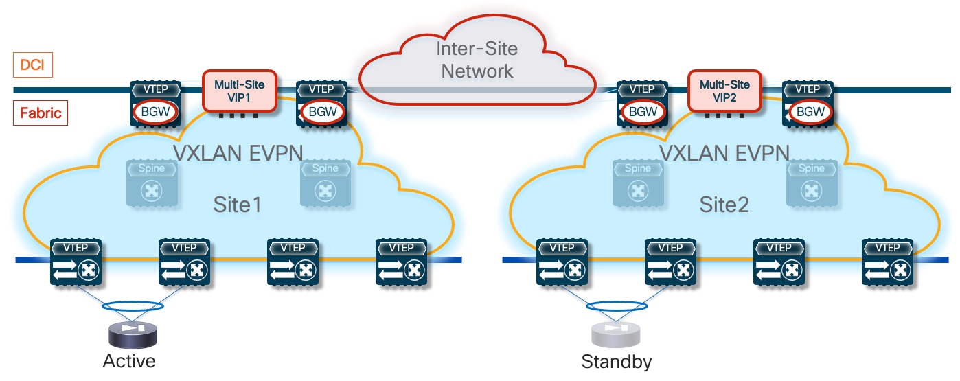
The assumption is that the firewall nodes are deployed as Layer 3 devices connected in one-arm mode to the fabric via a Service Network segment. Because the active and standby firewalls need to share IP addresses part of the same subnet (to facilitate the failover to the standby node when the active fails), the Service Network must be stretched across sites.
Connecting the firewall devices in one-arm mode is the best practice recommendation as it simplifies the routing configuration on the firewall itself. A simple default-route pointing back to the Service Network anycast gateway address defined on the fabric is all that is needed on the firewall. That said, deployment of firewall nodes connected in two-arms mode are also possible and fully supported.
The configuration sample below highlights how to define the firewall service device, an ePBR functionality usually referred to as “service device onboarding”. A single IP address is associated to the defined firewall service representing the active firewall node. This is because the standby node would inherit that same address after a failover event. The same IP address is also defined as “reverse ip” because the firewall is connected in one-arm mode and both legs of the same traffic flow are therefore always redirected to the same IP address.
epbr service FW
vrf fw-vrf
service-end-point ip 172.16.1.1 interface Vlan3004
reverse ip 172.16.1.1 interface Vlan3004
It is also important to notice that a VRF must always be associated to the defined firewall service. That indicates the routing domain where the lookup for the firewall IP address will be performed, hence the assumption is that the firewall’s one-arm interface is connected to a Service Network part of the specified VRF.
The active and standby firewall devices must be able to sync configuration and connection state information with each other via a stretched keepalive link. In a VXLAN Multi-Site deployment, that “link” is represented by a specific L2VNI network extended across fabrics. The firewall’s physical or logical interfaces dedicated to the keepalive function must therefore be connected to that network to ensure the active and standby nodes can communicate with each other, either intra-fabric or inter-fabric.
Note: Alternative approaches are also possible, such as using a separate external network infrastructure or, depending on the distance between the service nodes, a direct physical connection between them.
For what concerns the places in the network where the ePBR policy should be applied, a complete solution needs to take into considerations all possible scenarios: source and destination endpoints may be connected to the same fabric or distributed across sites. Additionally, the active firewall node can be connected to the service leaf nodes of either fabrics or move around as a result of a firewall failover event.
Figure 62 shows all the nodes in the network where the ePBR policy must be applied to cater for all the different use cases listed above, also including the traffic redirection required for North-South traffic flows destined to an external network domain.
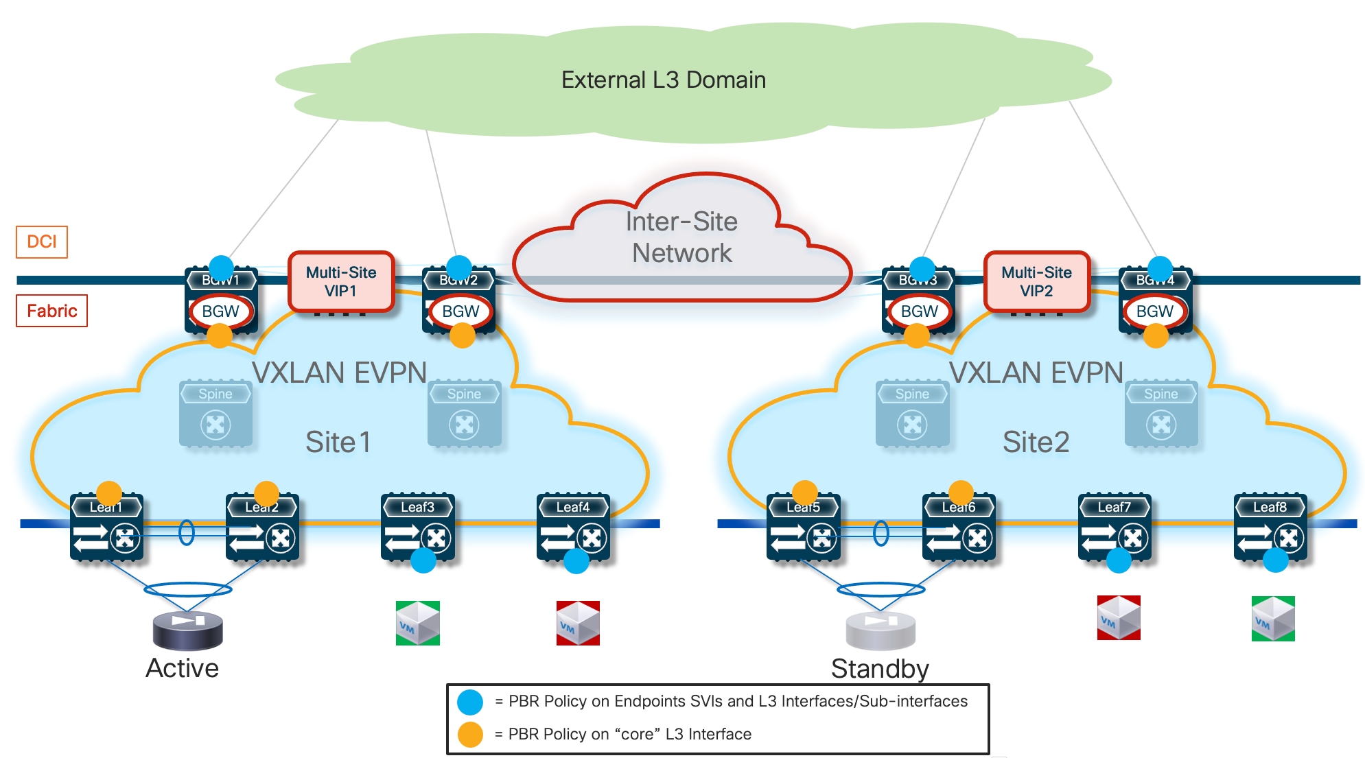
As shown above, the ePBR policy must be applied on the “core” Layer 3 interfaces of the service and BGW nodes to ensure it can be enforced on VXLAN encapsulated traffic received from the fabric uplinks or from the DCI links. The same policy must also be applied to the “edge interfaces” where the user traffic is received. This implies that on compute nodes the policy must be applied to the SVIs of the endpoint subnets, whereas on the border leaf nodes must be applied to the Layer 3 interfaces (or sub-interfaces) connecting to the external network domain.
One very important, and not so obvious, consideration regards the potential creation of routing loops when intersite traffic flows need to be redirected to the firewall service. To better understand the problem, let’s consider an intersite traffic flow originated from an endpoint in Site1 and destined to an endpoint in Site2 (routed communication), taking into considerations all the nodes in the network where the ePBR policy must be applied (as shown in the previous figure above).
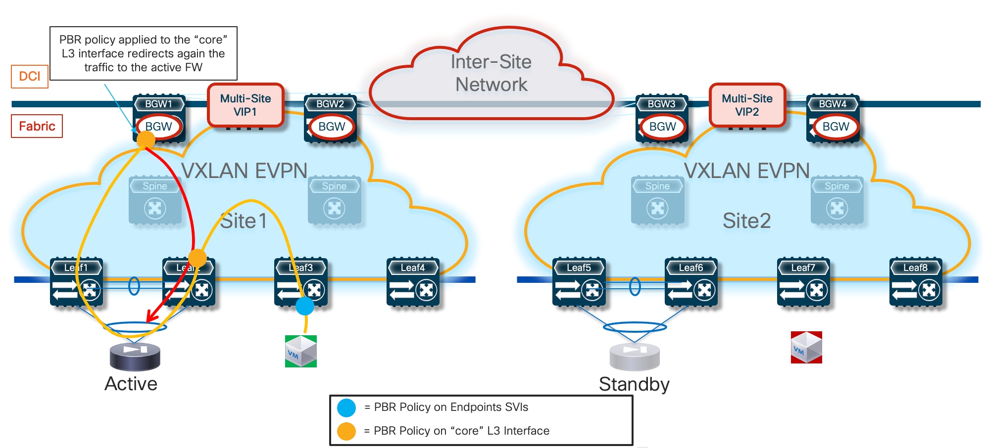
Figure 63 highlights how traffic destined to the endpoint in Site2 and originated from the endpoint in Site1 is first redirected to the active firewall connected in Site1. When the flow is then sent back from the firewall into the fabric and reaches the local BGW node, the ePBR policy applied to the “core” L3 interface of the BGW causes the redirection of the traffic back to the same active firewall in Site1. This behavior consists in a routing loop that does not allow to complete the communication between the endpoints (the IP packet will eventually be dropped once its TTL value reaches zero).
The solution to this fundamental problem consists in ensuring that the ePBR policy is never applied on the BGW nodes of a given fabric if the traffic has already been sent to a firewall service deployed in that site. In the current VXLAN EVPN standard implementation is not possible to carry such information in the data packet, therefore the proposed solution calls for the deployment of a dedicated Service VRF instance specifically used to redirect the traffic to the firewall.
This Service VRF must be extended across the sites, as it represents the routing domain where the active and standby firewall nodes are connected and where the ePBR policy is applied on the “core” Layer 3 interfaces for both the service leaf and BGW nodes. Connectivity between endpoints continues instead to be achieved in the context of the regular tenant VRF. The ePBR policy for the endpoints’ SVIs and the Layer 3 interfaces/sub-interfaces connecting to the external network domain (if redirection is required also for North-South communication) must also be applied in the tenant VRF.
Figure 64 shows how the routing loop problem highlighted in previous Figure 63 is solved adopting this approach. The blue lines represent traffic forwarded in the context of the Tenant VRF, whereas the yellow lines traffic forwarded in the context of the Service VRF.
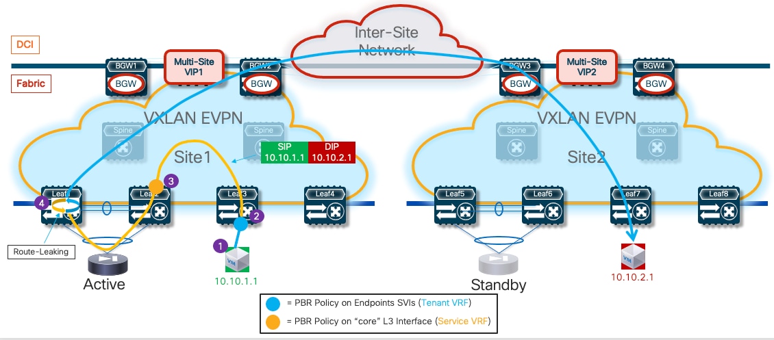
1. The source endpoint in Site1 generates traffic destined to a remote endpoint in Site2.
2. The traffic is received by the compute leaf node 3 and the ePBR policy is applied to the endpoint’s SVI part of the Tenant VRF. The association of the Service VRF to the ePBR policy enables a specific “set-vrf” function on the compute leaf node 3 forcing to perform the lookup for the firewall IP address (and the consequent traffic forwarding) in the context of the Service VRF. The lookup performed in that routing domain for the firewall IP address ensures that traffic is forwarded to the local service leaf nodes 1 and 2 in Site1 where the active firewall is connected.
3. The service leaf node 2 receives the traffic from the uplink, so the ePBR policy associated to the “core” L3 interface in the Service VRF gets applied, forcing the traffic to the firewall device. Notice that the destination IP contained in the packet after it gets decapsulated by the service leaf is still the destination endpoint (10.10.2.1), so the application of the ePBR policy is mandatory to ensure that the traffic can be steered to the firewall.
4. When the traffic from the firewall gets back to the service leaf node, a lookup for the destination IP address (10.10.2.1) is performed in the context of the Service VRF. A route-leaking configuration must be performed on the service leaf nodes to ensure that the Layer 3 lookup returns the information that the next-hop toward the destination is reachable in the context of the Tenant VRF. This “hops back” the traffic into the Tenant VRF routing domain, so that the destination in Site2 can be reached leveraging the intersite connectivity provided by the BGW nodes. The routing loop shown in Figure 63 it is not happening anymore, as the traffic is received by the BGW nodes (in both Site1 and Site2) in the Tenant VRF and no ePBR policy is applied on the BGWs for that VRF.
Figure 65 shows instead the return flow from the endpoint in Site2 to the endpoint in Site1.
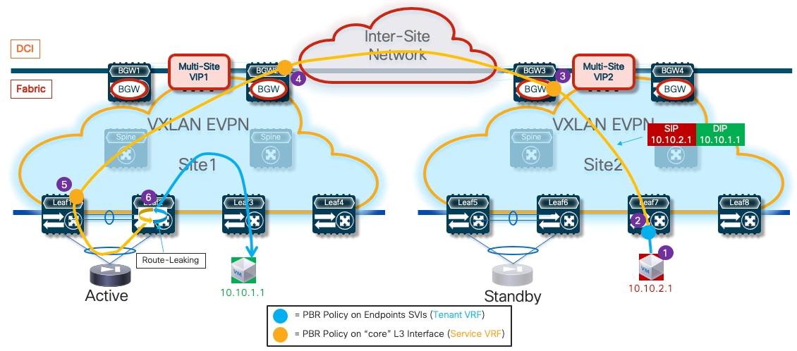
1. The endpoint in Site2 sends traffic back to the remote endpoint in Site1.
2. The return traffic from endpoint 10.10.2.1 is received by the compute leaf 7 and the ePBR policy is applied to the endpoint’s SVI part of the Tenant VRF. As a result of the “set-vrf” function, the lookup for the firewall IP address (and the consequent forwarding) in done again in the Service VRF. Because the active firewall is connected in Site1, the traffic from the compute leaf in Site2 must be sent to the local BGW nodes that advertised reachability information for that IP address (after receiving it from the remote BGWs in Site1).
3. The BGW node receives the packet and the ePBR policy associated to the “core” L3 interface in the Service VRF is applied. The lookup for the active firewall IP is done in the Service VRF and therefore the traffic is sent to the Multi-Site VIP of the BGW nodes in Site1. Notice how applying the ePBR policy on the BGWs in Site2 is critical, as otherwise the traffic will be dropped because the BGW do not have any information in the Service VRF on how to reach the destination endpoint (10.10.1.1) that is part of the Tenant VRF.
4. One of the BGW nodes in Site1 receives the traffic. The ePBR policy associated to the “core” L3 interface in the Service VRF is applied and the traffic is redirected to the local service leaf nodes where the active firewall is connected. Applying the ePBR policy is mandatory for the same reasons mentioned at the previous step 3.
5. The service leaf node receives the traffic from the uplink, so the ePBR policy associated to the “core” L3 interface in the Service VRF gets applied, forcing the redirection of the traffic to the firewall device.
6. When the traffic from the firewall gets back to the service leaf node 2, a lookup for the destination IP address (10.10.1.1) is performed in the context of the Service VRF. The route-leaking configuration performed on the service leaf nodes ensures that the destination is found in that Service VRF, with associated the information that forwarding toward the destination should be done in the context of the Tenant VRF. This brings the traffic back into the Tenant VRF routing domain, so that the destination connected to a local compute leaf node can be reached.
In summary, there are two key functionalities allowing for the proper redirection of intersite traffic flows to the firewall service.
The first one is the capability, built into ePBR, to steer the traffic toward the service node in a different VRF than the one where the policy is applied. This is achieved with the specific configuration shown below (a more complete configuration for the relevant fabric nodes will be shown at the end of this section):
epbr service FW
vrf fw-vrf
service-end-point ip 172.16.1.1
reverse ip 172.16.1.1
epbr policy t1-pbr
statistics
match ip address t1-acl
load-balance method src-ip
10 set service FW
interface Vlan2301
no shutdown
vrf member t1-vrf
ip address 10.10.1.254/24 tag 12345
fabric forwarding mode anycast-gateway
epbr ip policy t1-pbr
epbr ip policy t1-pbr reverse
The command “vrf fw-vrf” and the definition of the firewall node under the policy instruct the leaf to perform the lookup for the service device IP address (and the following traffic forwarding) not in the Tenant VRF of the SVI interface (t1-vrf) where the policy is applied, but in the Service VRF instead.
The second required functionality is the route-leaking performed on the service leaf nodes of the endpoints’ subnets from the Tenant VRF into the Service VRF. This can be simply achieved playing with the route-target values associated to the two VRFs to ensure that prefixes received in the context of the Tenant VRF are imported into the routing table of the Service VRF.
vrf context t1-vrf
vni 50001
rd auto
address-family ipv4 unicast
route-target both auto
route-target both auto evpn
vrf context fw-vrf
vni 50002
rd auto
address-family ipv4 unicast
route-target both auto
route-target both auto evpn
route-target import 65001:50001
route-target import 65001:50001 evpn
The “auto” route-target value for each VRF is generated by concatenating the BGP ASN with the L3VNI of the VRF, and that is the reason why the “import” statements specify the value 65001:50001 in the example above (65001 is the BGP ASN and 50001 is the L3VNI of the Tenant VRF).
Note: In the example above, both the Tenant and the Service VRFs are defined on the service leaf node for the sake of exemplification. The import of the Tenant prefixes into the Service VRF would work also in the case where only the Service VRF was locally defined on the service leaf nodes.
Figure 66 displays the redirection of the same intersite traffic flow already shown in the previous Figure 64, following a firewall failover event that causes the move of the active firewall function to Site2.
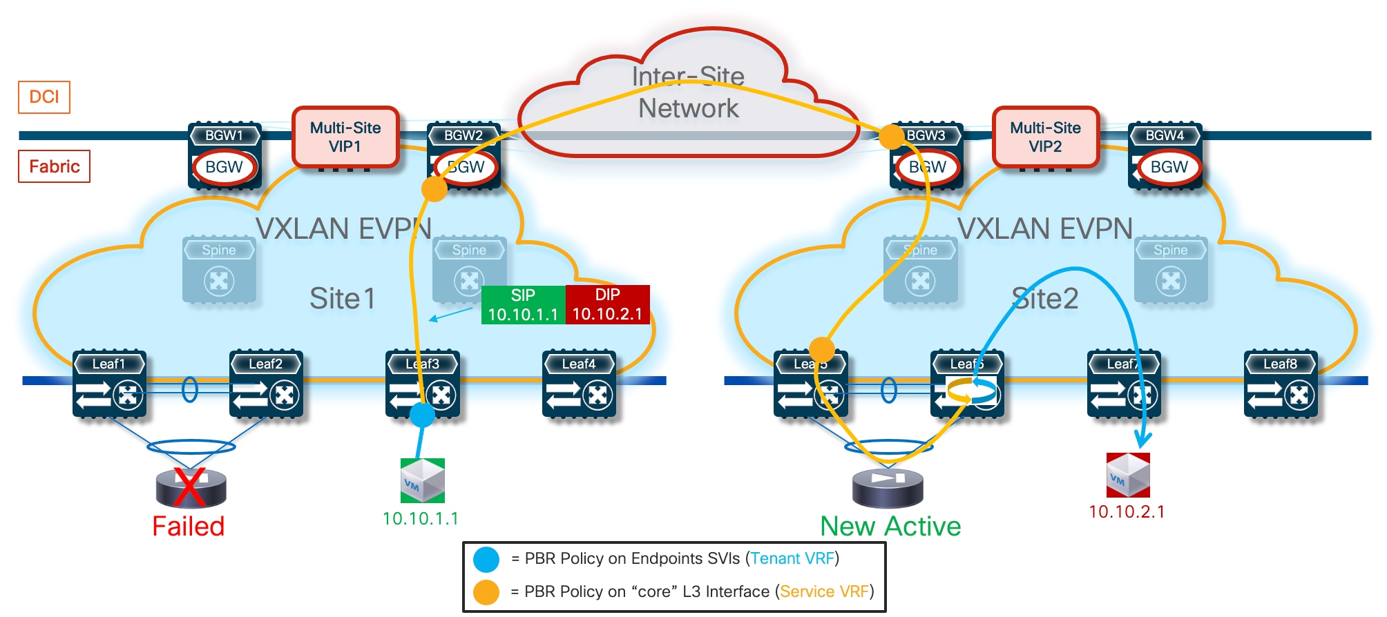
The convergence time is solely dependent on the activation and discovery of the firewall in Site2, as the lookup performed on the various fabric nodes would consequently steer the traffic in that direction.
One of the main drawbacks of the deployment of an Active/Standby firewall cluster stretched across sites is the suboptimal traffic path required when the endpoint and the active firewall are in different sites (Figure 67), which restricts such deployment only across fabrics that are geographically co-located or deployed at limited metro distances. The deployment of an Active/Active firewall cluster (in Split Spanned EtherChannel mode) discussed in the next section offers a solution to this specific problem.
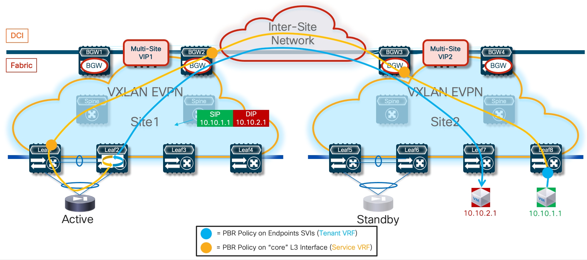
The application of the ePBR policy can also ensure that North-South flows get redirected through the firewall service. The assumption in our example is that the same devices performing the role of BGWs are also configured as Border Leaf nodes to establish Layer 3 connectivity with the external routed domain (similar considerations would apply if dedicated border leaf nodes were deployed). Figure 68 displays the redirection of an outbound traffic flow.
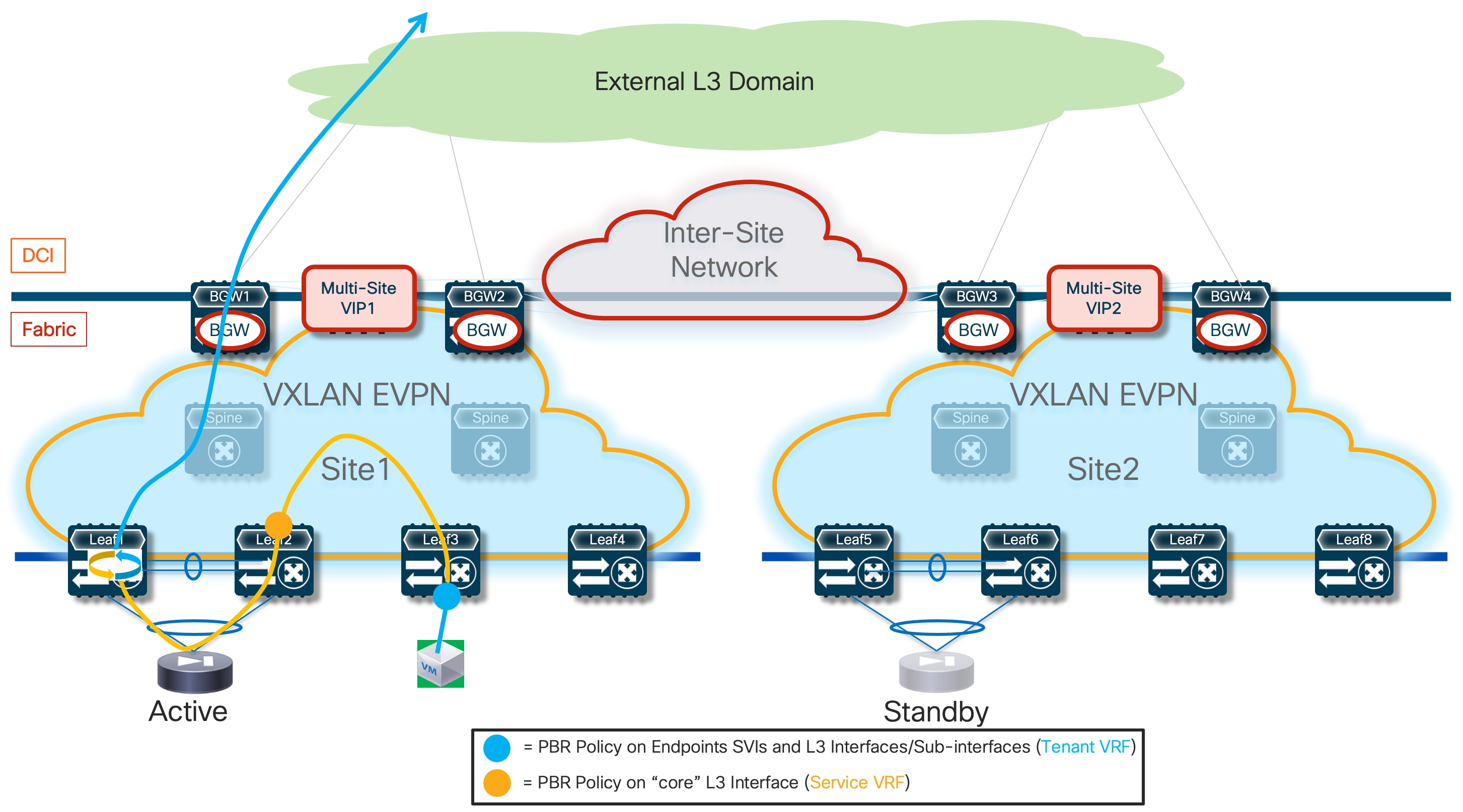
The redirection for the outbound flow happens first on the ingress leaf node where the internal endpoint is connected. This ensures the traffic can be steered, in the Services VRF routing domain, toward the service leaf node where the active firewall is connected. Once the traffic is received on the service node, the ePBR policy is applied again on the core interface to redirect it to the firewall. Traffic returning from the firewall is then leaked back into the Tenant VRF and forwarded toward the external destination via the BGW/Border Leaf nodes.
Figure 69 shows the redirection of the return inbound flow. The ePBR policy must be first applied on the Layer 3 interfaces/sub-interfaces of the BGW/BL nodes connected to the external network and belonging to the Tenant VRF. This redirects the traffic toward the service leaf node (in the Service VRF domain) and from there to the firewall and eventually back to the fabric toward the internal destination endpoint (again in the Tenant VRF domain).
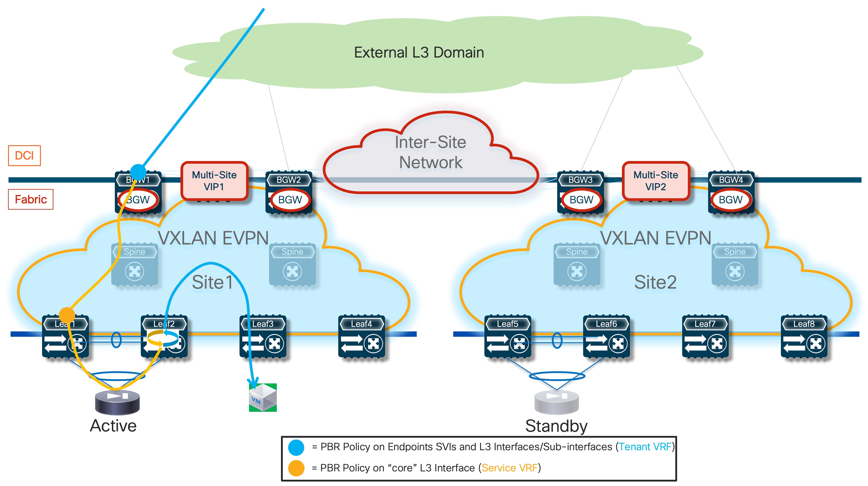
If the return inbound flow was received on the BGW/BL nodes in Site2, the intersite path via ISN would be used to send the traffic toward the active firewall in Site1 (Figure 70).
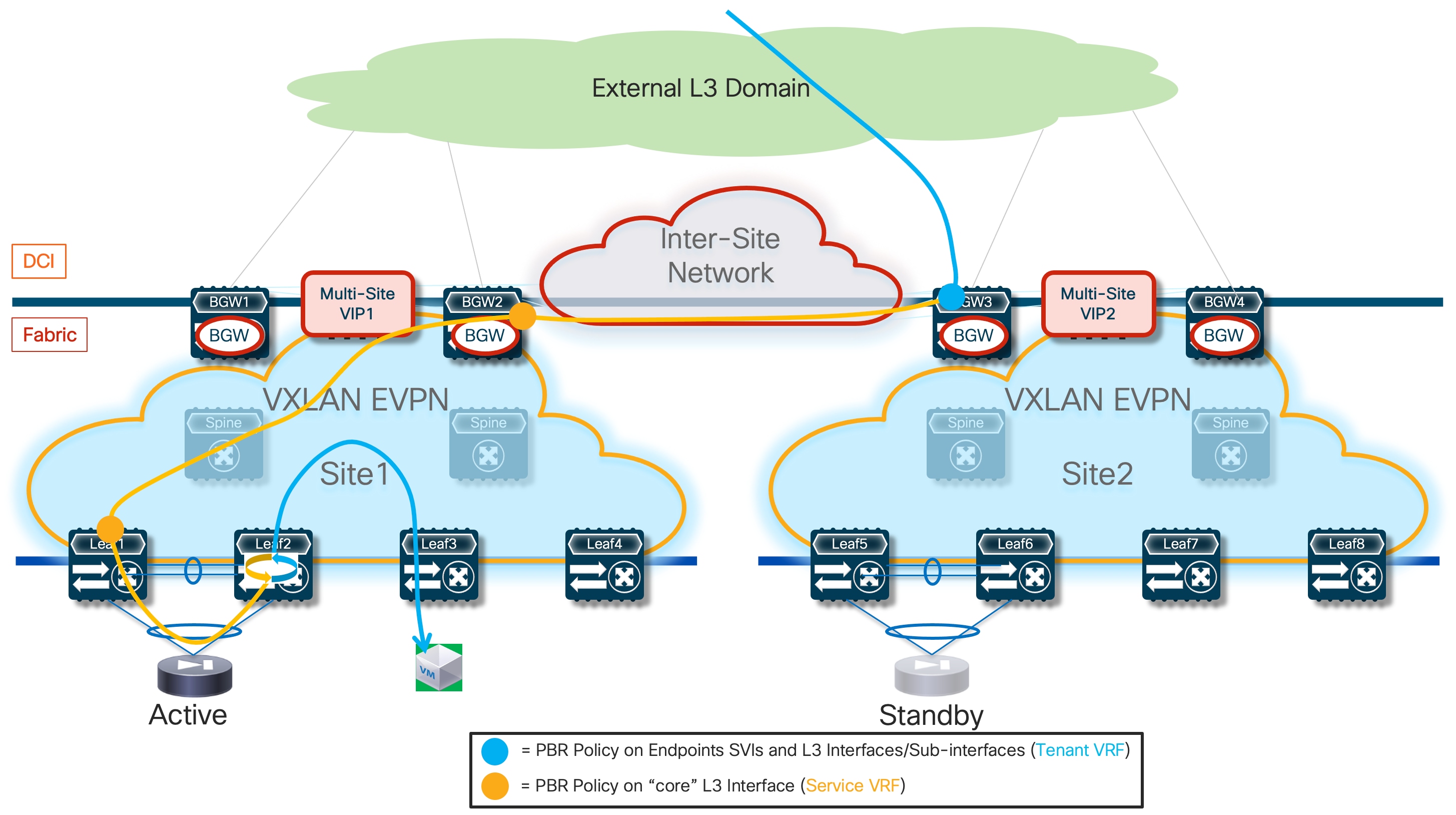
In a Multi-Tenant (Multi-VRF) deployment, the assumption is that a firewall service is dedicated to each tenant for redirecting all the intra-tenant and inter-tenant flows. This implies that the “fusion” function enabling inter-tenant communication is traditionally performed by a routed device external to the tenant domains. Also, this means that an inter-tenant flow would be redirected through both firewall devices belonging to each tenant. The deployment considerations listed here can simply be applied in each tenant domain.
Note: An alternative design could call for the use of a shared firewall performing the “fusion” and security enforcement functions for all inter-tenant communication.
ePBR also offers the capabilities of tracking the health state of the firewall node and taking proper action (permit, drop or bypass) in case of failure of the firewall service. In the specific use case discussed in this section (Active/Standby firewall cluster stretched across sites), a failure of the firewall service would only be possible in the dual case failure scenario where both the active and standby nodes go simultaneously offline. Distributing those nodes across separate fabrics, mapped to different rooms, buildings, or even DC locations, can help minimizing such occurrence.
The tracking of the firewall’s health must be performed from all the fabric devices where the ePBR policy is applied (i.e. compute, BGW, and service leaf nodes). Leveraging the connectivity extension capabilities of VXLAN Multi-Site, leaf nodes deployed in a fabric can verify the good health of the active firewall connected in a remote fabric (i.e. the probing can successfully work across sites). Probes can be sourced from a loopback interface defined in the Service VRF for each fabric’s device. The example below shows the use of ICMP as control plane protocol to verify the firewall’s status from a generic leaf node:
interface loopback10
vrf member fw-vrf
ip address 192.168.1.1/32 tag 12345
epbr service FW
vrf fw-vrf
service-end-point ip 172.16.1.1 interface Vlan3004
probe icmp frequency 4 retry-down-count 1 retry-up-count 1 timeout 2 source-interface loopback10
reverse ip 172.16.1.1 interface Vlan3004
probe icmp frequency 4 retry-down-count 1 retry-up-count 1 timeout 2 source-interface loopback10
It is critical to ensure that the probing messages between the loopback interfaces and the active firewall node do not get redirected by the ePBR policy applied in the context of the Service VRF on the service leaf and BGW nodes. This may become a problem in the specific use case where all intra-VRF flows need to be redirected to the firewall and consequently the access-list associated to the ePBR policy is configured to match all traffic in the VRF. As shown in the sample below, a second access-list is required in this scenario to exclude redirection of probing traffic (in this example ICMP is used as probing protocol between the fabric’s nodes and the firewall nodes):
ip access-list all-traffic
10 permit ip any any
!
ip access-list exclude-probe
10 permit icmp any any
!
epbr policy t1-pbr
statistics
match ip address exclude-probe exclude
match ip address all-traffic
10 set service FW
It is also possible to decide what action to take when the firewall service becomes unavailable (in the specific use case discussed here that would imply that both the Active and Standby service nodes have failed). The possible options valid for this specific use case where traffic is redirected to a single service node (firewall in this use case) are “forward” (the traffic will be normally routed to the destination without redirection) or “drop” (the traffic will be dropped because redirection to the firewall is not possible anymore). The sample below shows the configuration of a “fail close” scenario where the traffic between endpoints will be dropped if the firewall service becomes unavailable.
epbr policy t1-vrf
statistics
match ip address t1-acl
load-balance method src-ip
10 set service FW fail-action drop
It is important to clarify that the detection of failure of one (or more) firewall nodes is possible only when enabling a specific “tracking” mechanism on all the leaf nodes of the fabric. Based on that, specific traffic (for example ICMP probes) is sourced from a loopback interface defined on each leaf node and destined to the firewall IP address.
The decision for which traffic flows should be redirected through the firewall service is very flexible and can be controlled via the definition of an access-list that gets associated to the ePBR policy. The configuration example below shows how to redirect flows between two specific IP subnets but as mentioned above it is also possible to define a generic access-list to redirect all the traffic flows in a VRF (or even flows only matching specific Layer 3 and Layer 4 parameters)..
ip access-list t1-acl
10 permit ip 10.10.1.0/24 10.10.2.0/24 statistics
!
epbr policy t1-pbr
statistics
match ip address t1-acl
load-balance method src-ip
10 set service FW
!
interface Vlan2301
no shutdown
vrf member t1-vrf
ip address 10.10.1.254/24 tag 12345
fabric forwarding mode anycast-gateway
epbr ip policy t1-pbr
epbr ip policy t1-pbr reverse
!
interface Vlan2302
no shutdown
vrf member t1-vrf
ip address 10.10.2.254/24 tag 12345
fabric forwarding mode anycast-gateway
epbr ip policy t1-pbr
epbr ip policy t1-pbr reverse
Notice how the access-list can be defined only to match a specific direction of the traffic (in the example above from subnet 10.10.1.0/24 to subnet 10.10.2.0/24), but also traffic in the opposite direction gets redirected because of the configuration of the “reverse” keyword.
Note how prior to enabling the “epbr” feature, you must enable the “pbr” and “sla sender” features as well.
feature pbr
feature sla sender
feature epbr
All redirection rules are programmed in the ACL TCAM using the ingress RACL region. Depending on the amount of access-control list rules defined, this region may need to be properly carved and allocated prior to the application of ePBR policies. You can leverage the CLI command shown below to verify size of the “Ingress RACL” TCAM space.
show hardware access-list tcam region
NAT ACL[nat] size = 0
Ingress PACL [ing-ifacl] size = 0
VACL [vacl] size = 0
Ingress RACL [ing-racl] size = 1792
Ingress RBACL [ing-rbacl] size = 0
Ingress L2 QOS [ing-l2-qos] size = 256
Ingress L3/VLAN QOS [ing-l3-vlan-qos] size = 512
Ingress SUP [ing-sup] size = 512
Ingress L2 SPAN filter [ing-l2-span-filter] size = 256
Ingress L3 SPAN filter [ing-l3-span-filter] size = 256
Ingress FSTAT [ing-fstat] size = 0
span [span] size = 512
Egress RACL [egr-racl] size = 1792
Egress SUP [egr-sup] size = 256
Ingress Redirect [ing-redirect] size = 0
Ingress Netflow/Analytics [ing-netflow] size = 0
Ingress NBM [ing-nbm] size = 0
TCP NAT ACL[tcp-nat] size = 0
Egress sup control plane[egr-copp] size = 0
Ingress Flow Redirect [ing-flow-redirect] size = 0
MCAST NAT ACL[mcast-nat] size = 0
TCAM region “ing-racl” can be carved using the "hardware access-list tcam region ing-racl <>" command. The changes facilitated with this command only apply to the software allocation. To enforce the reallocation of regions in the hardware, you must reload the system.
Note: For more information on ACL TCAM resource allocation and consumption, please refer to the document below:
https://www.cisco.com/c/en/us/td/docs/dcn/whitepapers/acl-tcam-in-cisco-cloud-scale-asics-for-nexus-9000-series-switches-white-paper.html
Configuration Samples
The samples below capture the relevant configuration on the service leaf nodes, the border gateway node, the compute leaf nodes and on the firewall, in the specific example where the firewall is connected in vPC mode. The reference topology with associated IP addresses is shown in Figure 71.
Note: Similar configuration must be applied to the service leaf nodes connected to the active and standby firewalls. Also, the configuration shown below focuses on the parts that are more relevant for ePBR and does not cover basic VXLAN configuration or endpoints’ subnets definition.
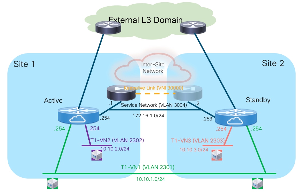
Compute Leaf Nodes
Configure the Tenant and the Service VRFs and the loopback interface, part of the Service VRF, needed for probing the firewall device.
vlan 2001
vn-segment 50001
!
vlan 2002
vn-segment 50002
!
vrf context t1-vrf
vni 50001
rd auto
address-family ipv4 unicast
route-target both auto
route-target both auto evpn
address-family ipv6 unicast
route-target both auto
route-target both auto evpn
!
vrf context fw-vrf
vni 50002
rd auto
address-family ipv4 unicast
route-target both auto
route-target both auto evpn
address-family ipv6 unicast
route-target both auto
route-target both auto evpn
!
interface Vlan2001
no shutdown
mtu 9216
vrf member t1-vrf
no ip redirects
ip forward
ipv6 address use-link-local-only
no ipv6 redirects
!
interface Vlan2002
no shutdown
mtu 9216
vrf member fw-vrf
no ip redirects
ip forward
ipv6 address use-link-local-only
no ipv6 redirects
!
interface loopback10
vrf member fw-vrf
ip address 192.168.1.1/32 tag 12345
!
route-map fabric-rmap-redist-subnet permit 10
match tag 12345
!
router bgp 65001
vrf t1-vrf
address-family ipv4 unicast
advertise l2vpn evpn
redistribute direct route-map fabric-rmap-redist-subnet
maximum-paths 4
address-family ipv6 unicast
advertise l2vpn evpn
redistribute direct route-map fabric-rmap-redist-subnet
maximum-paths 4
vrf fw-vrf
address-family ipv4 unicast
advertise l2vpn evpn
redistribute direct route-map fabric-rmap-redist-subnet
maximum-paths 4
address-family ipv6 unicast
advertise l2vpn evpn
redistribute direct route-map fabric-rmap-redist-subnet
maximum-paths 4
!
interface nve1
member vni 50001 associate-vrf
member vni 50002 associate-vrf
Provision the L2VNI segments representing the subnets where the endpoints are connected.
vlan 2301
vn-segment 30001
!
vlan 2302
vn-segment 30002
!
interface Vlan2301
no shutdown
vrf member t1-vrf
ip address 10.10.1.254/24 tag 12345
fabric forwarding mode anycast-gateway
!
interface Vlan2302
no shutdown
vrf member t1-vrf
ip address 10.10.2.254/24 tag 12345
fabric forwarding mode anycast-gateway
!
interface nve1
member vni 30001
mcast-group 239.1.1.1
member vni 30002
mcast-group 239.1.1.1
!
evpn
vni 30001 l2
rd auto
route-target import auto
route-target export auto
vni 30002 l2
rd auto
route-target import auto
route-target export auto
!
interface port-channel1
description vPC to the ESXi host
switchport mode trunk
switchport trunk allowed vlan 2301-2302
spanning-tree port type edge trunk
spanning-tree bpduguard enable
mtu 9216
vpc 1
Define the required ePBR policies and apply them to the endpoints’ SVIs, part of the tenant VRF (t1-vrf). Notice how the Firewall VRF is configured as part of the definition of the firewall service, to ensure that the traffic can be redirected to the firewall in that specific routing domain. This allows to avoid the traffic looping condition previously shown in Figure 63. Also, a specific ACL entry is added to ensure that all the traffic originated from the internal subnet 10.10.1.0/24 can be redirected to the firewall (no matter if the destination is another internal subnet or an external network).
feature pbr
feature sla sender
feature epbr
!
ip access-list t1-acl
10 permit ip 10.10.1.0/24 0.0.0.0/0
!
epbr service FW
vrf fw-vrf
service-end-point ip 172.16.1.1
probe icmp frequency 4 retry-down-count 1 retry-up-count 1 timeout 2 source-interface loopback10
reverse ip 172.16.1.1
probe icmp frequency 4 retry-down-count 1 retry-up-count 1 timeout 2 source-interface loopback10
!
epbr policy t1-pbr
statistics
match ip address t1-acl
load-balance method src-ip
10 set service FW fail-action drop
!
interface Vlan2301
epbr ip policy t1-pbr
epbr ip policy t1-pbr reverse
interface Vlan2302
epbr ip policy t1-pbr
epbr ip policy t1-pbr reverse
Service Leaf Nodes
Configure the Tenant and the Service VRFs and the loopback interface needed for probing. As previously explained, specific configuration is also required to ensure that the endpoints’ subnet in the Tenant VRF (t1-vrf) can be leaked to the Service VRF (fw-vrf).
vlan 2001
vn-segment 50001
!
vlan 2002
vn-segment 50002
!
vrf context t1-vrf
vni 50001
rd auto
address-family ipv4 unicast
route-target both auto
route-target both auto evpn
address-family ipv6 unicast
route-target both auto
route-target both auto evpn
!
vrf context fw-vrf
vni 50002
rd auto
address-family ipv4 unicast
route-target both auto
route-target both auto evpn
route-target import 65001:50001
route-target import 65001:50001 evpn
address-family ipv6 unicast
route-target both auto
route-target both auto evpn
!
interface Vlan2001
no shutdown
mtu 9216
vrf member t1-vrf
no ip redirects
ip forward
ipv6 address use-link-local-only
no ipv6 redirects
!
interface Vlan2002
no shutdown
mtu 9216
vrf member fw-vrf
no ip redirects
ip forward
ipv6 address use-link-local-only
no ipv6 redirects
!
interface loopback10
vrf member fw-vrf
ip address 192.168.1.2/32 tag 12345
!
route-map fabric-rmap-redist-subnet permit 10
match tag 12345
!
router bgp 65001
vrf t1-vrf
address-family ipv4 unicast
advertise l2vpn evpn
redistribute direct route-map fabric-rmap-redist-subnet
maximum-paths 4
address-family ipv6 unicast
advertise l2vpn evpn
redistribute direct route-map fabric-rmap-redist-subnet
maximum-paths 4
vrf fw-vrf
address-family ipv4 unicast
advertise l2vpn evpn
redistribute direct route-map fabric-rmap-redist-subnet
maximum-paths 4
address-family ipv6 unicast
advertise l2vpn evpn
redistribute direct route-map fabric-rmap-redist-subnet
maximum-paths 4
!
interface nve1
member vni 50001 associate-vrf
member vni 50002 associate-vrf
Define the L2VNI segment used as firewall Keepalive Link (vn-segment 30000, Layer-2 only) and the Service Network to connect to the firewall node.
vlan 2300
vn-segment 30000
!
vlan 3004
vn-segment 30004
!
interface Vlan3004
no shutdown
vrf member t1-vrf
ip address 172.16.1.254/24 tag 12345
fabric forwarding mode anycast-gateway
!
interface nve1
member vni 30000
mcast-group 239.1.1.1
member vni 30004
mcast-group 239.1.1.1
!
evpn
vni 30000 l2
rd auto
route-target import auto
route-target export auto
vni 30004 l2
rd auto
route-target import auto
route-target export auto
!
interface port-channel
description vPC to the Firewall Node
switchport mode trunk
switchport trunk allowed vlan 2300,3004
Define the required ePBR policies and apply them to the “core” Layer 3 interface part of the Service VRF (fw-vrf).
feature pbr
feature sla sender
feature epbr
!
ip access-list t1-acl
10 permit ip 10.10.1.0/24 10.10.2.0/24
20 permit ip 10.10.1.0/24 0.0.0.0/0
!
epbr service FW
vrf fw-vrf
service-end-point ip 172.16.1.1 interface Vlan3004
probe icmp frequency 4 retry-down-count 1 retry-up-count 1 timeout 2 source-interface loopback10
reverse ip 172.16.1.1 interface Vlan3004
probe icmp frequency 4 retry-down-count 1 retry-up-count 1 timeout 2 source-interface loopback10
!
epbr policy t1-pbr
statistics
match ip address t1-acl
load-balance method src-ip
10 set service FW fail-action drop
!
interface Vlan2002
no shutdown
mtu 9216
vrf member fw-vrf
no ip redirects
ip forward
ipv6 address use-link-local-only
epbr ip policy t1-pbr
epbr ip policy t1-pbr reverse
BGW Nodes
Define the Tenant and the Service VRFs that need to be stretched across sites and the loopback interface needed for probing. Also, configure the Layer 3 interfaces connecting with the external network.
vlan 2001
vn-segment 50001
!
vlan 2002
vn-segment 50002
!
vrf context t1-vrf
vni 50001
rd auto
address-family ipv4 unicast
route-target both auto
route-target both auto evpn
address-family ipv6 unicast
route-target both auto
route-target both auto evpn
!
vrf context fw-vrf
vni 50002
rd auto
address-family ipv4 unicast
route-target both auto
route-target both auto evpn
address-family ipv6 unicast
route-target both auto
route-target both auto evpn
!
interface Vlan2001
no shutdown
mtu 9216
vrf member t1-vrf
no ip redirects
ip forward
ipv6 address use-link-local-only
no ipv6 redirects
!
interface Vlan2002
no shutdown
mtu 9216
vrf member fw-vrf
no ip redirects
ip forward
ipv6 address use-link-local-only
no ipv6 redirects
!
interface loopback10
vrf member fw-vrf
ip address 192.168.1.2/32 tag 12345
!
interface Ethernet1/35.2
mtu 9216
encapsulation dot1q 2
vrf member t1-vrf
ip address 10.33.0.1/30
no shutdown
!
route-map fabric-rmap-redist-subnet permit 10
match tag 12345
!
router bgp 65001
vrf t1-vrf
address-family ipv4 unicast
advertise l2vpn evpn
redistribute direct route-map fabric-rmap-redist-subnet
maximum-paths 4
address-family ipv6 unicast
advertise l2vpn evpn
redistribute direct route-map fabric-rmap-redist-subnet
maximum-paths 4
vrf fw-vrf
address-family ipv4 unicast
advertise l2vpn evpn
redistribute direct route-map fabric-rmap-redist-subnet
maximum-paths 4
address-family ipv6 unicast
advertise l2vpn evpn
redistribute direct route-map fabric-rmap-redist-subnet
maximum-paths 4
!
interface nve1
member vni 50001 associate-vrf
member vni 50002 associate-vrf
Define the L2VNIs that need to be stretched across sites.
vlan 2300
vn-segment 30000
!
vlan 2301
vn-segment 30001
!
vlan 3004
vn-segment 30004
!
interface nve1
member vni 30000
mcast-group 239.1.1.1
member vni 30001
mcast-group 239.1.1.1
member vni 30004
mcast-group 239.1.1.1
!
evpn
vni 30000 l2
rd auto
route-target import auto
route-target export auto
vni 30001 l2
rd auto
route-target import auto
route-target export auto
vni 30004 l2
rd auto
route-target import auto
route-target export auto
Define the required ePBR policies and apply them to the “core” Layer 3 interface part of the Service VRF (fw-vrf) and to the Layer 3 interface connecting to the external network. The assumption is that VXLAN encapsulated traffic will never reach the BGW in the context of the Service VRF, unless the active firewall node is located in a remote fabric (or directly connected to the BGW if deployed as part of a vPC domain – vPC BGW).
feature pbr
feature sla sender
feature epbr
!
ip access-list t1-acl
10 permit ip 10.10.1.0/24 0.0.0.0/0
!
epbr service FW
vrf fw-vrf
service-end-point ip 172.16.1.1
probe icmp frequency 4 retry-down-count 1 retry-up-count 1 timeout 2 source-interface loopback10
reverse ip 172.16.1.1
probe icmp frequency 4 retry-down-count 1 retry-up-count 1 timeout 2 source-interface loopback10
!
epbr policy t1-pbr
statistics
match ip address t1-acl
load-balance method src-ip
10 set service FW fail-action drop
!
interface Vlan2002
no shutdown
mtu 9216
vrf member fw-vrf
no ip redirects
ip forward
ipv6 address use-link-local-only
epbr ip policy t1-pbr
epbr ip policy t1-pbr reverse
!
interface Ethernet1/35.2
epbr ip policy t1-pbr
epbr ip policy t1-pbr reverse
Firewall Nodes
The configuration sample below is taken from a Cisco ASA model. This configuration can be easily adapted to apply to different types of firewall devices (physical or virtual form factors). Also, the assumption is that the required failover configuration has already been applied to build an Active/Standby firewall pair, as described in the previous “Active/Standby Firewall Cluster Stretched across Sites” section.
The configuration of the firewall nodes for this use case is quite straightforward, as there is no requirement to enable any control plane protocol and a single interface is needed to connect the firewall to the Service Network (one-arm model). A simple default route is used to send the traffic back to the fabric. The “same-security-traffic permit intra-interface” command is required to allow reception and transmission of traffic using the same one-arm interface.
interface Port-channel2.3004
vlan 3004
nameif one-arm
security-level 100
ip address 172.16.1.254 255.255.255.0 standby 172.16.1.253
!
same-security-traffic permit intra-interface
!
access-list permit-any extended permit ip any any
access-group permit-any in interface one-arm
!
route one-arm 0.0.0.0 0.0.0.0 172.16.1.254 1
Configuration Verification
Below are some relevant CLI commands that can be used to verify that the applied ePBR configuration is working properly.
show ip access-lists dynamic
This command displays the access-lists that are created to match the traffic for both the directions of the flow (as previously show, the ACL that is configured can instead only specify one specific direction).
Fabric-1-Leaf-1# show access-lists dynamic
IP access list epbr_t1-pbr_1_fwd_bucket_1
10 permit ip 10.10.1.0 0.0.0.255 10.10.2.0 0.0.0.255
IP access list epbr_t1-pbr_1_rev_bucket_1
10 permit ip 10.10.2.0 0.0.0.255 10.10.1.0 0.0.0.255
Notice how for both the forward and reverse directions, the ACL is associated to the same “bucket”, because in the specific Active/Standby firewall example we are discussing, a single IP address (the active firewall) is associated to the configured service. For more information on use cases that may require the use of multiple buckets, please refer to the document below:
https://www.cisco.com/c/en/us/products/collateral/switches/nexus-9000-series-switches/layer4-layer7-service-redir-ply-based-redir-wp.html
show route-map dynamic
This command displays the route-map that are dynamically created on the compute leaf nodes, service leaf nodes, or BGW nodes.
For example, on a compute node, where the ePBR policy is only applied to the endpoint subnet (VLAN 2301), the output shows how the lookup for steering the traffic toward the active firewall is forced to be performed in the Service VRF via the definition of “set-vrf” clauses.
Fabric-1-Leaf-1# show route-map dynamic
route-map epbr_rmap_v4_Vlan2301, permit, sequence 701
Match clauses:
ip address (access-lists): epbr_t1-pbr_1_fwd_bucket_1
Set clauses:
ip vrf fw-vrf next-hop verify-availability 172.16.1.1 track 1 [ UP ] force-order drop-on-fail
route-map epbr_rmap_v4_Vlan2301, permit, sequence 1051
Match clauses:
ip address (access-lists): epbr_t1-pbr_1_rev_bucket_1
Set clauses:
ip vrf max-fw-vrf next-hop verify-availability 172.16.1.1 track 2 [ UP ] force-order drop-on-fail
The same command issued on a service leaf node or on a BGW node shows similar information, now relative to the “core” Layer 3 interface (VLAN 2002).
Fabric-1-Leaf-3# show route-map dynamic
route-map epbr_rmap_v4_Vlan2002, permit, sequence 701
Match clauses:
ip address (access-lists): epbr_t1-pbr_1_fwd_bucket_1
Set clauses:
ip vrf fw-vrf next-hop verify-availability 172.16.1.1 track 1 [ UP ] force-order
route-map epbr_rmap_v4_Vlan2002, permit, sequence 1051
Match clauses:
ip address (access-lists): epbr_t1-pbr_1_rev_bucket_1
Set clauses:
ip vrf fw-vrf next-hop verify-availability 172.16.1.1 track 2 [ UP ] force-order
show epbr policy <policy_name>
This command allows to display specific ePBR policy information, including the health status for the service node. The health status must be shown as “UP” for the ePBR policy to actively redirect traffic to such service.
Fabric-1-Leaf-1# show epbr policy t1-pbr
Policy-map : t1-pbr
Match clause:
ip address (access-lists): t1-acl
action:Redirect
service FW, sequence 10, fail-action Drop
IP 172.16.1.1 track 1 [UP]
Policy Interfaces:
Vlan2301
show epbr statistics policy <policy_name> [reverse]
The output of this command allows to verify that the traffic is being redirected to the defined firewall node. The counter must increase when traffic is flowing, and “Redirect” must be show next to the counter. The direction of the traffic redirected is the one that specifically matches the configured ACL: in our specific example, “t1-acl” specified traffic from subnet 10.10.1.0/24 to 10.10.2.0/24.
Fabric-1-Leaf-1# show epbr statistics policy t1-pbr
Policy-map t1-pbr, match t1-acl
Bucket count: 1
traffic match : bucket 1
FW : 211922 (Redirect)
Note: At the time of writing of this document (up to NX-OS release 10.4(1)), the counter shown in the example above increases only on the compute leaf nodes, where the ePBR policy is applied on the endpoint subnet. The output for service leaf and BGW nodes (where the policy is applied on the “core” L3 interface) shown “0” instead, this problem will be fixed in a future NX-OS release.
If the firewall service becomes unavailable, the configured “drop” action gets activated and the traffic starts getting dropped, as shown in the output below:
Fabric-1-Leaf-1# show epbr statistics policy t1-pbr
Policy-map t1-pbr, match t1-acl
Bucket count: 1
traffic match : bucket 1
FW : 151 (Drop)
Finally, the “reverse” option for the command should be used to verify redirection of traffic flows in the opposite direction of what specified in the access-list. Below is the output of the command (with and without the “reverse” option) issued on a compute leaf where only the subnet 10.10.2.0/24 is deployed, in our specific example where the ACL matches traffic between 10.10.1.0/24 and 10.10.2.0/24.
Fabric-2-Leaf-4# show epbr statistics policy t1-pbr
Policy-map t1-pbr, match t1-acl
Bucket count: 1
traffic match : bucket 1
FW : 0 (N/A)
Fabric-2-Leaf-4# show epbr statistics policy t1-pbr reverse
Policy-map t1-pbr, match t1-acl
Bucket count: 1
traffic match : bucket 1
FW : 108 (Redirect)
As expected, the counter shows “0” in the “direct” direction, as the ePBR policy on this leaf node is only applied to return flows between subnets 10.10.2.0/24 and 10.10.1.0/24.
ePBR and Active/Active Firewall Cluster Stretched across Sites
The use of ePBR with an Active/Standby cluster stretched across sites discussed in the previous section has the main drawback that only one firewall node is utilized (at least on a per tenant basis) at any given point in time, whereas the second node remains inactive. Also, depending on the location of the endpoints in a Multi-Site deployment, traffic may be hair-pinned across sites in a suboptimal way.
A more scalable and efficient approach calls for the deployment of an Active/Active firewall cluster that allows you to alleviate the problems mentioned above. The two sections below discuss in greater detail the use of ePBR with an Active/Active firewall cluster in both deployment models called “Split Spanned EtherChannel” and “Individual Interface”.
Split-Spanned EtherChannel Cluster Mode
The deployment of an Active/Active firewall cluster stretched across sites leveraging “Split Spanned EtherChannel” mode represents the natural evolution of the Active/Standby cluster deployment model discussed in the previous section.
Because the entire cluster is seen as a single vMAC/vIP addresses pair, the required ePBR functionalities (and the configuration provisioning) are the same, with the advantages in terms of resources utilization and failover time due to the use of a multi-node active/active cluster.
Refer to the “Split Spanned EtherChannels Active/Active Firewall Cluster Mode” section in the beginning of this document for more information on how to connect the firewall nodes to the fabrics, how to configure them so they can all successfully join the cluster, and how to leverage the EVPN multi-homing functionalities to ensure that the same vMAC/vIP addresses pair can be simultaneously learned in different fabrics without being seen as an “live endpoint migration” event.
Assuming the active/active firewall cluster is up and running, the use of ePBR allows to redirect all, or a specific subset, of the East-West and North-South traffic flows between endpoints part of the same tenant/VRF.
Figure 72 shows the physical and logical topology with the Active/Active firewall cluster stretched across fabrics and connected in one-arm mode to the fabric leaf nodes. As previously discussed in this paper, the use of the one-arm deployment model is recommended when using ePBR as it greatly simplifies the routing configuration required on the fabric.
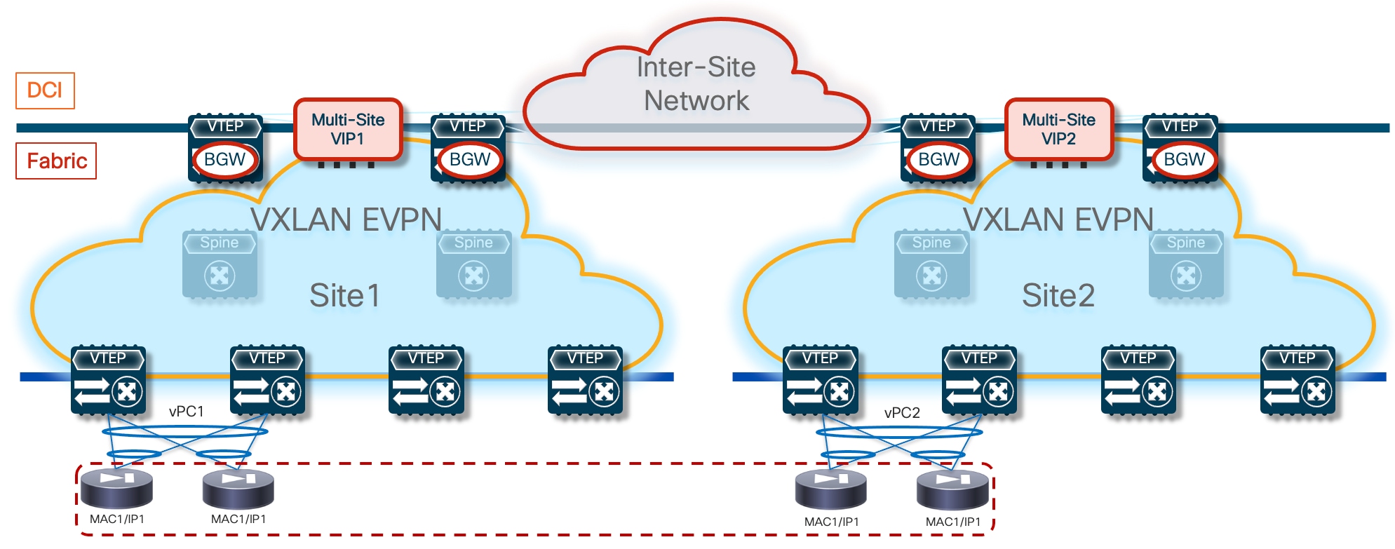
Most of the deployment considerations covered in the “ePBR and Active/Standby Firewall Cluster Stretched across Sites” continue to apply in this use case and are summarized below (we recommend referencing the earlier section for more details), together with new considerations specifically relevant for the Active/Active use case.
The firewall nodes are deployed as Layer 3 devices connected in one-arm mode to the fabrics via a Service Network segment that must be stretched across sites leveraging the BGW network extension capabilities.
● From a physical connectivity perspective, all the firewall nodes deployed in the same fabric must be connected to the same logical vPC connection defined on the same pair of vPC service nodes.
● Configuration and health state information is exchanged between the firewall nodes via a dedicated Cluster Control Link (CCL). Each cluster node should dedicate at least one hardware interface (better if two bundled in a port-channel) as CCL. CCL connectivity between the nodes of the cluster is established intra-fabric and inter-fabric leveraging the Layer 2 extension capabilities of VXLAN EVPN.
Similarly to the Active/Standby use case, the whole Active/Active firewall cluster is modeled as a single logical device connected to a dedicate Service VRF (fw-vrf). In the configuration sample shown below a single vIP address is assigned to the one-arm data interface defined on all the firewall devices part of the same cluster (together with a vMAC address).
epbr service FW-Cluster
vrf fw-vrf
service-end-point ip 172.16.1.1 interface Vlan3004
reverse ip 172.16.1.1 interface Vlan3004
The ePBR policy must be applied on the fabric switches (compute leaf nodes, service leaf nodes, BGW and Border Leaf nodes). The “edge” interfaces should belong to the Tenant VRF, whereas the Layer 3 “core” interfaces should be part of a separate Service VRF, where the interfaces of the firewall nodes are also connected. As discuss in detail for the Active/Standby firewall cluster deployment, the use of a dedicated Service VRF is mandatory to avoid the creation of routing loops when redirecting traffic flows between endpoints connected to different fabrics (see Figure 63 for details).
In contrast with the Active/Standby scenario, traffic flows can now be optimized and firewall services in a specific fabric or in both the source and destination fabrics are used depending on the location of the endpoints. Figure 73 highlights how the local firewall nodes are always preferred for redirecting traffic flows between endpoints locally connected in that same site. The decision on what specific local cluster node to use is made by the service leaf nodes based on port-channel hashing; the hashing decision depends on the 5-tuple information in the header of the original packet. While the figure below shows the use of the same cluster node for both legs of the same flow, it is possible that the two legs of the flow are redirected to the two different local nodes. However, this does not represent a problem, as there is an intra-cluster traffic redirection logic leveraging the CCL to ensure that both the legs of the flows are steered through the same cluster node, representing the “owner” of that specific flow. The intra-cluster data-plane traffic redirection happens via CCL, so it is important to keep this into consideration to properly size the bandwidth required for that connectivity.
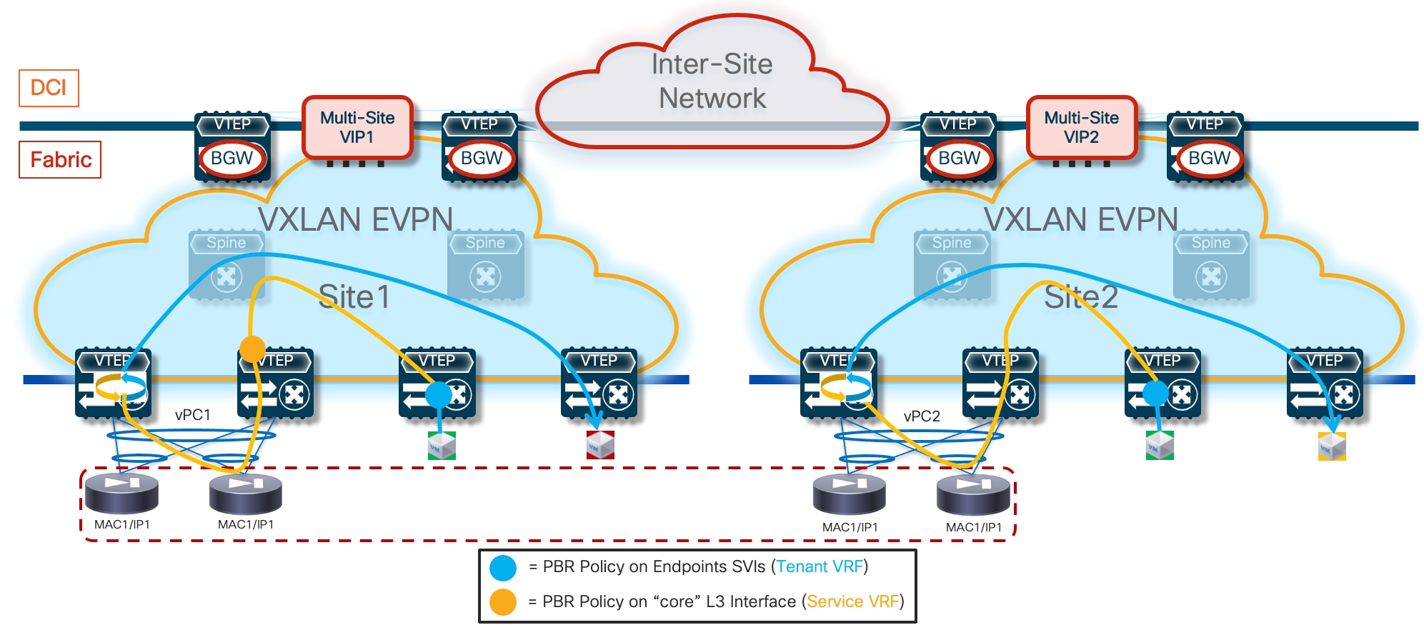
Redirection of intersite flows requires taking advantage of the intra-cluster traffic redirection capabilities to be able to stitch the two legs of the traffic through the firewall node that owns that session. To better understand this, let’s consider the scenario where a TCP session is established between two endpoints connected in different sites. Figure 74 shows the TCP SYN packet originated by the endpoint in Site1 and redirected to a local firewall node before reaching the destination endpoint in Site2. The firewall node in Site1 hence becomes the “owner” of that TCP connection.
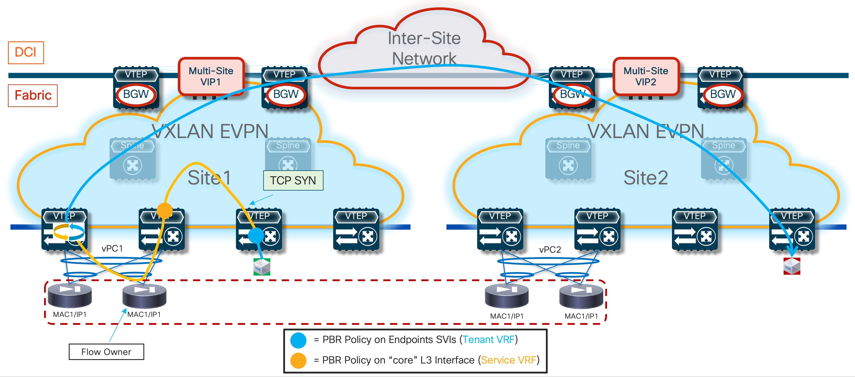
When the endpoint in Site2 replies with a TCP SYN-ACK message, that packet is redirected to one of the local firewall service nodes in Site2. Because that firewall is not the owner of the session, it will use the intra-cluster redirection mechanism via the CCL link to send the traffic back to the owner in Site1, which will then forward the traffic toward the destination (Figure 75).
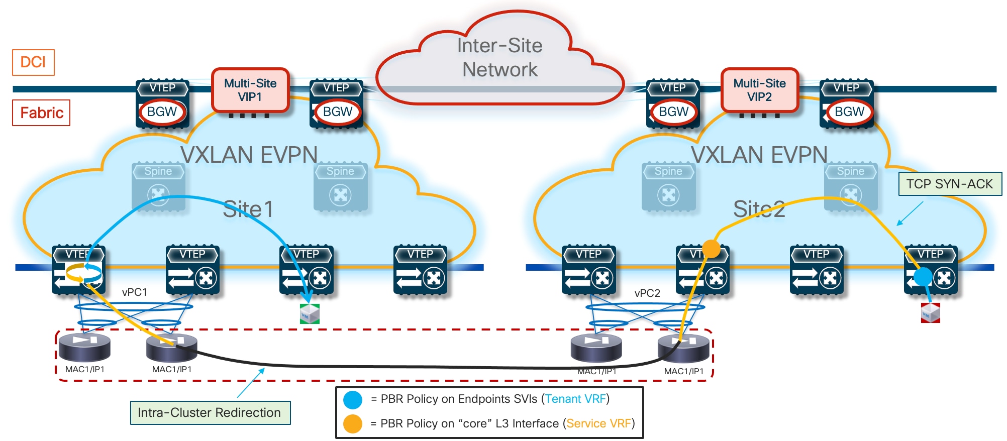
Note: The intra-cluster redirection is shown in a logical way in the figure above. The traffic flow is taking the path via the BGW nodes and the ISN network in the L2VNI network where the CCL interfaces of the firewall cluster nodes are connected.
If a firewall node fails, the traffic flows will be redirected to another of the firewall nodes deployed in the same site. If all the local cluster nodes in a site fail, the traffic will instead be redirected to one of the firewall nodes deployed in a remote site. The convergence is solely driven by the underlay traffic re-routing following the vIP address information received from the BGW nodes in the remote site (Figure 76).
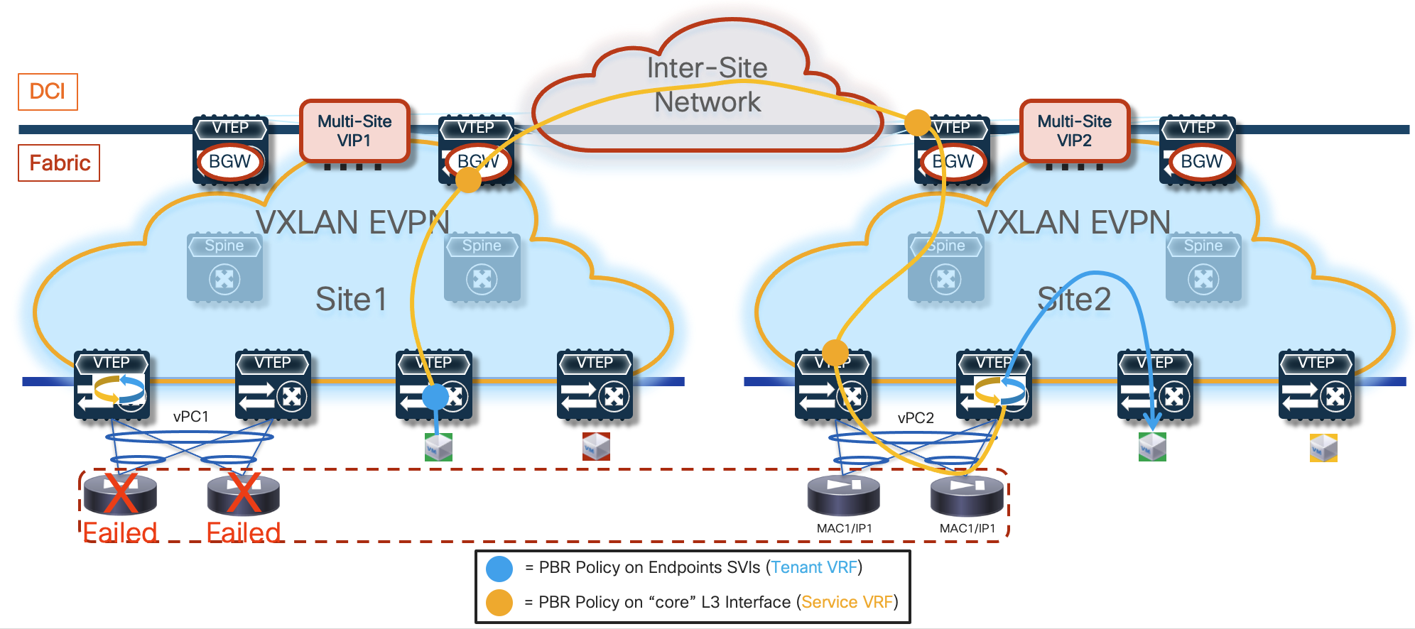
The configuration of the tracking of the firewall’s health, while still required, is less relevant in this specific use case, as the only scenario where the probing would fail is if all the nodes (local and remote) part of the same cluster were to fail, or if all the local nodes were to fail and connectivity to remote firewall nodes was impaired because of an outage in the ISN. Both cases represent very unlikely corner case scenarios.
It is critical to ensure that the probing messages between the loopback interfaces and the active firewall node do not get redirected by the PBR policies applied in the context of the Service VRF on the service leaf and BGW nodes. This may become a problem when the access-list associated to the ePBR policy is configured to match all the traffic flows in a VRF. In this scenario it is required to configure a second access-list to exclude the probing traffic.
Redirection to the firewall can be done for both East-West and North-South traffic flows. For the latter scenario, the ePBR policy must be applied on the border leaf nodes to the Layer 3 interfaces/sub-interfaces connecting to the external network domain.
Configuration Samples
The samples below capture the relevant configuration on the compute nodes, the service leaf nodes, the border gateway (and border leaf) nodes, and the firewall. Tthe reference topology with associated IP addresses is shown in Figure 77.
Note: Similar configuration must be applied to all the service leaf nodes deployed across fabrics where the firewall nodes part of the same Active/Active cluster are connected. Note that the configuration shown below focuses on the parts that are more relevant for ePBR and does not cover basic VXLAN configuration or endpoints’ subnets definition.
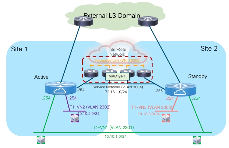
Compute Leaf Nodes
Define the Tenant and the Service VRFs and the loopback interface needed for probing.
vlan 2001
vn-segment 50001
!
vlan 2002
vn-segment 50002
!
vrf context t1-vrf
vni 50001
rd auto
address-family ipv4 unicast
route-target both auto
route-target both auto evpn
address-family ipv6 unicast
route-target both auto
route-target both auto evpn
!
vrf context fw-vrf
vni 50002
rd auto
address-family ipv4 unicast
route-target both auto
route-target both auto evpn
address-family ipv6 unicast
route-target both auto
route-target both auto evpn
!
interface Vlan2001
no shutdown
mtu 9216
vrf member t1-vrf
no ip redirects
ip forward
ipv6 address use-link-local-only
no ipv6 redirects
!
interface Vlan2002
no shutdown
mtu 9216
vrf member fw-vrf
no ip redirects
ip forward
ipv6 address use-link-local-only
no ipv6 redirects
!
interface loopback10
vrf member fw-vrf
ip address 192.168.1.1/32 tag 12345
!
route-map fabric-rmap-redist-subnet permit 10
match tag 12345
!
router bgp 65001
vrf t1-vrf
address-family ipv4 unicast
advertise l2vpn evpn
redistribute direct route-map fabric-rmap-redist-subnet
maximum-paths 4
address-family ipv6 unicast
advertise l2vpn evpn
redistribute direct route-map fabric-rmap-redist-subnet
maximum-paths 4
vrf fw-vrf
address-family ipv4 unicast
advertise l2vpn evpn
redistribute direct route-map fabric-rmap-redist-subnet
maximum-paths 4
address-family ipv6 unicast
advertise l2vpn evpn
redistribute direct route-map fabric-rmap-redist-subnet
maximum-paths 4
!
interface nve1
member vni 50001 associate-vrf
member vni 50002 associate-vrf
Define the L2VNI segments representing the subnets where the endpoints are connected.
vlan 2301
vn-segment 30001
!
vlan 2302
vn-segment 30002
!
interface Vlan2301
no shutdown
vrf member t1-vrf
ip address 10.10.1.254/24 tag 12345
fabric forwarding mode anycast-gateway
!
interface Vlan2302
no shutdown
vrf member t1-vrf
ip address 10.10.2.254/24 tag 12345
fabric forwarding mode anycast-gateway
!
interface nve1
member vni 30001
mcast-group 239.1.1.1
member vni 30002
mcast-group 239.1.1.1
!
evpn
vni 30001 l2
rd auto
route-target import auto
route-target export auto
vni 30002 l2
rd auto
route-target import auto
route-target export auto
!
interface port-channel1
description vPC to the ESXi host
switchport mode trunk
switchport trunk allowed vlan 2301-2302
spanning-tree port type edge trunk
spanning-tree bpduguard enable
mtu 9216
vpc 1
Define the required ePBR policies and apply them to the endpoints’ SVIs, part of the tenant VRF (t1-vrf). Notice how the firewall VRF is configured as part of the “onboarding” of the firewall service to ensure that the traffic can be redirected to the firewall in that specific routing domain. This avoids the traffic looping condition previously shown in Figure 63.
feature pbr
feature sla sender
feature epbr
!
ip access-list t1-acl
10 permit ip 10.10.1.0/24 10.10.2.0/24
!
epbr service FW-Cluster
vrf fw-vrf
service-end-point ip 172.16.1.1
probe icmp frequency 4 retry-down-count 1 retry-up-count 1 timeout 2 source-interface loopback10
reverse ip 172.16.1.1
probe icmp frequency 4 retry-down-count 1 retry-up-count 1 timeout 2 source-interface loopback10
!
epbr policy t1-pbr
statistics
match ip address t1-acl
load-balance method src-ip
10 set service FW-Cluster fail-action drop
!
interface Vlan2301
epbr ip policy t1-pbr
epbr ip policy t1-pbr reverse
interface Vlan2302
epbr ip policy t1-pbr
epbr ip policy t1-pbr reverse
Service Leaf Nodes
Define the Tenant and the Service VRFs and the loopback interface needed for probing. Specific configuration is also required to ensure that the endpoints’ subnet in the Tenant VRF (t1-vrf) can be leaked to the Service VRF (fw-vrf).
vlan 2001
vn-segment 50001
!
vlan 2002
vn-segment 50002
!
vrf context t1-vrf
vni 50001
rd auto
address-family ipv4 unicast
route-target both auto
route-target both auto evpn
address-family ipv6 unicast
route-target both auto
route-target both auto evpn
!
vrf context fw-vrf
vni 50002
rd auto
address-family ipv4 unicast
route-target both auto
route-target both auto evpn
route-target import 65001:50001
route-target import 65001:50001 evpn
address-family ipv6 unicast
route-target both auto
route-target both auto evpn
!
interface Vlan2001
no shutdown
mtu 9216
vrf member t1-vrf
no ip redirects
ip forward
ipv6 address use-link-local-only
no ipv6 redirects
!
interface Vlan2002
no shutdown
mtu 9216
vrf member fw-vrf
no ip redirects
ip forward
ipv6 address use-link-local-only
no ipv6 redirects
!
interface loopback10
vrf member fw-vrf
ip address 192.168.1.2/32 tag 12345
!
route-map fabric-rmap-redist-subnet permit 10
match tag 12345
!
router bgp 65001
vrf t1-vrf
address-family ipv4 unicast
advertise l2vpn evpn
redistribute direct route-map fabric-rmap-redist-subnet
maximum-paths 4
address-family ipv6 unicast
advertise l2vpn evpn
redistribute direct route-map fabric-rmap-redist-subnet
maximum-paths 4
vrf fw-vrf
address-family ipv4 unicast
advertise l2vpn evpn
redistribute direct route-map fabric-rmap-redist-subnet
maximum-paths 4
address-family ipv6 unicast
advertise l2vpn evpn
redistribute direct route-map fabric-rmap-redist-subnet
maximum-paths 4
!
interface nve1
member vni 50001 associate-vrf
member vni 50002 associate-vrf
Define the L2VNI segment used as Cluster Control Link (vn-segment 30000, Layer-2 only) and the Service Network to connect to the firewall node.
vlan 2300
vn-segment 30000
!
vlan 3004
vn-segment 30004
!
interface Vlan3004
no shutdown
vrf member t1-vrf
ip address 172.16.1.254/24 tag 12345
fabric forwarding mode anycast-gateway
!
interface nve1
member vni 30000
mcast-group 239.1.1.1
member vni 30004
mcast-group 239.1.1.1
!
evpn
vni 30000 l2
rd auto
route-target import auto
route-target export auto
vni 30004 l2
rd auto
route-target import auto
route-target export auto
!
interface port-channel1
switchport
switchport mode trunk
switchport trunk allowed vlan 2300,3004
spanning-tree port type edge trunk
spanning-tree bpduguard enable
mtu 9216
vpc 1
ethernet-segment vpc
esi 0012.0000.0000.1200.0102 tag 1012
Define the required ePBR policies and apply them to the “core” Layer 3 interface part of the Service VRF (fw-vrf).
feature pbr
feature sla sender
feature epbr
!
ip access-list t1-acl
10 permit ip 10.10.1.0/24 10.10.2.0/24
!
epbr service FW-Cluster
vrf fw-vrf
service-end-point ip 172.16.1.1 interface Vlan3004
probe icmp frequency 4 retry-down-count 1 retry-up-count 1 timeout 2 source-interface loopback10
reverse ip 172.16.1.1 interface Vlan3004
probe icmp frequency 4 retry-down-count 1 retry-up-count 1 timeout 2 source-interface loopback10
!
epbr policy t1-pbr
statistics
match ip address t1-acl
load-balance method src-ip
10 set service FW-Cluster fail-action drop
!
interface Vlan2002
no shutdown
mtu 9216
vrf member fw-vrf
no ip redirects
ip forward
ipv6 address use-link-local-only
epbr ip policy t1-pbr
epbr ip policy t1-pbr reverse
BGW Nodes
Define the Tenant and the Service VRFs that need to be stretched across sites and the loopback interface needed for probing. Provision also the configuration on the Layer 3 sub-interface connecting to the external network domain.
vlan 2001
vn-segment 50001
!
vlan 2002
vn-segment 50002
!
vrf context t1-vrf
vni 50001
rd auto
address-family ipv4 unicast
route-target both auto
route-target both auto evpn
address-family ipv6 unicast
route-target both auto
route-target both auto evpn
!
vrf context fw-vrf
vni 50002
rd auto
address-family ipv4 unicast
route-target both auto
route-target both auto evpn
address-family ipv6 unicast
route-target both auto
route-target both auto evpn
!
interface Vlan2001
no shutdown
mtu 9216
vrf member t1-vrf
no ip redirects
ip forward
ipv6 address use-link-local-only
no ipv6 redirects
!
interface Vlan2002
no shutdown
mtu 9216
vrf member fw-vrf
no ip redirects
ip forward
ipv6 address use-link-local-only
no ipv6 redirects
!
interface loopback10
vrf member fw-vrf
ip address 192.168.1.2/32 tag 12345
!
interface Ethernet1/35.2
mtu 9216
encapsulation dot1q 2
vrf member t1-vrf
ip address 10.33.0.1/30
no shutdown
!
route-map fabric-rmap-redist-subnet permit 10
match tag 12345
!
router bgp 65001
vrf t1-vrf
address-family ipv4 unicast
advertise l2vpn evpn
redistribute direct route-map fabric-rmap-redist-subnet
maximum-paths 4
address-family ipv6 unicast
advertise l2vpn evpn
redistribute direct route-map fabric-rmap-redist-subnet
maximum-paths 4
vrf fw-vrf
address-family ipv4 unicast
advertise l2vpn evpn
redistribute direct route-map fabric-rmap-redist-subnet
maximum-paths 4
address-family ipv6 unicast
advertise l2vpn evpn
redistribute direct route-map fabric-rmap-redist-subnet
maximum-paths 4
!
interface nve1
member vni 50001 associate-vrf
member vni 50002 associate-vrf
Define the L2VNIs that need to be stretched across sites.
vlan 2300
vn-segment 30000
!
vlan 2301
vn-segment 30001
!
vlan 3004
vn-segment 30004
!
interface nve1
member vni 30000
mcast-group 239.1.1.1
member vni 30001
mcast-group 239.1.1.1
member vni 30004
mcast-group 239.1.1.1
!
evpn
vni 30000 l2
rd auto
route-target import auto
route-target export auto
vni 30001 l2
rd auto
route-target import auto
route-target export auto
vni 30004 l2
rd auto
route-target import auto
route-target export auto
Define the required ePBR policies and apply them to the “core” Layer 3 interface part of the Service VRF (fw-vrf). The assumption is that VXLAN encapsulated traffic will never reach the BGW in the context of the Service VRF, unless the active firewall node is in a remote fabric (or directly connected to the BGW if deployed as part of a vPC domain – vPC BGW).
feature pbr
feature sla sender
feature epbr
!
ip access-list t1-acl
10 permit ip 10.10.1.0/24 10.10.2.0/24
!
epbr service FW-Cluster
vrf fw-vrf
service-end-point ip 172.16.1.1
probe icmp frequency 4 retry-down-count 1 retry-up-count 1 timeout 2 source-interface loopback10
reverse ip 172.16.1.1
probe icmp frequency 4 retry-down-count 1 retry-up-count 1 timeout 2 source-interface loopback10
!
epbr policy t1-pbr
statistics
match ip address t1-acl
load-balance method src-ip
10 set service FW-Cluster fail-action drop
!
interface Vlan2002
no shutdown
mtu 9216
vrf member fw-vrf
no ip redirects
ip forward
ipv6 address use-link-local-only
epbr ip policy t1-pbr
epbr ip policy t1-pbr reverse
!
interface Ethernet1/35.2
epbr ip policy t1-pbr
epbr ip policy t1-pbr reverse
Firewall Nodes
The configuration sample below is taken from a Cisco ASA model, but the same Split Spanned EtherChannel mode is supported also on Cisco FTD devices. The assumption is that the required failover configuration has already been applied to build an Active/Active firewall cluster, as described in the “Split Spanned EtherChannels Active/Active Firewall Cluster Mode” section.
The configuration of the firewall cluster for this use case is quite straightforward as there is no requirement to enable any control plane protocol and a single interface is needed to connect the firewall to the Service Network (one-arm model). A simple default route is used to send the traffic back to the fabric. The “same-security-traffic permit intra-interface” command is required to allow reception and transmission of traffic using the same one-arm interface.
Note: The configuration is only provisioned on the Master node and automatically replicated to all the other nodes (Slave) part of the same cluster.
interface Port-channel2
port-channel span-cluster vss-load-balance
!
interface Port-channel2.3004
vlan 3004
nameif one-arm
security-level 100
ip address 172.16.1.254 255.255.255.0
!
same-security-traffic permit intra-interface
!
access-list permit-any extended permit ip any any
access-group permit-any in interface one-arm
!
route one-arm 0.0.0.0 0.0.0.0 172.16.1.254 1
Configuration Verification
Below are some relevant CLI commands that can be used to verify that the applied ePBR configuration is working properly.
show ip access-lists dynamic
This command displays the access-lists that are created to match the traffic for both the directions of the flow (as previously show, the ACL that is configured can instead only specify one specific direction).
Fabric-1-Leaf-1# show access-lists dynamic
IP access list epbr_t1-pbr_1_fwd_bucket_1
10 permit ip 10.10.1.0 0.0.0.255 10.10.2.0 0.0.0.255
IP access list epbr_t1-pbr_1_rev_bucket_1
10 permit ip 10.10.2.0 0.0.0.255 10.10.1.0 0.0.0.255
Note how for both the forward and reverse directions, the ACL is associated to the same “bucket”, because in the specific Active/Standby firewall example we are discussing, a single IP address (the active firewall) is associated to the configured service. For more information on use cases that may require the use of multiple buckets, please refer to the document below:
https://www.cisco.com/c/en/us/products/collateral/switches/nexus-9000-series-switches/layer4-layer7-service-redir-ply-based-redir-wp.html
show route-map dynamic
This command displays the route-map that are dynamically created on the compute leaf nodes, service leaf nodes or BGW nodes.
For example, on a compute node where the ePBR policy is only applied to the endpoint subnet (VLAN 2301), the output shows how the lookup for steering the traffic toward the active firewall is forced to be performed in the Service VRF via the definition of “set-vrf” clauses.
Fabric-1-Leaf-1# show route-map dynamic
route-map epbr_rmap_v4_Vlan2301, permit, sequence 701
Match clauses:
ip address (access-lists): epbr_t1-pbr_1_fwd_bucket_1
Set clauses:
ip vrf fw-vrf next-hop verify-availability 172.16.1.1 track 1 [ UP ] force-order drop-on-fail
route-map epbr_rmap_v4_Vlan2301, permit, sequence 1051
Match clauses:
ip address (access-lists): epbr_t1-pbr_1_rev_bucket_1
Set clauses:
ip vrf max-fw-vrf next-hop verify-availability 172.16.1.1 track 2 [ UP ] force-order drop-on-fail
The same command issued on a service leaf node or on a BGW node shows similar information, now relative to the “core” Layer 3 interface (VLAN 2002).
Fabric-1-Leaf-3# show route-map dynamic
route-map epbr_rmap_v4_Vlan2002, permit, sequence 701
Match clauses:
ip address (access-lists): epbr_t1-pbr_1_fwd_bucket_1
Set clauses:
ip vrf fw-vrf next-hop verify-availability 172.16.1.1 track 1 [ UP ] force-order
route-map epbr_rmap_v4_Vlan2002, permit, sequence 1051
Match clauses:
ip address (access-lists): epbr_t1-pbr_1_rev_bucket_1
Set clauses:
ip vrf fw-vrf next-hop verify-availability 172.16.1.1 track 2 [ UP ] force-order
show epbr policy <policy_name>
This command allows to display specific ePBR policy information, including the health status for the service node. The health status must be shown as “UP” for the ePBR policy to actively redirect traffic to such service.
Fabric-1-Leaf-1# show epbr policy t1-pbr
Policy-map : t1-pbr
Match clause:
ip address (access-lists): t1-acl
action:Redirect
service FW-Cluster, sequence 10, fail-action Drop
IP 172.16.1.1 track 1 [UP]
Policy Interfaces:
Vlan2301
show epbr statistics policy <policy_name> [reverse]
The output of this command allows you to verify that the traffic is being redirected to the defined firewall node. The counter must increase when traffic is flowing, and “Redirect” must be show next to the counter. The direction of the traffic redirected is the one that specifically matches the configured ACL: in our specific example, “t1-acl” specified traffic from subnet 10.10.1.0/24 to 10.10.2.0/24.
Fabric-1-Leaf-1# show epbr statistics policy t1-pbr
Policy-map t1-pbr, match t1-acl
Bucket count: 1
traffic match : bucket 1
FW-Cluster : 211922 (Redirect)
Note: At the time of writing of this document (up to NX-OS release 10.4(1)), the counter shown in the example above increases only on the compute leaf nodes, where the ePBR policy is applied on the endpoint subnet. The output for service leaf and BGW nodes (where the policy is applied on the “core” L3 interface) shown “0” instead, this problem will be fixed in a future NX-OS release.
If the firewall service becomes unavailable, the configured “drop” action gets activated and the traffic starts getting dropped, as shown in the output below:
Fabric-1-Leaf-1# show epbr statistics policy t1-pbr
Policy-map t1-pbr, match t1-acl
Bucket count: 1
traffic match : bucket 1
FW-Cluster : 151 (Drop)
Finally, the “reverse” option for the command should be used to verify redirection of traffic flows in the opposite direction of what specified in the access-list. Below is the output of the command (with and without the “reverse” option) issued on a compute leaf where only the subnet 10.10.2.0/24 is deployed, in our specific example where the ACL matches traffic between 10.10.1.0/24 and 10.10.2.0/24.
Fabric-2-Leaf-4# show epbr statistics policy t1-pbr
Policy-map t1-pbr, match t1-acl
Bucket count: 1
traffic match : bucket 1
FW-Cluster : 0 (N/A)
Fabric-2-Leaf-4# show epbr statistics policy t1-pbr reverse
Policy-map t1-pbr, match t1-acl
Bucket count: 1
traffic match : bucket 1
FW-Cluster : 108 (Redirect)
As expected, the counter shows “0” in the “direct” direction, as the ePBR policy on this leaf node is only applied to return flows between subnets 10.10.2.0/24 and 10.10.1.0/24.
Individual Interface Cluster Mode
The second deployment option for an Active/Active firewall cluster calls for the assignment of different MAC/IP addresses to each firewall cluster node, a deployment model introduced in the “Individual Interface Active/Active Cluster Mode” section at the beginning of this document and shown again in Figure 78 below.
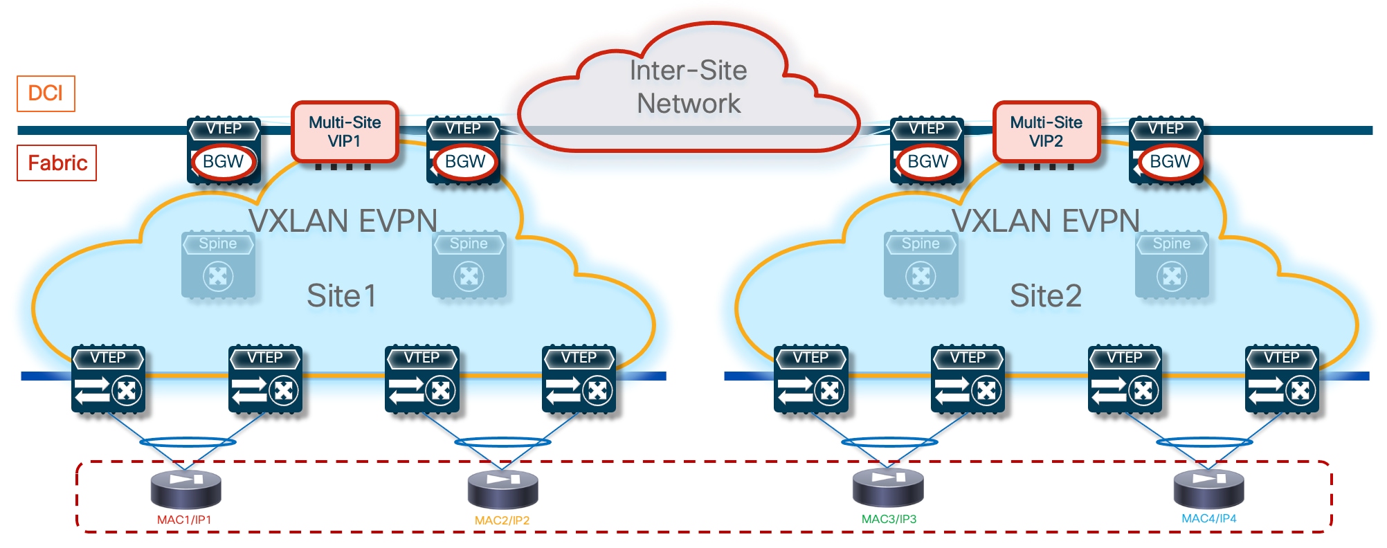
As always, the assumption is that the firewall nodes are deployed as individual Layer 3 devices connected in one-arm mode to a Service Network that is extended across sites. From a physical point of view, each firewall node part of the cluster can be connected to different set of leaf nodes, using a local port-channel or a vPC. Because all the nodes have a unique MAC and IP address, it is not mandatory to force all the nodes in the same site to connect to the same pair of leaf nodes using vPC, as it was the case for the previously discussed Split Spanned Ether-Channel deployment model. The previous figures showed an example where each cluster node is connected to a dedicate pair of leaf nodes using vPC.
From a device on-boarding perspective, the ePBR service definition would list the IP addresses of all the active firewall nodes, part of the same Active/Active firewall cluster. Despite the use of different addresses, this Active/Active cluster represents a single logical firewall service. ePBR load balances the filtered traffic by using a bucket-based load-sharing algorithm using a source or destination IP address.
epbr service FW-Cluster
vrf fw-vrf
service-end-point ip 172.16.1.1 interface Vlan3004
probe icmp frequency 4 retry-down-count 1 retry-up-count 1 timeout 2 source-interface loopback10
reverse ip 172.16.1.1 interface Vlan3004
probe icmp frequency 4 retry-down-count 1 retry-up-count 1 timeout 2 source-interface loopback10
service-end-point ip 172.16.1.2 interface Vlan3004
probe icmp frequency 4 retry-down-count 1 retry-up-count 1 timeout 2 source-interface loopback10
reverse ip 172.16.1.2 interface Vlan3004
probe icmp frequency 4 retry-down-count 1 retry-up-count 1 timeout 2 source-interface loopback10
service-end-point ip 172.16.1.3 interface Vlan3004
probe icmp frequency 4 retry-down-count 1 retry-up-count 1 timeout 2 source-interface loopback10
reverse ip 172.16.1.3 interface Vlan3004
probe icmp frequency 4 retry-down-count 1 retry-up-count 1 timeout 2 source-interface loopback10
service-end-point ip 172.16.1.4 interface Vlan3004
probe icmp frequency 4 retry-down-count 1 retry-up-count 1 timeout 2 source-interface loopback10
reverse ip 172.16.1.4 interface Vlan3004
probe icmp frequency 4 retry-down-count 1 retry-up-count 1 timeout 2 source-interface loopback10
For a specific flow of traffic, ePBR can choose either of the firewalls deployed in both the sites. But stickiness is always maintained for the redirection towards the chosen firewall and symmetry will also be maintained (Figure 79).
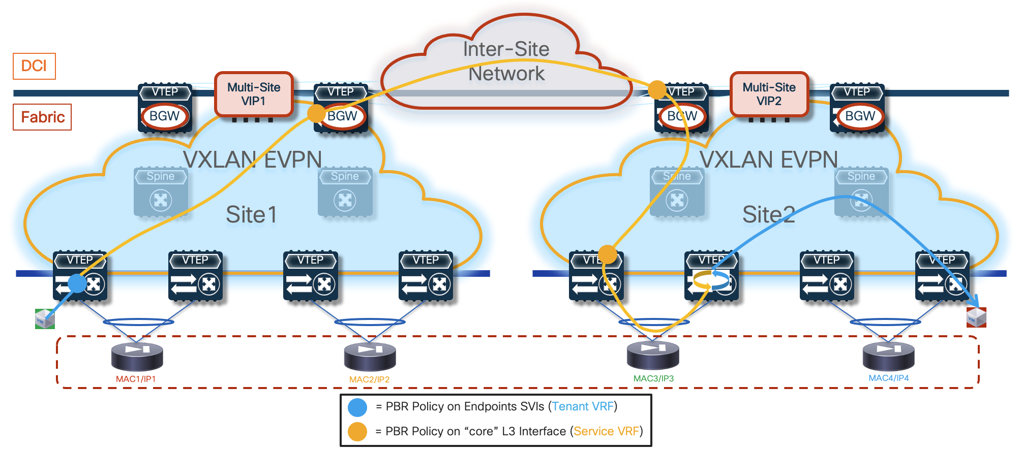
The figure and configuration sample above highlight how the firewall service needs to be onboarded onto a unique service VRF different from the host (tenant) VRFs. Also, routes must be leaked from all the tenant VRFs onto the service VRFs, so that traffic egressing the firewall can be routed towards its actual destination. Route-leaking based on simple export and import must be added to the respective VRF configuration on the service leaf nodes. For more details on the reasons requiring the deployment of separate VRFs, refer to the previous “ePBR and Active/Standby Firewall Cluster Stretched across Sites” section.
It is important to highlight how the load-balancing mechanism implemented by ePBR does not offer any “location awareness” capability, this implies that the firewall cluster nodes selected to handle a specific traffic flow is independent from the location of the source and destination endpoints. This could cause the suboptimal traffic behavior shown in Figure 80, so it is important to consider its impact on the applications deployed in the data center. As a best practice recommendation, this approach should be adopted only when different fabrics are deployed in closed proximity, so to be able to keep the latency low and to provide sufficient bandwidth for communication across fabrics.
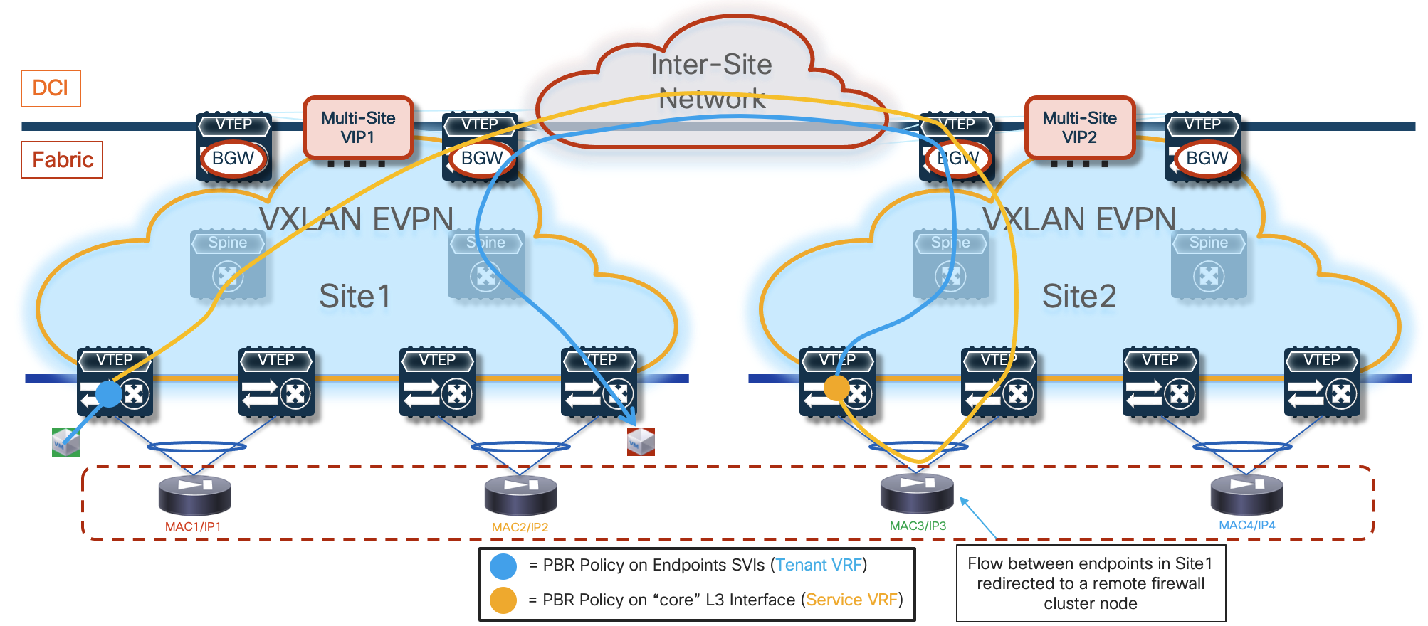
ePBR allows you to monitor the health of the L4-L7 services using advanced probing mechanisms. When a service node in a cluster fails, ePBR fails over the traffic resiliently to other active service nodes leveraging a customized, bucket-based load sharing (based on the considerations made above, this may result in the use of a firewall node located in the same site or in a remote site). Existing flows going to the other active firewall nodes remain unaffected.
Note: The tracking of firewall’s health is performed from the host and service leaf nodes. Leveraging the Layer 2 extension capabilities of VXLAN Multi-Site, the tracking allows leaf nodes in a fabric to verify the good health of an active firewall deployed in a remote fabric (i.e. the probing can successfully work across sites).
The ePBR capability of redirecting both legs of the same traffic flow through the same firewall cluster node is dependent on the configured access-list identifying the flows that need to be redirected. In the specific use case where all the intra-VRF flows should be redirected to the firewall, a “permit any any” access-list should be defined. In that case, ePBR may not be capable of redirecting both legs of the same flow via the same firewall cluster node and it is instead likely that two different nodes will be used. As previously mentioned, for the Cisco ASA implementation an intra-fabric traffic redirection (via CCL) takes care of stitching both legs of the flow via the same firewall node “owning” that flow.
Note: As already discussed for the Active/Standby cluster use case, when defining a “permit any any” access-list to redirect all the traffic flows to the firewall service, it is important to define an access-list to avoid also redirecting the probing traffic. The sample below show the configuration needed when using the ICMP protocol for probing.
ip access-list all-traffic
10 permit ip any any
!
ip access-list exclude-probe
10 permit icmp any any
!
epbr policy t1-pbr
statistics
match ip address exclude-probe exclude
match ip address all-traffic
load-balance method src-ip
10 set service FW-Cluster fail-action drop
Configuration Samples
The samples below capture the relevant configuration on the service leaf nodes, the border gateway node, the compute leaf nodes, and the firewall nodes, in the specific example where the firewall nodes are connected in vPC mode. The reference topology with associated IP addresses is shown in Figure 81.
Note: Similar configuration must be applied to the service leaf nodes connected to the active and standby firewalls. Note that the configuration shown below focuses on the parts that are more relevant for ePBR and does not cover basic VXLAN configuration or endpoints’ subnets definition.
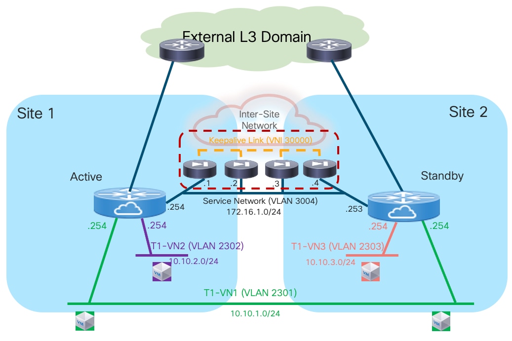
Compute Leaf Nodes
Define the Tenant and the Service VRFs and the loopback interface needed for probing.
vlan 2001
vn-segment 50001
!
vlan 2002
vn-segment 50002
!
vrf context t1-vrf
vni 50001
rd auto
address-family ipv4 unicast
route-target both auto
route-target both auto evpn
address-family ipv6 unicast
route-target both auto
route-target both auto evpn
!
vrf context fw-vrf
vni 50002
rd auto
address-family ipv4 unicast
route-target both auto
route-target both auto evpn
address-family ipv6 unicast
route-target both auto
route-target both auto evpn
!
interface Vlan2001
no shutdown
mtu 9216
vrf member t1-vrf
no ip redirects
ip forward
ipv6 address use-link-local-only
no ipv6 redirects
!
interface Vlan2002
no shutdown
mtu 9216
vrf member fw-vrf
no ip redirects
ip forward
ipv6 address use-link-local-only
no ipv6 redirects
!
interface loopback10
vrf member fw-vrf
ip address 192.168.1.1/32 tag 12345
!
route-map fabric-rmap-redist-subnet permit 10
match tag 12345
!
router bgp 65001
vrf t1-vrf
address-family ipv4 unicast
advertise l2vpn evpn
redistribute direct route-map fabric-rmap-redist-subnet
maximum-paths 4
address-family ipv6 unicast
advertise l2vpn evpn
redistribute direct route-map fabric-rmap-redist-subnet
maximum-paths 4
vrf fw-vrf
address-family ipv4 unicast
advertise l2vpn evpn
redistribute direct route-map fabric-rmap-redist-subnet
maximum-paths 4
address-family ipv6 unicast
advertise l2vpn evpn
redistribute direct route-map fabric-rmap-redist-subnet
maximum-paths 4
!
interface nve1
member vni 50001 associate-vrf
member vni 50002 associate-vrf
Define the L2VNI segments representing the subnets where the endpoints are connected.
vlan 2301
vn-segment 30001
!
vlan 2302
vn-segment 30002
!
interface Vlan2301
no shutdown
vrf member t1-vrf
ip address 10.10.1.254/24 tag 12345
fabric forwarding mode anycast-gateway
!
interface Vlan2302
no shutdown
vrf member t1-vrf
ip address 10.10.2.254/24 tag 12345
fabric forwarding mode anycast-gateway
!
interface nve1
member vni 30001
mcast-group 239.1.1.1
member vni 30002
mcast-group 239.1.1.1
!
evpn
vni 30001 l2
rd auto
route-target import auto
route-target export auto
vni 30002 l2
rd auto
route-target import auto
route-target export auto
!
interface port-channel1
description vPC to the ESXi host
switchport mode trunk
switchport trunk allowed vlan 2301-2302
spanning-tree port type edge trunk
spanning-tree bpduguard enable
mtu 9216
vpc 1
Define the required ePBR policies and apply them to the endpoints’ SVIs.
Feature pbr
feature sla sender
feature epbr
!
ip access-list t1-acl
10 permit ip 10.10.1.0/24 10.10.2.0/24
!
epbr service FW-Cluster
vrf fw-vrf
service-end-point ip 172.16.1.1
probe icmp frequency 4 retry-down-count 1 retry-up-count 1 timeout 2 source-interface loopback10
reverse ip 172.16.1.1
probe icmp frequency 4 retry-down-count 1 retry-up-count 1 timeout 2 source-interface loopback10
service-end-point ip 172.16.1.2
probe icmp frequency 4 retry-down-count 1 retry-up-count 1 timeout 2 source-interface loopback10
reverse ip 172.16.1.2
probe icmp frequency 4 retry-down-count 1 retry-up-count 1 timeout 2 source-interface loopback10
service-end-point ip 172.16.1.3
probe icmp frequency 4 retry-down-count 1 retry-up-count 1 timeout 2 source-interface loopback10
reverse ip 172.16.1.3
probe icmp frequency 4 retry-down-count 1 retry-up-count 1 timeout 2 source-interface loopback10
service-end-point ip 172.16.1.4
probe icmp frequency 4 retry-down-count 1 retry-up-count 1 timeout 2 source-interface loopback10
reverse ip 172.16.1.4
probe icmp frequency 4 retry-down-count 1 retry-up-count 1 timeout 2 source-interface loopback10
!
epbr policy t1-pbr
statistics
match ip address t1-acl
load-balance method src-ip
10 set service FW-Cluster fail-action drop
!
interface Vlan2301
epbr ip policy t1-pbr
epbr ip policy t1-pbr reverse
interface Vlan2302
epbr ip policy t1-pbr
epbr ip policy t1-pbr reverse
Service Leaf Nodes
Define the Tenant and the Service VRFs and the loopback interface needed for probing. Specific configuration is also required to ensure that the endpoints’ subnet in the Tenant VRF (t1-vrf) can be leaked to the Service VRF (fw-vrf).
vlan 2001
vn-segment 50001
!
vlan 2002
vn-segment 50002
!
vrf context t1-vrf
vni 50001
rd auto
address-family ipv4 unicast
route-target both auto
route-target both auto evpn
address-family ipv6 unicast
route-target both auto
route-target both auto evpn
!
vrf context fw-vrf
vni 50002
rd auto
address-family ipv4 unicast
route-target both auto
route-target both auto evpn
route-target import 65001:50001
route-target import 65001:50001 evpn
address-family ipv6 unicast
route-target both auto
route-target both auto evpn
!
interface Vlan2001
no shutdown
mtu 9216
vrf member t1-vrf
no ip redirects
ip forward
ipv6 address use-link-local-only
no ipv6 redirects
!
interface Vlan2002
no shutdown
mtu 9216
vrf member fw-vrf
no ip redirects
ip forward
ipv6 address use-link-local-only
no ipv6 redirects
!
interface loopback10
vrf member fw-vrf
ip address 192.168.1.2/32 tag 12345
!
route-map fabric-rmap-redist-subnet permit 10
match tag 12345
!
router bgp 65001
vrf t1-vrf
address-family ipv4 unicast
advertise l2vpn evpn
redistribute direct route-map fabric-rmap-redist-subnet
maximum-paths 4
address-family ipv6 unicast
advertise l2vpn evpn
redistribute direct route-map fabric-rmap-redist-subnet
maximum-paths 4
vrf fw-vrf
address-family ipv4 unicast
advertise l2vpn evpn
redistribute direct route-map fabric-rmap-redist-subnet
maximum-paths 4
address-family ipv6 unicast
advertise l2vpn evpn
redistribute direct route-map fabric-rmap-redist-subnet
maximum-paths 4
!
interface nve1
member vni 50001 associate-vrf
member vni 50002 associate-vrf
Define the L2VNI segment used as firewall Keepalive Link (vn-segment 30000, Layer-2 only) and the Service Network to connect to the firewall node.
vlan 2300
vn-segment 30000
!
vlan 3004
vn-segment 30004
!
interface Vlan3004
no shutdown
vrf member t1-vrf
ip address 172.16.1.254/24 tag 12345
fabric forwarding mode anycast-gateway
!
interface nve1
member vni 30000
mcast-group 239.1.1.1
member vni 30004
mcast-group 239.1.1.1
!
evpn
vni 30000 l2
rd auto
route-target import auto
route-target export auto
vni 30004 l2
rd auto
route-target import auto
route-target export auto
!
interface port-channel
description vPC to the Firewall Node
switchport mode trunk
switchport trunk allowed vlan 2300,3004
Define the required ePBR policies and apply them to the “core” Layer 3 interface.
feature pbr
feature sla sender
feature epbr
!
ip access-list t1-acl
10 permit ip 10.10.1.0/24 10.10.2.0/24
!
epbr service FW-Cluster
vrf fw-vrf
service-end-point ip 172.16.1.1 interface Vlan3004
probe icmp frequency 4 retry-down-count 1 retry-up-count 1 timeout 2 source-interface loopback10
reverse ip 172.16.1.1 interface Vlan3004
probe icmp frequency 4 retry-down-count 1 retry-up-count 1 timeout 2 source-interface loopback10
service-end-point ip 172.16.1.2 interface Vlan3004
probe icmp frequency 4 retry-down-count 1 retry-up-count 1 timeout 2 source-interface loopback10
reverse ip 172.16.1.2 interface Vlan3004
probe icmp frequency 4 retry-down-count 1 retry-up-count 1 timeout 2 source-interface loopback10
service-end-point ip 172.16.1.3 interface Vlan3004
probe icmp frequency 4 retry-down-count 1 retry-up-count 1 timeout 2 source-interface loopback10
reverse ip 172.16.1.3 interface Vlan3004
probe icmp frequency 4 retry-down-count 1 retry-up-count 1 timeout 2 source-interface loopback10
service-end-point ip 172.16.1.4 interface Vlan3004
probe icmp frequency 4 retry-down-count 1 retry-up-count 1 timeout 2 source-interface loopback10
reverse ip 172.16.1.4 interface Vlan3004
probe icmp frequency 4 retry-down-count 1 retry-up-count 1 timeout 2 source-interface loopback10
!
epbr policy t1-pbr
statistics
match ip address t1-acl
load-balance method src-ip
10 set service FW-Cluster fail-action drop
!
interface Vlan2002
no shutdown
mtu 9216
vrf member fw-vrf
no ip redirects
ip forward
ipv6 address use-link-local-only
epbr ip policy t1-pbr
epbr ip policy t1-pbr reverse
BGW Nodes
Define the Tenant and the Service VRFs that need to be stretched across sites and the loopback interface needed for probing. Specific configuration is also required to ensure that the endpoints’ subnet in the Tenant VRF (t1-vrf) can be leaked to the Service VRF (fw-vrf).
vlan 2001
vn-segment 50001
!
vlan 2002
vn-segment 50002
!
vrf context t1-vrf
vni 50001
rd auto
address-family ipv4 unicast
route-target both auto
route-target both auto evpn
address-family ipv6 unicast
route-target both auto
route-target both auto evpn
!
vrf context fw-vrf
vni 50002
rd auto
address-family ipv4 unicast
route-target both auto
route-target both auto evpn
address-family ipv6 unicast
route-target both auto
route-target both auto evpn
!
interface Vlan2001
no shutdown
mtu 9216
vrf member t1-vrf
no ip redirects
ip forward
ipv6 address use-link-local-only
no ipv6 redirects
!
interface Vlan2002
no shutdown
mtu 9216
vrf member fw-vrf
no ip redirects
ip forward
ipv6 address use-link-local-only
no ipv6 redirects
!
interface loopback10
vrf member fw-vrf
ip address 192.168.1.2/32 tag 12345
!
route-map fabric-rmap-redist-subnet permit 10
match tag 12345
!
router bgp 65001
vrf t1-vrf
address-family ipv4 unicast
advertise l2vpn evpn
redistribute direct route-map fabric-rmap-redist-subnet
maximum-paths 4
address-family ipv6 unicast
advertise l2vpn evpn
redistribute direct route-map fabric-rmap-redist-subnet
maximum-paths 4
vrf fw-vrf
address-family ipv4 unicast
advertise l2vpn evpn
redistribute direct route-map fabric-rmap-redist-subnet
maximum-paths 4
address-family ipv6 unicast
advertise l2vpn evpn
redistribute direct route-map fabric-rmap-redist-subnet
maximum-paths 4
!
interface nve1
member vni 50001 associate-vrf
member vni 50002 associate-vrf
Define the L2VNIs that need to be stretched across sites.
vlan 2300
vn-segment 30000
!
vlan 2301
vn-segment 30001
!
vlan 3004
vn-segment 30004
!
interface nve1
member vni 30000
mcast-group 239.1.1.1
member vni 30001
mcast-group 239.1.1.1
member vni 30004
mcast-group 239.1.1.1
!
evpn
vni 30000 l2
rd auto
route-target import auto
route-target export auto
vni 30001 l2
rd auto
route-target import auto
route-target export auto
vni 30004 l2
rd auto
route-target import auto
route-target export auto
Define the required ePBR policies and apply them to the “core” Layer 3 interface.
feature pbr
feature sla sender
feature epbr
!
ip access-list t1-acl
10 permit ip 10.10.1.0/24 10.10.2.0/24
!
epbr service FW-Cluster
vrf fw-vrf
service-end-point ip 172.16.1.1
probe icmp frequency 4 retry-down-count 1 retry-up-count 1 timeout 2 source-interface loopback10
reverse ip 172.16.1.1
probe icmp frequency 4 retry-down-count 1 retry-up-count 1 timeout 2 source-interface loopback10
service-end-point ip 172.16.1.2
probe icmp frequency 4 retry-down-count 1 retry-up-count 1 timeout 2 source-interface loopback10
reverse ip 172.16.1.2
probe icmp frequency 4 retry-down-count 1 retry-up-count 1 timeout 2 source-interface loopback10
service-end-point ip 172.16.1.3
probe icmp frequency 4 retry-down-count 1 retry-up-count 1 timeout 2 source-interface loopback10
reverse ip 172.16.1.3
probe icmp frequency 4 retry-down-count 1 retry-up-count 1 timeout 2 source-interface loopback10
service-end-point ip 172.16.1.4
probe icmp frequency 4 retry-down-count 1 retry-up-count 1 timeout 2 source-interface loopback10
reverse ip 172.16.1.4
probe icmp frequency 4 retry-down-count 1 retry-up-count 1 timeout 2 source-interface loopback10
!
epbr policy t1-pbr
statistics
match ip address t1-acl
load-balance method src-ip
10 set service FW fail-action drop
!
interface Vlan2002
no shutdown
mtu 9216
vrf member fw-vrf
no ip redirects
ip forward
ipv6 address use-link-local-only
epbr ip policy t1-pbr
epbr ip policy t1-pbr reverse
Firewall Nodes
The configuration sample below is taken from a Cisco ASA model. This configuration can be easily adapted to apply to different types of firewall devices (physical or virtual form factors). Also, the assumption is that the required failover configuration has already been applied to build an Active/Active cluster in Individual Interface Mode, as described in the previous “Individual Interface Active/Active Cluster Mode” section.
The configuration of the firewall nodes for this use case is quite straightforward, as there is no requirement to enable any control plane protocol and a single interface is needed to connect the firewall to the Service Network (one-arm model). A simple default route is used to send the traffic back to the fabric. The “same-security-traffic permit intra-interface” command is required to allow reception and transmission of traffic using the same one-arm interface.
Note: The configuration is performed on the cluster control node and automatically synchronized to all the data nodes part of the cluster. Notice how a specific IP address (172.16.1.5) must be assigned to the one-arm interface, representing a “virtual IP address” for the cluster. However, traffic redirection is always performed to the unique IP addresses assigned to each node (172.16.1.1-172.16.1.4), as listed in the ePBR policy defined on the fabric nodes.
ip local pool one-arm 172.16.1.1-172.16.1.4 mask 255.255.255.0
!
interface Port-channel2.3004
vlan 3004
nameif one-arm
security-level 100
ip address 172.16.1.5 255.255.255.0 cluster-pool one-arm
!
same-security-traffic permit intra-interface
!
access-list permit-any extended permit ip any any
access-group permit-any in interface one-arm
!
route one-arm 0.0.0.0 0.0.0.0 172.16.1.254 1
Configuration Verification
Below are some relevant CLI commands that can be used to verify that the applied ePBR configuration is working properly.
show ip access-lists dynamic
This command displays the access-lists that are created to match the traffic for both the directions of the flow (as previously show, the ACL that is configured can instead only specify one specific direction).
Fabric-1-Leaf-1# show access-lists dynamic
IP access list epbr_t1-pbr_1_fwd_bucket_1
10 permit ip 10.10.1.0 0.0.0.252 10.10.2.0 0.0.0.255
IP access list epbr_t1-pbr_1_fwd_bucket_2
10 permit ip 10.10.1.1 0.0.0.252 10.10.2.0 0.0.0.255
IP access list epbr_t1-pbr_1_fwd_bucket_3
10 permit ip 10.10.1.2 0.0.0.252 10.10.2.0 0.0.0.255
IP access list epbr_t1-pbr_1_fwd_bucket_4
10 permit ip 10.10.1.3 0.0.0.252 10.10.2.0 0.0.0.255
IP access list epbr_t1-pbr_1_rev_bucket_1
10 permit ip 10.10.2.0 0.0.0.255 10.10.1.0 0.0.0.252
IP access list epbr_t1-pbr_1_rev_bucket_2
10 permit ip 10.10.2.0 0.0.0.255 10.10.1.1 0.0.0.252
IP access list epbr_t1-pbr_1_rev_bucket_3
10 permit ip 10.10.2.0 0.0.0.255 10.10.1.2 0.0.0.252
IP access list epbr_t1-pbr_1_rev_bucket_4
10 permit ip 10.10.2.0 0.0.0.255 10.10.1.3 0.0.0.252
Notice how four buckets are created for the forward directions (i.e. 10.10.1.0/24 to 10.10.2.0/24) and four different buckets are created for the reverse direction (i.e. 10.10.2.0/24 to 10.10.1.0/24). Depending on the specific IP addresses of the communicating endpoints, one specific bucket will be selected for the forward direction. In case of a specific access-list, as the one shown in this example, the same bucket would then be used for the reverse flow.
Traffic flows be associated to one of the four buckets based on the match between the endpoint’s IP address and the access-list dynamically associated to each bucket: representing the last digit of the IP address in binary form (8 bits), the association to each bucket depends on the value of the last two bits:
● xxxxxx00 gets associated to bucket 1
● xxxxxx01 gets associated to bucket 2
● xxxxxx10 gets associated to bucket 3
● xxxxxx11s get associated to bucket 4
Let’s consider the example of endpoint 10.10.1.1 communicating with 10.10.2.2: by looking at the definition of the access-list, results clear the association of both legs of the flow to the same bucket 2, because the “1” last digit of 10.10.1.1 is represented in binary form as “00000001”.
show route-map dynamic
This command displays the route-map that are dynamically created on the compute leaf nodes, service leaf nodes or BGW nodes.
For example, on a compute node, where the ePBR policy is only applied to the endpoint subnet (VLAN 2301), the output shows how the lookup for steering the traffic toward the active firewall is forced to be performed in the Service VRF via the definition of “set-vrf” clauses. Also, all four service nodes are associated to each bucket (in the forwarding and reverse directions). The leaf node tracks the status of those nodes and if the first in the list were to go down, the redirection would start steering the traffic toward the second node. That is, a failure of a firewall node does not cause a change of the selected bucket (as that solely depends on the IP address of the endpoints), but only of the nodes used as part of the bucket.
Fabric-1-Leaf-1# show route-map dynamic
route-map epbr_rmap_v4_Vlan2301, permit, sequence 13401
Match clauses:
ip address (access-lists): epbr_t1-pbr_1_fwd_bucket_1
Set clauses:
ip vrf fw-vrf next-hop verify-availability 172.16.1.1 track 1 [ UP ]
ip vrf fw-vrf next-hop verify-availability 172.16.1.4 track 4 [ UP ]
ip vrf fw-vrf next-hop verify-availability 172.16.1.3 track 3 [ UP ]
ip vrf fw-vrf next-hop verify-availability 172.16.1.2 track 2 [ UP ] force-order drop-on-fail
route-map epbr_rmap_v4_Vlan2301, permit, sequence 13402
Match clauses:
ip address (access-lists): epbr_t1-pbr_1_fwd_bucket_2
Set clauses:
ip vrf fw-vrf next-hop verify-availability 172.16.1.2 track 2 [ UP ]
ip vrf fw-vrf next-hop verify-availability 172.16.1.3 track 3 [ UP ]
ip vrf fw-vrf next-hop verify-availability 172.16.1.4 track 4 [ UP ]
ip vrf fw-vrf next-hop verify-availability 172.16.1.1 track 1 [ UP ] force-order drop-on-fail
route-map epbr_rmap_v4_Vlan2301, permit, sequence 13403
Match clauses:
ip address (access-lists): epbr_t1-pbr_1_fwd_bucket_3
Set clauses:
ip vrf fw-vrf next-hop verify-availability 172.16.1.3 track 3 [ UP ]
ip vrf fw-vrf next-hop verify-availability 172.16.1.2 track 2 [ UP ]
ip vrf fw-vrf next-hop verify-availability 172.16.11 track 1 [ UP ]
ip vrf fw-vrf next-hop verify-availability 172.16.1.14 track 4 [ UP ] force-order drop-on-fail
route-map epbr_rmap_v4_Vlan2301, permit, sequence 13404
Match clauses:
ip address (access-lists): epbr_t1-pbr_1_fwd_bucket_4
Set clauses:
ip vrf fw-vrf next-hop verify-availability 172.16.1.4 track 4 [ UP ]
ip vrf fw-vrf next-hop verify-availability 172.16.1.1 track 1 [ UP ]
ip vrf fw-vrf next-hop verify-availability 172.16.1.2 track 2 [ UP ]
ip vrf fw-vrf next-hop verify-availability 172.16.1.3 track 3 [ UP ] force-order drop-on-fail
route-map epbr_rmap_v4_Vlan2301, permit, sequence 13751
Match clauses:
ip address (access-lists): epbr_t1-pbr_1_rev_bucket_1
Set clauses:
ip vrf fw-vrf next-hop verify-availability 172.16.1.1 track 5 [ UP ]
ip vrf fw-vrf next-hop verify-availability 172.16.1.4 track 8 [ UP ]
ip vrf fw-vrf next-hop verify-availability 172.16.1.3 track 7 [ UP ]
ip vrf fw-vrf next-hop verify-availability 172.16.1.2 track 6 [ UP ] force-order drop-on-fail
route-map epbr_rmap_v4_Vlan2301, permit, sequence 13752
Match clauses:
ip address (access-lists): epbr_t1-pbr_1_rev_bucket_2
Set clauses:
ip vrf fw-vrf next-hop verify-availability 172.16.1.2 track 6 [ UP ]
ip vrf fw-vrf next-hop verify-availability 172.16.1.3 track 7 [ UP ]
ip vrf fw-vrf next-hop verify-availability 172.16.1.4 track 8 [ UP ]
ip vrf fw-vrf next-hop verify-availability 172.16.1.1 track 5 [ UP ] force-order drop-on-fail
route-map epbr_rmap_v4_Vlan2301, permit, sequence 13753
Match clauses:
ip address (access-lists): epbr_t1-pbr_1_rev_bucket_3
Set clauses:
ip vrf fw-vrf next-hop verify-availability 172.16.1.3 track 7 [ UP ]
ip vrf fw-vrf next-hop verify-availability 172.16.1.2 track 6 [ UP ]
ip vrf fw-vrf next-hop verify-availability 172.16.1.1 track 5 [ UP ]
ip vrf fw-vrf next-hop verify-availability 172.16.1.4 track 8 [ UP ] force-order drop-on-fail
route-map epbr_rmap_v4_Vlan2301, permit, sequence 13754
Match clauses:
ip address (access-lists): epbr_ t1-pbr_1_rev_bucket_4
Set clauses:
ip vrf fw-vrf next-hop verify-availability 172.16.1.4 track 8 [ UP ]
ip vrf fw-vrf next-hop verify-availability 172.16.1.1 track 5 [ UP ]
ip vrf fw-vrf next-hop verify-availability 172.16.1.2 track 6 [ UP ]
ip vrf fw-vrf next-hop verify-availability 172.16.1.3 track 7 [ UP ] force-order drop-on-fail
The same command issued on a service leaf node or on a BGW node shows similar information, now relative to the “core” Layer 3 interface (VLAN 2002).
Fabric-1-Leaf-3# show route-map dynamic
route-map epbr_rmap_v4_Vlan2002, permit, sequence 13401
Match clauses:
ip address (access-lists): epbr_t1-pbr_1_fwd_bucket_1
Set clauses:
ip vrf fw-vrf next-hop verify-availability 172.16.1.1 track 1 [ UP ]
ip vrf fw-vrf next-hop verify-availability 172.16.1.4 track 4 [ UP ]
ip vrf fw-vrf next-hop verify-availability 172.16.1.3 track 3 [ UP ]
ip vrf fw-vrf next-hop verify-availability 172.16.1.2 track 2 [ UP ] force-order
route-map epbr_rmap_v4_Vlan2002, permit, sequence 13402
Match clauses:
ip address (access-lists): epbr_t1-pbr_1_fwd_bucket_2
Set clauses:
ip vrf fw-vrf next-hop verify-availability 172.16.1.2 track 2 [ UP ]
ip vrf fw-vrf next-hop verify-availability 172.16.1.3 track 3 [ UP ]
ip vrf fw-vrf next-hop verify-availability 172.16.1.4 track 4 [ UP ]
ip vrf fw-vrf next-hop verify-availability 172.16.1.1 track 1 [ UP ] force-order
route-map epbr_rmap_v4_Vlan2002, permit, sequence 13403
Match clauses:
ip address (access-lists): epbr_t1-pbr_1_fwd_bucket_3
Set clauses:
ip vrf fw-vrf next-hop verify-availability 172.16.1.3 track 3 [ UP ]
ip vrf fw-vrf next-hop verify-availability 172.16.1.2 track 2 [ UP ]
ip vrf fw-vrf next-hop verify-availability 172.16.1.1 track 1 [ UP ]
ip vrf fw-vrf next-hop verify-availability 172.16.1.4 track 4 [ UP ] force-order
route-map epbr_rmap_v4_Vlan2002, permit, sequence 13404
Match clauses:
ip address (access-lists): epbr_t1-pbr_1_fwd_bucket_4
Set clauses:
ip vrf fw-vrf next-hop verify-availability 172.16.1.4 track 4 [ UP ]
ip vrf fw-vrf next-hop verify-availability 172.16.1.1 track 1 [ UP ]
ip vrf fw-vrf next-hop verify-availability 172.16.1.2 track 2 [ UP ]
ip vrf fw-vrf next-hop verify-availability 172.16.1.3 track 3 [ UP ] force-order
route-map epbr_rmap_v4_Vlan2002, permit, sequence 13751
Match clauses:
ip address (access-lists): epbr_t1-pbr_1_rev_bucket_1
Set clauses:
ip vrf fw-vrf next-hop verify-availability 172.16.1.11 track 5 [ UP ]
ip vrf fw-vrf next-hop verify-availability 172.16.1.14 track 8 [ UP ]
ip vrf fw-vrf next-hop verify-availability 172.16.1.13 track 7 [ UP ]
ip vrf fw-vrf next-hop verify-availability 172.16.1.12 track 6 [ UP ] force-order
route-map epbr_rmap_v4_Vlan2002, permit, sequence 13752
Match clauses:
ip address (access-lists): epbr_t1-pbr_1_rev_bucket_2
Set clauses:
ip vrf fw-vrf next-hop verify-availability 172.16.1.12 track 6 [ UP ]
ip vrf fw-vrf next-hop verify-availability 172.16.1.13 track 7 [ UP ]
ip vrf fw-vrf next-hop verify-availability 172.16.1.14 track 8 [ UP ]
ip vrf fw-vrf next-hop verify-availability 172.16.1.11 track 5 [ UP ] force-order
route-map epbr_rmap_v4_Vlan2002, permit, sequence 13753
Match clauses:
ip address (access-lists): epbr_t1-pbr_1_rev_bucket_3
Set clauses:
ip vrf fw-vrf next-hop verify-availability 172.16.1.13 track 7 [ UP ]
ip vrf fw-vrf next-hop verify-availability 172.16.1.12 track 6 [ UP ]
ip vrf fw-vrf next-hop verify-availability 172.16.1.11 track 5 [ UP ]
ip vrf fw-vrf next-hop verify-availability 172.16.1.14 track 8 [ UP ] force-order
route-map epbr_rmap_v4_Vlan2002, permit, sequence 13754
Match clauses:
ip address (access-lists): epbr_t1-pbr_1_rev_bucket_4
Set clauses:
ip vrf fw-vrf next-hop verify-availability 172.16.1.14 track 8 [ UP ]
ip vrf fw-vrf next-hop verify-availability 172.16.1.11 track 5 [ UP ]
ip vrf fw-vrf next-hop verify-availability 172.16.1.12 track 6 [ UP ]
ip vrf fw-vrf next-hop verify-availability 172.16.1.13 track 7 [ UP ] force-order
show epbr policy <policy_name>
This command allows to display specific ePBR policy information, including the health status for the service node. The health status must be shown as “UP” for the ePBR policy to actively redirect traffic to such service.
Fabric-1-Leaf-1# show epbr policy t1-pbr
Policy-map : t1-pbr
Match clause:
ip address (access-lists): t1-acl
action:Redirect
service FW-Cluster, sequence 10, fail-action Drop
IP 172.16.1.1 track 1 [UP]
IP 172.16.1.2 track 2 [UP]
IP 172.16.1.3 track 3 [UP]
IP 172.16.1.4 track 4 [UP]
Policy Interfaces:
Vlan2301
show epbr statistics policy <policy_name> [reverse]
The output of this command allows to verify that the traffic is being redirected to the defined firewall node. The counter must increase when traffic is flowing and “Redirect” must be show next to the counter. The direction of the traffic redirected is the one that specifically matches the configured ACL: in our specific example, “t1-acl” specified traffic from subnet 10.10.1.0/24 to 10.10.2.0/24 and using the same endpoint of the example above, we can notice how traffic is using bucket 2.
Fabric-1-Leaf-1# show epbr statistics policy t1-pbr
Policy-map t1-pbr, match t1-acl
Bucket count: 4
traffic match : bucket 1
FW-Cluster : 0 (N/A)
traffic match : bucket 2
FW-Cluster : 22 (Redirect)
traffic match : bucket 3
FW-Cluster : 0 (N/A)
traffic match : bucket 4
FW-Cluster : 0 (N/A)
Note: At the time of writing of this document (up to NX-OS release 10.4(1)), the counter shown in the example above increases only on the compute leaf nodes, where the ePBR policy is applied on the endpoint subnet. The output for service leaf and BGW nodes (where the policy is applied on the “core” L3 interface) shown “0” instead, this problem will be fixed in a future NX-OS release.
The “reverse” option for the command should be used to verify redirection of traffic flows in the opposite direction of what specified in the access-list. Below is the output of the command (with and without the “reverse” option) issued on a compute leaf where only the subnet 10.10.2.0/24 is deployed, in our specific example where the ACL matches traffic between 10.10.1.1/24 and 10.10.2.2/24.
Fabric-2-Leaf-4# show epbr statistics policy t1-pbr
Policy-map ti=pbr, match t1-acl
Bucket count: 4
traffic match : bucket 1
FW-Cluster : 0 (N/A)
traffic match : bucket 2
FW-Cluster : 0 (N/A)
traffic match : bucket 3
FW-Cluster : 0 (N/A)
traffic match : bucket 4
FW-Cluster : 0 (N/A)
Fabric-2-Leaf-4# show epbr stat policy max-pbr-cluster reverse
Policy-map max-pbr-cluster, match max-acl
Bucket count: 4
traffic match : bucket 1
FW-Cluster : 0 (N/A)
traffic match : bucket 2
FW-Cluster : 215 (Redirect)
traffic match : bucket 3
FW-Cluster : 0 (N/A)
traffic match : bucket 4
FW-Cluster : 0 (N/A)
As expected, the counter shows “0” in the “direct” direction, as the ePBR policy on this leaf node is only applied to return flows between endpoints 10.10.2.2/24 and 10.10.1.1/24 and it is associated to the same bucket 2 used in the forward direction.
The integration of service devices (firewall, load balancers, etc.) into a single VXLAN EVPN fabric or into a VXLAN EVPN multi-fabric design (VXLAN Multi-Site) can be achieved in multiple ways. This paper focused on the specific scenarios of the insertion of a firewall service in a multi-fabric architecture to enforce security policies for both East-West and North-South communication flows.
Before choosing a specific service function deployment model, it is important to make some important design choices:
● The redundancy model for the firewall service being deployed
The paper covered the three main options represented by a two-nodes Active/Standby cluster, a multi-nodes Active/Active cluster, and the use of multiple independent nodes.
● The connectivity of the service nodes implementing the specific service function
To increase the resiliency of the service function, we discussed how to distribute the service nodes across the different fabrics that are part of the same VXLAN Multi-Site domain.
● The specific role of the service device, which can be used to enforce security policies intra-tenant or inter-tenant.
Note: all the deployment models discussed in this paper leverage firewall devices configured in routed mode, as it is the most common use case found nowadays in production networks (versus a more traditional use of firewall devices in transparent mode).
Once the service function has been defined, one of the possible deployment options discussed in this paper can be implemented to insert it into the architecture. Some approaches leverage traditional routing techniques to redirect traffic to the service devices and avoid creation of asymmetric traffic paths, but the paper also focused on the use of the Policy-Based Redirection (PBR) functionality. The use of PBR represents a more intelligent way of performimng service chaining to steer traffic flows through service devices and supports the deployment of service device clusters across sites (either in a more traditional Active/Standby configuration or even in Active/Active mode).