PDF(7.1 MB) View with Adobe Reader on a variety of devices
Updated:December 1, 2025
Bias-Free Language
The documentation set for this product strives to use bias-free language. For the purposes of this documentation set, bias-free is defined as language that does not imply discrimination based on age, disability, gender, racial identity, ethnic identity, sexual orientation, socioeconomic status, and intersectionality. Exceptions may be present in the documentation due to language that is hardcoded in the user interfaces of the product software, language used based on RFP documentation, or language that is used by a referenced third-party product. Learn more about how Cisco is using Inclusive Language.
First Published: December 21, 2021
Deploy a Cluster for ASA on the Secure Firewall 3100/4200/6100
Clustering lets you group multiple ASAs together as a single
logical device. A cluster provides all the convenience of a single device
(management, integration into a network) while achieving the increased
throughput and redundancy of multiple devices.
This section describes the clustering architecture and how it works.
How the Cluster Fits into Your Network
The cluster consists of multiple firewalls acting as a single unit. To act
as a cluster, the firewalls need the following infrastructure:
Isolated, high-speed backplane network for intra-cluster communication, known as the cluster control link.
Management access to each firewall for configuration and monitoring.
When you place the cluster in your network, the upstream and downstream
routers need to be able to load-balance the data coming to and from the cluster using
one of the following
methods:
Spanned EtherChannel (Recommended)—Interfaces on multiple
members of the cluster are grouped into a single EtherChannel; the EtherChannel
performs load balancing between units.
Policy-Based Routing (Routed firewall mode only)—The
upstream and downstream routers perform load balancing between units using route
maps and ACLs.
Equal-Cost Multi-Path Routing (Routed firewall mode
only)—The upstream and downstream routers perform load balancing between units
using equal cost static or dynamic routes.
Cluster Members
Cluster members work together to accomplish the sharing of the security policy and traffic flows. This section describes the
nature of each member role.
Bootstrap
Configuration
On each device, you configure a minimal bootstrap configuration
including the cluster name, cluster control link interface, and other cluster settings.
The first node on which you enable clustering typically becomes the control node. When you enable clustering on subsequent
nodes, they join the cluster as data nodes.
Control and Data Node Roles
One member of the cluster
is the control node. If multiple cluster nodes come online at the same time, the control node
is determined by the priority setting in the bootstrap
configuration; the priority is set between 1 and 100, where 1 is the highest priority.
All other members are data nodes. Typically, when you first create a
cluster, the first node you add becomes the control node simply because it is the only node
in the cluster so far.
You
must perform all configuration (aside from the bootstrap configuration) on the control node
only; the configuration is then replicated to the data nodes. In the case of physical assets,
such as interfaces, the configuration of the control node is mirrored on all data nodes. For
example, if you configure Ethernet 1/2 as the inside interface and Ethernet 1/1 as the outside
interface, then these interfaces are also used on the data nodes as inside and outside
interfaces.
Some features do not scale
in a cluster, and the control node handles all traffic for those features.
Cluster Interfaces
You can configure data interfaces as
either
Spanned EtherChannels or as
Individual interfaces. All data interfaces in the cluster must be
one type only. See About Cluster Interfaces for more information.
Cluster Control Link
Each unit must dedicate at least one hardware interface as the cluster control link. See Cluster Control Link for more information.
Configuration
Replication
All nodes in the cluster share a single configuration. You can only make
configuration changes on the control node (with the exception of the bootstrap
configuration), and changes are automatically synced to all other nodes in the
cluster.
ASA Cluster Management
One of the benefits of using ASA clustering is the ease of management. This section describes how to manage the cluster.
Management Network
We recommend connecting all units to a single management network. This network is separate from the cluster control link.
Management
Interface
For the management interface, we recommend using one of the
dedicated management interfaces. You can configure the management interfaces as
Individual interfaces (for both routed and transparent modes) or as a Spanned
EtherChannel interface.
We recommend using Individual interfaces for management. Individual interfaces let you
connect directly to each unit if necessary, while a Spanned EtherChannel interface only
allows remote connection to the current control unit.
Note
If you use Spanned EtherChannel interface mode and configure
the management interface as an Individual interface, you cannot enable dynamic
routing for the management interface. You must use a static route.
For an Individual interface, the Main cluster IP address is a fixed address
for the cluster that always belongs to the current control unit. For each interface, you
also configure a range of addresses so that each unit, including the current control
unit, can use a Local address from the range. The Main cluster IP address provides
consistent management access to an address; when a control unit changes, the Main
cluster IP address moves to the new control unit, so management of the cluster continues
seamlessly. The Local IP address is used for routing, and is also useful for
troubleshooting.
For example, you can manage the cluster by connecting to the Main cluster
IP address, which is always attached to the current control unit. To manage an
individual member, you can connect to the Local IP address.
Note
To-the-box traffic needs to be directed to the node's management IP address;
to-the-box traffic is not forwarded over the cluster control link to any other
node.
For outbound management traffic such as TFTP or syslog, each unit,
including the control unit, uses the Local IP address to connect to the server.
For a Spanned EtherChannel interface, you can only configure one IP
address, and that IP address is always attached to the control unit. You cannot connect
directly to a data unit using the EtherChannel interface; we recommend configuring the
management interface as an Individual interface so that you can connect to each unit.
Note that you can use a device-local EtherChannel for management.
Control Unit Management Vs. Data Unit Management
All management and monitoring can take place on the control node. From
the control node, you can check runtime statistics, resource usage, or other
monitoring information of all nodes. You can also issue a command to all nodes
in the cluster, and replicate the console messages from data nodes to the
control node.
You can monitor data nodes directly if desired. Although also available
from the control node, you can perform file management on data nodes (including
backing up the configuration and updating images). The following functions are
not available from the control node:
Monitoring per-node cluster-specific statistics.
Syslog monitoring per node (except for syslogs sent to the console when
console replication is enabled).
SNMP
NetFlow
Crypto Key Replication
When you create a crypto key on the control node, the key is replicated
to all data nodes. If you have an SSH session to the Main cluster IP address,
you will be disconnected if the control node fails. The new control node uses
the same key for SSH connections, so that you do not need to update the cached
SSH host key when you reconnect to the new control node.
ASDM Connection
Certificate IP Address Mismatch
By default, a self-signed certificate is used for the ASDM connection
based on the Local IP address. If you connect to the Main cluster IP address
using ASDM, then a warning message about a mismatched IP address might appear
because the certificate uses the Local IP address, and not the Main cluster IP
address. You can ignore the message and establish the ASDM connection. However,
to avoid this type of warning, you can enroll a certificate that contains the
Main cluster IP address and all the Local IP addresses from the IP address pool.
You can then use this certificate for each cluster member. See https://www.cisco.com/c/en/us/td/docs/security/asdm/identity-cert/cert-install.html for more information.
Inter-Site Clustering
For inter-site installations, you can take advantage of ASA clustering as long as you follow the recommended guidelines.
You can configure
each cluster chassis to belong to a separate site ID.
Site IDs work with site-specific MAC addresses and IP
addresses. Packets egressing the cluster use a site-specific MAC
address and IP address, while
packets received by the cluster use a global MAC address and IP address. This feature
prevents the switches from learning the same global MAC address from both sites
on two different ports, which causes MAC flapping; instead, they only learn the
site MAC address. Site-specific MAC addresses and IP address are supported for
routed mode using Spanned EtherChannels only.
Site IDs are also used to enable flow mobility using LISP
inspection, director localization to
improve performance and reduce round-trip time latency for inter-site
clustering for data centers, and site redundancy for
connections where a backup owner of a traffic flow is always at a different
site from the owner.
See the following sections for more information about inter-site clustering:
Each unit requires the Essentials license (enabled by default) and the same encryption license. We recommend licensing each unit with the licensing server
before you enable clustering to avoid licensing mismatch issues, and when using the Strong Encryption license, issues with cluster
control link encryption.
The clustering feature itself does not require any licenses. There is no extra cost for the
Context license on data units.
The Strong Encryption license is automatically enabled for qualified customers when you apply
the registration token. For the optional Strong Encryption (3DES/AES) feature
license enabled in the ASA configuration, see below.
In the ASA license configuration, the Essentials license is always enabled by default on all units. You can only configure smart licensing on the control unit. The configuration
is replicated to the data units, but for some licenses, they do not use the configuration; it remains in a cached state, and
only the control unit requests the license. The licenses are aggregated into a single cluster license that is shared by the
cluster units, and this aggregated license is also cached on the data units to be used if one of them becomes the control
unit in the future. Each license type is managed as follows:
Essentials—Each unit requests a Essentials license from the server.
Context—Only the control unit requests the Context license from the server. The Essentials license includes 2 contexts by default and is present on all cluster members. The value from each unit’s Essentials license plus the value of the Context license on the control unit are combined up to the platform limit in an aggregated
cluster license. For example:
You have 6 Secure Firewall 3100s in the cluster. The Essentials license includes 2 contexts; for 6 units, these licenses add up to 12 contexts. You configure an additional 20-Context license
on the control unit. Therefore, the aggregated cluster license includes 32 contexts. Because the platform limit for one chassis
is 100, the combined license allows a maximum of 100 contexts; the 32 contexts are within the limit. Therefore, you can configure
up to 32 contexts on the control unit; each data unit will also have 32 contexts through configuration replication.
You have 3 Secure Firewall 3100s in the cluster. The Essentials license includes 2 contexts; for 3 units, these licenses add
up to 6 contexts. You configure an additional 100-Context
license on the control unit. Therefore, the aggregated cluster
license includes 106 contexts. Because the platform limit for
one unit is 100, the combined license allows a maximum of 100
contexts; the 106 contexts are over the limit. Therefore, you
can only configure up to 100 contexts on the control unit; each
data unit will also have 100 contexts through configuration
replication. In this case, you should only configure the control
unit Context license to be 94 contexts.
Strong Encryption (3DES)—If your Smart Account is not authorized for strong encryption, but
Cisco has determined that you are allowed to use strong encryption, you
can manually add a strong encryption license to your account. Only the
control unit requests this license, and all units can use it due to
license aggregation.
If a new control unit is elected, the new control unit continues to use the aggregated
license. It also uses the cached license configuration to re-request the control
unit license. When the old control unit rejoins the cluster as a data unit, it
releases the control unit license entitlement. Before the data unit releases the
license, the control unit's license might be in a non-compliant state if there
are no available licenses in the account. The retained license is valid for 30
days, but if it is still non-compliant after the grace period, you will not be
able to make configuration changes to features requiring special licenses;
operation is otherwise unaffected. The new active unit sends an entitlement
authorization renewal request every 35 seconds until the license is compliant.
You should refrain from making configuration changes until the license requests
are completely processed. If a unit leaves the cluster, the cached control
configuration is removed, while the per-unit entitlements are retained. In
particular, you would need to re-request the Context license on non-cluster
units.
Permanent License Reservation
For permanent license reservation, you must purchase separate licenses for each
chassis and enable the licenses before you configure clustering.
Requirements and Prerequisites for ASA Clustering
Model Requirements
Secure Firewall 3100—Maximum 16 nodes
Secure Firewall 4200—Maximum 16 nodes
Secure Firewall 6100—Maximum 4 nodes
ASA Hardware and
Software Requirements
All units in a cluster:
Must be the same
model with the same DRAM. You do not have to have the same amount of flash
memory.
Must run the identical software
except at the time of an image upgrade. Hitless upgrade is supported.
Mismatched software versions can lead to poor performance, so be sure to
upgrade all nodes in the same maintenance window.
Must be in the same security context mode, single or multiple.
(Single context mode) Must be in the same firewall mode, routed
or transparent.
New cluster members must use the same SSL encryption setting (the ssl encryption command) as the control unit
for initial cluster control link communication before configuration
replication.
Switch Requirements
Be sure to complete the switch configuration before you
configure clustering on the ASAs.
Provide each unit with a unique IP address before you join them
to the management network.
See the Getting Started chapter for more information about
connecting to the ASA and setting the management IP address.
Except for the IP address used by the control unit (typically the
first unit you add to the cluster), these management IP addresses
are for temporary use only.
After a data unit joins the cluster, its management interface
configuration is replaced by the one replicated from the control
unit.
Sizing the Data Center Interconnect for Inter-Site Clustering
You should reserve bandwidth on the data center interconnect
(DCI) for cluster control link traffic equivalent to the following calculation:
If the number of members differs at each site, use the larger
number for your calculation. The minimum bandwidth for the DCI should not be
less than the size of the cluster control link for one member.
For example:
For 4 members at 2 sites:
4 cluster members total
2 members at each site
5 Gbps cluster control link per member
Reserved DCI bandwidth = 5 Gbps (2/2 x 5 Gbps).
For 6 members at 3 sites, the size increases:
6 cluster members total
3 members at site 1, 2 members at site 2, and 1 member at site 3
10 Gbps cluster control link per member
Reserved DCI bandwidth = 15 Gbps (3/2 x 10 Gbps).
For 2 members at 2 sites:
2 cluster members total
1 member at each site
10 Gbps cluster control link per member
Reserved DCI bandwidth = 10 Gbps (1/2 x 10 Gbps = 5 Gbps; but
the minimum bandwidth should not be less than the size of the cluster control
link (10 Gbps)).
Other Requirements
We recommend using a terminal server to access all cluster
member unit console ports. For initial setup, and ongoing management (for
example, when a unit goes down), a terminal server is useful for remote
management.
Guidelines for Clustering
Context Mode
The mode must match on each member unit.
Firewall Mode
For single mode, the firewall mode must match on all units.
Failover
Failover is not supported with clustering.
IPv6
The cluster control link is only supported using IPv4.
Switches
Make sure connected switches match the MTU for both cluster data interfaces and the cluster
control link interface. You should configure the cluster control link
interface MTU to be at least 100 bytes higher than the data interface
MTU, so make sure to configure the cluster control link connecting
switch appropriately. Because the cluster control link traffic includes
data packet forwarding, the cluster control link needs to accommodate
the entire size of a data packet plus cluster traffic overhead.
In addition, we do not recommend setting the cluster
control link MTU between 2561 and 8362; due to block pool handling, this
MTU size is not optimal for system operation. When a node joins the cluster, it checks MTU compatibility by
sending a ping to the control node with a packet size matching the
cluster control link MTU. If the initial ping fails, the node tries
a ping using a smaller packet size (the MTU divided by 2, then by 4,
then by 8) until a ping succeeds. A notification is generated so you
can fix the MTU mismatch on connecting switches and try again.
For Cisco IOS XR systems, if you want to set a non-default MTU, set the IOS XR interface
MTU to be 14 bytes higher than the cluster device MTU. Otherwise, OSPF
adjacency peering attempts may fail unless the mtu-ignore option
is used. Note that the cluster device MTU should match the IOS XR
IPv4 MTU. This adjustment is not required for Cisco Catalyst
and Cisco Nexus switches.
On the switch(es)
for the cluster control link interfaces, you can optionally enable Spanning
Tree PortFast on the switch ports connected to the cluster unit to speed up the
join process for new units.
On the switch, we recommend that you use one of the following
EtherChannel load-balancing algorithms: source-dest-ip or src-dst-mixed-ip-port (see the Cisco Nexus OS and Cisco IOS-XE
port-channel load-balance command). Do
not use a vlan keyword in the load-balance
algorithm because it can cause unevenly distributed traffic to the
devices in a cluster. Do not change the load-balancing algorithm from the default
on the cluster device.
If you change the load-balancing algorithm of the EtherChannel
on the switch, the EtherChannel interface on the switch temporarily stops
forwarding traffic, and the Spanning Tree Protocol restarts. There will be a
delay before traffic starts flowing again.
Switches on the cluster control link path should not verify the L4 checksum. Redirected traffic over the cluster control link
does not have a correct L4 checksum. Switches that verify the L4 checksum could cause traffic to be dropped.
Port-channel bundling downtime should not exceed the configured
keepalive interval.
On Supervisor 2T EtherChannels, the default hash distribution algorithm is adaptive. To avoid asymmetric traffic in a VSS
design, change the hash algorithm on the port-channel connected to the cluster device to fixed:
Do not change the algorithm globally; you may want to take
advantage of the adaptive algorithm for the VSS peer link.
You should disable the LACP Graceful Convergence feature on all cluster-facing EtherChannel interfaces for Cisco Nexus switches.
EtherChannels
In Catalyst 3750-X Cisco IOS software versions earlier than 15.1(1)S2,
the cluster unit did not support connecting an EtherChannel to a switch
stack. With default switch settings, if the cluster unit EtherChannel is
connected cross stack, and if the control unit switch is powered down,
then the EtherChannel connected to the remaining switch will not come
up. To improve compatibility, set the stack-mac persistent
timer command to a large enough value to account
for reload time; for example, 8 minutes or 0 for indefinite. Or, you can
upgrade to more a more stable switch software version, such as
15.1(1)S2.
Spanned vs. Device-Local EtherChannel Configuration—Be sure to
configure the switch appropriately for Spanned EtherChannels vs. Device-local
EtherChannels.
Spanned EtherChannels—For cluster unit
Spanned EtherChannels, which span across all members of the
cluster, the interfaces are combined into a single EtherChannel on the switch.
Make sure each interface is in the same channel group on the switch.
Device-local EtherChannels—For cluster unit
Device-local
EtherChannels including any EtherChannels configured for
the cluster control link, be sure to configure discrete EtherChannels on the
switch; do not combine multiple cluster unit EtherChannels into one
EtherChannel on the switch.
Inter-Site Guidelines
See the following guidelines for inter-site clustering:
Supports inter-site clustering in the following interface and
firewall modes:
Interface Mode
Firewall Mode
Routed
Transparent
Individual Interface
Yes
N/A
Spanned EtherChannel
Yes
Yes
For individual interface mode, when using ECMP towards a multicast Rendezvous Point
(RP), we recommend that you use a static route for the RP IP address using the Main
cluster IP address as the next hop. This static route prevents sending unicast PIM
register packets to data units. If a data unit receives a PIM register packet, then
the packet is dropped, and the multicast stream cannot be registered.
The cluster control link latency must be less than 20 ms
round-trip time (RTT).
The cluster control link must be reliable, with no out-of-order
or dropped packets; for example, you should use a dedicated link.
Do not configure connection rebalancing; you do not want
connections rebalanced to cluster members at a different site.
The ASA does not encrypt forwarded data traffic on the cluster control link
because it is a dedicated link, even when used on a Data Center
Interconnect (DCI). If you use Overlay Transport Virtualization (OTV),
or are otherwise extending the cluster control link outside of the local
administrative domain, you can configure encryption on your border
routers such as 802.1AE MacSec over OTV.
The cluster implementation does not differentiate between members at
multiple sites for incoming connections; therefore, connection roles for
a given connection may span across sites. This is expected behavior. However, if you enable
director localization, the local director role is always chosen from
the same site as the connection owner (according to site ID). Also,
the local director chooses a new owner at the same site if the
original owner fails (Note: if the traffic is asymmetric across
sites, and there is continuous traffic from the remote site after
the original owner fails, then a node from the remote site might
become the new owner if it receives a data packet within the
re-hosting window.).
For director
localization, the following traffic types do not support localization: NAT or
PAT traffic; SCTP-inspected traffic; Fragmentation owner query.
For UDP long-lived flows in a North-South deployment,
routing loops can occur if nodes at the original flow owner site fail
and then come back up, after which the flow is directed back to the
original site. If the new owner at the other site doesn't have a route
to the destination, it will route the flow back to the internet, causing
a loop. In this case, use the clear conn
command on the new owner to force the flow to be reestablished.
For transparent mode, if the cluster is placed between a pair of
inside and outside routers (AKA North-South insertion), you must ensure that
both inside routers share a MAC address, and also that both outside routers
share a MAC address. When a cluster member at site 1 forwards a connection to a
member at site 2, the destination MAC address is preserved. The packet will
only reach the router at site 2 if the MAC address is the same as the router at
site 1.
For
transparent mode, if the cluster is placed between data networks and the
gateway router at each site for firewalling between internal networks (AKA
East-West insertion), then each gateway router should use a First Hop
Redundancy Protocol (FHRP) such as HSRP to provide identical virtual IP and MAC
address destinations at each site. The data VLANs are extended across the sites
using Overlay Transport Virtualization (OTV), or something similar. You need to
create filters to prevent traffic that is destined to the local gateway router
from being sent over the DCI to the other site. If the gateway router becomes
unreachable at one site, you need to remove any filters so traffic can
successfully reach the other site’s gateway.
For transparent mode, if the cluster is connected to an HSRP router, you must add the
router HSRP MAC address as a static MAC address table entry on the ASA. When adjacent routers use HSRP, traffic destined to the
HSRP IP address will be sent to the HSRP MAC Address, but return traffic
will be sourced from the MAC address of a particular router's interface
in the HSRP pair. Therefore, the ASA MAC address table is typically only updated when the ASA ARP table entry for the HSRP IP address expires, and the ASA sends an ARP request and receives a reply. Because the ASA’s ARP table entries expire after 14400 seconds by default, but the
MAC address table entry expires after 300 seconds by default, a static
MAC address entry is required to avoid MAC address table expiration
traffic drops.
For routed mode using Spanned EtherChannel, configure site-specific MAC addresses. Extend the
data VLANs across the sites using OTV, or something similar. You need to
create filters to prevent traffic that is destined to the global MAC
address from being sent over the DCI to the other site. If the cluster
becomes unreachable at one site, you need to remove any filters so
traffic can successfully reach the other site’s cluster nodes. Dynamic
routing is not supported when an inter-site cluster acts as the first
hop router for an extended segment.
Additional Guidelines
When
significant topology changes occur (such as adding or removing an EtherChannel
interface, enabling or disabling an interface on the firewall or the switch, adding an
additional switch to form a VSS, vPC, StackWise, or StackWise Virtual) you should
disable the health check feature and also disable interface monitoring for the disabled
interfaces. When the topology change is complete, and the configuration change is synced
to all units, you can re-enable the interface health check feature.
When adding a unit to an existing cluster, or when reloading a unit, there will be a temporary, limited packet/connection
drop; this is expected behavior. In some cases, the dropped packets can hang your connection; for example, dropping a FIN/ACK
packet for an FTP connection will make the FTP client hang. In this case, you need to reestablish the FTP connection.
If you use a
Windows 2003 server connected to a Spanned EtherChannel, when the syslog server port is
down and the server does not throttle ICMP error messages, then large numbers of ICMP
messages are sent back to the cluster. These messages can result in some units of the
cluster experiencing high CPU, which can affect performance. We recommend that you
throttle ICMP error messages.
We do not support VXLAN in Individual Interface mode. Only
Spanned EtherChannel mode supports VXLAN.
We do not support IS-IS in Spanned EtherChannel mode. Only Individual Interface mode
supports IS-IS.
It takes time to replicate changes to all the
units in a cluster. If you make a large change,
for example, adding an access control rule that
uses object groups (which, when deployed, are
broken out into multiple rules), the time needed
to complete the change can exceed the timeout for
the cluster units to respond with a success
message. If this happens, you might see a "failed
to replicate command" message. You can ignore the
message.
Defaults for Clustering
When using Spanned EtherChannels, the cLACP system ID is auto-generated and the system priority is 1 by default.
The cluster health check feature is enabled by default with the holdtime of 3 seconds. Interface health monitoring is enabled
on all interfaces by default.
The cluster auto-rejoin feature for a failed cluster control link is unlimited attempts every 5 minutes.
The cluster auto-rejoin feature for a failed data interface is 3 attempts every 5 minutes, with the increasing interval set
to 2.
Connection rebalancing is disabled by default. If you enable connection rebalancing, the default time between load information
exchanges is 5 seconds.
Connection replication delay of 5 seconds is enabled by default for HTTP traffic.
Configure ASA
Clustering
To configure clustering, perform the following tasks.
Note
To enable or disable clustering, you must use a
console connection (for CLI) or an ASDM connection.
Cable the Units and Configure Interfaces
Before configuring clustering, cable the cluster control link network, management network, and data networks. Then configure
your interfaces.
About Cluster Interfaces
You can configure data interfaces as either
Spanned EtherChannels or as
Individual interfaces. All data interfaces in the cluster must be
one type only. You cannot configure Ethernet 1/1 as a Spanned
EtherChannel and configure Ethernet 1/2 as an Individual interface
within the same cluster, for example.
Each unit must also dedicate at least one hardware
interface as the cluster control link.
Cluster Control Link
Each unit must dedicate at least one hardware interface as the cluster
control link. We recommend using an EtherChannel for the cluster control link if
available.
Cluster Control Link
Traffic Overview
Cluster control link traffic includes both control and data
traffic.
Control traffic includes:
Control node election.
Configuration replication.
Health monitoring.
Data traffic includes:
State replication.
Connection ownership queries and data packet forwarding.
Cluster Control Link Interfaces and Network
You can use any data interface(s) for the cluster control link, with the following exceptions:
You cannot use a VLAN subinterface as the cluster control link.
You cannot use a Management x/x interface as the cluster control link, either alone or as an EtherChannel.
You can use an EtherChannel.
Each cluster control link has an IP address on the same subnet. This subnet should be isolated from all other traffic, and
should include only the ASA cluster control link interfaces.
For a 2-member cluster, do not directly-connect the cluster control link from one ASA to the other ASA. If you directly connect
the interfaces, then when one unit fails, the cluster control link fails, and thus the remaining healthy unit fails. If you
connect the cluster control link through a switch, then the cluster control link remains up for the healthy unit.
Size the Cluster Control Link
If possible, you should size the cluster control link to match the
expected throughput of each chassis so the cluster control link can handle the
worst-case scenarios.
Cluster control link traffic is comprised mainly of state update
and forwarded packets. The amount of traffic at any given time on the cluster control
link varies. The amount of forwarded traffic depends on the load-balancing efficacy or
whether there is a lot of traffic for centralized features. For example:
NAT results in poor load balancing of connections, and the
need to rebalance all returning traffic to the correct units.
AAA for network access is a centralized feature, so all
traffic is forwarded to the control unit.
When membership changes, the cluster needs to rebalance a
large number of connections, thus temporarily using a large amount of cluster
control link bandwidth.
A higher-bandwidth cluster control link helps the cluster to
converge faster when there are membership changes and prevents throughput bottlenecks.
Note
If your cluster has large amounts of asymmetric (rebalanced)
traffic, then you should increase the cluster control link size.
Cluster Control Link Redundancy
We recommend using an EtherChannel for the
cluster control link, so that you can pass traffic on multiple links in the EtherChannel
while still achieving redundancy.
The following diagram shows how to use an EtherChannel as a cluster
control link in a Virtual Switching System (VSS), Virtual Port Channel (vPC), StackWise,
or StackWise Virtual environment. All links in the EtherChannel are active. When the
switch is part of a redundant system, then you can connect firewall interfaces within
the same EtherChannel to separate switches in the redundant system. The switch
interfaces are members of the same EtherChannel port-channel interface, because the
separate switches act like a single switch. Note that this EtherChannel is device-local,
not a Spanned EtherChannel.
Cluster Control Link Reliability
To ensure cluster control link functionality, be sure the
round-trip time (RTT) between units is less than 20 ms. This maximum latency enhances
compatibility with cluster members installed at different geographical sites. To check
your latency, perform a ping on the cluster control link between units.
The cluster control link must be reliable, with no out-of-order or
dropped packets; for example, for inter-site deployment, you should use a dedicated
link.
Cluster Control Link
Failure
If the cluster control link line protocol goes down for a unit,
then clustering is disabled; data interfaces are shut down. After you fix the
cluster control link, you must manually rejoin the cluster by re-enabling
clustering.
Note
When the ASA becomes inactive, all data interfaces are shut down; only
the management-only interface can send and receive traffic. The management interface
remains up using the IP address the unit received from the cluster IP pool. However
if you reload, and the unit is still inactive in the cluster, the management
interface is not accessible (because it then uses the Main IP address, which is the
same as the control unit). You must use the console port for any further
configuration.
Spanned EtherChannels
(Recommended)
You can group one or more interfaces per chassis into an
EtherChannel that spans all chassis in the cluster. The EtherChannel
aggregates the traffic across all the available active interfaces in the
channel.
A Spanned EtherChannel can be configured in both routed
and transparent firewall modes. In routed mode, the EtherChannel is
configured as a routed interface with a single IP address. In transparent
mode, the IP address is assigned to the BVI, not to the bridge group member
interface.
The EtherChannel inherently provides load balancing as
part of basic operation.
Spanned EtherChannel Benefits
The EtherChannel method of load-balancing is recommended over other methods for the following benefits:
Faster failure discovery.
Faster convergence time. Individual interfaces rely on routing protocols to load-balance traffic, and routing protocols often
have slow convergence during a link failure.
Ease of configuration.
Guidelines for Maximum Throughput
To achieve maximum throughput, we recommend the
following:
Use a load-balancing hash algorithm that is “symmetric,” meaning that
packets from both directions will have the same hash and will be sent to the
same ASA in the Spanned EtherChannel. We recommend using the source and destination IP
address (the default) or the source and destination port as the hashing
algorithm.
Use the same type of line cards when connecting the ASAs to the switch so that hashing algorithms applied to all packets are the
same.
Load Balancing
The EtherChannel link is selected using a proprietary hash algorithm, based on source or destination IP addresses and TCP
and UDP port numbers.
Note
On the switch, we recommend that
you use one of the following algorithms: source-dest-ip
or source-dest-ip-port (see the Cisco Nexus OS or
Cisco IOS port-channel load-balance command). Do not
use a vlan keyword in the load-balance algorithm
because it can cause unevenly distributed traffic to the nodes in a cluster.
The number of links in the EtherChannel affects load balancing.
Symmetric load balancing is not always possible. If you configure NAT, then forward and return packets will have different
IP addresses and/or ports. Return traffic will be sent to a different unit based on the hash, and the cluster will have to
redirect most returning traffic to the correct unit.
EtherChannel Redundancy
The EtherChannel has built-in redundancy. It monitors the line protocol status of all links. If one link fails, traffic is
re-balanced between remaining links. If all links in the EtherChannel fail on a particular unit, but other units are still
active, then the unit is removed from the cluster.
Connecting to a Redundant Switch System
You can include multiple interfaces per ASA in the Spanned EtherChannel. Multiple interfaces per ASA are especially useful for connecting to both switches in a VSS, vPC, StackWise, or
StackWise Virtual system.
Depending on your switches, you can configure up to 32 active links
in the spanned EtherChannel. This feature requires both switches in the vPC to support
EtherChannels with 16 active links each (for example the Cisco Nexus 7000 with F2-Series
10 Gigabit Ethernet Module).
For switches that support 8 active links in the EtherChannel, you
can configure up to 16 active links in the spanned EtherChannel when connecting to two
switches in a redundant system.
The following figure shows a 16-active-link spanned EtherChannel in
a 4-node cluster and an 8-node cluster.
Individual
Interfaces (Routed Firewall Mode Only)
Individual interfaces are normal routed interfaces, each with their own
Local IP address used for routing. The Main cluster IP address for each interface is a
fixed address that always belongs to the control node. When the control node
changes, the Main cluster IP address moves to the new control node, so
management of the cluster continues seamlessly.
Because interface configuration must be configured only on the control node, you
configure a pool of IP addresses to be used for a given interface on the cluster
nodes, including one for the control node.
Load balancing must be configured separately on the
upstream switch.
Policy-Based Routing
When using Individual interfaces, each ASA interface maintains its own IP address and MAC address. One method of load balancing
is Policy-Based Routing (PBR).
We recommend this method if you are already using PBR, and want to
take advantage of your existing infrastructure.
PBR makes routing decisions based on a route map and ACL. You must
manually divide traffic between all ASAs in a cluster. Because PBR is static, it may not achieve the optimum load balancing
result at all times. To achieve the best performance, we recommend that you configure
the PBR policy so that forward and return packets of a connection are directed to the
same ASA. For example, if you have a Cisco router, redundancy can be achieved by using Cisco
IOS PBR with Object Tracking. Cisco IOS Object Tracking monitors each ASA using ICMP ping. PBR can then enable or disable route maps based on reachability of a
particular ASA. See the following URLs for more details:
When using Individual interfaces, each ASA interface maintains its own IP address and MAC address. One method of load balancing
is Equal-Cost Multi-Path (ECMP) routing.
We recommend this method if you are already using ECMP, and want to
take advantage of your existing infrastructure.
ECMP routing can forward packets over multiple “best paths” that
tie for top place in the routing metric. Like EtherChannel, a hash of source and
destination IP addresses and/or source and destination ports can be used to send a
packet to one of the next hops. If you use static routes for ECMP routing, then the ASA failure can cause problems; the route continues to be used, and traffic to the failed
ASA will be lost. If you use static routes, be sure to use a static route monitoring
feature such as Object Tracking. We recommend using dynamic routing protocols to add and
remove routes, in which case, you must configure each ASA to participate in dynamic routing.
Cisco Intelligent Traffic Director (Routed Firewall Mode Only)
When using Individual interfaces, each ASA interface maintains its own IP address and MAC address. Intelligent Traffic Director
(ITD) is a high-speed hardware load-balancing solution for Nexus 5000, 6000, 7000, and
9000 switch series. In addition to fully covering the functional capabilities of
traditional PBR, it offers a simplified configuration workflow and multiple additional
features for a more granular load distribution.
ITD supports IP stickiness, consistent hashing for bi-directional flow symmetry, virtual IP
addressing, health monitoring, sophisticated failure handling policies with N+M
redundancy, weighted load-balancing, and application IP SLA probes including DNS. Due to
the dynamic nature of load-balancing, it achieves a more even traffic distribution
across all cluster nodes as compared to PBR. In order to achieve bi-directional flow
symmetry, we recommend configuring ITD such that forward and return packets of a
connection are directed to the same ASA. See the following URL for more details:
Cable the Cluster
Units and Configure Upstream and Downstream Equipment
Before configuring clustering, cable the cluster control link
network, management network, and data networks.
Procedure
Step 1
Cable the cluster control link network, management network, and data networks.
Note
At a minimum, an active cluster control link
network is required before you configure the nodes to join the cluster.
Step 2
You should also configure the upstream and downstream equipment. For example,
if you use EtherChannels, then you should configure the upstream and downstream
equipment for the EtherChannels.
Configure the Cluster Interface Mode on Each Unit
You can only configure one type of
interface for clustering: Spanned EtherChannels or Individual interfaces; you cannot
mix interface types in a cluster.
Before you begin
You must set the mode separately on each ASA that you want to
add to the cluster.
You can always configure the management-only interface as an Individual
interface (recommended), even in Spanned
EtherChannel mode. The management interface can be an
Individual interface even in transparent firewall mode.
In Spanned EtherChannel mode, if
you configure the management interface as an Individual interface, you
cannot enable dynamic routing for the management interface. You must use a
static route.
In multiple context mode, you must choose one interface
type for all contexts. For example, if you have a mix of transparent and
routed mode contexts, you must use Spanned EtherChannel mode for all
contexts because that is the only interface type allowed for transparent
mode.
Procedure
Step 1
Show any incompatible configuration so that you can
force the interface mode and fix your configuration later; the mode is not
changed with this command:
cluster interface-mode
{individual |
spanned}
force
Example:
ciscoasa(config)# cluster interface-mode spanned force
There is no default setting; you must explicitly choose the
mode. If you have not set the mode, you cannot enable clustering.
The
force option changes the mode without checking your
configuration for incompatible settings. You need to manually fix any
configuration issues after you change the mode. Because any interface
configuration can only be fixed after you set the mode, we recommend using the
force option so that you can at least start from the
existing configuration. You can re-run the
check-details
option after you set the mode for more guidance.
Without the
force option, if there is any incompatible configuration,
you are prompted to clear your configuration and reload, thus requiring you to
connect to the console port to reconfigure your management access. If your
configuration is compatible (rare), the mode is changed and the configuration
is preserved. If you do not want to clear your configuration, you can exit the
command by typing
n.
To remove the interface mode, enter the
no cluster interface-mode command.
Configure Interfaces on the Control Node
You must modify any interface that is currently configured with an IP
address to be cluster-ready before you enable clustering.
For other interfaces, you can
configure them before or after you enable clustering; we recommend
pre-configuring all of your interfaces so that the complete configuration is
synced to new cluster members.
This section describes how to configure interfaces to be compatible with
clustering. You can configure data interfaces as either
Spanned EtherChannels or as Individual interfaces. Each method uses a different
load-balancing mechanism. You cannot configure both types in the same configuration,
with the exception of the management interface, which can be an Individual interface
even in Spanned EtherChannel mode.
Configure Individual Interfaces (Recommended for the
Management Interface)
Individual interfaces are normal routed interfaces, each with their own
IP address taken from a pool of IP addresses. The Main cluster IP address is a fixed
address for the cluster that always belongs to the control node.
In Spanned EtherChannel mode, we recommend
configuring the management interface as an Individual interface. Individual
management interfaces let you connect directly to each unit if necessary, while a
Spanned EtherChannel interface only allows connection to the control node.
Before you begin
Except for the management-only interface, you must be
in Individual interface mode.
For multiple context mode, perform this procedure in each
context. If you are not already in the context configuration mode, enter the
changeto context
name command.
Individual interfaces require you to configure load
balancing on neighbor devices. External load balancing is not required for
the management interface.
(Optional) Configure the interface as a device-local EtherChannel
interface, and/or configure subinterfaces.
For an EtherChannel, this EtherChannel is local to the unit, and
is not a Spanned EtherChannel.
Procedure
Step 1
Configure a pool of Local IP addresses (IPv4 and/or IPv6), one
of which will be assigned to each cluster unit for the interface:
(IPv4)
ip local poolpoolnamefirst-address—last-address [maskmask]
(IPv6)
ipv6 local poolpoolnameipv6-address/prefix-lengthnumber_of_addresses
Example:
ciscoasa(config)# ip local pool ins 192.168.1.2-192.168.1.9
ciscoasa(config-if)# ipv6 local pool insipv6 2001:DB8:45:1002/64 8
Include at least as many addresses as there are units in the
cluster. If you plan to expand the cluster, include additional addresses. The
Main cluster IP address that belongs to the current primary unit is
not a part of this pool; be sure to reserve an IP address on
the same network for the Main cluster IP address.
You cannot determine the exact Local address assigned to each
unit in advance; to see the address used on each unit, enter the
show ip[v6] local
pool
poolname
command. Each cluster member is assigned a member ID when it
joins the cluster. The ID determines the Local IP used from the pool.
Step 2
Enter interface configuration mode:
interfaceinterface_id
Example:
ciscoasa(config)# interface management 1/1
Step 3
(Management interface
only) Set the interface to management-only mode so that it does not pass through
traffic:
management-only
By default, Management type interfaces are configured
as management-only. In transparent mode, this command is always enabled for
a Management type interface.
This setting is required if
the cluster interface mode is Spanned.
Step 4
Name the interface:
nameifname
Example:
ciscoasa(config-if)# nameif management
The
name is a text string up to 48 characters, and is not
case-sensitive. You can change the name by reentering this command with a new
value.
Step 5
Set the Main cluster IP address and identify the cluster pool:
ciscoasa(config-if)# ip address 192.168.1.1 255.255.255.0 cluster-pool ins
ciscoasa(config-if)# ipv6 address 2001:DB8:45:1002::99/64 cluster-pool insipv6
This IP address must be on the same network as the cluster pool
addresses, but not be part of the pool. You can configure an IPv4 and/or an
IPv6 address.
DHCP, PPPoE, and IPv6 autoconfiguration are not supported; you must
manually configure the IP addresses. Manually configuring the link-local
address is also not supported.
Step 6
Set the security level, where
number is an integer between 0 (lowest) and 100 (highest):
security-levelnumber
Example:
ciscoasa(config-if)# security-level 100
Step 7
Enable the interface:
noshutdown
Examples
The following example configures the Ethernet 1/3 and Ethernet 1/4
interfaces as a device-local EtherChannel, and then configures the EtherChannel as
an Individual interface:
ip local pool mgmt 10.1.1.2-10.1.1.9
ipv6 local pool mgmtipv6 2001:DB8:45:1002/64 8

interface ethernet 1/3
channel-group 1 mode active
no shutdown

interface ethernet 1/4
channel-group 1 mode active
no shutdown

interface port-channel 1
nameif management
ip address 10.1.1.1 255.255.255.0 cluster-pool mgmt
ipv6 address 2001:DB8:45:1002::99/64 cluster-pool mgmtipv6
security-level 100
management-only
Configure Spanned
EtherChannels
A Spanned EtherChannel spans all ASAs in the cluster, and
provides load balancing as part of the EtherChannel operation.
Before you begin
You must be in Spanned EtherChannel interface mode.
For multiple context mode, start this procedure in the system
execution space. If you are not already in the System configuration mode, enter the
changeto system command.
For transparent mode, configure the bridge group.
When using Spanned EtherChannels, the port-channel interface
will not come up until clustering is fully enabled. This requirement prevents
traffic from being forwarded to a unit that is not an active unit in the
cluster.
Procedure
Step 1
Specify the interface you want to add to the channel group:
interfacephysical_interface
Example:
ciscoasa(config)# interface ethernet 1/1
The
physical_interface ID includes the type, slot, and port
number as type slot/port. This first interface in the channel group
determines the type and speed for all other interfaces in the group.
Step 2
Assign this interface to an EtherChannel:
channel-groupchannel_idmodeactive
Example:
ciscoasa(config-if)# channel-group 1 mode active
The
channel_id is between 1 and 48. If the port-channel
interface for this channel ID does not yet exist in the configuration, one will
be added automatically:
interface port-channelchannel_id
Only
active mode is supported for Spanned EtherChannels.
Step 3
Enable the interface:
noshutdown
Step 4
(Optional) Add additional interfaces to the EtherChannel by
repeating the process.
Example:
ciscoasa(config)# interface ethernet 1/2
ciscoasa(config-if)# channel-group 1 mode active
ciscoasa(config-if)# no shutdown
Multiple interfaces in the EtherChannel per unit are useful for
connecting to switches in a VSS, vPC, StackWise, or StackWise Virtual.
Step 5
Specify the port-channel interface:
interface port-channelchannel_id
Example:
ciscoasa(config)# interface port-channel 1
This interface was created automatically when you added an
interface to the channel group.
Step 6
(Optional) If you are creating VLAN subinterfaces on this
EtherChannel, do so now.
For multiple context mode, the rest of the interface
configuration occurs within each context.
Step 8
Name the interface:
nameifname
Example:
ciscoasa(config-if)# nameif inside
The
name is a text string up to 48 characters, and is not
case-sensitive. You can change the name by reentering this command with a new
value.
Step 9
Perform one of the following, depending on the firewall mode.
Routed Mode—Set the IPv4 and/or IPv6 address:
(IPv4)
ip addressip_address [mask]
(IPv6)
ipv6 address ipv6-prefix/prefix-length
Example:
ciscoasa(config-if)# ip address 10.1.1.1 255.255.255.0
ciscoasa(config-if)# ipv6 address 2001:DB8::1001/32
DHCP, PPPoE, and IPv6 autoconfig are not supported. For point-to-point connections, you can
specify a 31-bit subnet mask (255.255.255.254). In this case, no
IP addresses are reserved for the network or broadcast
addresses. Manually configuring the link-local address is
also not supported.
Transparent Mode—Assign the interface to a bridge group:
bridge-groupnumber
Example:
ciscoasa(config-if)# bridge-group 1
Where
number is an integer between 1 and 100. You can assign up to
64 interfaces to a bridge group. You cannot assign the same
interface to more than one bridge group. Note that the BVI configuration
includes the IP address.
Step 10
Set the security level:
security-levelnumber
Example:
ciscoasa(config-if)# security-level 50
Where
number is an integer between 0 (lowest) and 100 (highest).
Step 11
Configure a unique, manual global MAC address for a
Spanned EtherChannel to avoid potential network connectivity problems:
mac-addressmac_address
Example:
ciscoasa(config-if)# mac-address 000C.F142.4CDE
You must configure a unique MAC address not currently
in use on your network. With a manually-configured MAC address, the MAC
address stays with the current control unit. If you do not configure a MAC
address, then if the control unit changes, the new control unit uses a new
MAC address for the interface, which can cause a temporary network
outage.
In multiple context mode, if you share an interface
between contexts, you should instead enable auto-generation of MAC addresses
so you do not need to set the MAC address manually. Note that you must
manually configure the MAC address using this command for non-shared
interfaces.
The mac_address is in
H.H.H format, where H is a 16-bit hexadecimal digit. For example, the
MAC address 00-0C-F1-42-4C-DE is entered as 000C.F142.4CDE.
The first two bytes of a manual MAC address cannot be
A2 if you also want to use auto-generated MAC addresses.
Step 12
(Routed mode)
For inter-site clustering, configure a site-specific MAC
address and IP address for each site:
The site-specific IP
addresses must be on the same subnet as the global IP address.
The site-specific MAC address and IP address used
by a unit depends on the site ID you specify in each unit’s bootstrap
configuration.
Create the Bootstrap Configuration
Each node in the cluster requires a bootstrap configuration to join the cluster.
Configure the Control Node Bootstrap Settings
Each node in the cluster requires a bootstrap configuration to join the
cluster. Typically, the first node you configure to join the cluster will be the
control node. After you enable clustering, after an election period, the cluster
elects a control node. With only one node in the cluster initially, that node will
become the control node. Subsequent nodes that you add to the cluster will be data
nodes.
Before you begin
Back up your
configurations in case you later want to leave the cluster, and need to restore
your configuration.
For multiple
context mode, complete these procedures in the system execution space. To
change from the context to the system execution space, enter the
changeto system
command.
You must use the
console port to enable or disable clustering. You cannot use Telnet or SSH.
With the exception of the cluster control link, any interfaces in your
configuration must be configured with a cluster IP pool or as a Spanned
EtherChannel before you enable clustering, depending on your interface mode.
If you have pre-existing interface configuration, you can either clear the
interface configuration (clear configure
interface), or convert your interfaces to cluster interfaces before
you enable clustering.
When you add a node to a running cluster, you may see temporary, limited packet/connection
drops; this is expected behavior.
Enable the cluster control link interface before you join the
cluster.
You will later identify this interface as the cluster control
link when you enable clustering.
We recommend that you combine multiple cluster control link
interfaces into an EtherChannel if you have enough interfaces. The EtherChannel
is local to the ASA, and is not a Spanned EtherChannel.
The cluster control link interface configuration is not replicated from
the control node to data nodes; however, you must use the same configuration
on each node. Because this configuration is not replicated, you must
configure the cluster control link interfaces separately on each node.
You cannot use a VLAN subinterface as the cluster control link.
You cannot use a Management
x/x interface as the
cluster control link, either alone or as an EtherChannel.
Enter interface configuration mode:
interfaceinterface_id
Example:
ciscoasa(config)# interface ethernet 1/6
(Optional, for an EtherChannel) Assign this physical interface
to an EtherChannel:
channel-groupchannel_idmode
on
Example:
ciscoasa(config-if)# channel-group 1 mode on
The
channel_id
is between 1 and 48. If the port-channel interface for this
channel ID does not yet exist in the configuration, one will be added
automatically:
interface port-channelchannel_id
We recommend using the On mode for cluster control link member
interfaces to reduce unnecessary traffic on the cluster control link. The
cluster control link does not need the overhead of LACP traffic because it is
an isolated, stable network.
Note:
We recommend setting
data EtherChannels to Active mode.
Enable the interface:
noshutdown
You only need to enable the interface; do not configure a name
for the interface, or any other parameters.
(For an EtherChannel) Repeat for each additional interface you
want to add to the EtherChannel:
Example:
ciscoasa(config)# interface ethernet 1/7
ciscoasa(config-if)# channel-group 1 mode on
ciscoasa(config-if)# no shutdown
Step 2
Specify the maximum transmission node
for the cluster control link interface to be at least 100 bytes higher than the
highest MTU of the data interfaces.
mtu clusterbytes
Example:
ciscoasa(config)# mtu cluster 9198
Set the MTU between 1400 and 9198 bytes,
but not between 2561 and 8362. Due to block pool handling,
this MTU size is not optimal for system operation. The default MTU is 1500
bytes. We suggest setting the cluster control link MTU to the maximum. Because the cluster
control link traffic includes data packet forwarding, the cluster control
link needs to accommodate the entire size of a data packet plus cluster
traffic overhead.
For example, because the maximum MTU is 9198 bytes, then the highest data
interface MTU can be 9098, while the cluster control link can be set to
9198.
This command is a global configuration command, but is
also part of the bootstrap configuration that is not replicated between
nodes.
When a node joins the cluster,
it checks MTU compatibility by sending a ping to the control node with a
packet size matching the cluster control link MTU. If the initial ping fails, the ASA tries a
ping using a smaller packet size (the MTU divided by 2, then by 4, then
by 8) until a ping succeeds. A notification is generated so you can fix
the MTU mismatch on connecting switches and try again.
Step 3
Name the cluster and enter cluster configuration mode:
cluster groupname
Example:
ciscoasa(config)# cluster group pod1
The name must be an ASCII string from 1 to 38 characters. You can only
configure one cluster group per node. All members of the cluster must use
the same name.
Step 4
Name this member of the cluster:
local-unitunit_name
Use a unique ASCII string from 1 to 38 characters. Each node must have
a unique name. A node with a duplicated name will be not be allowed in the
cluster.
Example:
ciscoasa(cfg-cluster)# local-unit node1
Step 5
Specify the cluster control link interface, preferably an
EtherChannel:
cluster-interfaceinterface_idipip_addressmask
Example:
ciscoasa(cfg-cluster)# cluster-interface port-channel2 ip 192.168.1.1 255.255.255.0
INFO: Non-cluster interface config is cleared on Port-Channel2
Subinterfaces and Management interfaces are not allowed.
Specify an IPv4 address for the IP address; IPv6 is not
supported for this interface. This interface cannot have a
nameif configured.
For each node, specify a different IP address on the same network.
Step 6
(Routed mode; Spanned EtherChannel
mode) If you use inter-site clustering, set the site ID for this node
so it uses a site-specific MAC address:
site-idnumber
Example:
ciscoasa(cfg-cluster)# site-id 1
The number is between 1 and 8.
Step 7
Set the priority of this node for control node elections:
prioritypriority_number
Example:
ciscoasa(cfg-cluster)# priority 1
The priority is between 1 and 100, where 1 is the
highest priority.
Step 8
(Optional) Set an authentication key
for control traffic on the cluster control link:
keyshared_secret
Example:
ciscoasa(cfg-cluster)# key chuntheunavoidable
The shared secret is an ASCII string from 1 to 63 characters.
The shared secret is used to generate the key. This command does not affect
datapath traffic, including connection state update and forwarded packets,
which are always sent in the clear.
Step 9
(Optional) Manually specify the cLACP system ID and system
priority:
When using Spanned EtherChannels, the ASA uses cLACP to negotiate the
EtherChannel with the neighbor switch. ASAs in a cluster collaborate in
cLACP negotiation so that they appear as a single (virtual) device to the
switch. One parameter in cLACP negotiation is a system ID, which is in the
format of a MAC address. All ASAs in the cluster use the same system ID:
auto-generated by the control node (the default) and replicated to all
secondaries; or manually specified in this command in the form H.H.H, where H is a 16-bit hexadecimal digit. (For
example, the MAC address 00-0A-00-00-AA-AA is entered as 000A.0000.AAAA.)
You might want to manually configure the MAC address for troubleshooting
purposes, for example, so that you can use an easily identified MAC address.
Typically, you would use the auto-generated MAC address.
The system priority, between 1 and 65535, is used to decide which node
is in charge of making a bundling decision. By default, the ASA uses
priority 1, which is the highest priority. The priority needs to be higher
than the priority on the switch.
This command is not part of the bootstrap configuration, and is
replicated from the control node to the data nodes. However, you cannot
change this value after you enable clustering.
ciscoasa(cfg-cluster)# enable
INFO: Clustering is not compatible with following commands:
policy-map global_policy
 class inspection_default
 inspect skinny
policy-map global_policy
 class inspection_default
  inspect sip
 Would you like to remove these commands? [Y]es/[N]o:Y

INFO: Removing incompatible commands from running configuration...
Cryptochecksum (changed): f16b7fc2 a742727e e40bc0b0 cd169999
INFO: Done
When you enter the
enable command, the ASA scans the running configuration for
incompatible commands for features that are not supported with clustering,
including commands that may be present in the default configuration. You are
prompted to delete the incompatible commands. If you respond
No, then clustering is not enabled. Use the
noconfirm keyword to bypass the confirmation and delete
incompatible commands automatically.
For the first node enabled, a control node election occurs. Because the
first node should be the only member of the cluster so far, it will become
the control node. Do not perform any configuration changes during this
period.
To disable clustering, enter the
no enable
command.
Note
If you disable clustering, all data interfaces are shut down,
and only the management-only interface is active.
Examples
The following example configures a management interface, configures a
device-local EtherChannel for the cluster control link, and then enables clustering
for the ASA called “node1,” which will become the control node because it is added
to the cluster first:
ip local pool mgmt 10.1.1.2-10.1.1.9
ipv6 local pool mgmtipv6 2001:DB8::1002/32 8
interface management 1/1
   nameif management
   ip address 10.1.1.1 255.255.255.0 cluster-pool mgmt
   ipv6 address 2001:DB8::1001/32 cluster-pool mgmtipv6
   security-level 100
   management-only
   no shutdown

interface ethernet 1/6
   channel-group 1 mode on
   no shutdown

interface ethernet 1/7
   channel-group 1 mode on
   no shutdown

cluster group pod1
   local-unit node1
   cluster-interface port-channel1 ip 192.168.1.1 255.255.255.0
   priority 1
   key chuntheunavoidable
   enable noconfirm
Configure Data Node Bootstrap Settings
Perform the following procedure to configure the data nodes.
Before you begin
You must use the console port to enable or disable clustering.
You cannot use Telnet or SSH.
Back up your
configurations in case you later want to leave the cluster, and need to restore
your configuration.
For multiple
context mode, complete this procedure in the system execution space. To change
from the context to the system execution space, enter the
changeto system
command.
If you have any interfaces in your configuration that have not been configured for clustering
(for example, the default configuration Management 1/1 interface), you can
join the cluster as a data node (with no possibility of becoming the control
node in a current election).
When you add a node to a running cluster, you may see temporary, limited packet/connection
drops; this is expected behavior.
Procedure
Step 1
Configure the same cluster control link interface as you configured for the
control node.
Example:
ciscoasa(config)# interface ethernet 1/6
ciscoasa(config-if)# channel-group 1 mode on
ciscoasa(config-if)# no shutdown
ciscoasa(config)# interface ethernet 1/7
ciscoasa(config-if)# channel-group 1 mode on
ciscoasa(config-if)# no shutdown
Step 2
Specify the same MTU that you configured for the control node:
Example:
ciscoasa(config)# mtu cluster 9198
When a node joins the cluster,
it checks MTU compatibility by sending a ping to the control node with a
packet size matching the cluster control link MTU. If the initial ping fails, the ASA tries a
ping using a smaller packet size (the MTU divided by 2, then by 4, then
by 8) until a ping succeeds. A notification is generated so you can fix
the MTU mismatch on connecting switches and try again.
Step 3
Identify the same cluster name that you configured for the control node:
Example:
ciscoasa(config)# cluster group pod1
Step 4
Name this member
of the cluster with a unique string:
local-unitunit_name
Example:
ciscoasa(cfg-cluster)# local-unit node2
Specify an ASCII
string from 1 to 38 characters.
Each node must have a unique name. A node with a duplicated name will
be not be allowed in the cluster.
Step 5
Specify the same cluster control link interface that you configured for the
control node, but specify a different IP address on the same network for each
node:
cluster-interfaceinterface_idipip_addressmask
Example:
ciscoasa(cfg-cluster)# cluster-interface port-channel2 ip 192.168.1.2 255.255.255.0
INFO: Non-cluster interface config is cleared on Port-Channel2
Specify an IPv4 address for the IP address; IPv6 is not
supported for this interface. This interface cannot have a nameif configured.
Step 6
(Routed mode; Spanned EtherChannel
mode) If you use inter-site clustering, set the site ID for this node
so it uses a site-specific MAC address:
site-idnumber
Example:
ciscoasa(cfg-cluster)# site-id 1
The number is between 1 and 8.
Step 7
Set the priority of this node for control node elections, typically to a higher
value than the control node:
prioritypriority_number
Example:
ciscoasa(cfg-cluster)# priority 2
Set the priority between 1 and 100, where 1 is the
highest priority.
Step 8
Set the same authentication key that you set for the control node:
See Configure Distributed Site-to-Site VPN. You should enable this
setting before you enable clustering. If you do not set it now, then this
setting will sync from the control node and the data node will have to
reload.
Step 10
Enable
clustering:
enableas-data-node
You can avoid any configuration incompatibilities (primarily the
existence of any interfaces not yet configured for clustering) by using the
enable
as-data-node command. This
command ensures the data node joins the cluster with no possibility of
becoming the control node in any current election. Its configuration is
overwritten with the one synced from the control node.
To disable clustering, enter the
no enable
command.
Note
If you disable clustering, all data interfaces are shut down,
and only the management interface is active.
Examples
The following example includes the configuration for a data node, node2:
interface ethernet 1/6

channel-group 1 mode on
no shutdown

interface ethernet 1/7

channel-group 1 mode on
no shutdown

cluster group pod1

local-unit node2
cluster-interface port-channel1 ip 192.168.1.2 255.255.255.0
priority 2
key chuntheunavoidable
enable as-data-node
Customize the
Clustering Operation
You can customize clustering health monitoring, TCP connection
replication delay, flow mobility and other optimizations.
Perform these procedures on the control node.
Configure Basic ASA
Cluster Parameters
You can customize cluster settings on the control node.
Before you begin
For multiple context mode, complete this procedure in the system execution space on the
control node. To change from the context to the system
execution space, enter the changeto system
command.
Procedure
Step 1
Enter cluster
configuration mode:
cluster groupname
Step 2
(Optional) Enable console replication from data nodes to the control node:
console-replicate
This feature is disabled by default. The ASA prints out some messages
directly to the console for certain critical events. If you enable console
replication, data nodes send the console messages to the control node so
that you only need to monitor one console port for the cluster.
Step 3
Set the
minimum trace level for clustering events:
trace-levellevel
Set the
minimum level as desired:
critical—Critical events (severity=1)
warning—Warnings (severity=2)
informational—Informational events (severity=3)
debug—Debugging events (severity=4)
Step 4
Set the keepalive interval for flow state refresh messages (clu_keepalive and
clu_update messages) from the flow owner to the director and backup owner.
clu-keepalive-intervalseconds
seconds—15 to 55. The default is 15.
You may want to set the interval to be longer than the default to reduce the
amount of traffic on the cluster control link.
Step 5
Enable concurrent join.
concurrent-join
This feature is enabled by default. When enabled, cluster nodes join
concurrently instead of sequentially. If you have NAT and VPN distributed
mode enabled, you cannot use concurrent join. To view incompatible
configuration, enter show cluster info concurrent-join
incompatible-config.
Example:
ciscoasa(cfg-cluster)# concurrent-join
ciscoasa(cfg-cluster)# show cluster info concurrent-join incompatible-config

INFO: Clustering is not compatible with following commands. User must
manually remove them to activate the cluster concurrent-join feature.
nat (gre_outside,gre_inside) source static any interface destination static interface any unidirectional

ciscoasa(cfg-cluster)# no nat (gre_outside,gre_inside) source static any interface destination static interface any unidirectional
ciscoasa(cfg-cluster)# show cluster info concurrent-join incompatible-config

INFO: No concurrent-join incompatible config found.
Configure Health Monitoring and Auto-Rejoin
Settings
This procedure configures node and interface health monitoring.
You might want to disable health monitoring of non-essential interfaces, for example, the
management interface. You can monitor any port-channel ID, redundant ID, or single
physical interface ID.
Health monitoring is not performed on VLAN subinterfaces or virtual interfaces such
as VNIs or BVIs. You cannot configure monitoring for the cluster control link; it is
always monitored.
Procedure
Step 1
Enter cluster configuration mode.
cluster groupname
Example:
ciscoasa(config)# cluster group test
ciscoasa(cfg-cluster)#
Step 2
Customize the cluster node health check feature.
health-check [holdtimetimeout] [vss-enabled]
To determine node health, the ASA cluster nodes send heartbeat messages on the cluster control
link to other nodes. If a node does not receive any heartbeat messages from a peer node within
the holdtime period, the peer node is considered unresponsive or dead.
holdtimetimeout—Determines the amount of time between
node heartbeat status messages, between
.3 and 45 seconds; The default is
3 seconds.
vss-enabled—Floods the heartbeat
messages on all EtherChannel interfaces in the cluster control link
to ensure that at least one of the switches can receive them. If you
configure the cluster control link as an EtherChannel (recommended),
and it is connected to a VSS, vPC, StackWise, or StackWise Virtual
pair, then you might need to enable the vss-enabled option. For some switches, when one node in the
redundant system is shutting down or booting up, EtherChannel member
interfaces connected to that switch may appear to be Up to the ASA,
but they are not passing traffic on the switch side. The ASA can be
erroneously removed from the cluster if you set the ASA holdtime
timeout to a low value (such as .8 seconds), and the ASA sends
keepalive messages on one of these EtherChannel interfaces.
When any topology changes occur (such as adding or removing a data interface, enabling or
disabling an interface on the ASA or the switch, or adding an additional
switch to form a VSS, vPC, StackWise, or StackWise Virtual) you should
disable the health check feature and also disable interface monitoring for
the disabled interfaces (no health-check
monitor-interface). When the topology change is complete,
and the configuration change is synced to all nodes, you can re-enable the
health check feature.
Example:
ciscoasa(cfg-cluster)# health-check holdtime 5
Step 3
Configure the CPU usage threshold to suspend the health check on the cluster
control link.
cpu-healthcheck-thresholdpercent
percent—Between 70 and 100. The default is 90.
When a cluster node CPU usage is high, the health check will be suspended,
and the node will not be marked as unhealthy.
Step 4
Disable the interface health check on an interface.
nohealth-checkmonitor-interfaceinterface_id
The interface health check monitors for link failures. If all physical
ports for a given logical interface fail on a particular node, but there are
active ports under the same logical interface on other nodes, then the node
is removed from the cluster. The amount of time before the ASA removes a
member from the cluster depends on the type of interface and whether the
node is an established member or is joining the cluster. Health check is
enabled by default for all interfaces. You can disable it per interface
using the no form of this command. You might
want to disable health monitoring of non-essential interfaces, for example,
the management interface.
interface_id—Disables monitoring of any port-channel ID, redundant ID, or single physical interface ID. Health monitoring is not performed
on VLAN subinterfaces or virtual interfaces such as VNIs or BVIs. You cannot configure monitoring for the cluster control
link; it is always monitored.
When any topology changes occur (such as adding or removing a data interface, enabling or
disabling an interface on the ASA or the switch, or adding an additional
switch to form a VSS, vPC, StackWise, or StackWise Virtual) you should
disable the health check feature (no health-check)
and also disable interface monitoring for the disabled interfaces. When the
topology change is complete, and the configuration change is synced to all
nodes, you can re-enable the health check feature.
Example:
ciscoasa(cfg-cluster)# no health-check monitor-interface management1/1
Step 5
Customize the auto-rejoin cluster settings after a health check failure.
system—Specifies the auto-rejoin settings for internal errors. Internal failures include: application sync timeout; inconsistent
application statuses; and so on.
unlimited—(Default for the cluster-interface) Does not limit the number of rejoin attempts.
auto-rejoin-max—Sets the number of rejoin attempts, between 0 and 65535. 0 disables auto-rejoining. The default for the data-interface and system is 3.
auto_rejoin_interval—Defines the interval duration in minutes
between rejoin attempts, between 2 and 60. The default value is 5
minutes. The maximum total time that the node attempts to rejoin the
cluster is limited to 14400 minutes (10 days) from the time of last
failure.
auto_rejoin_interval_variation—Defines if the interval duration increases. Set the value between 1 and 3: 1 (no change); 2 (2 x the previous duration), or 3 (3 x the previous duration). For example, if you set the interval duration to 5 minutes, and set the variation to 2, then
the first attempt is after 5 minutes; the 2nd attempt is 10 minutes (2 x 5); the 3rd attempt 20 minutes (2 x 10), and so on.
The default value is 1 for the cluster-interface and 2 for the data-interface and system.
Set the debounce time between 300 and 9000 ms. The default is 500 ms. Lower
values allow for faster detection of interface failures. Note that
configuring a lower debounce time increases the chances of false-positives.
When an interface status update occurs, the ASA waits the number of
milliseconds specified before marking the interface as failed and the node
is removed from the cluster. In the case of
an EtherChannel that transitions from a down state to an up state (for
example, the switch reloaded, or the switch enabled an EtherChannel), a
longer debounce time can prevent the interface from appearing to be
failed on a cluster node just because another cluster node was faster at
bundling the ports.
frequencyseconds—Sets the time in seconds between monitoring messages, between 10 and 360 seconds. The default is 20 seconds.
intervalsintervals—Sets the number of intervals for which the ASA maintains data, between 1 and 60. The default is 30.
You can monitor the traffic load for cluster members, including total connection count, CPU
and memory usage, and buffer drops. If the load is too high, you can choose
to manually disable clustering on the node if the remaining nodes can handle
the load, or adjust the load balancing on the external switch. This feature
is enabled by default. For example, for inter-chassis clustering on the
Firepower 9300 with 3 security modules in each chassis, if 2 security
modules in a chassis leave the cluster, then the same amount of traffic to
the chassis will be sent to the remaining module and potentially overwhelm
it. You can periodically monitor the traffic load. If the load is too high,
you can choose to manually disable clustering on the node.
Use the show cluster info load-monitor command to view the traffic load.
Example:
ciscoasa(cfg-cluster)# load-monitor frequency 50 intervals 25
ciscoasa(cfg-cluster)# show cluster info load-monitor
ID  Unit Name
0  B
1  A_1
Information from all units with 50 second interval:
Unit     Connections    Buffer Drops   Memory Used   CPU Used
Average from last 1 interval:
   0           0            0            14              25
   1           0            0            16              20
Average from last 25 interval:
   0           0            0            12              28
   1           0            0            13              27
Example
The following example configures the health-check holdtime to .3 seconds; enables VSS; disables monitoring on the Ethernet
1/2 interface, which is used for management; sets the auto-rejoin for data interfaces to 4 attempts starting at 2 minutes, increasing the duration by 3 x the previous
interval; and sets the auto-rejoin for the cluster control link to 6 attempts every 2 minutes.
ciscoasa(config)# cluster group test
ciscoasa(cfg-cluster)# health-check holdtime .3 vss-enabled
ciscoasa(cfg-cluster)# no health-check monitor-interface ethernet1/2
ciscoasa(cfg-cluster)# health-check data-interface auto-rejoin 4 2 3
ciscoasa(cfg-cluster)# health-check cluster-interface auto-rejoin 6 2 1
Configure Connection
Rebalancing and the Cluster TCP Replication Delay
Enable the cluster replication delay for TCP connections to help
eliminate the “unnecessary work” related to short-lived flows by delaying the
director/backup flow creation. Note that if a node fails before the director/backup
flow is created, then those flows cannot be recovered. Similarly, if traffic is
rebalanced to a different node before the flow is created, then the flow cannot be
recovered. You should not enable the TCP replication delay for traffic on which you
disable TCP randomization.
Procedure
Step 1
Enable the
cluster replication delay for TCP connections:
ciscoasa(config)# cluster replication delay 15 match tcp any any eq ftp
ciscoasa(config)# cluster replication delay 15 http
Set the
seconds between
1 and 15. The
http delay is
enabled by default for 5 seconds.
In multiple context mode, configure this setting within the context.
Step 2
Enter cluster
configuration mode:
cluster groupname
Step 3
(Optional) Enable
connection rebalancing for TCP traffic:
conn-rebalance [frequencyseconds]
Example:
ciscoasa(cfg-cluster)# conn-rebalance frequency 60
This command is disabled by default. If enabled, ASAs
exchange information about the connections per second periodically, and
offload new connections from devices with more connections per second to
less loaded devices. Existing connections are never moved. Moreover, because
this command only rebalances based on connections per second, the total
number of established connections on each node is not considered, and the
total number of connections may not be equal. The frequency, between 1 and
360 seconds, specifies how often the load information is exchanged. The
default is 5 seconds.
Once a connection is offloaded to a different node, it becomes an asymmetric
connection.
Do not configure connection rebalancing for inter-site
topologies; you do not want connections rebalanced to cluster members at a
different site.
Configure Inter-Site Features
For inter-site clustering, you can customize your configuration to enhance redundancy and stability.
Enable Director Localization
To improve performance and reduce round-trip time latency for inter-site clustering
for data centers, you can enable director localization. New connections are
typically load-balanced and owned by cluster members within a given site. However,
the ASA assigns the director role to a member at any site. Director
localization enables additional director roles: a local director at the same site as
the owner, and a global director that can be at any site. Keeping the owner and
director at the same site improves performance. Also, if the original owner fails,
the local director chooses a new connection owner at the same site. The global
director is used if a cluster member receives packets for a connection that is owned
on a different site.
Before you begin
Set the site ID for the cluster member in the bootstrap configuration.
The following traffic types do not support localization: NAT or PAT traffic;
SCTP-inspected traffic; Fragmentation owner query.
Procedure
Step 1
Enter cluster configuration mode.
cluster groupname
Example:
ciscoasa(config)# cluster group cluster1
ciscoasa(cfg-cluster)#
Step 2
Enable director localization.
director-localization
Enable Site Redundancy
To protect flows from a site failure, you can enable site redundancy. If the
connection backup owner is at the same site as the owner, then an additional backup
owner will be chosen from another site to protect flows from a site failure.
Before you begin
Set the site ID for the cluster member in the bootstrap configuration.
Procedure
Step 1
Enter cluster configuration mode.
cluster groupname
Example:
ciscoasa(config)# cluster group cluster1
ciscoasa(cfg-cluster)#
Step 2
Enable site redundancy.
site-redundancy
Configure Per-Site Gratuitous ARP
The ASA now generates gratuitous ARP (GARP) packets to keep the switching infrastructure up to date: the highest priority
member at each site periodically generates GARP traffic for the global MAC/IP addresses.
When using per-site MAC and IP addresses, packets sourced from the cluster use a site-specific MAC address and IP address,
while packets received by the cluster use a global MAC address and IP address. If traffic is not generated from the global
MAC address periodically, you could experience a MAC address timeout on your switches for the global MAC address. After a
timeout, traffic destined for the global MAC address will be flooded across the entire switching infrastructure, which can
cause performance and security concerns.
GARP is enabled by default when you set the site ID for each unit and the site MAC address for each Spanned EtherChannel.
You can customize the GARP interval, or you can disable GARP.
Before you begin
Set the site ID for the cluster member in the bootstrap configuration.
Set the per-site MAC address for the Spanned EtherChannel in the control unit
configuration.
Procedure
Step 1
Enter cluster configuration mode.
cluster groupname
Example:
ciscoasa(config)# cluster group cluster1
ciscoasa(cfg-cluster)#
Step 2
Customize the GARP interval.
site-periodic-garp intervalseconds
seconds— Sets the time in seconds between GARP generation, between 1 and 1000000 seconds. The default is 290 seconds.
To disable GARP, enter no site-periodic-garp interval.
Configure Cluster Flow Mobility
You can inspect LISP traffic to enable flow mobility when a server moves between sites.
About LISP Inspection
You can inspect LISP traffic to
enable flow mobility between sites.
About LISP
Data center
virtual machine mobility such as VMware VMotion enables servers to migrate
between data centers while maintaining connections to clients. To support such
data center server mobility, routers need to be able to update the ingress
route towards the server when it moves. Cisco Locator/ID Separation Protocol
(LISP) architecture separates the device identity, or endpoint identifier
(EID), from its location, or routing locator (RLOC), into two different
numbering spaces, making server migration transparent to clients. For example,
when a server moves to a new site and a client sends traffic to the server, the
router redirects traffic to the new location.
LISP requires
routers and servers in certain roles, such as the LISP egress tunnel router
(ETR), ingress tunnel router (ITR), first hop routers, map resolver (MR), and
map server (MS). When the first hop router for the server senses that the
server is connected to a different router, it updates all of the other routers
and databases so that the ITR connected to the client can intercept,
encapsulate, and send traffic to the new server location.
ASA LISP
Support
The ASA does not run LISP itself; it can, however, inspect LISP traffic for location
changes and then use this information for seamless clustering operation. Without
LISP integration, when a server moves to a new site, traffic comes to an ASA cluster member at the new site instead of to the original flow owner. The new
ASA forwards traffic to the ASA at the old site, and then the old ASA has to send traffic back to the new site to reach the server. This traffic
flow is sub-optimal and is known as “tromboning” or “hair-pinning.”
With LISP integration, the ASA cluster members can inspect LISP traffic passing between the first hop router
and the ETR or ITR, and can then change the flow owner to be at the new site.
LISP
Guidelines
The ASA cluster members must reside between the first hop router and the ITR
or ETR for the site. The ASA cluster itself cannot be the first hop router for an extended
segment.
Only fully-distributed flows are supported; centralized flows, semi-distributed flows, or
flows belonging to individual nodes are not moved to new owners.
Semi-distributed flows include applications, such as SIP, where all
child flows are owned by the same ASA that owns the parent flow.
The cluster
only moves Layer 3 and 4 flow states; some application data might be lost.
For
short-lived flows or non-business-critical flows, moving the owner may not be
worthwhile. You can control the types of traffic that are supported with this
feature when you configure the inspection policy, and should limit flow
mobility to essential traffic.
ASA LISP
Implementation
This feature
includes several inter-related configurations (all of which are described in
this chapter):
(Optional) Limit inspected EIDs based on the host or server IP address—The first hop router
might send EID-notify messages for hosts or networks the ASA cluster is not involved with, so you can limit the EIDs to only those
servers or networks relevant to your cluster. For example, if the
cluster is only involved with 2 sites, but LISP is running on 3 sites,
you should only include EIDs for the 2 sites involved with the cluster.
LISP traffic inspection—The ASA inspects LISP traffic on UDP port 4342 for the EID-notify message
sent between the first hop router and the ITR or ETR. The ASA maintains an EID table that correlates the EID and the site ID. For
example, you should inspect LISP traffic with a source IP address of the
first hop router and a destination address of the ITR or ETR. Note that
LISP traffic is not assigned a director, and LISP traffic itself does
not participate in cluster state sharing.
Service Policy
to enable flow mobility on specified traffic—You should enable flow mobility on
business-critical traffic. For example, you can limit flow mobility to only
HTTPS traffic, and/or to traffic to specific servers.
Site IDs—The ASA uses the site ID for each cluster node to determine the new owner.
Cluster-level
configuration to enable flow mobility—You must also enable flow mobility at the
cluster level. This on/off toggle lets you easily enable or disable flow
mobility for a particular class of traffic or applications.
Configure LISP
Inspection
You can inspect LISP
traffic to enable flow mobility when a server moves between sites.
LISP traffic is
not included in the default-inspection-traffic class, so you must configure a
separate class for LISP traffic as part of this procedure.
Procedure
Step 1
(Optional) Configure a LISP inspection map to limit inspected EIDs based on IP address,
and to configure the LISP pre-shared key:
Create an extended ACL; only the destination IP address is matched to
the EID embedded address:
Both IPv4 and IPv6 ACLs are accepted. See the command reference for
exact access-list extended syntax.
Create the LISP inspection map, and enter parameters mode:
policy-map type inspect lispinspect_map_name
parameters
Define the allowed EIDs by identifying the ACL you created:
allowed-eid access-listeid_acl_name
The first hop router or ITR/ETR might send EID-notify messages for
hosts or networks that the ASA cluster is not involved with, so you
can limit the EIDs to only those servers or networks relevant to
your cluster. For example, if the cluster is only involved with 2
sites, but LISP is running on 3 sites, you should only include EIDs
for the 2 sites involved with the cluster.
If necessary, enter the pre-shared key:
validate-keykey
Example:
ciscoasa(config)# access-list TRACKED_EID_LISP extended permit ip any 10.10.10.0 255.255.255.0
ciscoasa(config)# policy-map type inspect lisp LISP_EID_INSPECT
ciscoasa(config-pmap)# parameters
ciscoasa(config-pmap-p)# allowed-eid access-list TRACKED_EID_LISP
ciscoasa(config-pmap-p)# validate-key MadMaxShinyandChrome
Step 2
Configure LISP inspection for UDP traffic between the first hop router and the
ITR or ETR on port 4342:
Configure the extended ACL to identify LISP traffic:
You must specify UDP port 4342. Both IPv4 and IPv6 ACLs are
accepted. See the command reference for exact
access-list extended syntax.
Create a class map for the ACL:
class-mapinspect_class_name
match access-listinspect_acl_name
Specify the policy map, the class map, enable inspection using the
optional LISP inspection map, and apply the service policy to an
interface (if new):
If you have an existing service policy, specify the existing policy
map name. By default, the ASA includes a global policy called
global_policy, so for a global policy, specify that name.
You can also create one service policy per interface if you do not
want to apply the policy globally. LISP inspection is applied to
traffic bidirectionally so you do not need to apply the service
policy on both the source and destination interfaces; all traffic
that enters or exits the interface to which you apply the policy map
is affected if the traffic matches the class map for both
directions.
The ASA inspects LISP traffic for the EID-notify message sent between the
first hop router and the ITR or ETR. The ASA maintains an EID table that
correlates the EID and the site ID.
Step 3
Enable Flow Mobility for a traffic class:
Configure the extended ACL to identify business critical traffic that
you want to re-assign to the most optimal site when servers change
sites:
Both IPv4 and IPv6 ACLs are accepted. See the command reference for
exact access-list extended syntax. You
should enable flow mobility on business-critical traffic. For
example, you can limit flow mobility to only HTTPS traffic, and/or
to traffic to specific servers.
Create a class map for the ACL:
class-mapflow_map_name
match access-listflow_acl_name
Specify the same policy map on which you enabled LISP inspection, the
flow class map, and enable flow mobility:
policy-mappolicy_map_name
classflow_map_name
cluster flow-mobility lisp
Example:
ciscoasa(config)# access-list IMPORTANT-FLOWS extended permit tcp any 10.10.10.0 255.255.255.0 eq https
ciscoasa(config)# class-map IMPORTANT-FLOWS-MAP
ciscoasa(config)# match access-list IMPORTANT-FLOWS
ciscoasa(config-cmap)# policy-map INSIDE_POLICY
ciscoasa(config-pmap)# class IMPORTANT-FLOWS-MAP
ciscoasa(config-pmap-c)# cluster flow-mobility lisp
Step 4
Enter cluster group configuration mode, and enable flow mobility for the
cluster:
cluster groupname
flow-mobility lisp
This on/off toggle lets you easily enable or disable flow mobility.
Examples
The following example:
Limits EIDs to those on the 10.10.10.0/24 network
Inspects LISP traffic (UDP 4342) between a LISP router at 192.168.50.89 (on
inside) and an ITR or ETR router (on another ASA interface) at 192.168.10.8
Enables flow mobility for all inside traffic going to a server on
10.10.10.0/24 using HTTPS.
Enables flow mobility for the cluster.
access-list TRACKED_EID_LISP extended permit ip any 10.10.10.0 255.255.255.0
policy-map type inspect lisp LISP_EID_INSPECT
   parameters
      allowed-eid access-list TRACKED_EID_LISP
      validate-key MadMaxShinyandChrome
!
access-list LISP_ACL extended permit udp host 192.168.50.89 host 192.168.10.8 eq 4342
class-map LISP_CLASS
   match access-list LISP_ACL
policy-map INSIDE_POLICY
   class LISP_CLASS
      inspect lisp LISP_EID_INSPECT
service-policy INSIDE_POLICY interface inside
!
access-list IMPORTANT-FLOWS extended permit tcp any 10.10.10.0 255.255.255.0 eq https
class-map IMPORTANT-FLOWS-MAP
   match access-list IMPORTANT-FLOWS
policy-map INSIDE_POLICY
   class IMPORTANT-FLOWS-MAP
      cluster flow-mobility lisp
!
cluster group cluster1
   flow-mobility lisp
Configure Distributed Site-to-Site VPN
By default, the cluster uses centralized site-to-site VPN mode. To take advantage of the
scalability of clustering, you can enable distributed site-to-site VPN
mode.
About Distributed Site-to-Site VPN
In distributed mode, site-to-site IPsec IKEv2 VPN connections are distributed across
nodes of a cluster. Distributing VPN connections across the nodes of a cluster
allows both the capacity and throughput of the cluster to be fully utilized,
significantly scaling VPN support beyond centralized VPN capabilities.
Distributed VPN Connection Roles
Connections can be load-balanced to multiple nodes of the cluster. Connection roles
determine how connections are handled in both normal operation and in a high
availability situation. When running in distributed VPN mode, the following roles are
assigned to the cluster nodes:
Active Session Owner—The node that initially receives the connection or that has
transitioned a backup session to an active session. The owner maintains the
state and processes packets for the complete session, including the IKE and
IPsec tunnels and all traffic associated with them.
Backup Session Owner—The node that is handling the backup session for an existing
active session. If the active session
owner fails, the backup session owner becomes the active session owner, and a
new backup session is established on a different node.
Forwarder—If traffic associated with a VPN session is sent to a node that does
not own the VPN session, that node will use the cluster control link to forward
the traffic to the node that owns the VPN session.
Orchestrator—The orchestrator (always the control node of the cluster) is
responsible for calculating which sessions will move and where they will move to
when executing an Active Session Redistribution (ASR). It sends a request to the
owner node X to move N sessions to node Y. Node X will respond back to the
orchestrator when complete, specifying how many sessions it was able to
move.
Distributed VPN Session Characteristics
Distributed site-to-site VPN Sessions have the following characteristics. Otherwise,
VPN connections behave as they normally do if not on a cluster.
VPN sessions are distributed across the cluster at the session level. Meaning
the same cluster node handles the IKE and IPsec tunnels and all their
traffic for a VPN connection. If VPN session traffic is sent to a cluster
node that does not own that VPN session, traffic is forwarded to the cluster
node that owns the VPN session.
VPN sessions have a Session ID that is unique across the cluster. Using the
session ID, traffic is validated, forwarding decisions are made, and IKE
negotiation is completed.
In a site-to-site VPN hub and spoke configuration, when clients connect
through the cluster (called hair-pinning), the session traffic flowing in
and the session traffic flowing out may be on different cluster nodes.
Distributed VPN Handling of Cluster Events
Event
Distributed VPN
Node failure
For all active sessions on this failed node, the backup sessions (on
another node) become active, and backup sessions are reallocated on
another node.
Inactivate a cluster node
For all active sessions on the cluster node being inactivated, backup
sessions (on another node) become active and reallocate backup
sessions on another node according to the backup strategy.
Cluster node join
If the VPN cluster mode on the new node is not set to distributed,
the control node will request a mode change.
After the VPN mode is compatible, the cluster node will be assigned
active and backup sessions in the flow of normal operations.
IPsec IKEv2 Modifications
IKEv2 is modified while in distributed site-to-site VPN mode in the following ways:
An identity is used in place of IP/port tuples. This allows for proper
forwarding decisions on the packets, and cleanup of previous connections that
may be on other cluster members.
The (SPI) identifiers that identify a single IKEv2 session are locally generated,
random 8-byte values that are unique across the cluster. An SPI embeds a time
stamp and a cluster node ID. Upon receipt of an IKE negotiation packet, if the
time stamp or cluster node ID check fails, the packet is dropped and a message
is logged indicating the reason.
IKEv2 processing has been modified to prevent NAT-T negotiations from failing by
being split across cluster members. A new ASP classify domain,
cluster_isakmp_redirect, and rules are added when IKEv2 is enabled on
an interface. Use the show asp table classify
domain cluster_isakmp_redirect command to see the
rules.
CMPv2
The CMPv2 ID certificate and key pairs are synchronized across the cluster nodes.
However, only the control node in the cluster automatically renews and rekeys the CMPv2
certificate. The control node synchronizes these new ID certificates and keys to all
cluster nodes on a renewal. In this way, all nodes in the cluster utilize the CMPv2
certificates for authentication, and also any node is capable of taking over as the
control node.
Licensing for Distributed Site-to-Site VPN
A Carrier license is required for distributed site-to-site
VPN, on each member of the cluster.
Each VPN connection requires two
Other VPN licensed sessions (the Other VPN license is part of the Essentials license), one for the active session and one for the backup session. The maximum
VPN session capacity of the cluster can be no more than half of the licensed capacity due to
using two licenses for each session.
Prerequisites for Distributed Site-to-Site VPN
Model Support
Secure Firewall 4200
Secure Firewall 6100
Cluster Requirements
Spanned EtherChannel mode.
Routed firewall mode.
Maximum VPN Sessions
Each VPN connection requires two sessions, one for the active session and one for the
backup session. The maximum VPN session capacity of the cluster can be no more than
half of the listed capacity due to using two licenses for each session.
Table 1. Maximum VPN Sessions
Model
Maximum VPN Sessions
4215
10,000
4225
12,500
4245
15,000
6160
280,000
6170
350,000
Guidelines for Distributed Site-to-Site VPN
Firewall Mode
Distributed site-to-site VPN is supported in routed mode only.
Context Mode
Distributed site-to-site VPN operates in both single and multiple context modes.
However, in multiple context mode, active session redistribution is done at the
system level, not at the context level. This prevents an active session associated
with a context from moving to a cluster member that contains active sessions
associated with a different context, unknowingly creating an unsupportable load.
Unsupported Inspections
The following types of inspections are not supported or are disabled in distributed
site-to-site VPN mode:
CTIQBE
DCERPC
H323, H225, and RAS
IPsec pass-through
MGCP
MMP
NetBIOS
PPTP
RADIUS
RSH
RTSP
SCCP (Skinny)
SUNRPC
TFTP
WAAS
WCCP
XDMCP
Additional Guidelines
Only IKEv2 IPsec site-to-site VPN is supported in distributed site-to-site
VPN mode. IKEv1 is not supported. IKEv1 site-to-site is supported in
centralized VPN mode.
Inter-site clustering is not supported.
Interface PAT is not available while in distributed site-to-site VPN
mode.
Enable Distributed Site-to-Site VPN
Enable distributed site-to-site VPN to take advantage of the scalability of
clustering for VPN sessions.
Before you begin
Configure site-to-site VPN according to the VPN configuration guide.
Procedure
Step 1
If clustering was already enabled, you need to disable clustering before
configuring distributed site-to-site
VPN.
On the control node at the console port, disable clustering for each
data node.
cluster remove unitnode_name
The bootstrap configuration remains intact, as well as the last
configuration synched from the control node, so that you can later
re-add the node without losing your configuration.
To view member names, enter cluster remove unit
?, or enter the show cluster
info command.
Example:
ciscoasa(config)# cluster remove unit ?

Current active units in the cluster:
asa2

ciscoasa(config)# cluster remove unit asa2
WARNING: Clustering will be disabled on unit asa2. To bring it back
to the cluster please logon to that unit and re-enable clustering
Disable clustering on the control node.
cluster groupname
no enable
Example:
ciscoasa(config)# cluster group cluster1
ciscoasa(cfg-cluster)# no enable
Step 2
Enable distributed site-to-site VPN on the control
node.
vpn-mode distributed
To disable distributed site-to-site VPN, use the vpn-mode
centralized command.
On the control node at the console port, enable clustering.
cluster groupname
enable
Example:
ciscoasa(config)# cluster group cluster1
ciscoasa(cfg-cluster)# enable
On each data node at the console port, enable clustering.
cluster groupname
enable
Example:
ciscoasa(config)# cluster group cluster1
ciscoasa(cfg-cluster)# enable
Redistribute Distributed S2S VPN Sessions
Active session redistribution redistributes the active VPN session load across the
cluster nodes. Due to the dynamic nature of beginning and ending sessions, active
session redistribution is a best effort balancing of the sessions across all cluster
nodes. Repeated redistribution actions will optimize the balance.
Redistribution can be run at any time, should be run after any topology change in the
cluster, and is recommended after a new node joins the cluster. The goal of
redistribution is to create a stable VPN cluster. A stable VPN cluster has an almost
equal number of active and backup sessions across the nodes.
To move a session, the backup session becomes the active one and another node is
selected to host a new backup session. Moving sessions is dependent on the location
of the active session's backup and the number of active sessions already on that
particular backup node. If the backup session node is unable to host the active
session for some reason, the original node remains owner of the session.
In multiple-context mode, active session redistribution is done at the system level,
not the individual context level. It is not done at the context level because an
active session in one context could be moved a node that contains many more active
sessions in a different context, creating more load on that cluster node.
Before you begin
Enable system logs if you would like to monitor redistribution activity.
This procedure must be carried out on the control unit of the cluster.
Procedure
Step 1
On the control node, view how active and backup sessions are distributed across
the cluster.
show cluster vpn-sessiondb distribution
Example:
Distribution information displays as follows:
ciscoasa# show cluster vpn-sessiondb distribution
Member 0 (unit-1-1): active: 209; backups at: 1(111), 2(98)
Member 1 (unit-1-3): active: 204; backups at: 0(108), 2(96)
Member 2 (unit-1-2): active: 0
Each row contains the member ID, member name, number of active sessions, and
on which members the backup sessions reside. For the example above, one
would read the information as:
Member 0 has 209 active sessions, 111 sessions are backed up on
member 1, 98 sessions are backed up on member 2
Member 1 has 204 active sessions, 108 sessions are backed up on
member 0, 96 sessions are backed up on member 2
Member 2 has NO active sessions; therefore, no cluster members are
backing up sessions for this node. This member has recently joined
the cluster.
Step 2
Redistribute sessions.
cluster redistribute vpn-sessiondb
This command returns immediately (with no message) while it executes in the
background.
Depending on the number of sessions to redistribute and the load on the cluster, this may take some time. Syslogs containing
the following phrases (and other system details not shown here) are provided as redistribution activity occurs:
Syslog Phrase
Notes
VPN session redistribution started
Control node only
Sent request to move number sessions from orig-member-name to dest-member-name
Control node only
Failed to send session redistribution message to member-name
Control node only
Received request to move number sessions from orig-member-name to dest-member-name
Data node only
Moved number sessions to member-name
The number of active sessions moved to the named cluster.
Failed to receive session move response from dest-member-name
Re-enter the show cluster vpn-sessiondb distribution
command to view the results.
Manage Cluster Nodes
After you deploy the cluster, you can change the configuration and manage
cluster nodes.
Become an Inactive Node
To become an inactive member of the cluster, disable clustering
on the node while leaving the clustering configuration intact.
Note
When an ASA becomes inactive (either manually or through a
health check failure), all data interfaces are shut down; only the
management-only interface can send and receive traffic. To resume traffic flow,
re-enable clustering; or you can remove the node altogether from the cluster.
The management interface remains up using the IP address the node received from
the cluster IP pool. However if you reload, and the node is still inactive in
the cluster (for example, you saved the configuration with clustering disabled),
then the management interface is disabled. You must use the console port for any
further configuration.
Before you begin
You must use the console port; you cannot enable or disable
clustering from a remote CLI connection.
For multiple context mode, perform this procedure in the system
execution space. If you are not already in the System configuration mode, enter the
changeto system command.
Procedure
Step 1
Enter cluster configuration mode:
cluster groupname
Example:
ciscoasa(config)# cluster group pod1
Step 2
Disable clustering:
noenable
If this node was the control node, a new control
election takes place, and a different member becomes the control node.
The cluster configuration is maintained, so that you
can enable clustering again later.
Deactivate a Node
To deactivate a member other than the node you are logged into, perform
the following steps.
Note
When an ASA becomes inactive, all data interfaces are shut
down; only the management-only interface can send and receive traffic. To resume
traffic flow, re-enable clustering. The management interface remains up using
the IP address the node received from the cluster IP pool. However if you
reload, and the node is still inactive in the cluster (for example, if you saved
the configuration with clustering disabled), the management interface is
disabled. You must use the console port for any further configuration.
Before you begin
For multiple context mode, perform this procedure in the system
execution space. If you are not already in the System configuration mode, enter the
changeto system command.
Procedure
Remove the node from the cluster.
cluster removeunitnode_name
The bootstrap configuration remains intact, as well as
the last configuration synched from the control node, so that you can later
re-add the node without losing your configuration. If you enter this command
on a data node to remove the control node, a new control node is elected.
To view member names, enter cluster remove unit ?, or enter the show
cluster info command.
Example:
ciscoasa(config)# cluster remove unit ?

Current active units in the cluster:
asa2

ciscoasa(config)# cluster remove unit asa2
WARNING: Clustering will be disabled on unit asa2. To bring it back
to the cluster please logon to that unit and re-enable clustering
Rejoin the Cluster
If a node was removed from the cluster, for example for a failed interface or if you
manually deactivated a member, you must manually rejoin the cluster.
Before you begin
You must use the console port to reenable clustering. Other interfaces are shut down.
For multiple context mode, perform this procedure in the system execution space. If you are not already in the System configuration
mode, enter the changeto system command.
Make sure the failure is resolved before you try to rejoin the cluster.
Procedure
Step 1
At the
console, enter cluster configuration mode:
cluster groupname
Example:
ciscoasa(config)# cluster group pod1
Step 2
Enable clustering.
enable
Leave the
Cluster
If you want to leave the cluster altogether, you need to remove
the entire cluster bootstrap configuration. Because the current configuration on
each node is the same (synced from the active unit), leaving the cluster also means
either restoring a pre-clustering configuration from backup, or clearing your
configuration and starting over to avoid IP address conflicts.
Before you begin
You must use the console port; when you remove the cluster
configuration, all interfaces are shut down, including the management interface
and cluster control link.
Moreover, you cannot enable
or disable clustering from a remote CLI connection.
Procedure
Step 1
For a data node, disable clustering:
cluster groupcluster_name no enable
Example:
ciscoasa(config)# cluster group cluster1
ciscoasa(cfg-cluster)# no enable
You cannot make configuration changes while clustering
is enabled on a data node.
Step 2
Clear the cluster configuration:
clear configure cluster
The ASA shuts down all interfaces including the
management interface and cluster control link.
Step 3
Disable cluster interface mode:
no cluster interface-mode
The mode is not stored in the configuration and must be
reset manually.
Step 4
If you have a backup configuration, copy the backup
configuration to the running configuration:
If you do not have a backup configuration, reconfigure
management access. Be sure to change the interface IP addresses, and restore the
correct hostname, for example.
Change the Control Node
Caution
The best method to change the control node is to disable
clustering on the control node, wait for a new control election, and then
re-enable clustering. If you must specify the exact node you want to become the
control node, use the procedure in this section. Note, however, that for
centralized features, if you force a control node change using this procedure,
then all connections are dropped, and you have to re-establish the connections
on the new control node.
To change the control node, perform the following steps.
Before you begin
For multiple context mode, perform this procedure in the system
execution space. If you are not already in the System configuration mode, enter the
changeto system command.
Procedure
Set a new node as the control node:
clustercontrol-nodeunitnode_name
Example:
ciscoasa(config)# cluster control-node unit asa2
You will need to reconnect to the Main cluster IP
address.
To view member names, enter cluster control-node unit ? (to see
all names except the current node), or enter the show cluster info command.
Execute a Command
Cluster-Wide
To send a command to all nodes in the cluster, or to a specific node,
perform the following steps. Sending a show command to
all nodes collects all output and displays it on the console of the current node.
Other commands, such as capture and copy, can also take advantage of cluster-wide
execution.
Procedure
Send a command to all nodes, or if you specify the node
name, a specific node:
cluster exec [unitnode_name] command
Example:
ciscoasa# cluster exec show xlate
To view node names, enter cluster exec unit ? (to see all names except the current node), or
enter the show cluster info command.
Examples
To copy the same capture file from all nodes in the cluster at the same
time to a TFTP server, enter the following command on the control node:
Multiple PCAP files, one from each node, are copied to the TFTP server.
The destination capture file name is automatically attached with the node name, such
as capture1_asa1.pcap, capture1_asa2.pcap, and so on. In this example, asa1 and asa2
are cluster node names.
The following sample output for the cluster exec
show port-channel summary command shows EtherChannel information for each
node in the cluster:
ciscoasa# cluster exec show port-channel summarycontrol node(LOCAL):***********************************************************
Number of channel-groups in use: 2
Group Port-channel Protocol Span-cluster Ports
------+-------------+-----------+-----------------------------------------------
1 Po1 LACP Yes Gi0/0(P)
2 Po2 LACP Yes Gi0/1(P)
slave:******************************************************************
Number of channel-groups in use: 2
Group Port-channel Protocol Span-cluster Ports
------+-------------+-----------+-----------------------------------------------
1 Po1 LACP Yes Gi0/0(P)
2 Po2 LACP Yes Gi0/1(P)
Monitoring the ASA Cluster
You can monitor and troubleshoot cluster status and connections.
Monitoring Cluster
Status
See the following
commands for monitoring cluster
status:
show cluster info [health[details]]
With no keywords, the show cluster
info command shows the status of all members of the cluster.
The show cluster info health command
shows the current health of interfaces, nodes, and the cluster overall. The details keyword shows the number heartbeat message
failures.
See the following output for the show
cluster info command:
ciscoasa# show cluster info
Cluster stbu: On
  This is "C" in state DATA_NODE
      ID        : 0
      Site ID   : 1
            Version   : 9.4(1)
      Serial No.: P3000000025
      CCL IP    : 10.0.0.3
      CCL MAC   : 000b.fcf8.c192
      Last join : 17:08:59 UTC Sep 26 2011
      Last leave: N/A
Other members in the cluster:
  Unit "D" in state DATA_NODE
      ID        : 1
      Site ID   : 1
            Version   : 9.4(1)
      Serial No.: P3000000001
      CCL IP    : 10.0.0.4
      CCL MAC   : 000b.fcf8.c162
      Last join : 19:13:11 UTC Sep 23 2011
      Last leave: N/A
  Unit "A" in state CONTROL_NODE
      ID        : 2
      Site ID   : 2
            Version   : 9.4(1)
      Serial No.: JAB0815R0JY
      CCL IP    : 10.0.0.1
      CCL MAC   : 000f.f775.541e
      Last join : 19:13:20 UTC Sep 23 2011
      Last leave: N/A
  Unit "B" in state DATA_NODE
      ID        : 3
      Site ID   : 2
            Version   : 9.4(1)
      Serial No.: P3000000191
      CCL IP    : 10.0.0.2
      CCL MAC   : 000b.fcf8.c61e
      Last join : 19:13:50 UTC Sep 23 2011
      Last leave: 19:13:36 UTC Sep 23 2011
show cluster info auto-join
Shows whether the cluster node will automatically rejoin the cluster after a time delay
and if the failure conditions (such as waiting for the license, chassis health check
failure, and so on) are cleared. If the node is permanently disabled, or if the node is
already in the cluster, then this command will not show any output.
See the following outputs for the show cluster info auto-join command:
ciscoasa(cfg-cluster)# show cluster info auto-join
Unit will try to join cluster in 253 seconds.
Quit reason: Received control message DISABLE

ciscoasa(cfg-cluster)# show cluster info auto-join
Unit will try to join cluster when quit reason is cleared.
Quit reason: Control node has application down that data node has up.

ciscoasa(cfg-cluster)# show cluster info auto-join
Unit will try to join cluster when quit reason is cleared.
Quit reason: Chassis-blade health check failed.

ciscoasa(cfg-cluster)# show cluster info auto-join
Unit will try to join cluster when quit reason is cleared.
Quit reason: Service chain application became down.

ciscoasa(cfg-cluster)# show cluster info auto-join
Unit will try to join cluster when quit reason is cleared.
Quit reason: Unit is kicked out from cluster because of Application health check failure.

ciscoasa(cfg-cluster)# show cluster info auto-join
Unit join is pending (waiting for the smart license entitlement: ent1)

ciscoasa(cfg-cluster)# show cluster info auto-join
Unit join is pending (waiting for the smart license export control flag)
show cluster info transport {asp | cp [detail]}
Shows transport related statistics for the following:
asp —Data plane transport statistics.
cp —Control plane transport statistics.
If you enter the detail keyword,
you can view cluster reliable transport protocol usage so you can identify packet
drop issues when the buffer is full in the control plane. See the following output
for the show cluster info transport cp detail command:
ciscoasa# show cluster info transport cp detail
Member ID to name mapping:
  0 - unit-1-1   2 - unit-4-1   3 - unit-2-1

Legend:
  U    - unreliable messages
  UE   - unreliable messages error
  SN   - sequence number
  ESN  - expecting sequence number
  R    - reliable messages
  RE   - reliable messages error
  RDC  - reliable message deliveries confirmed
  RA   - reliable ack packets received
  RFR  - reliable fast retransmits
  RTR  - reliable timer-based retransmits
  RDP  - reliable message dropped
  RDPR - reliable message drops reported
  RI   - reliable message with old sequence number
  RO   - reliable message with out of order sequence number
  ROW  - reliable message with out of window sequence number
  ROB  - out of order reliable messages buffered
  RAS  - reliable ack packets sent

This unit as a sender
--------------------------
        all       0         2         3
  U     123301    3867966   3230662   3850381
  UE    0         0         0         0
  SN    1656a4ce  acb26fe   5f839f76  7b680831
  R     733840    1042168   852285    867311
  RE    0         0         0         0
  RDC   699789    934969    740874    756490
  RA    385525    281198    204021    205384
  RFR   27626     56397     0         0
  RTR   34051     107199    111411    110821
  RDP   0         0         0         0
  RDPR  0         0         0         0

This unit as a receiver of broadcast messages
---------------------------------------------
        0         2         3
  U     111847    121862    120029
  R     7503      665700    749288
  ESN   5d75b4b3  6d81d23   365ddd50
  RI    630       34278     40291
  RO    0         582       850
  ROW   0         566       850
  ROB   0         16        0
  RAS   1571      123289    142256

This unit as a receiver of unicast messages
---------------------------------------------
        0         2         3
  U     1         3308122   4370233
  R     513846    879979    1009492
  ESN   4458903a  6d841a84  7b4e7fa7
  RI    66024     108924    102114
  RO    0         0         0
  ROW   0         0         0
  ROB   0         0         0
  RAS   130258    218924    228303

Gated Tx Buffered Message Statistics
-------------------------------------
    current sequence number: 0

    total:                   0
    current:                 0
    high watermark:          0

    delivered:               0
    deliver failures:        0

    buffer full drops:       0
    message truncate drops:  0

    gate close ref count:    0

    num of supported clients:45

MRT Tx of broadcast messages
=============================
Message high watermark: 3%
  Total messages buffered at high watermark: 5677
  [Per-client message usage at high watermark]
  ---------------------------------------------------------------
  Client name                          Total messages  Percentage
  Cluster Redirect Client                        4153         73%
  Route Cluster Client                            419          7%
  RRI Cluster Client                             1105         19%

Current MRT buffer usage: 0%
  Total messages buffered in real-time: 1
  [Per-client message usage in real-time]
  Legend:
        F - MRT messages sending when buffer is full
        L - MRT messages sending when cluster node leave
        R - MRT messages sending in Rx thread
  ----------------------------------------------------------------------------
  Client name                          Total messages  Percentage    F   L   R
  VPN Clustering HA Client                          1        100%    0   0   0

MRT Tx of unitcast messages(to member_id:0)
============================================
Message high watermark: 31%
  Total messages buffered at high watermark: 4059
  [Per-client message usage at high watermark]
  ---------------------------------------------------------------
  Client name                          Total messages  Percentage
  Cluster Redirect Client                        3731         91%
  RRI Cluster Client                              328          8%

Current MRT buffer usage: 29%
  Total messages buffered in real-time: 3924
  [Per-client message usage in real-time]
  Legend:
        F - MRT messages sending when buffer is full
        L - MRT messages sending when cluster node leave
        R - MRT messages sending in Rx thread
  ----------------------------------------------------------------------------
  Client name                          Total messages  Percentage    F   L   R
  Cluster Redirect Client                        3607         91%    0   0   0
  RRI Cluster Client                              317          8%    0   0   0

MRT Tx of unitcast messages(to member_id:2)
============================================
Message high watermark: 14%
  Total messages buffered at high watermark: 578
  [Per-client message usage at high watermark]
  ---------------------------------------------------------------
  Client name                          Total messages  Percentage
  VPN Clustering HA Client                        578        100%

Current MRT buffer usage: 0%
  Total messages buffered in real-time: 0

MRT Tx of unitcast messages(to member_id:3)
============================================
Message high watermark: 12%
  Total messages buffered at high watermark: 573
  [Per-client message usage at high watermark]
  ---------------------------------------------------------------
  Client name                          Total messages  Percentage
  VPN Clustering HA Client                        572         99%
  Cluster VPN Unique ID Client                      1          0%

Current MRT buffer usage: 0%
  Total messages buffered in real-time: 0
show cluster history
Shows the cluster history, as
well as error messages about why a cluster node failed to join or why a node left the
cluster.
Capturing Packets
Cluster-Wide
See the following
command for capturing
packets in a cluster:
cluster exec capture
To support cluster-wide troubleshooting, you can enable capture of
cluster-specific traffic on the control node using the cluster exec capture command, which is
then automatically enabled on all of the data nodes in the cluster.
Monitoring Cluster
Resources
See the following command for monitoring
cluster resources:
show cluster {cpu | memory | resource} [options]
Displays aggregated data for the entire cluster. The
options available depends on the data type.
Monitoring Cluster
Traffic
See the following commands
for monitoring cluster traffic:
show conn
[detail], cluster exec show conn
The show conn
command shows whether a flow is a director, backup, or
forwarder flow. Use the cluster
exec show conn command on any node to view all
connections. This command can show how traffic for a single
flow arrives at different ASAs in the cluster. The
throughput of the cluster is dependent on the efficiency and
configuration of load balancing. This command provides an
easy way to view how traffic for a connection is flowing
through the cluster, and can help you understand how a load
balancer might affect the performance of a flow.
The show conn detail command also
shows which flows are subject to flow mobility.
The following is sample output for the show conn detail command:
ciscoasa/ASA2/data node# show conn detail
12 in use, 13 most used
Cluster stub connections: 0 in use, 46 most used
Flags: A - awaiting inside ACK to SYN, a - awaiting outside ACK to SYN,
       B - initial SYN from outside, b - TCP state-bypass or nailed,
       C - CTIQBE media, c - cluster centralized,
       D - DNS, d - dump, E - outside back connection, e - semi-distributed,
       F - outside FIN, f - inside FIN,
       G - group, g - MGCP, H - H.323, h - H.225.0, I - inbound data,
       i - incomplete, J - GTP, j - GTP data, K - GTP t3-response
       k - Skinny media, L - LISP triggered flow owner mobility,
       M - SMTP data, m - SIP media, n - GUP
       O - outbound data, o - offloaded,
       P - inside back connection,
       Q - Diameter, q - SQL*Net data,
       R - outside acknowledged FIN,
       R - UDP SUNRPC, r - inside acknowledged FIN, S - awaiting inside SYN,
       s - awaiting outside SYN, T - SIP, t - SIP transient, U - up,
       V - VPN orphan, W - WAAS,
       w - secondary domain backup,
       X - inspected by service module,
       x - per session, Y - director stub flow, y - backup stub flow,
       Z - Scansafe redirection, z - forwarding stub flow
ESP outside: 10.1.227.1/53744 NP Identity Ifc: 10.1.226.1/30604, , flags c, idle 0s, uptime
1m21s, timeout 30s, bytes 7544, cluster sent/rcvd bytes 0/0, owners (0,255) Traffic received
at interface outside Locally received: 7544 (93 byte/s) Traffic received at interface NP
Identity Ifc Locally received: 0 (0 byte/s) UDP outside: 10.1.227.1/500 NP Identity Ifc:
10.1.226.1/500, flags -c, idle 1m22s, uptime 1m22s, timeout 2m0s, bytes 1580, cluster
sent/rcvd bytes 0/0, cluster sent/rcvd total bytes 0/0, owners (0,255) Traffic received at
interface outside Locally received: 864 (10 byte/s) Traffic received at interface NP Identity
Ifc Locally received: 716 (8 byte/s)
To troubleshoot the connection flow, first
see connections on all nodes by entering the cluster exec show conn
command on any node. Look for flows that have the following
flags: director (Y), backup (y), and forwarder (z). The
following example shows an SSH connection from
172.18.124.187:22 to 192.168.103.131:44727 on all three
ASAs; ASA 1 has the z flag showing it is a forwarder for the
connection, ASA3 has the Y flag showing it is the director
for the connection, and ASA2 has no special flags showing it
is the owner. In the outbound direction, the packets for
this connection enter the inside interface on ASA2 and exit
the outside interface. In the inbound direction, the packets
for this connection enter the outside interface on ASA 1 and
ASA3, are forwarded over the cluster control link to ASA2,
and then exit the inside interface on ASA2.
ciscoasa/ASA1/control node# cluster exec show conn
ASA1(LOCAL):**********************************************************
18 in use, 22 most used
Cluster stub connections: 0 in use, 5 most used
TCP outside  172.18.124.187:22 inside  192.168.103.131:44727, idle 0:00:00, bytes 37240828, flags z


ASA2:*****************************************************************
12 in use, 13 most used
Cluster stub connections: 0 in use, 46 most used
TCP outside  172.18.124.187:22 inside  192.168.103.131:44727, idle 0:00:00, bytes 37240828, flags UIO


ASA3:*****************************************************************
10 in use, 12 most used
Cluster stub connections: 2 in use, 29 most used
TCP outside  172.18.124.187:22 inside  192.168.103.131:44727, idle 0:00:03, bytes 0, flags  Y
show cluster
info [conn-distribution |
packet-distribution | loadbalance |
flow-mobility counters]
The show cluster
info conn-distribution and show cluster info
packet-distribution commands show traffic
distribution across all cluster nodes. These commands can
help you to evaluate and adjust the external load balancer.
The show cluster
info loadbalance command shows connection
rebalance statistics.
The show cluster info flow-mobility
counters command shows EID movement and flow
owner movement information. See the following output for
show cluster info flow-mobility counters:
ciscoasa# show cluster info flow-mobility counters
EID movement notification received  : 4
EID movement notification processed : 4
Flow owner moving requested         : 2
show cluster info load-monitor
[details]
The show cluster info load-monitor
command shows the traffic load for cluster members for the
last interval and also the average over total number of
intervals configured (30 by default). Use the
details keyword to view
the value for each measure at each interval.
ciscoasa(cfg-cluster)# show cluster info load-monitor
ID  Unit Name
0  B
1  A_1
Information from all units with 20 second interval:
Unit     Connections    Buffer Drops   Memory Used   CPU Used
Average from last 1 interval:
   0           0            0            14              25
   1           0            0            16              20
Average from last 30 interval:
   0           0            0            12              28
   1           0            0            13              27


ciscoasa(cfg-cluster)# show cluster info load-monitor details

ID  Unit Name
 0  B
 1  A_1
Information from all units with 20 second interval

Connection count captured over 30 intervals:
Unit ID  0
         0          0          0          0          0          0
         0          0          0          0          0          0
         0          0          0          0          0          0
         0          0          0          0          0          0
         0          0          0          0          0          0
Unit ID  1
         0          0          0          0          0          0
         0          0          0          0          0          0
         0          0          0          0          0          0
         0          0          0          0          0          0
         0          0          0          0          0          0

Buffer drops captured over 30 intervals:
Unit ID  0
         0          0          0          0          0          0
         0          0          0          0          0          0
         0          0          0          0          0          0
         0          0          0          0          0          0
         0          0          0          0          0          0
Unit ID  1
         0          0          0          0          0          0
         0          0          0          0          0          0
         0          0          0          0          0          0
         0          0          0          0          0          0
         0          0          0          0          0          0

Memory usage(%) captured over 30 intervals:
Unit ID  0
        25         25         30         30         30         35
        25         25         35         30         30         30
        25         25         30         25         25         35
        30         30         30         25         25         25
        25         20         30         30         30         30
Unit ID  1
        30         25         35         25         30         30
        25         25         35         25         30         35
        30         30         35         30         30         30
        25         20         30         25         25         30
        20         30         35         30         30         35

CPU usage(%) captured over 30 intervals:
Unit ID  0
        25         25         30         30         30         35
        25         25         35         30         30         30
        25         25         30         25         25         35
        30         30         30         25         25         25
        25         20         30         30         30         30
Unit ID  1
        30         25         35         25         30         30
        25         25         35         25         30         35
        30         30         35         30         30         30
        25         20         30         25         25         30
        20         30         35         30         30         35
To display the aggregated count of in-use
connections for all nodes, enter:
ciscoasa# show cluster conn count
Usage Summary In Cluster:*********************************************
  200 in use (cluster-wide aggregated)
     cl2(LOCAL):***********************************************************
  100 in use, 100 most used

  cl1:******************************************************************
  100 in use, 100 most used
show asp cluster
counter
This command is useful for datapath
troubleshooting.
Monitoring Cluster
Routing
See the following
commands for cluster
routing:
show route cluster
debug route cluster
Shows cluster information for routing.
show lisp eid
Shows the ASA
EID table showing EIDs and site IDs.
See the
following output from the
cluster exec show lisp eid command.
ciscoasa# cluster exec show lisp eid
L1(LOCAL):************************************************************
     LISP EID       Site ID
    33.44.33.105        2
    33.44.33.201        2
    11.22.11.1             4
    11.22.11.2             4
L2:*******************************************************************
     LISP EID       Site ID
    33.44.33.105        2
    33.44.33.201        2
    11.22.11.1 	 4
    11.22.11.2	 4
show asp table classify
domain inspect-lisp
This command is
useful for troubleshooting.
Monitoring Distributed Site-to-Site VPN
Use the following commands to monitor status and distribution of the VPN
sessions:
The overall distribution of sessions is provided using show
cluster vpn-sessiondb distribution. If running in a
multiple context environment, this command must be run in the system
execution space.
This show command provides a quick view of the sessions, rather than
having to execute show vpn-sessiondb summary on
each node.
A unified view of the VPN connections on the cluster using the
show cluster vpn-sessiondb summary command
is also available.
Individual device monitoring using the show
vpn-sessiondb command shows the number of active and
backup sessions on a device in addition to the usual VPN information.
Configuring Logging
for Clustering
See the following
command for configuring
logging for clustering:
logging device-id
Each node in the cluster generates syslog messages independently. You
can use the logging device-id
command to generate syslog messages with identical or different
device IDs to make messages appear to come from the same or different nodes in
the cluster.
Monitoring Cluster
Interfaces
See the following commands for monitoring cluster interfaces:
show
cluster interface-mode
Shows the cluster interface mode.
show
port-channel
Includes information about whether a port-channel is spanned.
show
lacp cluster {system-mac | system-id}
Shows the cLACP system ID and priority.
debug
lacp cluster [all | ccp | misc | protocol]
Shows debug messages for cLACP.
show interface
Shows the use of the site MAC address when in use:
ciscoasa# show interface port-channel1.3151
Interface Port-channel1.3151 "inside", is up, line protocol is up
Hardware is EtherChannel/LACP, BW 1000 Mbps, DLY 10 usec
VLAN identifier 3151
MAC address aaaa.1111.1234, MTU 1500
Site Specific MAC address aaaa.1111.aaaa
IP address 10.3.1.1, subnet mask 255.255.255.0
Traffic Statistics for "inside":
132269 packets input, 6483425 bytes
1062 packets output, 110448 bytes
98530 packets dropped
Note
When comparing the packets on the cluster control link in ASA vs. FXOS,
the FXOS packet count is higher than what is shown in ASA. In ASA, only
packets destined for the cluster control link IP address are counted
towards input packets. Forwarded packets, which are re-injected to the
data interfaces, only get counted towards the input statistics of
data interfaces and the output statistics of the cluster control
link.
Debugging
Clustering
See the following commands for debugging clustering:
debug cluster [ccp | datapath
| fsm | general | hc | license | rpc | transport]
Shows debug messages for clustering.
debug cluster flow-mobility
Shows events related to clustering flow mobility.
debug lisp eid-notify-intercept
Shows events when the eid-notify message is intercepted.
show cluster info trace
The show cluster info trace
command shows the debug information for further troubleshooting.
See the following output for the show cluster info trace command:
ciscoasa# show cluster info trace
 Feb 02 14:19:47.456 [DBUG]Receive CCP message: CCP_MSG_LOAD_BALANCE
 Feb 02 14:19:47.456 [DBUG]Receive CCP message: CCP_MSG_LOAD_BALANCE
 Feb 02 14:19:47.456 [DBUG]Send CCP message to all: CCP_MSG_KEEPALIVE from 80-1 at CONTROL_NODE
For example, if you see the following messages showing that two nodes with the same
local-unit name are acting as the control node, it could mean
that either two nodes have the same local-unit name (check your
configuration), or a node is receiving its own broadcast messages (check
your network).
ciscoasa# show cluster info trace
 May 23 07:27:23.113 [CRIT]Received datapath event 'multi control_nodes' with parameter 1.
 May 23 07:27:23.113 [CRIT]Found both unit-9-1 and unit-9-1 as control_node units. Control_node role retained by unit-9-1, unit-9-1 will leave then join as a Data_node
 May 23 07:27:23.113 [DBUG]Send event (DISABLE, RESTART | INTERNAL-EVENT, 5000 msecs, Detected another Control_node, leave and re-join as Data_node) to FSM. Current state CONTROL_NODE
 May 23 07:27:23.113 [INFO]State machine changed from state CONTROL_NODE to DISABLED
Troubleshooting Distributed Site-to-Site VPN
Distributed VPN Notifications
You will be notified with messages containing the identified phrases when the
following error situations occur on a cluster running distributed VPN:
Situation
Notification
If an existing or joining cluster data node is not in distributed
VPN mode when attempting to join the cluster:
New cluster member (member-name)
rejected due to vpn mode mismatch.
and
Control node
(control-name) rejects enrollment
request from unit (unit-name) for the reason: the vpn mode
capabilities are not compatible with the control node
configuration
If licensing is not properly configured on a cluster member for
Distributed VPN:
ERROR: Control node
requested cluster vpn-mode change to distributed. Unable to
change mode due to missing Carrier
License.
If the time stamp or member ID is invalid in the SPI of a
received IKEv2 packet:
Expired SPI received
or
Corrupted SPI detected
If the cluster is unable to create a backup session:
Failed to create the backup for an IKEv2 session.
IKEv2 Initial Contact (IC) processing error:
IKEv2 Negotiation aborted due to ERROR: Stale
backup session found on backup
Redistribution problems:
Failed to send session redistribution message to
member-name
Failed to receive
session move response from member-name
(control node only)
If the topology changes during redistribution of the sessions:
You may be encountering one of the following situations:
Site-to-site VPN sessions are being distributed to only one of the chassis in
a cluster when the Nexus 7K switch is configured with a layer 4 port as a
load-balancing algorithm using the port-channel load-balance
src-dst l4port command. An example of the cluster
session allocation looks like below:
SSP-Cluster/data node(cfg-cluster)# show cluster vpn-sessiondb distribution
Member 0 (unit-1-3): active: 0
Member 1 (unit-2-2): active: 13295; backups at: 0(2536), 2(2769), 3(2495), 4(2835), 5(2660)
Member 2 (unit-2-3): active: 12174; backups at: 0(2074), 1(2687), 3(2207), 4(3084), 5(2122)
Member 3 (unit-2-1): active: 13416; backups at: 0(2419), 1(3013), 2(2712), 4(2771), 5(2501)
Member 4 (unit-1-1): active: 0
Member 5 (unit-1-2): active: 0
Since site-to-site IKEv2 VPN uses port 500 for both source and destination
ports, IKE packets are only sent to one of the links in the port channel
connected between the Nexus 7K and the chassis.
Change the Nexus 7K load balancing algorithm to IP and Layer 4 port using the
port-channel load-balance src-dst
ip-l4port. Then the IKE packets are sent to all the links
and thus all nodes.
For a more immediate adjustment, on the control node of the cluster, execute:
cluster redistribute vpn-sessiondb to
redistribute active VPN sessions to the cluster nodes of the other
chassis.
Examples for ASA Clustering
These examples include all cluster-related ASA configuration for typical deployments.
Sample ASA and Switch Configuration
The following sample configurations connect the
following interfaces between the ASA and the switch:
ASA Interface
Switch Interface
Ethernet 1/2
GigabitEthernet 1/0/15
Ethernet 1/3
GigabitEthernet 1/0/16
Ethernet 1/4
GigabitEthernet 1/0/17
Ethernet 1/5
GigabitEthernet 1/0/18
ASA
Configuration
Interface Mode
on Each Unit
cluster interface-mode spanned force
ASA1 Control Unit Bootstrap Configuration
interface Ethernet1/6
 channel-group 1 mode on
 no shutdown
!
interface Ethernet1/7
 channel-group 1 mode on
 no shutdown
!
interface Port-channel1
 description Clustering Interface
!
cluster group Moya
 local-unit A
 cluster-interface Port-channel1 ip 10.0.0.1 255.255.255.0
 priority 10
 key emphyri0
 enable noconfirm
ASA2 Data Unit Bootstrap Configuration
interface Ethernet1/6
 channel-group 1 mode on
 no shutdown
!
interface Ethernet1/7
 channel-group 1 mode on
 no shutdown
!
interface Port-channel1
 description Clustering Interface
!
cluster group Moya
 local-unit B
 cluster-interface Port-channel1 ip 10.0.0.2 255.255.255.0
 priority 11
 key emphyri0
 enable as-data-node
Control Unit Interface Configuration
ip local pool mgmt-pool 10.53.195.231-10.53.195.232

interface Ethernet1/2
 channel-group 10 mode active
 no shutdown
!
interface Ethernet1/3
 channel-group 10 mode active
 no shutdown
!
interface Ethernet1/4
 channel-group 11 mode active
 no shutdown
!
interface Ethernet1/5
 channel-group 11 mode active
 no shutdown
!
interface Management1/1
 management-only
 nameif management
 ip address 10.53.195.230 cluster-pool mgmt-pool
 security-level 100
 no shutdown
!
interface Port-channel10
 mac-address aaaa.bbbb.cccc
 nameif inside
 security-level 100
 ip address 209.165.200.225 255.255.255.224
!
interface Port-channel11
 mac-address aaaa.dddd.cccc
 nameif outside
 security-level 0
 ip address 209.165.201.1 255.255.255.224
Data traffic from different security domains are associated with
different VLANs, for example, VLAN 10 for the inside network and VLAN 20 for the
outside network. Each ASA has a single
physical port connected to the external switch or router. Trunking is enabled so
that all packets on the physical link are 802.1q encapsulated. The ASA is the firewall between VLAN 10 and VLAN
20.
When using Spanned EtherChannels, all data links are grouped into one
EtherChannel on the switch side. If the ASA
becomes unavailable, the switch will rebalance traffic between the remaining units.
Interface Mode on Each Unit
cluster interface-mode spanned force
Unit 1 Control Unit Bootstrap Configuration
interface ethernet1/8
no shutdown
description CCL

cluster group cluster1
local-unit asa1
cluster-interface ethernet1/8 ip 192.168.1.1 255.255.255.0
priority 1
key chuntheunavoidable
enable noconfirm
Unit 2 Data Unit Bootstrap Configuration
interface ethernet1/8
no shutdown
description CCL

cluster group cluster1
local-unit asa2
cluster-interface ethernet1/8 ip 192.168.1.2 255.255.255.0
priority 2
key chuntheunavoidable
enable as-data-node
Unit 3 Data Unit Bootstrap Configuration
interface ethernet1/8
no shutdown
description CCL

cluster group cluster1
local-unit asa3
cluster-interface ethernet1/8 ip 192.168.1.3 255.255.255.0
priority 3
key chuntheunavoidable
enable as-data-node
Control Unit Interface Configuration
ip local pool mgmt 10.1.1.2-10.1.1.9
ipv6 local pool mgmtipv6 2001:DB8::1002/64 8

interface management 1/1
nameif management
ip address 10.1.1.1 255.255.255.0 cluster-pool mgmt
ipv6 address 2001:DB8::1001/32 cluster-pool mgmtipv6
security-level 100
management-only
no shutdown

interface ethernet1/1
channel-group 1 mode active
no shutdown

interface port-channel 1

interface port-channel 1.10
vlan 10
nameif inside
ip address 10.10.10.5 255.255.255.0
ipv6 address 2001:DB8:1::5/64
mac-address 000C.F142.4CDE

interface port-channel 1.20
vlan 20
nameif outside
ip address 209.165.201.1 255.255.255.224
ipv6 address 2001:DB8:2::8/64
mac-address 000C.F142.5CDE
Traffic
Segregation
You may prefer physical separation of traffic between the
inside and outside network.
As shown in the diagram above, there is one Spanned
EtherChannel on the left side that connects to the inside switch, and the other on
the right side to outside switch. You can also create VLAN subinterfaces on each
EtherChannel if desired.
Interface Mode on Each Unit
cluster interface-mode spanned force
Unit 1 Control Unit Bootstrap Configuration
interface ethernet 1/6
 channel-group 1 mode on
 no shutdown

interface ethernet 1/7
 channel-group 1 mode on
 no shutdown

interface port-channel 1
 description CCL

cluster group cluster1
 local-unit asa1
 cluster-interface port-channel1 ip 192.168.1.1 255.255.255.0
 priority 1
 key chuntheunavoidable
 enable noconfirm
Unit 2 Data Unit Bootstrap Configuration
interface ethernet 1/6
 channel-group 1 mode on
 no shutdown

interface ethernet 1/7
 channel-group 1 mode on
 no shutdown

interface port-channel 1
 description CCL

cluster group cluster1
 local-unit asa2
 cluster-interface port-channel1 ip 192.168.1.2 255.255.255.0
 priority 2
 key chuntheunavoidable
 enable as-data-node
Unit 3 Data Unit Bootstrap Configuration
interface ethernet 1/6
 channel-group 1 mode on
 no shutdown

interface ethernet 1/7
 channel-group 1 mode on
 no shutdown

interface port-channel 1
 description CCL

cluster group cluster1
 local-unit asa3
 cluster-interface port-channel1 ip 192.168.1.3 255.255.255.0
 priority 3
 key chuntheunavoidable
 enable as-data-node
Control Unit Interface Configuration
ip local pool mgmt 10.1.1.2-10.1.1.9
ipv6 local pool mgmtipv6 2001:DB8::1002/64 8

interface management 1/1
 nameif management
 ip address 10.1.1.1 255.255.255.0 cluster-pool mgmt
 ipv6 address 2001:DB8::1001/32 cluster-pool mgmtipv6
 security-level 100
 management-only
 no shutdown

interface ethernet 1/8
 channel-group 2 mode active
 no shutdown

interface port-channel 2
 nameif inside
 ip address 10.10.10.5 255.255.255.0
 ipv6 address 2001:DB8:1::5/64
 mac-address 000C.F142.4CDE

interface ethernet 2/1
 channel-group 3 mode active
 no shutdown

interface port-channel 3
 nameif outside
 ip address 209.165.201.1 255.255.255.224
 ipv6 address 2001:DB8:2::8/64
 mac-address 000C.F142.5CDE
OTV Configuration for Routed Mode Inter-Site Clustering
The success of inter-site clustering for routed mode with Spanned EtherChannels depends on
the proper configuration and monitoring of OTV. OTV plays a major role by forwarding the
packets across the DCI. OTV forwards unicast packets across the DCI only when it learns the
MAC address in its forwarding table. If the MAC address is not learned in the OTV forwarding
table, it will drop the unicast packets.
Sample OTV Configuration
//Sample OTV config:
//3151 – Inside VLAN, 3152 – Outside VLAN, 202 – CCL VLAN
//aaaa.1111.1234 – ASA inside interface global vMAC
//0050.56A8.3D22 – Server MAC

feature ospf
feature otv

mac access-list ALL_MACs
  10 permit any any
mac access-list HSRP_VMAC
  10 permit aaaa.1111.1234 0000.0000.0000 any
  20 permit aaaa.2222.1234 0000.0000.0000 any
  30 permit any aaaa.1111.1234 0000.0000.0000
  40 permit any aaaa.2222.1234 0000.0000.0000
vlan access-map Local 10
  match mac address HSRP_VMAC
  action drop
vlan access-map Local 20
  match mac address ALL_MACs
  action forward
vlan filter Local vlan-list 3151-3152


//To block global MAC with ARP inspection:
arp access-list HSRP_VMAC_ARP
  10 deny aaaa.1111.1234 0000.0000.0000 any
  20 deny aaaa.2222.1234 0000.0000.0000 any
  30 deny any aaaa.1111.1234 0000.0000.0000
  40 deny any aaaa.2222.1234 0000.0000.0000
  50 permit ip any mac
ip arp inspection filter HSRP_VMAC_ARP 3151-3152

no ip igmp snooping optimise-multicast-flood
vlan 1,202,1111,2222,3151-3152

otv site-vlan 2222
mac-list GMAC_DENY seq 10 deny aaaa.aaaa.aaaa ffff.ffff.ffff
mac-list GMAC_DENY seq 20 deny aaaa.bbbb.bbbb ffff.ffff.ffff
mac-list GMAC_DENY seq 30 permit 0000.0000.0000 0000.0000.0000
route-map stop-GMAC permit 10
  match mac-list GMAC_DENY

interface Overlay1
  otv join-interface Ethernet8/1
  otv control-group 239.1.1.1
  otv data-group 232.1.1.0/28
  otv extend-vlan 202, 3151
  otv arp-nd timeout 60
  no shutdown

interface Ethernet8/1
  description uplink_to_OTV_cloud
  mtu 9198
  ip address 10.4.0.18/24
  ip igmp version 3
  no shutdown

interface Ethernet8/2

interface Ethernet8/3
  description back_to_default_vdc_e6/39
  switchport
    switchport mode trunk
    switchport trunk allowed vlan 202,2222,3151-3152
  mac packet-classify
  no shutdown

otv-isis default
  vpn Overlay1
    redistribute filter route-map stop-GMAC
otv site-identifier 0x2
//OTV flood not required for ARP inspection:
otv flood mac 0050.56A8.3D22 vlan 3151
OTV Filter Modifications Required Because of Site Failure
If a site goes down, the filters need to be removed from OTV because you do not want to
block the global MAC address anymore. There are some additional configurations required.
You need to add a static entry for the ASA global MAC address on the OTV switch in the site
that is functional. This entry will let the OTV at the other end add these entries on the
overlay interface. This step is required because if the server and client already have the
ARP entry for the ASA, which is the case for existing connections, then they will not send
the ARP again. Therefore, OTV will not get a chance to learn the ASA global MAC address in
its forwarding table. Because OTV does not have the global MAC address in its forwarding
table, and per OTV design it will not flood unicast packets over the overlay interface, then
it will drop the unicast packets to the global MAC address from the server, and the existing
connections will break.
//OTV filter configs when one of the sites is down

mac-list GMAC_A seq 10 permit 0000.0000.0000 0000.0000.0000
route-map a-GMAC permit 10
  match mac-list GMAC_A

otv-isis default
  vpn Overlay1
    redistribute filter route-map a-GMAC

no vlan filter Local vlan-list 3151

//For ARP inspection, allow global MAC:
arp access-list HSRP_VMAC_ARP_Allow
  50 permit ip any mac
ip arp inspection filter HSRP_VMAC_ARP_Allow 3151-3152

mac address-table static aaaa.1111.1234 vlan 3151 interface Ethernet8/3
//Static entry required only in the OTV in the functioning Site
When the other site is restored, you need to add the filters back again and remove this
static entry on the OTV. It is very important to clear the dynamic MAC address table on both
the OTVs to clear the overlay entry for the global MAC address.
MAC Address Table Clearing
When a site goes down, and a static entry for the global MAC address is added to OTV, you
need to let the other OTV learn the global MAC address on the overlay interface. After the
other site comes up, these entries should be cleared. Make sure to clear the mac address
table to make sure OTV does not have these entries in its forwarding table.
cluster-N7k6-OTV# show mac address-table
Legend:
* - primary entry, G - Gateway MAC, (R) - Routed MAC, O - Overlay MAC
age - seconds since last seen,+ - primary entry using vPC Peer-Link,
(T) - True, (F) - False
VLAN MAC Address Type age Secure NTFY Ports/SWID.SSID.LID
---------+-----------------+--------+---------+------+----+------------------
G -    d867.d900.2e42 static  -  F F sup-eth1(R)
O 202  885a.92f6.44a5 dynamic -  F F Overlay1
* 202  885a.92f6.4b8f dynamic 5  F F Eth8/3
O 3151 0050.5660.9412 dynamic -  F F Overlay1
* 3151 aaaa.1111.1234 dynamic 50 F F Eth8/3
OTV ARP Cache Monitoring
OTV maintains an ARP cache to proxy ARP for IP addresses that it learned across the OTV
interface.
cluster-N7k6-OTV# show otv arp-nd-cache
OTV ARP/ND L3->L2 Address Mapping Cache

Overlay Interface Overlay1
VLAN MAC Address Layer-3 Address Age Expires In
3151 0050.5660.9412 10.0.0.2 1w0d 00:00:31
cluster-N7k6-OTV#
Examples for Inter-Site Clustering
The following examples show supported cluster deployments.
Individual Interface Routed Mode North-South Inter-Site Example
The following example shows 2 ASA cluster nodes at each of 2 data
centers placed between inside and outside routers (North-South insertion). The cluster
nodes are connected by the cluster control link over the DCI. The inside and outside
routers at each data center use OSPF and PBR or ECMP to load balance the traffic between
cluster members. By assigning a higher cost route across the DCI, traffic stays within
each data center unless all ASA cluster nodes at a given site go down. In the event of a
failure of all cluster nodes at one site, traffic goes from each router over the DCI to
the ASA cluster nodes at the other site.
Spanned EtherChannel
Routed Mode Example with Site-Specific MAC and
IP Addresses
The following
example shows 2 cluster members at each of 2 data centers placed between the
gateway router and an inside network at each site (East-West insertion). The
cluster members are connected by the cluster control link over the DCI. The
cluster members at each site connect to the local switches using spanned
EtherChannels for both the inside and outside networks. Each EtherChannel is
spanned across all chassis in the cluster.
The data VLANs are extended between the sites using Overlay Transport Virtualization (OTV) (or
something similar). You must add filters blocking the global MAC address to
prevent traffic from traversing the DCI to the other site when the traffic is
destined for the cluster. If the cluster nodes at one site become unreachable,
you must remove the filters so traffic can be sent to the other site’s cluster
nodes. You should use VACLs to filter the global MAC address.For some switches, such as Nexus with the F3-series
line card, you must also use ARP inspection to block ARP packets from the
global MAC address. ARP inspection requires you to set both the site MAC
address and the site IP address on the ASA. If you only configure the site
MAC address be sure to
disable ARP inspection.
The cluster acts as the gateway for the inside networks. The global virtual MAC, which is
shared across all cluster nodes, is used only to receive packets. Outgoing
packets use a site-specific MAC address from each DC cluster. This feature
prevents the switches from learning the same global MAC address from both sites
on two different ports, which causes MAC flapping; instead, they only learn the
site MAC address.
In this scenario:
All egress
packets sent from the cluster use the site MAC address and are localized at the
data center.
All ingress packets to the cluster are sent using the global MAC address, so they can be
received by any of the nodes at both sites; filters at the OTV localize
the traffic within the data center.
Spanned EtherChannel
Transparent Mode North-South Inter-Site Example
The following example shows 2 cluster members at each of 2 data
centers placed between inside and outside routers (North-South insertion). The
cluster members are connected by the cluster control link over the DCI. The
cluster members at each site connect to the local switches using spanned
EtherChannels for the inside and outside. Each EtherChannel is spanned across
all chassis in the cluster.
The inside and outside routers at each data center use OSPF,
which is passed through the transparent ASAs. Unlike MACs, router IPs are
unique on all routers. By assigning a higher cost route across the DCI, traffic
stays within each data center unless all cluster members at a given site go
down. The lower cost route through the ASAs must traverse the same bridge group
at each site for the cluster to maintain asymmetric connections. In the event
of a failure of all cluster members at one site, traffic goes from each router
over the DCI to the cluster members at the other site.
The implementation of the switches at each site can include:
Inter-site VSS, vPC, StackWise, or StackWise Virtual—In this scenario,
you install one switch at Data Center 1, and the other at Data Center 2.
One option is for the cluster nodes at each Data Center to only connect
to the local switch, while the redundant switch traffic goes across the
DCI. In this case, connections are for the most part kept local to each
datacenter. You can optionally connect each node to both switches across
the DCI if the DCI can handle the extra traffic. In this case, traffic
is distributed across the data centers, so it is essential for the DCI
to be very robust.
Local VSS, vPC, StackWise, or StackWise Virtual at each site—For better
switch redundancy, you can install 2 separate redundant switch pairs at
each site. In this case, although the cluster nodes still have a spanned
EtherChannel with Data Center 1 chassis connected only to both local
switches, and Data Center 2 chassis connected to those local switches,
the spanned EtherChannel is essentially “split.” Each local redundant
switch system sees the spanned EtherChannel as a site-local
EtherChannel.
Spanned EtherChannel
Transparent Mode East-West Inter-Site Example
The following
example shows 2 cluster members at each of 2 data centers placed between the
gateway router and two inside networks at each site, the App network and the DB
network (East-West insertion). The cluster members are connected by the cluster
control link over the DCI. The cluster members at each site connect to the
local switches using spanned EtherChannels for both the App and DB networks on
the inside and outside. Each EtherChannel is spanned across all chassis in the
cluster.
The gateway router
at each site uses an FHRP such as HSRP to provide the same destination virtual
MAC and IP addresses at each site. A good practice to avoid unintended MAC
address flapping is to statically add the gateway routers real MAC addresses to
the ASA MAC address table using the
mac-address-table
staticoutside_interface mac_address command.
Without these entries, if the gateway at site 1 communicates with the gateway
at site 2, that traffic might pass through the ASA and attempt to reach site 2
from the inside interface and cause problems. The data VLANs are extended
between the sites using Overlay Transport Virtualization (OTV) (or something
similar). You must add filters to prevent traffic from traversing the DCI to
the other site when the traffic is destined for the gateway router. If the
gateway router at one site becomes unreachable, you must remove the filters so
traffic can be sent to the other site’s gateway router.
Reference for Clustering
This section includes more information about how clustering operates.
ASA Features and
Clustering
Some ASA features are not supported with ASA clustering, and some are
only supported on the control node. Other features might have caveats for proper
usage.
Unsupported Features
with Clustering
These features cannot be configured with clustering enabled,
and the commands will be rejected.
Unified Communication features that rely on TLS Proxy
Remote access VPN (SSL VPN and IPsec VPN)
Virtual Tunnel Interfaces (VTIs)
The following application inspections:
CTIQBE
H323, H225, and RAS
IPsec passthrough
MGCP
MMP
RTSP
SCCP (Skinny)
WAAS
WCCP
Botnet Traffic Filter
Auto Update Server
DHCP client, server, and proxy. DHCP relay is
supported.
VPN load balancing
Failover on Azure
Integrated Routing and Bridging
FIPS mode
Centralized Features
for Clustering
The following features are only supported on the control node, and are
not scaled for the cluster.
Note
Traffic for centralized features is forwarded from member
nodes to the control node over the cluster control link.
If you use the rebalancing feature, traffic for centralized
features may be rebalanced to non-control nodes before the traffic is classified
as a centralized feature; if this occurs, the traffic is then sent back to the
control node.
For centralized features, if the control node fails, all
connections are dropped, and you have to re-establish the connections on the new
control node.
The following application inspections:
DCERPC
ESMTP
IM
NetBIOS
PPTP
RADIUS
RSH
SNMP
SQLNET
SUNRPC
TFTP
XDMCP
Static route monitoring
Authentication and Authorization for network access.
Accounting is decentralized.
Filtering Services
Site-to-site VPN
IGMP multicast control plane protocol processing (data
plane forwarding is distributed across the cluster)
PIM multicast control plane protocol processing (data
plane forwarding is distributed across the cluster)
Dynamic routing (Spanned EtherChannel
mode only)
Features Applied to Individual Nodes
These features are applied to each ASA node, instead of the cluster as a whole or to the
control node.
QoS—The QoS policy is synced across the cluster as part of configuration replication.
However, the policy is enforced on each node independently. For example,
if you configure policing on output, then the conform rate and conform
burst values are enforced on traffic exiting a particular ASA. In a
cluster with 3 nodes and with traffic evenly distributed, the conform
rate actually becomes 3 times the rate for the cluster.
Threat detection—Threat detection works on each node independently; for example, the top
statistics is node-specific. Port scanning detection, for example, does
not work because scanning traffic will be load-balanced between all
nodes, and one node will not see all traffic.
Resource management—Resource management in multiple context mode is enforced separately on
each node based on local usage.
LISP traffic—LISP traffic on UDP port 4342 is inspected by each receiving node, but is not
assigned a director. Each node adds to the EID table that is shared
across the cluster, but the LISP traffic itself does not participate in
cluster state sharing.
AAA for Network
Access and Clustering
AAA for network access consists of three components: authentication,
authorization, and accounting. Authentication and authorization are implemented
as centralized features on the clustering control node with replication of the
data structures to the cluster data nodes. If a control node is elected, the new
control node will have all the information it needs to continue uninterrupted
operation of the established authenticated users and their associated
authorizations. Idle and absolute timeouts for user authentications are
preserved when a control node change occurs.
Accounting is implemented as a distributed feature in a cluster.
Accounting is done on a per-flow basis, so the cluster node owning a flow will
send accounting start and stop messages to the AAA server when accounting is
configured for a flow.
Connection Settings and Clustering
Connection limits are enforced cluster-wide (see the set connection conn-max, set
connection embryonic-conn-max, set
connection per-client-embryonic-max, and
set connection per-client-max
commands). Each node has an
estimate of the cluster-wide counter values based on broadcast messages. Due to
efficiency considerations, the configured connection limit across the cluster
might not be enforced exactly at the limit number. Each node may overestimate or
underestimate the cluster-wide counter value at any given time. However, the
information will get updated over time in a load-balanced cluster.
FTP and
Clustering
If FTP data channel and control channel flows are owned by
different cluster members, then the data channel owner will periodically send
idle timeout updates to the control channel owner and update the idle timeout
value. However, if the control flow owner is reloaded, and the control flow is
re-hosted, the parent/child flow relationship will not longer be maintained;
the control flow idle timeout will not be updated.
If you use AAA for FTP access, then the control channel flow is
centralized on the control node.
ICMP Inspection and Clustering
The flow of ICMP and ICMP error packets through the cluster varies depending on
whether ICMP/ICMP error inspection is enabled. Without ICMP inspection, ICMP is
a one-direction flow, and there is no director flow support. With ICMP
inspection, the ICMP flow becomes two-directional and is backed up by a
director/backup flow. One difference for an inspected ICMP flow is in the
director handling of a forwarded packet: the director will forward the ICMP echo
reply packet to the flow owner instead of returning the packet to the forwarder.
Multicast Routing and Clustering
Multicast routing behaves differently
depending on the interface mode.
Multicast Routing in Spanned EtherChannel Mode
In Spanned EtherChannel mode: The control
unit handles all multicast routing packets and data packets
until fast-path forwarding is established. After the connection
is established, each data unit can forward multicast data
packets.
Multicast Routing in
Individual Interface Mode
In Individual interface mode, units do not act independently with
multicast. All data and routing packets are processed and forwarded by the control unit,
thus avoiding packet replication.
NAT and
Clustering
NAT can affect the overall throughput of the cluster. Inbound and
outbound NAT packets can be sent to different ASAs in the cluster, because the load balancing algorithm relies on IP addresses
and ports, and NAT causes inbound and outbound packets to have different IP
addresses and/or ports. When a packet arrives at the ASA that is not the NAT owner, it is forwarded over the cluster control link to
the owner, causing large amounts of traffic on the cluster control link. Note
that the receiving node does not create a forwarding flow to the owner, because
the NAT owner may not end up creating a connection for the packet depending on
the results of security and policy checks.
If you still want to use NAT in clustering, then consider the
following guidelines:
No Proxy ARP—For Individual interfaces, a proxy ARP
reply is never sent for mapped addresses. This prevents the adjacent
router from maintaining a peer relationship with an ASA that may no
longer be in the cluster. The upstream router needs a static route or
PBR with Object Tracking for the mapped addresses that points to the
Main cluster IP address. This is not an issue for a Spanned
EtherChannel, because there is only one IP address associated with the
cluster interface.
No interface PAT on an Individual
interface—Interface PAT is not supported for Individual interfaces.
PAT with Port Block Allocation—See the following guidelines for this
feature:
Maximum-per-host limit is not a cluster-wide limit, and is enforced on each node
individually. Thus, in a 3-node cluster with the
maximum-per-host limit configured as 1, if the traffic from a
host is load-balanced across all 3 nodes, then it can get
allocated 3 blocks with 1 in each node.
Port blocks created on the backup node from the backup pools are not accounted for when
enforcing the maximum-per-host limit.
On-the-fly PAT rule modifications, where the PAT pool is modified with a completely new
range of IP addresses, will result in xlate backup creation
failures for the xlate backup requests that were still in
transit while the new pool became effective. This behavior is
not specific to the port block allocation feature, and is a
transient PAT pool issue seen only in cluster deployments where
the pool is distributed and traffic is load-balanced across the
cluster nodes.
When operating in a cluster, you cannot simply change the block allocation size. The new
size is effective only after you reload each device in the
cluster. To avoid having to reload each device, we recommend
that you delete all block allocation rules and clear all xlates
related to those rules. You can then change the block size and
recreate the block allocation rules.
NAT pool address distribution for dynamic PAT—When you configure a PAT pool, the cluster
divides each IP address in the pool into port blocks. By default, each
block is 512 ports, but if you configure port block allocation rules,
your block setting is used instead. These blocks are distributed evenly
among the nodes in the cluster, so that each node has one or more blocks
for each IP address in the PAT pool. Thus, you could have as few as one
IP address in a PAT pool for a cluster, if that is sufficient for the
number of PAT’ed connections you expect. Port blocks cover the
1024-65535 port range, unless you configure the option to include the
reserved ports, 1-1023, on the PAT pool NAT rule.
Reusing a PAT pool in multiple rules—To use the same PAT pool in multiple
rules, you must be careful about the interface selection in the rules.
You must either use specific interfaces in all rules, or "any" in all
rules. You cannot mix specific interfaces and "any" across the rules, or
the system might not be able to match return traffic to the right node
in the cluster. Using unique PAT pools per rule is the most reliable
option.
No round-robin—Round-robin for a PAT pool is not supported with
clustering.
No extended PAT—Extended PAT is not supported with clustering.
Dynamic NAT xlates managed by the control node—The control node
maintains and replicates the xlate table to data nodes. When a data node
receives a connection that requires dynamic NAT, and the xlate is not in
the table, it requests the xlate from the control node. The data node
owns the connection.
Stale xlates—The xlate idle time on the connection owner does not get
updated. Thus, the idle time might exceed the idle timeout. An idle
timer value higher than the configured timeout with a refcnt of 0 is an
indication of a stale xlate.
Per-session PAT feature—Although not exclusive to clustering, the
per-session PAT feature improves the scalability of PAT and, for
clustering, allows each data node to own PAT connections; by contrast,
multi-session PAT connections have to be forwarded to and owned by the
control node. By default, all TCP traffic and UDP DNS traffic use a
per-session PAT xlate, whereas ICMP and all other UDP traffic uses
multi-session. You can configure per-session NAT rules to change these
defaults for TCP and UDP, but you cannot configure per-session PAT for
ICMP. For example, with an increasing use of Quic protocol over UDP/443
as a best performance alternative compared to HTTPS TLS over TCP/443,
you should enable per-session PAT for UDP/443. For traffic that benefits
from multi-session PAT, such as H.323, SIP, or Skinny, you can disable
per-session PAT for the associated TCP ports (the UDP ports for those
H.323 and SIP are already multi-session by default). For more
information about per-session PAT, see the firewall configuration guide.
No static PAT for the following inspections—
FTP
PPTP
RSH
SQLNET
TFTP
XDMCP
SIP
If you have an extremely large number of NAT rules, over ten thousand, you should enable
the transactional commit model using the asp rule-engine
transactional-commit nat command in the device
CLI. Otherwise, the node might not be able to join the cluster.
Dynamic Routing and Clustering
This section describes how to use dynamic routing with clustering.
Dynamic Routing in Spanned EtherChannel Mode
Note
IS-IS is not
supported in Spanned EtherChannel mode.
The routing process only runs on the control node, and routes are learned
through the control node and replicated to data nodes. If a routing packet
arrives at a data node, it is redirected to the control node.
Figure 1. Dynamic Routing in Spanned EtherChannel Mode
After the data node learn the routes from the control node, each node
makes forwarding decisions independently.
The OSPF LSA database is not synchronized from the control node to data
nodes. If there is a control node switchover, the neighboring router will detect
a restart; the switchover is not transparent. The OSPF process picks an IP
address as its router ID. Although not required, you can assign a static router
ID to ensure a consistent router ID is used across the cluster. See the OSPF
Non-Stop Forwarding feature to address the interruption.
Dynamic Routing in
Individual Interface Mode
In Individual interface mode, each node runs the routing protocol as a
standalone router, and routes are learned by each node independently.
Figure 2. Dynamic Routing in Individual Interface Mode
In the above diagram, Router A learns that there are 4 equal-cost paths
to Router B, each through a node. ECMP is used to load balance traffic between
the 4 paths. Each node picks a different router ID when talking to external
routers.
You must configure a cluster pool for the router ID so that each node has
a separate router ID.
EIGRP does not
form neighbor relationships with cluster peers in individual interface mode.
Note
If the cluster has multiple adjacencies to the same router for redundancy purposes,
asymmetric routing can lead to unacceptable traffic loss. To avoid
asymmetric routing, group all of these node interfaces into the same traffic
zone.
SCTP and
Clustering
An SCTP association can be created on any node (due to load balancing); its multi-homing
connections must reside on the same node.
SIP Inspection and
Clustering
A control flow can be created on any node (due to load balancing); its
child data flows must reside on the same node.
TLS Proxy configuration is
not supported.
SNMP and
Clustering
An
SNMP agent polls each individual ASA by its Local IP address. You cannot poll consolidated data for
the cluster.
You should always use the Local address, and not the Main cluster IP
address for SNMP polling. If the SNMP agent polls the Main cluster IP address,
if a new control node is elected, the poll to the new control node will fail.
When using SNMPv3 with clustering, if you add a new
cluster node after the initial cluster formation, then SNMPv3 users are not
replicated to the new node.You must re-add them on the
control node to force the users to replicate to the new node, or directly on
the data node.
STUN and
Clustering
STUN inspection is supported in failover and cluster modes, as pinholes are replicated.
However, the transaction ID is not replicated among nodes. In the case where a
node fails after receiving a STUN Request and another node received the STUN
Response, the STUN Response will be dropped.
Syslog and NetFlow and Clustering
Syslog—Each node in the cluster generates
its own syslog messages. You can configure logging so that each node
uses either the same or a different device ID in the syslog message
header field. For example, the hostname configuration is replicated and
shared by all nodes in the cluster. If you configure logging to use the
hostname as the device ID, syslog messages generated by all nodes look
as if they come from a single node. If you configure logging to use the
local-node name that is assigned in the cluster bootstrap configuration
as the device ID, syslog messages look as if they come from different
nodes.
NetFlow—Each node in the cluster generates its own NetFlow stream. The
NetFlow collector can only treat each ASA as a separate NetFlow
exporter.
Cisco TrustSec and
Clustering
Only the control node learns security group tag (SGT) information. The
control node then populates the SGT to data nodes, and data nodes can make a
match decision for SGT based on the security policy.
VPN and
Clustering
Site-to-site VPN is a centralized feature; only the control node supports
VPN connections.
Note
Remote access VPN is not supported with clustering.
VPN functionality is limited to the control node and does not take
advantage of the cluster high availability capabilities. If the control node fails, all
existing VPN connections are lost, and VPN users will see a disruption in service. When
a new control node is elected, you must reestablish the VPN connections.
When you connect a VPN tunnel to a Spanned EtherChannel address,
connections are automatically forwarded to the control node. For connections to an
Individual interface when using PBR or ECMP, you must always connect to the Main
cluster IP address, not a Local address.
VPN-related keys and certificates are replicated to all nodes.
Performance Scaling Factor
When you combine multiple units into a cluster, you can expect the total cluster
performance to be approximately 80% of the maximum combined throughput.
For example, if your model can handle approximately 10 Gbps of traffic when running
alone, then for a cluster of 8 units, the maximum combined throughput will be
approximately 80% of 80 Gbps (8 units x 10 Gbps): 64 Gbps.
Control Node Election
Nodes of the cluster communicate over the cluster control link to
elect a control node as follows:
When you enable clustering for a node (or when it first
starts up with clustering already enabled), it broadcasts an election request
every 3 seconds.
Any other nodes with a higher priority respond to the
election request; the priority is set between 1 and 100, where 1 is the highest
priority.
If after 45 seconds, a node does not receive a response
from another node with a higher priority, then it becomes the control node.
Note
If multiple nodes tie for the highest priority, the
cluster node name and then the serial number is used to determine the
control node.
If a node later joins the cluster with a higher priority,
it does not automatically become the control node; the existing control node
always remains as the control node unless it stops responding, at which point a
new control node is elected.
In a "split brain" scenario when there are temporarily multiple control nodes,
then the node with highest priority retains the role while the other nodes
return to data node roles.
Note
You can manually force a node to become the control node. For
centralized features, if you force a control node change, then all connections are
dropped, and you have to re-establish the connections on the new control node.
High Availability Within the Cluster
Clustering provides high availability by monitoring node and interface
health and by replicating connection states between nodes.
Node Health Monitoring
Each node periodically sends a broadcast heartbeat packet over the cluster control link. If the control node
does not receive any heartbeat packets
or other packets from a data node within the configurable timeout period, then the
control node removes the data node from the cluster. If the data nodes do not
receive packets from the control node, then a new control node is elected from
the remaining nodes.
If nodes cannot reach each other over the cluster control link because of a
network failure and not because a node has actually failed, then the cluster may
go into a "split brain" scenario where isolated data nodes will elect their own
control nodes. For example, if a router fails between two cluster locations,
then the original control node at location 1 will remove the location 2 data
nodes from the cluster. Meanwhile, the nodes at location 2 will elect their own
control node and form their own cluster. Note that asymmetric traffic may fail
in this scenario. After the cluster control link is restored, then the control
node that has the higher priority will keep the control node’s role.
Each node monitors the link status of all named hardware interfaces in use,
and reports status changes to the control node.
Spanned EtherChannel—Uses cluster Link Aggregation Control Protocol
(cLACP). Each node monitors the link status and the cLACP protocol messages to
determine if the port is still active in the EtherChannel. The status is
reported to the control node.
Individual interfaces (Routed mode only)—Each node
self-monitors its interfaces and reports interface status to the control node.
When you enable health monitoring, all physical
interfaces (including the main EtherChannel) are monitored by default; you can optionally disable
monitoring per interface. Only named interfaces can be monitored. For example, the named
EtherChannel must fail to be considered failed, which means all member ports of an
EtherChannel must fail to trigger cluster removal (depending on your minimum port
bundling setting).
A node is removed from the cluster if its monitored interfaces fail. The
amount of time before the ASA removes a member from the cluster depends on the type of interface
and whether the node is an established member or is joining the cluster. For EtherChannels
(spanned or not): If the interface is down on an established member, then the
ASA removes the member after 9 seconds. The ASA does not monitor interfaces for the first 90 seconds that a node joins the cluster.
Interface status changes during this time will not cause the ASA to be removed from the cluster. For
non-EtherChannels, the node is removed after 500 ms, regardless of the member state.
Status After
Failure
When a node in the cluster fails, the connections hosted by that node are
seamlessly transferred to other nodes; state information for traffic flows is
shared over the control node's cluster control link.
If the control node fails, then another member of the cluster with the
highest priority (lowest number) becomes the control node.
The ASA automatically tries to rejoin the cluster, depending on the failure event.
Note
When the ASA becomes inactive and fails to automatically rejoin the cluster, all data
interfaces are shut down; only the management-only interface
can send and receive traffic. The
management interface remains up using the IP address the node received
from the cluster IP pool. However if you reload, and the node is still
inactive in the cluster, the management interface is disabled. You must
use the console port for any further configuration.
Rejoining the
Cluster
After a cluster node is removed from the cluster, how it can rejoin the
cluster depends on why it was removed:
Failed cluster control link when initially
joining—After you resolve the problem with the cluster control link, you
must manually rejoin the cluster by re-enabling clustering at the console port by
entering
cluster group
name, and then
enable.
Failed cluster
control link after joining the cluster—The ASA automatically tries to rejoin
every 5 minutes, indefinitely. This behavior is configurable.
Failed data interface—The ASA automatically tries to rejoin at 5 minutes, then at 10 minutes, and finally at 20 minutes. If
the join is not successful after 20 minutes, then the ASA disables clustering. After you resolve the problem with the data
interface, you have to manually enable clustering at the console port by entering cluster group name, and then enable. This behavior is configurable.
Failed node—If the node was removed from the cluster because of a node
health check failure, then rejoining the cluster depends on the source of the
failure. For example, a temporary power failure means the node will rejoin the
cluster when it starts up again as long as the cluster control link is up and
clustering is still enabled with the enable command. The ASA attempts to rejoin the cluster every 5
seconds.
Internal error—Internal failures include: application sync timeout; inconsistent application
statuses; and so on. A node will attempt to rejoin the cluster
automatically at the following intervals: 5 minutes, 10 minutes, and then 20
minutes. This behavior is configurable.
Every connection has one owner and at least one backup owner in
the cluster. The backup owner does not take over the connection in the event of
a failure; instead, it stores TCP/UDP state information, so that the connection
can be seamlessly transferred to a new owner in case of a failure. The backup
owner is usually also the director.
Some traffic requires state information above the TCP or UDP
layer. See the following table for clustering support or lack of support for
this kind of traffic.
Table 2. Features Replicated Across the Cluster
Traffic
State Support
Notes
Up time
Yes
Keeps track of the system up time.
ARP Table
Yes
—
MAC address table
Yes
—
User Identity
Yes
Includes AAA rules (uauth).
IPv6 Neighbor database
Yes
—
Dynamic routing
Yes
—
SNMP Engine ID
No
—
Distributed VPN (Site-to-Site) for Firepower 4100/9300
Yes
Backup
session becomes the active session, then a new backup session is created.
How the Cluster Manages Connections
Connections can be load-balanced to multiple nodes of the cluster.
Connection roles determine how connections are handled in both normal operation
and in a high availability situation.
Connection
Roles
See the following roles defined for each connection:
Owner—Usually, the node that initially receives the connection. The
owner maintains the TCP state and processes packets. A connection has
only one owner. If the original owner fails, then when new nodes receive
packets from the connection, the director chooses a new owner from those
nodes.
Backup owner—The node that stores TCP/UDP state information received from the owner, so that
the connection can be seamlessly transferred to a new owner in case of a
failure. The backup owner does not take over the connection in the event
of a failure. If the owner becomes unavailable, then the first node to
receive packets from the connection (based on load balancing) contacts
the backup owner for the relevant state information so it can become the
new owner.
As long as the director (see below) is not the same node as the owner, then the director is
also the backup owner. If the owner chooses itself as the director, then
a separate backup owner is chosen.
For clustering on the Firepower 9300, which can include up to 3 cluster nodes in one chassis, if the backup owner is on the
same chassis as the owner, then an additional backup owner will be chosen from another chassis to protect flows from a chassis
failure.
If you enable director localization for inter-site clustering, then
there are two backup owner roles: the local backup and the global
backup. The owner always chooses a local backup at the same site as
itself (based on site ID). The global backup can be at any site, and
might even be the same node as the local backup. The owner sends
connection state information to both backups.
If you enable site redundancy, and the backup owner is at the
same site as the owner, then an additional backup owner will be chosen from
another site to protect flows from a site failure. Chassis backup and site
backup are independent, so in some cases a flow will have both a chassis backup
and a site backup.
Director—The node that handles owner lookup requests from forwarders.
When the owner receives a new connection, it chooses a director based on
a hash of the source/destination IP address and ports (see below for
ICMP hash details), and sends a message to the director to register the
new connection. If packets arrive at any node other than the owner, the
node queries the director about which node is the owner so it can
forward the packets. A connection has only one director. If a director
fails, the owner chooses a new director.
As long as the director is not the same node as the owner, then the director is also the
backup owner (see above). If the owner chooses itself as the director,
then a separate backup owner is chosen.
If you enable director localization for inter-site clustering, then
there are two director roles: the local director and the global
director. The owner always chooses a local director at the same site as
itself (based on site ID). The global director can be at any site, and
might even be the same node as the local director. If the original owner
fails, then the local director chooses a new connection owner at the
same site.
ICMP/ICMPv6 hash details:
For Echo packets, the source port is the ICMP identifier, and the
destination port is 0.
For Reply packets, the source port is 0, and the destination port
is the ICMP identifier.
For other packets, both source and destination ports are 0.
Forwarder—A node that forwards packets to the owner. If a forwarder
receives a packet for a connection it does not own, it queries the
director for the owner, and then establishes a flow to the owner for any
other packets it receives for this connection. The director can also be
a forwarder. If you enable director
localization, then the forwarder always queries the local director.
The forwarder only queries the global director if the local director
does not know the owner, for example, if a cluster member receives
packets for a connection that is owned on a different site.
Note that if a forwarder receives the SYN-ACK packet, it can derive
the owner directly from a SYN cookie in the packet, so it does not need
to query the director. (If you disable TCP sequence randomization, the
SYN cookie is not used; a query to the director is required.) For
short-lived flows such as DNS and ICMP, instead of querying, the
forwarder immediately sends the packet to the director, which then sends
them to the owner. A connection can have multiple forwarders; the most
efficient throughput is achieved by a good load-balancing method where
there are no forwarders and all packets of a connection are received by
the owner.
Note
We do not recommend disabling TCP sequence randomization when using
clustering. There is a small chance that some TCP sessions won't be
established, because the SYN/ACK packet might be dropped.
Fragment Owner—For fragmented packets, cluster nodes that receive a fragment determine a
fragment owner using a hash of the fragment source IP address,
destination IP address, and the packet ID. All fragments are then
forwarded to the fragment owner over the cluster control link. Fragments
may be load-balanced to different cluster nodes, because only the first
fragment includes the 5-tuple used in the switch load balance hash.
Other fragments do not contain the source and destination ports and may
be load-balanced to other cluster nodes. The fragment owner temporarily
reassembles the packet so it can determine the director based on a hash
of the source/destination IP address and ports. If it is a new
connection, the fragment owner will register to be the connection owner.
If it is an existing connection, the fragment owner forwards all
fragments to the provided connection owner over the cluster control
link. The connection owner will then reassemble all fragments.
Port Address Translation Connections
When a connection uses Port Address
Translation (PAT), then the PAT type (per-session or multi-session)
influences which member of the cluster becomes the owner of a new
connection:
Per-session PAT—The owner is the node that receives the initial
packet in the connection.
By default, TCP and DNS UDP traffic use per-session PAT.
Multi-session PAT—The owner is always the control node. If a
multi-session PAT connection is initially received by a data node,
then the data node forwards the connection to the control node.
By default, UDP (except for DNS UDP) and ICMP traffic use
multi-session PAT, so these connections are always owned by the
control node.
You can change the per-session PAT defaults
for TCP and UDP so connections for these protocols are handled per-session
or multi-session depending on the configuration. For ICMP, you cannot change
from the default multi-session PAT. For more information about per-session
PAT, see the firewall configuration guide.
New Connection Ownership
When a new connection is directed to a node of the cluster via load balancing, that node owns both directions of the connection.
If any connection packets arrive at a different node, they are forwarded to the owner node over the cluster control link.
For best performance, proper external load balancing is required for both directions of a flow to arrive at the same node,
and for flows to be distributed evenly between nodes. If a reverse flow arrives at a different node, it is redirected back to the original node.
Sample Data Flow for TCP
The following example shows the establishment of a new
connection.
The SYN packet originates from the client and is delivered to one ASA (based on the load balancing method), which becomes the owner. The
owner creates a flow, encodes owner information into a SYN cookie, and
forwards the packet to the server.
The SYN-ACK packet originates from the server and is delivered to a
different ASA (based on the load balancing method). This ASA is the forwarder.
Because the forwarder does not own the connection, it decodes
owner information from the SYN cookie, creates a forwarding flow to the owner,
and forwards the SYN-ACK to the owner.
The owner sends a state update to the director, and forwards the
SYN-ACK to the client.
The director receives the state update from the owner, creates a
flow to the owner, and records the TCP state information as well as the owner.
The director acts as the backup owner for the connection.
Any subsequent packets delivered to the forwarder will be
forwarded to the owner.
If packets are delivered to any additional nodes, it will query the
director for the owner and establish a flow.
Any state change for the flow results in a state update from the
owner to the director.
Sample Data Flow for ICMP and UDP
The following example shows the establishment of a new connection.
Figure 3. ICMP and UDP Data Flow
The first UDP packet originates from the client and is delivered
to one ASA (based on the load balancing method).
The node that received the first packet queries the director node that is chosen based on a
hash of the source/destination IP address and ports.
The director finds no existing flow, creates a director flow and forwards the packet back
to the previous node. In other words, the director has elected an owner
for this flow.
The owner creates the flow, sends a state update to the director, and
forwards the packet to the server.
The second UDP packet originates from the server and is delivered to the
forwarder.
The forwarder queries the director for ownership information. For
short-lived flows such as DNS, instead of querying, the forwarder
immediately sends the packet to the director, which then sends it to the
owner.
The director replies to the forwarder with ownership information.
The forwarder creates a forwarding flow to record owner information and
forwards the packet to the owner.
The owner forwards the packet to the client.
Rebalancing New TCP Connections Across the Cluster
If the load balancing capabilities of the upstream or downstream
routers result in unbalanced flow distribution, you can configure new
connection rebalancing so nodes with higher new connections per second will
redirect new TCP flows to other nodes. No existing flows will be moved to
other nodes.
Because this command only rebalances based on connections
per second, the total number of established connections on each node is not
considered, and the total number of connections may not be equal.
Once a connection is offloaded to a different node, it becomes an asymmetric
connection.
Do not configure connection
rebalancing for inter-site topologies; you do not want new connections
rebalanced to cluster members at a different site.
History for ASA Clustering for the Secure Firewall 3100/4200/6100
Feature Name
Version
Feature Information
Clustering on the Secure Firewall 6100
9.24(1)
You can cluster up to 4 Secure Firewall 4200 nodes in Spanned
EtherChannel or Individual interface mode.
No reboot required for changing the VPN mode
9.24(1)
When changing the VPN mode between distributed and centralized, a
reboot is no longer required. However, you now need to disable
clustering on all nodes before changing the mode.
Data nodes can join the cluster concurrently
9.24(1)
Formerly, the control node only allowed one data node to join the
cluster at a time. If the configuration sync takes a long time, data
nodes can take a long time to join. Concurrent join is enabled by
default. If you have NAT and VPN distributed mode enabled, you
cannot use concurrent join.
Added/modified commands:
concurrent-join, show
cluster info concurrent-join
incompatible-config
MTU ping test on cluster node join provides more information by
trying smaller MTUs
9.24(1)
When a node joins the cluster, it checks MTU compatibility by sending
a ping to the control node with a packet size matching the cluster
control link MTU. If the ping fails, it tries the MTU divided by 2
and keeps dividing by 2 until an MTU ping is successful. A
notification is generated so you can fix the MTU to a working value
and try again. We recommend increasing the switch MTU size to the
recommended value, but if you can't change the switch configuration,
a working value for the cluster control link will let you form the
cluster.
Added/modified commands: show cluster
history.
Improved cluster control link health check with high CPU
9.24(1)
When a cluster node CPU usage is high, the health check will be
suspended, and the node will not be marked as unhealthy. You can
configure at what CPU use threshold to suspend the health check.
Dynamic PAT support for distributed site-to-site VPN mode
9.24(1)
Distributed mode now supports dynamic PAT. However, interface PAT is
still not supported.
Distributed site-to-site VPN with clustering on the Secure Firewall 4200
9.23(1)
An ASA cluster on the Secure Firewall 4200 supports site-to-site VPN in distributed mode.
Distributed mode provides the ability to have many site-to-site
IPsec IKEv2 VPN connections distributed across members of an ASA
cluster, not just on the control node (as in centralized mode). This
significantly scales VPN support beyond centralized VPN capabilities
and provides high availability.
Added/modified commands: cluster redistribute vpn-sessiondb, show
cluster vpn-sessiondb, vpn-mode , show cluster
resource usage, show vpn-sessiondb , show conn
detail, show crypto ikev2 stats
Cluster redirect: flow offload support for the Secure Firewall 4200 asymmetric cluster traffic
9.23(1)
For asymmetric flows, cluster redirect lets the forwarding node
offload flows to hardware. This feature is enabled by default.
When traffic for an existing flow is sent to a different node, then
that traffic is redirected to the owner node over the cluster
control link. Because asymmetric flows can create a lot of traffic
on the cluster control link, letting the forwarder offload these
flows can improve performance.
Added/modified commands: flow-offload
cluster-redirect, show
conn, show flow-offload
flow, show flow-offload
info.
IPsec flow offload for traffic on the cluster control link on the Secure Firewall 4200 in distributed site-to-site VPN mode
9.23(1)
For asymmetric flows in distributed site-to-site VPN mode, IPsec flow
offload now lets the flow owner decrypt IPsec traffic in hardware
that was forwarded over the cluster control link. This feature is
not configurable and is always available when you enable IPsec flow
offload.
Added/modified commands:
flow-offload-ipsec,
show crypto ipsec sa detail.
MTU ping test on node join
9.22(1)
When a node joins the cluster, it checks MTU compatibility by sending
a ping to the control node with a packet size matching the cluster
control link MTU. If the ping fails, a notification is generated so
you can fix the MTU mismatch on connecting switches and try
again.
Maximum cluster nodes increased to 16
9.22(1)
The maximum nodes were increased from 8 to 16.
Individual interface mode
9.22(1)
Individual interfaces are normal routed
interfaces, each with their own Local IP
address used for routing. The Main
cluster IP address for each interface is a fixed address
that always belongs to the control node. When the control node
changes, the Main cluster IP address moves to the new control node,
so management of the cluster continues seamlessly.
Load balancing must be configured separately on
the upstream switch.
Configurable cluster keepalive interval for flow status
9.20(1)
The flow owner sends keepalives (clu_keepalive messages) and updates
(clu_update messages) to the director and backup owner to refresh
the flow state. You can now set the keepalive interval. The default
is 15 seconds, and you can set the interval between 15 and 55
seconds. You may want to set the interval to be longer to reduce the
amount of traffic on the cluster control link.
New/Modified commands:
clu-keepalive-interval
Support for clustering on the Secure Firewall 4200 was introduced
9.20(1)
You can cluster up to 8 Secure Firewall 4200 nodes in Spanned
EtherChannel mode.
Removal of biased language
9.19(1)
Commands, command output, and syslog messages that contained the
terms "Master" and "Slave" have been changed to "Control" and
"Data."
New/Modified commands: cluster
control-node, enable
as-data-node, prompt,
show cluster history,
show cluster info
Support for clustering on the Secure Firewall 3100 was introduced
9.17(1)
You can cluster up to 8 Secure Firewall 3100 nodes in Spanned EtherChannel mode.


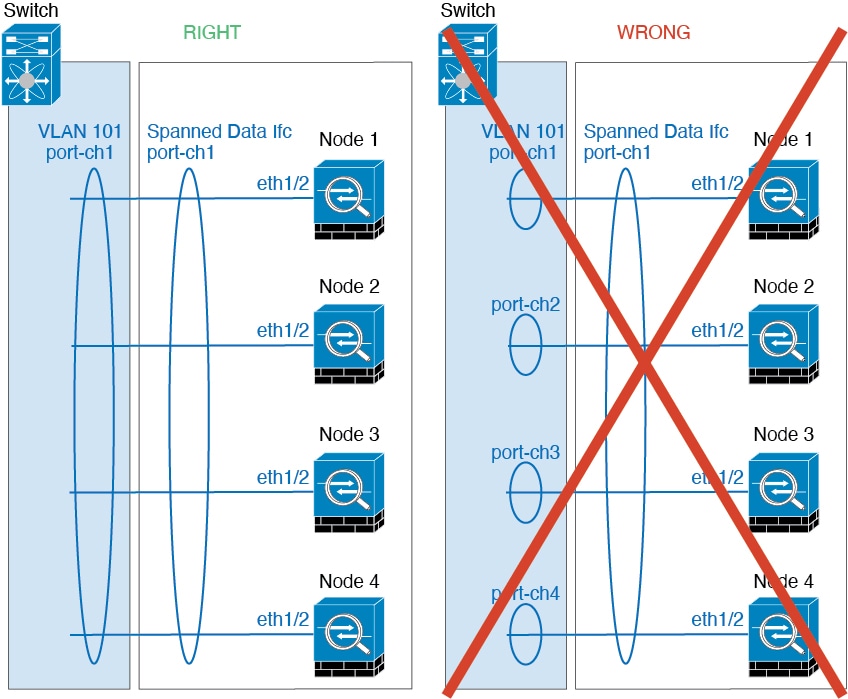
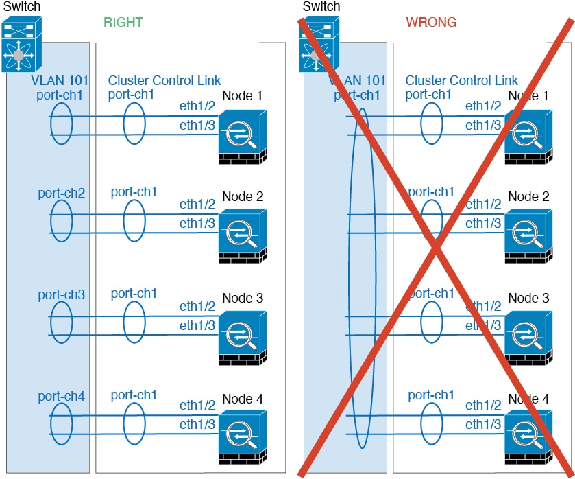
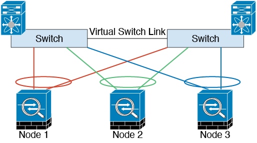
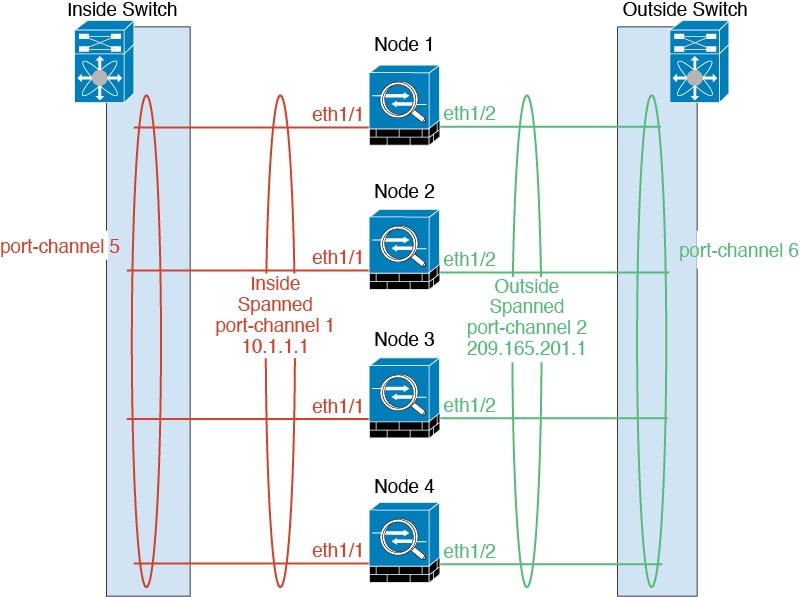
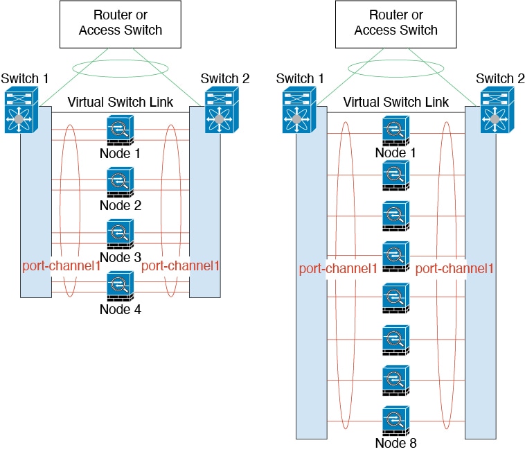
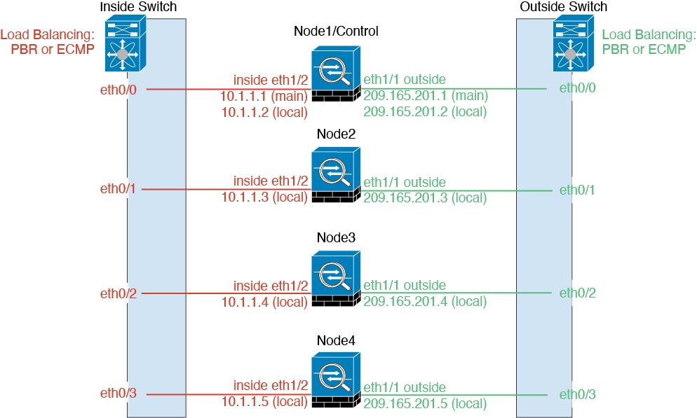

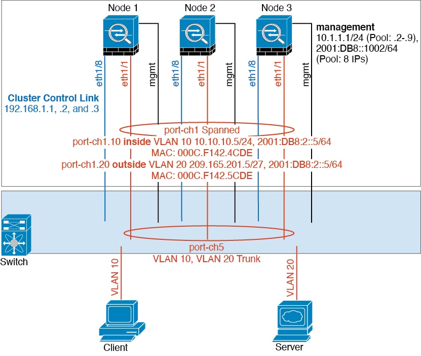
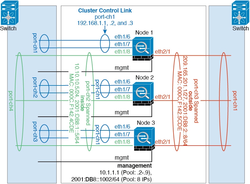
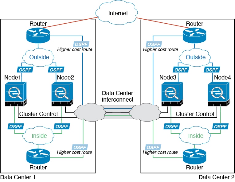
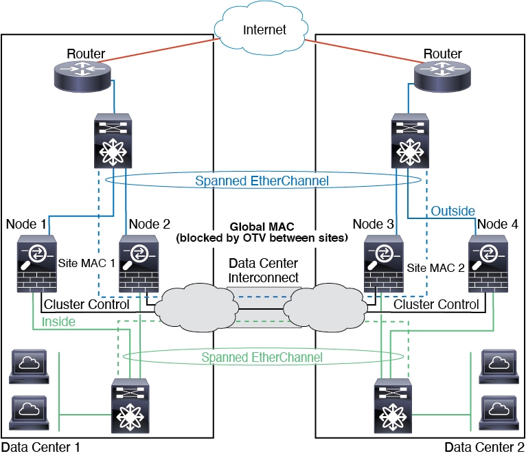
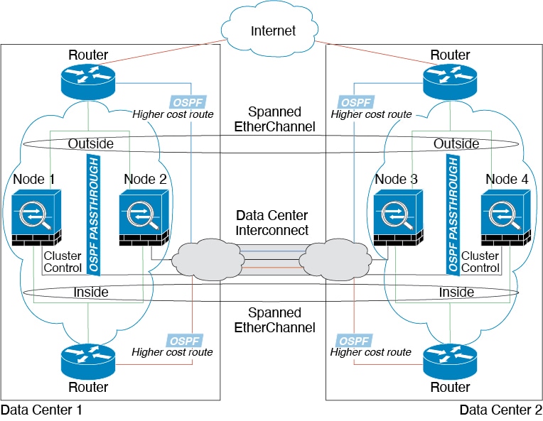
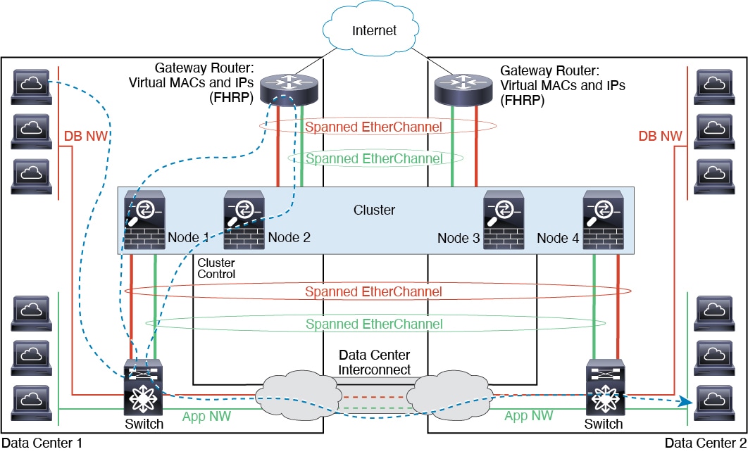
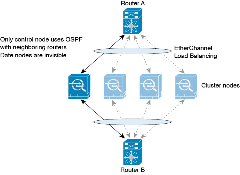
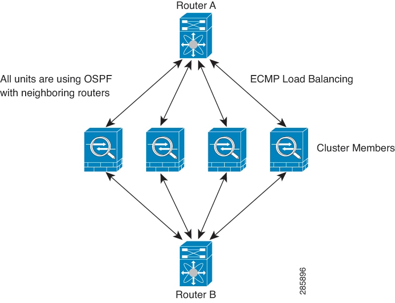
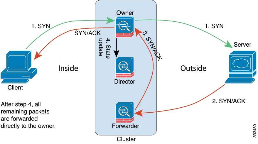
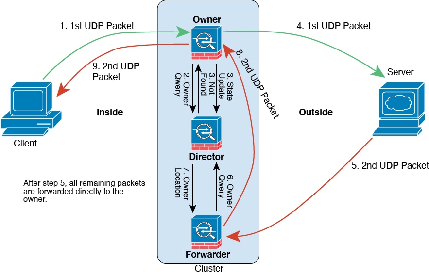
 Feedback