Classification TCAM with Cisco CloudScale ASICs for Nexus 9000 Series Switches White Paper
Available Languages
Bias-Free Language
The documentation set for this product strives to use bias-free language. For the purposes of this documentation set, bias-free is defined as language that does not imply discrimination based on age, disability, gender, racial identity, ethnic identity, sexual orientation, socioeconomic status, and intersectionality. Exceptions may be present in the documentation due to language that is hardcoded in the user interfaces of the product software, language used based on RFP documentation, or language that is used by a referenced third-party product. Learn more about how Cisco is using Inclusive Language.
- US/Canada 800-553-2447
- Worldwide Support Phone Numbers
- All Tools
 Feedback
 Feedback
CloudScale ASIC Classification TCAM Architecture
CloudScale ASIC Ingress Forwarding Controller
CloudScale ASIC Egress Forwarding Controller
CloudScale ASIC TCAM Scalability
CloudScale ASIC Default ACL TCAM Allocation
Nexus 9300-EX, Nexus 9364C, nexus 9332C (4K ingress, 2K Egress)
Nexus 9300-FX, Nexus 9300-FX2, Nexus 9300-FX3, Nexus 9300-GX (5K Ingress,2K Egress)
Nexus 9300-GX2A, 9300GX2B, 9408 (6K Ingress, 3K Egress)
Nexus 9300-H2R, 9300-H1 (14K Shared)
ACL TCAM Regions for QoS Policy
Ing-redirect, Ing-sup and Egr-sup TCAM Regions
Layer 2 and Layer 3 SPAN Filter TCAM Regions
NetFlow and Analytics TCAM Region
Non-Blocking Multicast (NBM) TCAM Region
Hardware Statistics "ing-cntacl" and "egr-cntacl" TCAM Regions
Front Panel to ASIC Slice Mapping
Maximum Label Sizes Supported for ACL Types
Classification ACL Design Considerations
Scaling TCAM Usage with Slices
Cisco Nexus Dashboard Data Broker
ACL TCAM Space Utilization with Object Groups
Logical Operators and Logical Operation Units (LOUs)
Introduction
In 2016, Cisco made its debut of the Cisco Nexus® 9000 Series Switch line with products built on the revolutionary Cisco® Cloud Scale intelligent Application-Specific Integrated Circuits (ASICs). These initial Cloud Scale platforms enabled customers to establish high-performance, cost-effective data center networks, offering a transition from 10G and 40G Ethernet to more robust 25G and 100G connectivity options. Over the following years, Cisco continued to expand and enhance the product family with additional platforms, introducing numerous innovations to address the evolving demands of Cloud Scale data centers, converged and hyperconverged infrastructure, and virtualized and containerized applications.
The inclusion of 400G Ethernet technology further enriches the Cloud Scale portfolio by providing platforms that deliver high-density, top-of-rack aggregation, spine aggregation, and backbone connectivity options. These platforms utilize the GX, GX2A, GX2B, and the latest additions, H2R and H1 Cloud Scale ASICs. With 400G options available for both top-of-rack and modular systems, the Nexus 9000 series chassis stand at the forefront of the industry, incorporating innovations such as 400G QSFP-DD (double density) transceivers that offer full backward compatibility with existing QSFP28 (100G) and QSFP+ (40G) transceivers.
Cisco Nexus 9000 switches equipped with Cloud Scale ASICs operate in either NX-OS mode, based on Cisco NX-OS Software, or ACI mode, based on Cisco Application Centric Infrastructure (Cisco ACI™). This remarkable flexibility allows customers to deploy Cisco Nexus 9000 platform switches in the mode that best aligns with their current operational model. Additionally, it leaves the option open to migrate smoothly to the other mode without requiring additional hardware investment or replacement.
This comprehensive document provides an in-depth explanation of Cisco Cloud Scale ASIC ternary content-addressable memory (TCAM) carving in conjunction with the Nexus 9000 switch. It encompasses essential concepts, configurations, and error messages commonly encountered in this context. The primary aim of this document is to enable users to grasp the workings of TCAM allocation, facilitating the creation of customized configurations that align precisely with their requirements.
In situations where you need non-default features for the Nexus 9000, you must manually carve out TCAM space to accommodate these features. By default, the entire TCAM space is allocated, and this document equips users with the knowledge to optimize and tailor their TCAM usage for enhanced performance and functionality.
This document is for planning, implementation, and maintenance in DevOps teams.
The Cisco Nexus 9000 platform switches are equipped with cutting-edge Cisco Custom CloudScale technology ASICs. This unique approach of designing and owning both the silicon, Software SDK, and operating system confers significant competitive advantages to the Nexus 9000 series. It serves as a powerful vehicle for delivering an array of advanced features and functions.
Leveraging the advantages of the latest semiconductor device fabrication, these ASICs boast higher transistor density and lower power consumption. These features are crucial in enabling the creation of ASICs with increased bandwidth, a higher number of ports, larger forwarding tables, generous buffers, and the opportunity to implement novel, advanced capabilities.
Cisco's cloud-scale ASICs introduce a wide range of Ethernet speeds, including 25, 50, 100, 200, and 400 Gigabit Ethernet (GE), to data center networks at a cost point optimized for optimal performance. See Table 1 for the specific Cloud Scale ASICs used in each Cisco Nexus 9000 Switch Family. Table 2 highlights the major feature sets associated with each Cloud Scale ASIC.
Table 1 Cisco Could Scale ASIC family with their corresponding Nexus 9000 switch
| CloudScale ASIC |
Nexus 9000 Family |
Platforms and Line Cards |
| LS 1800 EX |
9300-EX, X9700-EX (LCs) |
C93180YC-EX, C93108TC-EX, C93180LC-EX, X9732C-EX, X9736C-EX, X97160YC-EX |
| LS 1800 FX |
9300-FX, X9700-FX (LCs) |
C93180YC-FX, C93108TC-FX, C9348GC-FXP, X9732C-FX, X9736C-FX, X9788TC-FX |
| LS 3600 FX2 |
9300-FX2 |
C9336C-FX2, C9336C-FX2-E, C93240YC-FX2, C93360YC-FX2, C93216TC-FX2 |
| LS 1800 FX3 |
9300-FX3 |
C93180YC-FX3, 93180YC-FX3S, C93108TC-FX3P, C93108TC-FX3, C9348GC-FX3, C9348GC-FX3PH |
| S 6400 |
9300C, FM-E2 (FMs) |
9364C, 9332C,9508-FM-E2, 9516-FM-E2 |
| LS 6400 GX |
9300-GX, X9700-GX (LCs) |
C9316D-GX, C93600CD-GX, C9364C-GX, X9716D-GX, 9504-FM-G, 9508-FM-G |
| LS 25600 GX2A LS 12800 GX2B |
9300-GX2A, 9300-GX2B, 9408 |
9364D-GX2A, 9348D-GX2A, 9332D-GX2B, C9400-SW-GX2A |
| LS 12800 H2R LS 6400 H1 |
9300-H2R, 9300-H1 |
9332D-H2R, 9364C-H1, C93400LD-H1 |
Table 2 Cisco Could Scale ASIC family features
| ASIC Feature |
LS 1800 EX |
LS 1800 FX |
LS 3600 FX2 |
LS 1800 FX3 |
S 6400 |
LS 6400 GX |
LS25600 GX2A |
LS12800 GX2B |
LS12800 H2R |
LS6400 H1 |
| Bandwidth (Tbps) |
1.8T |
1.8T |
3.6T |
1.8T |
6.4T |
6.4T |
25.6T |
12.8T |
12.8T |
6.4T |
| No. of Die/Slices |
1 Die 2 Slices |
1 Die 1 Slices |
1 Die 2 Slices |
1 Die 1 Slices |
1 Dies 4 Slices |
2 Dies 4 Slices |
1 Die 8 Chiplets 8 Slices |
1 Die 4 Chiplets 4 Slices |
2 Dies 4 Slices |
1 Die 2 Slices |
| Fabrication node |
16nm |
16nm |
16nm |
14nm |
16nm |
14nm |
7nm |
7nm |
7nm |
7nm |
| Max Ports (400/200/ 100/50 GE) |
0/0/ 18/72 |
0/0/ 18/72 |
0/0/ 36/72 |
0/0/ 18/72 |
0/0/ 64/0 |
16/32/ 64/128 |
64/128/ 256/256 |
32/64/ 128/128 |
32/64/ 128/128 |
16/32/ 64/128 |
| Buffer/Max-per-port (MB) |
37.4/18.7 |
40/40 |
40/30 |
40/40 |
40/10 |
80/20 |
120/30 |
120/60 |
80/40 |
40/40 |
| External Deep Buffer |
N/A |
N/A |
N/A |
N/A |
N/A |
N/A |
N/A |
N/A |
8G HBM |
N/A |
| Telemetry |
FT
|
FT, FTE |
FT, FTE, SSX |
FT, FTE, SSX |
SSX |
FT, FTE, SSX, INT-XD, INT-Transparent |
FT, FTE, SSX, INT-XD |
FT, FTE, SSX, INT-XD |
FT, FTE, SSX, INT-MX, INT-MD, INT-XD |
FT, FTE, SSX, INT-MX, INT-MD, INT-XD |
| Hardware Entries/Tiles |
544K/17 |
1088K/34 |
544K/17 |
1088K/34 |
352K/11 |
1088K/34 |
640K/20 |
1280K/40 |
1280K/40 |
1280K/40 |
| Classification TCAM (Ingress/ |
4K/2K |
5K/2K |
5K/2K |
5K/2K |
4K/2K |
5K/2K |
6K/3K |
6K/3K |
14K Shared |
14K Shared |
CloudScale ASIC Classification TCAM Architecture
CloudScale ASIC Ingress Forwarding Controller
The ingress forwarding controller operates as follows: when a packet is received from the MAC layer, it parses the packet headers and conducts several lookups to determine whether the packet should be accepted and how it should be forwarded to its intended destination. Additionally, the controller generates instructions for the data path to handle the storage and queuing of the packet. For a visual representation of this process, see Figure 1, showcasing the CloudScale ASIC ingress forwarding controller.
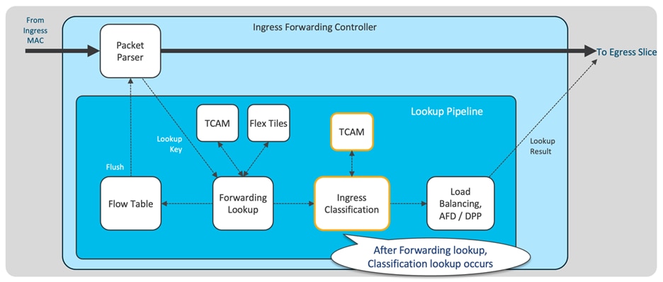
Figure 1 Cisco Could Scale ASIC ingress forwarding controller
After forwarding lookups, the packet undergoes ingress classification processing. The ingress matches are verified against the classification TCAM. These ACLs comprise various types, such as Routed ACLs (RACLs), VLAN ACLs (VACLs), Port ACLs (PACLs), Quality of Service (QoS), Network Address Translation (NAT) ACLs, and others.
CloudScale ASIC Egress Forwarding Controller
The egress forwarding controller is tasked with receiving packets from the buffer manager, along with their corresponding metadata, for transmission purposes. Its primary responsibilities include egress classification and managing all packet rewrites. You can observe the representation of the "Egress Forwarding Controller" in Figure 2, where the egress classification takes place. Egress RACLs and VACLs are the most commonly allocated TCAM resources for egress classification. Additionally, starting with LS25600 GX2A CloudScale ASICs, Egress PACLs are also supported.
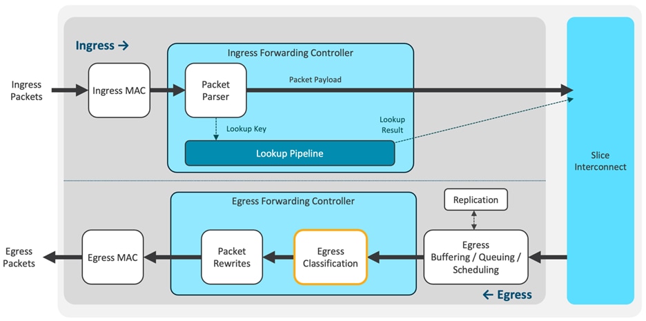
Figure 2 Cisco Could Scale ASIC egress forwarding controller
The classification entries are confined to individual ASIC slices and are programmed only where required. This approach optimizes the utilization of the classification TCAM in Cisco Nexus 9000 platform switches. In Figure 3, you can see that each ASIC is equipped with TCAM to support both system internal ACLs and user-defined ingress ACLs.
With the exception of LS12800 H2R and LS6400 H1, all Cloud Scale ASICs have dedicated ingress and egress TCAM space. On the other hand, LS12800 H2R and LS6400 H1 share a 14K TCAM space, which serves for both ingress and egress classifications.
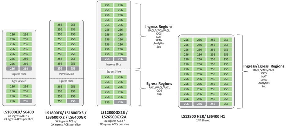
Figure 3 Cisco Could Scale ASIC ACL TCAM architecture
The carving of any region size is limited to values only in multiples of 256 entries, except for the SPAN region and NAT regions, which can only be carved in multiples of 512 entries. Notably, the "ing-sup" region requires a minimum size of 512 entries, while the "egr-sup" region necessitates a minimum size of 256 entries. You cannot configure these regions with lower values.
The Cisco CloudScale-based Nexus 9000 TCAM boasts a simplified design as compared to Merchant Silicon-based platforms. See Figure 4 for the ACL types supported by Cisco CloudScale ASICs.
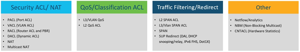
Figure 4 Cisco CloudScale ASIC supported ACL types
The TCAM regions can handle entries of IPv4, IPv6, or MAC types, without the need for single- or double-wide configurations. Additionally, there is no requirement for QoS-lite regions. This approach significantly simplifies the ACL TCAM configuration for users of Nexus 9000 switches. For a visual comparison of the classification TCAM regions between the merchant silicon-based Nexus 9000 and the CloudScale-based Nexus 9000, see Figure 5.
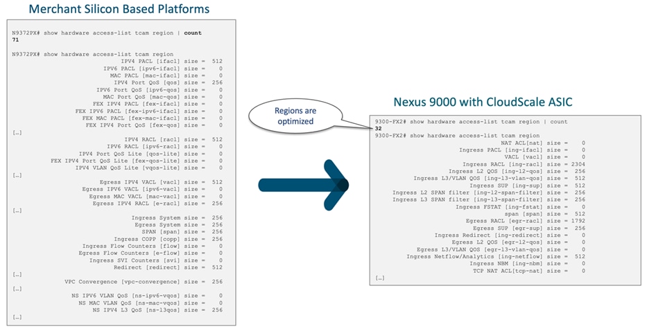
Figure 5 Classification TCAM regions between merchant silicon-based Nexus 9000 and the CloudScale based Nexus 9000
CloudScale ASIC TCAM Scalability
The Cloud Scale ASIC TCAM is optimized for scalability through slice-aware policy programming. PACL and RACLs are programmed only on slices where ports with these ACLs are present, and port channel ACLs are programmed solely on slices where the respective members exist. Similarly, VLAN ACLs are programmed exclusively on slices where the corresponding VLAN is present. To enable policy sharing, labels are used with label space localized to each slice. For specific Cisco CloudScale ASIC ACL TCAM scalability numbers, see Table 3. It's important to note that the TCAM scalability numbers were verified with all TCAM regions freed up except for the 'ing-sup' and 'egr-sup' regions.
Table 3 Cisco Cloud Scale ASIC ACL TCAM scalability numbers
| ASIC |
Ingress PACL |
Egress PACL |
Ingress RACL |
Egress RACL |
Ingress VACL |
Egress VACL |
||||||
| Name/Slices |
Per Slice |
Total |
Per Slice |
Total |
Per Slice |
Total |
Per Slice |
Total |
Per Slice |
Total |
Per Slice |
Total |
| LS1800 EX (2 slices) |
3584 |
7168 |
1792 |
3584 |
3584 |
7168 |
1792 |
3584 |
1792 |
3584 |
1792 |
3584 |
| LS1800 EX (1 slice) |
4608 |
4608 |
1792 |
1792 |
4608 |
4608 |
1792 |
1792 |
1792 |
1792 |
1792 |
1792 |
| LS3600 FX2 (2 slices) |
4608 |
9216 |
1792 |
3584 |
4608 |
9216 |
1792 |
3584 |
1792 |
3584 |
1792 |
3584 |
| LS1800 FX3 (1 slice) |
4608 |
4608 |
1792 |
1792 |
4608 |
4608 |
1792 |
1792 |
1792 |
1792 |
1792 |
1792 |
| S 6400 (4 slices) |
3584 |
14336 |
1792 |
7168 |
3584 |
14336 |
1792 |
7168 |
1792 |
7168 |
1792 |
7168 |
| LS 6400 (4 slices) |
4608 |
18432 |
1792 |
7168 |
18432 |
1792 |
1792 |
7168 |
1792 |
7168 |
1792 |
7168 |
| LS25600 GX2A (8 slices) |
5632 |
45056 |
2816 |
22528 |
5632 |
45056 |
2816 |
22528 |
2816 |
2258 |
2816 |
22528 |
| LS12800 GX2B (4 slices) |
5632 |
22528 |
2816 |
11264 |
5632 |
22528 |
2816 |
11264 |
2816 |
11264 |
2816 |
11264 |
| LS12800 H2R (4 slices) |
13568 |
54272 |
13568 |
54272 |
13568 |
54272 |
13568 |
54272 |
13568 |
54272 |
13568 |
54272 |
| LS6400 H1 (2 slices) |
13568 |
27136 |
13568 |
27136 |
13568 |
27136 |
13568 |
27136 |
13568 |
27136 |
13568 |
27136 |
CloudScale ASIC Default ACL TCAM Allocation
The allocation of both ingress and egress ACL TCAM to different ACL types is user configurable. Each ACL type requires its dedicated bank/banks, and ACL programming is localized on a per ASIC basis. ACL entries are programmed into the TCAM only where they are required. By default, all available TCAM regions are allocated, except for Nexus 9300-GX2 and Nexus 9408 chassis.
In the case of Cisco Nexus 9300-H2R and 9300-H1, they are the only Nexus platforms with shared TCAM space for both Ingress and Egress slices. The default assignment is 10K for ingress and 4K for egress, although any bank can be reconfigured to function as either ingress or egress.
To illustrate the default classification TCAM regions for the Nexus 9300 series switches, see Figure 6 for 9300-EX and 9300C, Figure 7 for 9300-FX/FX2/FX3/GX, Figure 8 for 9300-GX2A/GX2B and 9408, and finally, Figure 9 for 9300-H2R/H1.
Nexus 9300-EX, Nexus 9364C, nexus 9332C (4K ingress, 2K Egress)
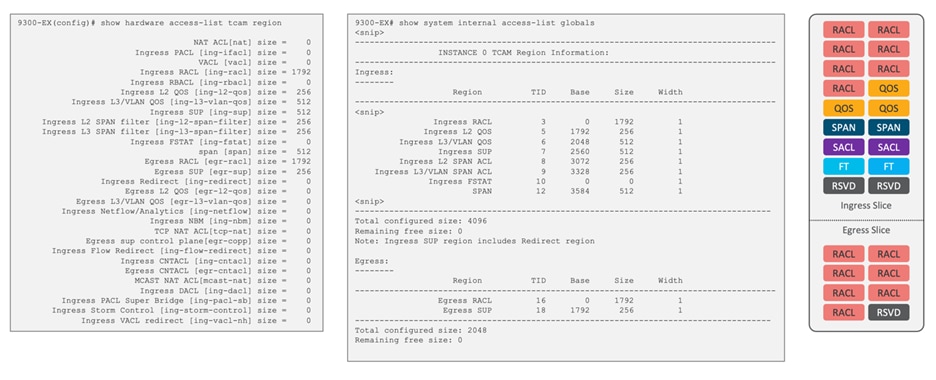
Figure 6 Default classification TCAM regions for Cisco Nexus 9300-EX and 9300C
Nexus 9300-FX, Nexus 9300-FX2, Nexus 9300-FX3, Nexus 9300-GX (5K Ingress,2K Egress)
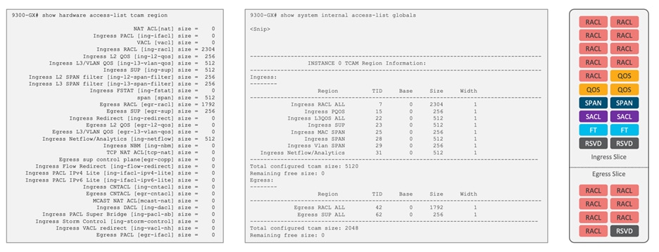
Figure 7 Default classification TCAM regions for Cisco Nexus 9300-FX/FX2/FX3/GX chassis
Nexus 9300-GX2A, 9300GX2B, 9408 (6K Ingress, 3K Egress)
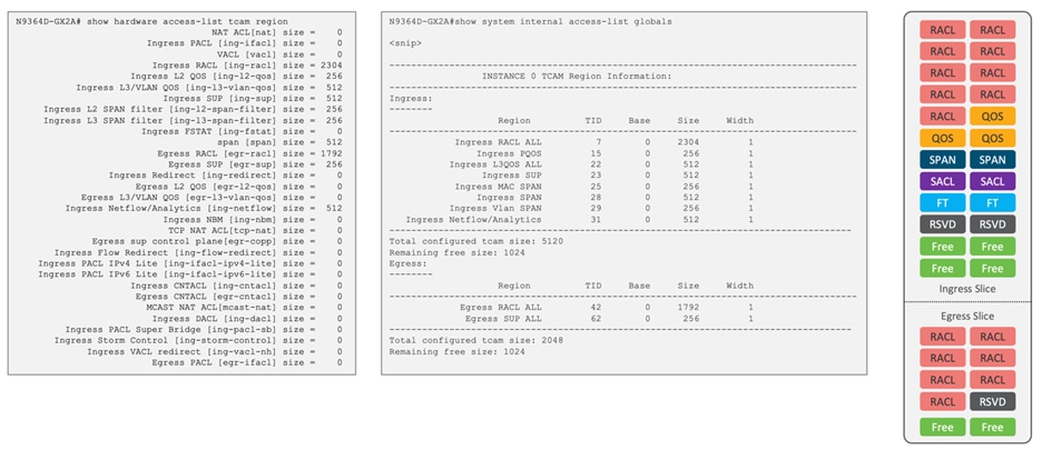
Figure 8 Default classification TCAM regions for Cisco Nexus 9300-GX2A/GX2B and Cisco Nexus 9408 chassis
Nexus 9300-H2R, 9300-H1 (14K Shared)
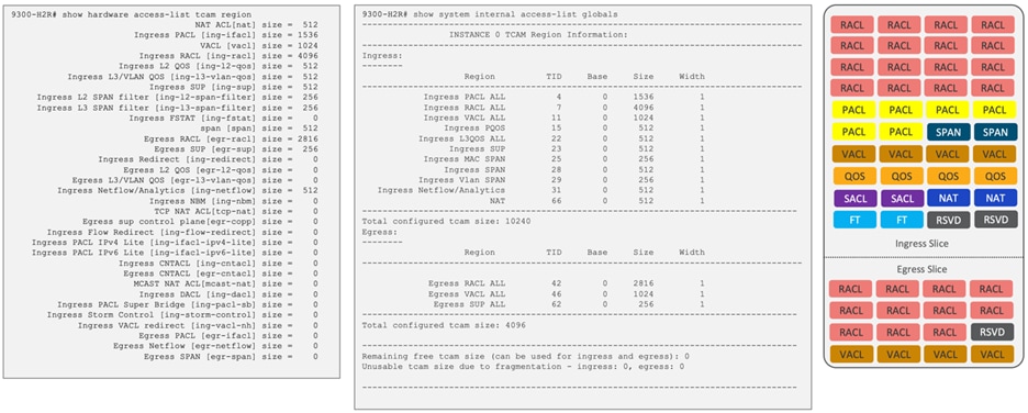
Figure 9 Default classification TCAM regions for Cisco Nexus 9300-H2R/H1 chassis
If a non-default feature is required for Nexus 9000, you must manually allocate TCAM space for those features. By default, all TCAM space is allocated, except for Nexus 9300-GX2 and Nexus 9408 chassis. If you wish to assign more banks to a specific region, you must first free up an equal number of banks from other regions before allocating them to the targeted region.
For example, in Figure 10, we can observe the TCAM carving for Cisco Nexus 9300-FX3, where no entries are initially allocated to NAT. However, for NAT, a minimum of 512 entries in TCAM will be needed to accommodate the required functionality.
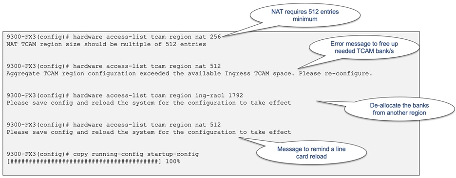
Figure 10 TCAM carving for NAT
Modifications to ACL TCAM region carving necessitate a switch/line card reload. When configuring the "hardware access-list tcam region" command, the changes only apply to the software allocation. To enforce the reallocation of regions in the hardware, you must reload the system, as depicted in Figure 11.
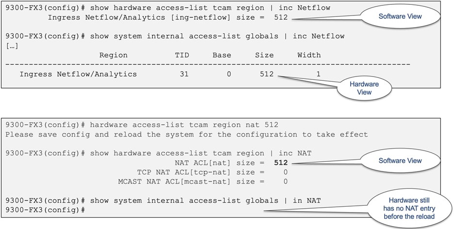
Figure 11 Software and hardware show commands for NAT TCAM allocation
The distinction between single- and double-wide regions does not apply to Cloud Scale ASICs. For examle, the ing-ifacl region is capable of accommodating IPv4, IPv6, or MAC type entries. IPv4 and MAC types occupy one TCAM entry, whereas IPv6 types occupy two TCAM entries. When using the "show system internal access-list globals" command, all allocated regions display a single width, as illustrated in Figure 12.
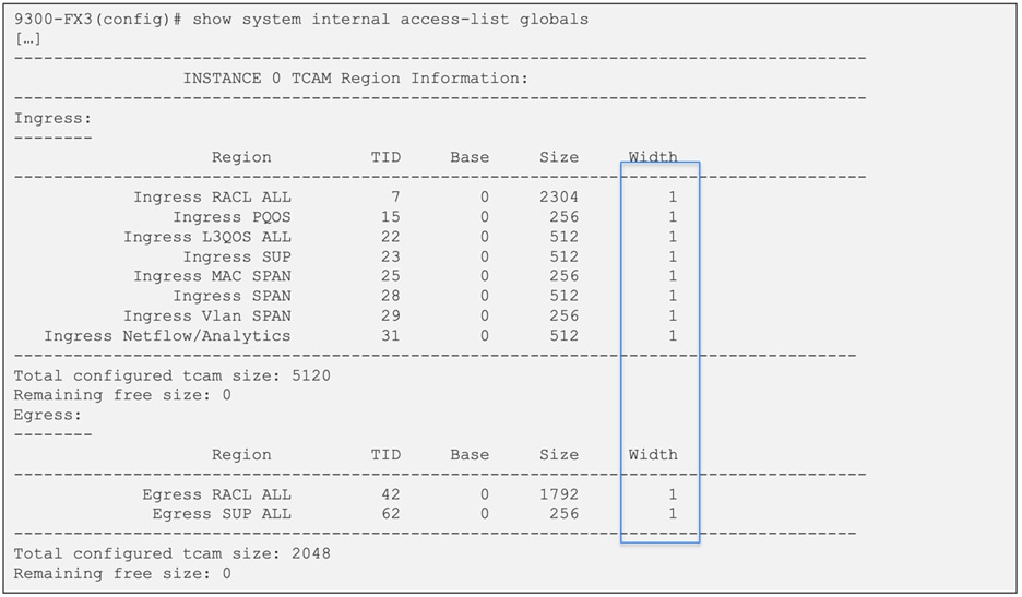
Figure 12 Simplified TCAM regions with Cisco CloudScale ASIC
The security Access Control Lists (ACLs) are divided into three distinct categories, namely PACL, VACL, and RACL. Table 4 clearly defines each category, along with providing a configuration example. Policy-based routing (PBR) also makes use of the ingress RACL region.
It is essential to emphasize that traditionally, PACL has been utilized in the ingress direction with Cisco Nexus 9000 switches, making the PACL TCAM region applicable solely for ingress operations. However, with the advent of Cisco NX-OS release 10.2(1)F, egress PACL is now supported on the Nexus 9364D-GX2A and 9332D-GX2B platform switches. Moreover, the support for egress PACL has been extended to the Nexus 9348D-GX2A with 10.2(3)F and Nexus 9408 running 10.3(2)F release.
Table 4 Cisco Cloud Scale ASIC security ACL TCAM regions
| Name |
Description |
CLI Configuration |
Region Name |
| PACL |
ACL applied to a Layer 2 switchport interface. It cannot be applied on any other type of interface, and it works only in the ingress direction with exception of 9300-GX2 where an egress PACL is also supported. The security boundary is to permit or deny traffic within a VLAN. PACL TCAM is automatically shared when the same PACL is applied to multiple ports on the same ASIC. Only supported in the ingress direction. |
ip access-list pacl permit tcp any any interface Ethernet 1/1 switchport ip port access-group pacl in |
●
ing-ifacl: For ingress IPv4, IPv6, and MAC port ACLs.
●
egr-ifacl: For ingress IPv4, IPv6, and MAC port ACLs. Only supported with 9300-GX2 and Nexus 9408 chassis.
|
| VACL |
ACL that is applied to a VLAN. It can be applied only to a VLAN, not any other type of interface. The security boundary is to permit or deny moving traffic between VLANs and permit or deny traffic within a VLAN. |
ip access-list vacl permit ip any 10.1.1.0 0.0.0.255 vlan access-map myvacl 10 match ip address vacl action forward vlan filter myvacl vlan-list 10-15 |
● vacl: The same TCAM size is allocated to both ingress and egress.
|
| RACL |
ACL that is applied to an interface that has a Layer 3 address assigned to it. It can be applied to any port that has an IP address, such as routed interfaces, loopback interfaces, and VLAN interfaces. The security boundary is to permit or deny traffic moving between subnets or networks. |
ip access-list racl permit ip host 1.1.1.1 host 2.2.2.20 interface e1/1 no switchport ip address 2.2.2.1 255.255.255.0 ip access-group racl in |
● ing-racl: For ingress IPv4 and IPv6 RACLs and PBR.
● egr-racl: For egress IPv4 and IPv6 RACLs.
|
When configuring the VACL region, the same value is allocated for both ingress and egress. As a result, you must ensure that both the ingress and egress TCAM regions have sufficient space. If the specified region size cannot fit in either direction, the configuration is rejected, as shown in Figure 13.
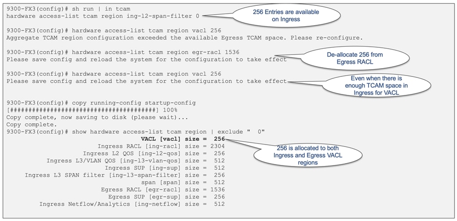
Figure 13 VACL region need to match for both ingress and egress
After reloading the chassis, both ingress and egress VACL regions undergo modifications, as illustrated in Figure 14.
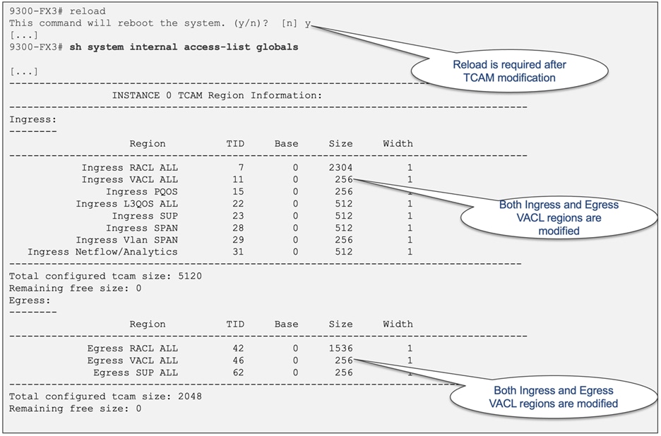
Figure 14 Hardware entries for both ingress and egress VACL after system reboot
For IPv4 RACLs, each Access Control Entry (ACE) occupies one entry in TCAM. Additionally, a single entry is utilized for the implicit deny all clause based on the ACL logic. Figure 15 illustrates this utilization for both a single line and a two-line ACL.
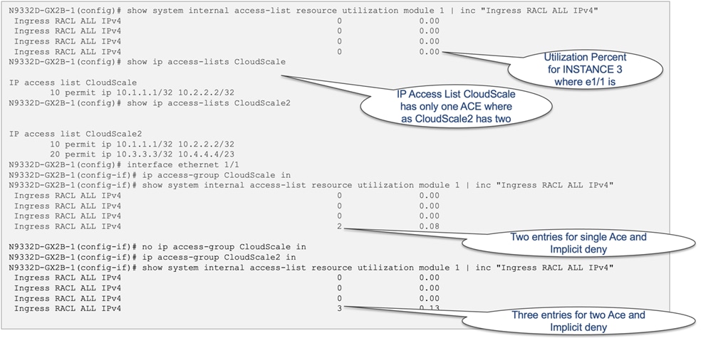
Figure 15 RACL utilization for one and two ACE entry RACLs
In cases where you configured a Layer 4 match within the ACL, an additional fragment ACE per Layer 4 match is introduced. Figure 16 illustrates this utilization for a single-line ACL with a Layer 4 range.
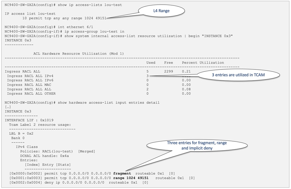
Figure 16 RACL utilization for L4 port range
For IPv6 RACLs, each Access Control Entry (ACE) line occupies two entries in the TCAM. For example, as shown in Figure 17, if the IPv6 RACL has only one ACE line, it utilizes (1+1 implicit deny) x 2 entries in the TCAM.
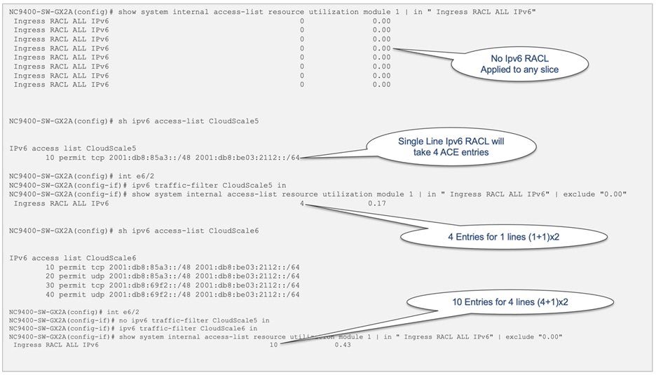
Figure 17 TCAM utilization for IPv6 RACLs
By default, no TCAM entries are allocated for the NAT feature, except for Nexus 9300-H2R and Nexus 9300-H1. To enable the NAT feature, you must allocate TCAM space by adjusting the TCAM size of other features. You can achieve this using the "hardware access-list tcam region nat tcam-size" command. In Cisco Nexus 9000 family switches, NAT utilizes the TCAM table for packet matching based on IP address or port. If you attempt to configure a TCAM-required feature before allocating sufficient TCAM space, the configuration is rejected when it is applied to the interface. For the specific configuration of NAT TCAM on Cisco Nexus 9300-GX, see Figure 18. As always, you must reload the system for the TCAM configuration to take effect. In the event that a required TCAM region for a particular feature is removed while the feature is in use, after the switch is reloaded, the interface-level configuration of that specific feature is also removed. Figure 19 illustrates an example of NAT configuration removal after the NAT TCAM region has been taken out.
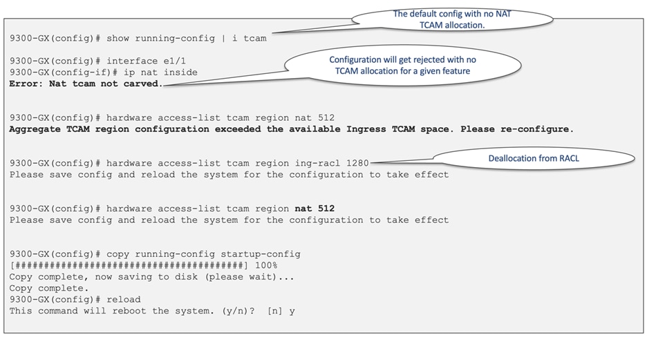
Figure 18 TCAM allocation for NAT with Nexus 9300-GX
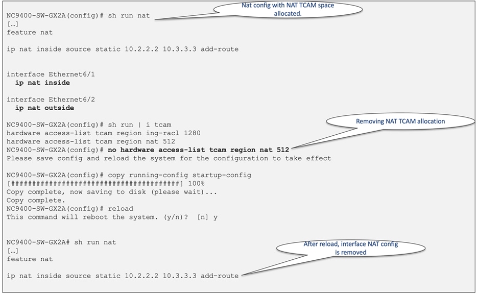
Figure 19 Interface configuration removal after TCAM space deallocation
In addition to the TCAM table, NAT rewrites and translations are stored in the "NAT Rewrite Table," which exists outside of the NAT TCAM region. The 'NAT Rewrite Table' has a fixed size of 2048 entries for Nexus 9300-EX/FX/FX2/9300C and 4096 entries for Nexus 9300-FX3/GX/GX2A/GX2B/H2R/H1. This table is exclusively used for NAT translations.
Each Static NAT/PAT entry for inside or outside source addresses requires two NAT TCAM entries and one "NAT Rewrite Table" entry, as shown in Figure 20. Additionally, Figure 21 illustrates the NAT translation architecture with Cisco Nexus 9000.
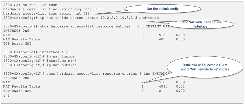
Figure 20 Static NAT/PAT TACM utilization
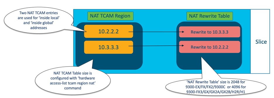
Figure 21 NAT TCAM region and the "NAT Rewrite" table
The utilization of NAT TCAM and the "NAT Rewrite Table" depends on the specific NAT configuration. For example, a static twice NAT configuration will allocate 6 TCAM entries and 5 "NAT Rewrite Table" entries, as depicted in Figure 22. It is important to note that all ASIC slices will have identical allocation for NAT resources.
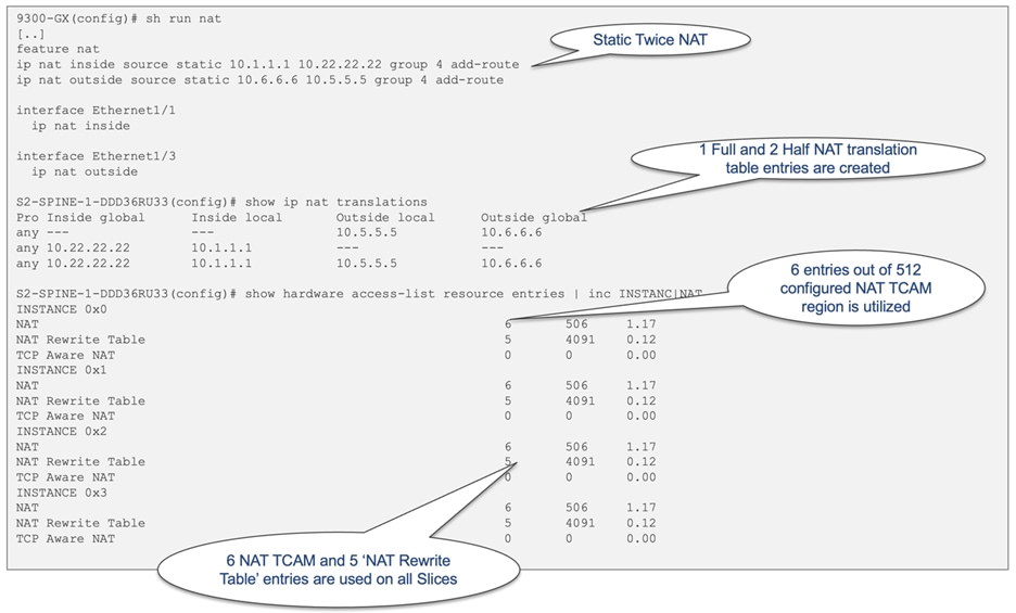
Figure 22 Static twice NAT TCAM allocation
The Multicast Service Reflection feature enables you to translate externally received multicast destination addresses to addresses that conform to your organization's internal addressing policy. It is the multicast Network Address Translation (NAT) of an externally received multicast stream (S1,G1) to (S2,G2) into the internal domain. Unlike IP NAT, which only translates the source IP address, Multicast Service Reflection translates both the source and destination addresses. For Nexus 9000 to support the Multicast Service Reflection feature, you must carve the "mcast-nat" TCAM region before configuring multicast NAT. Figure 23 illustrates a sample configuration for Multicast Service Reflection.
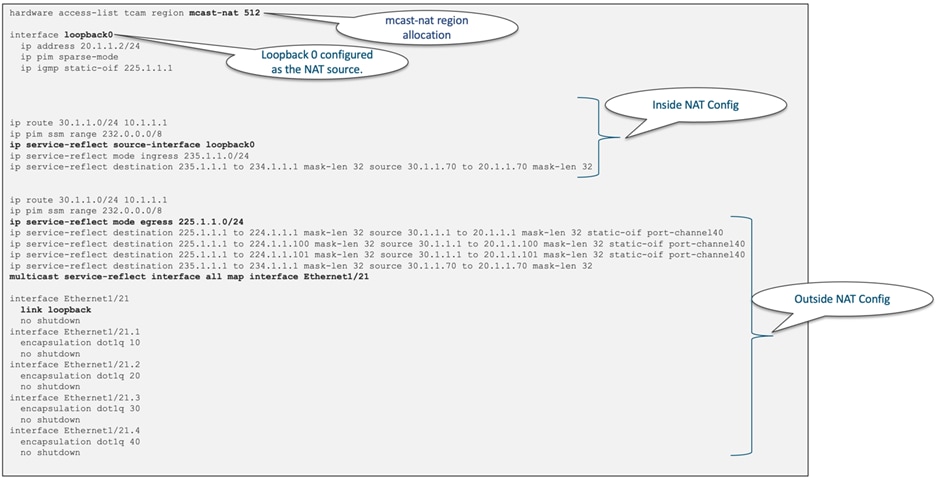
Figure 23 Multicast service reflection configuration
Dynamic ACL (DACL) is a single ACL that contains permissions of what users and groups can access. It restricts access to the dot1q MAB client. The DACL policy is pushed from the Cisco ISE server to block list a MAC address. It applies ACLs on the block listed MAC, enabling limited access to the MAB. A single DACL supports all block listed MAB clients. For all block listed clients, DACLs support a single global ACL on the switch. The ACL name received from the centralized ISE server should match the preconfigured ACL name on the switch. Block listed client traffic is filtered based on the fixed ACL rules applied for DNS, DHCP, and BOOTPC protocols. For the specifics of the DACL TCAM regions, see Table 5.
Table 5 Cisco Cloud Scale DACL TCAM region
| Name |
Description |
CLI Configuration |
Region Name |
| DACL |
Dynamic ACL (DACL) is a single ACL that contains permissions of what users and groups can access. It restricts access to the dot1q MAB client. DACLs support authentication only by MAC Authentication Bypass. In Cisco NX-OS release 9.3(5), the DACL is preconfigured on the Cisco Nexus switches. Beginning with Cisco NX-OS release 9.3(5), DACLs are supported on Cisco Nexus 9336-FX2, Nexus 9236C, Nexus 93108TC-EX, and Nexus 93180YC-EX switches. Beginning with Cisco NX-OS release 10.1(2), DACLs are supported on the N9K-C9364D-GX2A and N9K-C9332D-GX2B platform switches. |
hardware access-list tcam region ing-dacl 256 ip access-list creative_blocklist |
ing-dacl: For ingress only. The configured ACL name on the device must match the acl-name received from the ISE server. The ACL policy is pushed from the ISE server. "show ip access-lists dynamic" displays the details. |
ACL TCAM Regions for QoS Policy
Cisco Nexus 9000 supports three types of policy maps: network-qos, QoS, and queueing. The QoS policy map is primarily used for classification, marking, and policing, mostly on ingress, except for egress policing. The queueing policy map, on the other hand, is utilized for egress queueing and scheduling. Among these three types, only the QoS policy requires TCAM resources.
QoS policies can be applied to Layer 3 interfaces, switch ports, port channels, VLANs, and logical interfaces such as Network Virtual Interface (NVE). The specific QoS TCAM region to be carved depends on where the policy is applied and which classifier is used. There are two QoS regions in the Cisco Cloud Scale ASIC:
1. The ingress Layer 2 QoS or "ing-l2-qos" region is used when classification is on a Layer 2 interface. The same TCAM bank is shared for MAC, IPv4, and IPv6 entries. IPv4 and MAC types occupy one TCAM entry, whereas IPv6 types occupy two TCAM entries.
2. The ingress Layer 3/VLAN QoS or "ing-l3-vlan-qos" is used when classification is on a Layer 3 or SVI interface. Similar to "ing-l2-qos," the TCAM bank is shared for MAC, IPv4, and IPv6 entries.
For the specifics of the two QoS ACL TCAM regions, see Table 6.
Table 6 Cisco Cloud Scale ACL TCAM regions for QoS policy
| Name |
Description |
CLI Configuration |
Region Name |
| Ingress Layer 2 QOS |
When classification is on a Layer 2 interface. The same TCAM bank is shared for MAC, IPv4, and IPv6 entries. IPv4 and MAC types occupy one TCAM entry whereas IPv6 types occupy two TCAM entries. |
class-map type qos match-any class_dscp match dscp 18 policy-map type qos CS_policy class class_dscp set qos-group 2 interface Ethernet 6/3 switchport switchport mode trunk service-policy type qos input CS_policy |
ing-l2-qos: For ingress IPv4, IPv6, and MAC port ACLs. |
| Ingress Layer 3/VLAN QOS |
When classification is on a Layer 3 or SVI interface. The same TCAM bank is shared for MAC, IPv4, and IPv6 entries. IPv4 and MAC types occupy one TCAM entry whereas IPv6 types occupy two TCAM entries. |
class-map type qos match-any class_dscp match dscp 18 policy-map type qos CS_policy class class_dscp set qos-group 2 interface Ethernet 6/2 service-policy type qos input CS_policy ip address 172.16.33.1/24 |
ing-l3-vlan-qos: For ingress IPv4, IPv6, and MAC port ACLs. |
Ing-redirect, Ing-sup and Egr-sup TCAM Regions
With the Cisco Nexus 9000 switch family, the "ing-redirect" TCAM region is considered as additional entries to the "ing-sup" region. Control plane traffic, such as BFD and CoPP, exclusively utilizes the "ing-sup" region. For DHCPv4/v6, the default configuration utilizes the "ing-sup" region, and no additional TCAM carving is required. However, when you enable the "ip dhcp relay subnet-broadcast" command, more TCAM entries per subnet/per interface become necessary. As a result, with the use of the "ip dhcp relay subnet-broadcast" command, DHCP also requires the "ing-redirect" TCAM region.
On the other hand, the "egr-sup" region is reserved for system messages. The default TCAM entry for the "ing-sup" region is 512 for Nexus 9300 and 768 for Nexus 9500 with CloudScale ASIC LCs. For the "ing-redirect" region, the default TCAM entry is 0 for Nexus 9300 and 256 for Nexus 9500 with CloudScale ASIC line cards. You must increase the default "ing-sup" and "egr-sup" regions with large custom Control Plane Policing (CoPP) policies.
It is important to note that the "ing-sup" region cannot be set lower than 512 entries, while the minimum size for the "egr-sup" region is 256 entries. For a visual representation of the required minimum entries for these regions, see Figure 24.
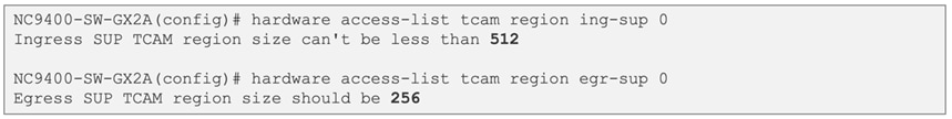
Figure 24 Minimum required space for "ing-sup" and "egr-sup"
SPAN TCAM entries are essential when enabling SPAN on Cisco Nexus 9000 switches for any port and any port type. However, a VLAN filter used in SPAN also utilizes the SPAN region, and no additional region is required for it. Additionally, sFlow also utilizes the TCAM SPAN region.
Starting with the Cisco Nexus 9300-FX2 model, simultaneous utilization of sFlow and SPAN features becomes viable. However, for earlier Nexus 9300-EX and Nexus 9300-FX models, activating both SPAN and sFlow features concurrently is not achievable. The default allocation for the SPAN TCAM region is 512 entries, and it can only be carved in multiples of 512 entries. For a visual representation of the default SPAN region allocation, see Figure 25.
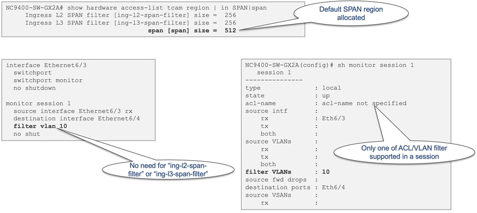
Figure 25 Default SPAN region allocation for Cisco Nexus 9408 chassis
Layer 2 and Layer 3 SPAN Filter TCAM Regions
The Layer 2 and Layer 3 SPAN filter TCAM regions come into play when configuring access group filtering in a SPAN session. This ensures that only the traffic aligning with the ACL on the source interfaces will be subjected to SPAN. The "ing-l2-span-filter" region is necessary when SPAN filtering is applied to a Layer 2 port, while the "ing-l3-span-filter" region is used when SPAN filtering is applied to a Layer 3 interface. Both Layer 2 and Layer 3 SPAN filter regions are initially allocated with 256 entries in the default configuration.
When setting up an access-group filter in a SPAN session, it must be configured as a vlan-accessmap. However, the VACL region is not required for SPAN ACL filter support. To better understand the use case for these two regions, see Figure 26.
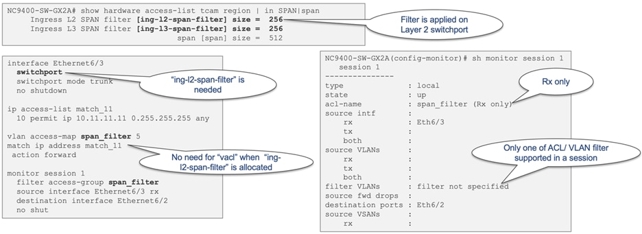
Figure 26 Ingress Layer 2 and Layer 3 SPAN filter use case
NetFlow and Analytics TCAM Region
Cisco NX-OS supports the flexible NetFlow feature that enables enhanced network anomalies and security detection by identification of packet flows for ingress IP packets and provides statistics based on these packet flows. Flexible NetFlow allows customers to define an optimal flow record for a particular application by selecting the keys from a large collection of predefined fields.
By default, all Cisco Nexus 9300 switches have 512 TCAM entries allocated to the "ing-netflow" TCAM region and no additional carving is needed for NetFlow to work. This region is also used for flow table hardware telemetry that is exported to Cisco Nexus Dashboard Insights (NDI).
Non-Blocking Multicast (NBM) TCAM Region
In IT data centers, Equal-Cost Multipath (ECMP) is highly efficient due to the predominance of Transmission Control Protocol (TCP)-based traffic, which generates numerous flows and results in a more uniform distribution of the load across all paths. However, in media data centers that handle uncompressed video, audio, and ancillary flows, ECMP routing may not always be efficient. In such scenarios, there's a risk that all video flows will be hashed along the same path, causing oversubscription of that particular path.
To address the limitations, Cisco developed the Non-Blocking Multicast (NBM) process on NX-OS, which enhances the intelligence of PIM. NBM introduces bandwidth awareness to PIM, allowing it to consider bandwidth availability when setting up flow paths. By combining NBM and PIM, a network can achieve intelligent and efficient multicast delivery, preventing oversubscription and ensuring sufficient bandwidth for the multicast traffic.
By default, the "ing-nbm" region is not allocated any TCAM space. Figure 27 illustrates the TCAM allocation for the "ing-nbm" region.
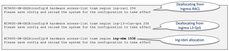
Figure 27 Ingress NBM TCAM allocation
Hardware Statistics "ing-cntacl" and "egr-cntacl" TCAM Regions
Starting from Cisco NX-OS release 10.1(1), the "hardware forwarding ip statistics" command allows customers to enable the Nexus 9000 Switch to export hardware forwarded IPv4/IPv6 interface statistics. These statistics include interface IPv4 and IPv6 Rx and Tx packets, as well as byte counters, which can be polled through SNMP using the ipIfStatsTable.
By default, Cisco NX-OS exports only IPv4/IPv6 interface counters for the packets forwarded by the IPv4/IPv6 Netstack software running on the SUP CPU. With the introduction of the "hardware forwarding ip statistics" command, you can now retrieve additional hardware forwarded interface statistics through SNMP. To configure "hardware forwarding ip statistics" on a device, you must carve the required CNTACL TCAM region. To better understand the use case for these two regions, see Figure 28.
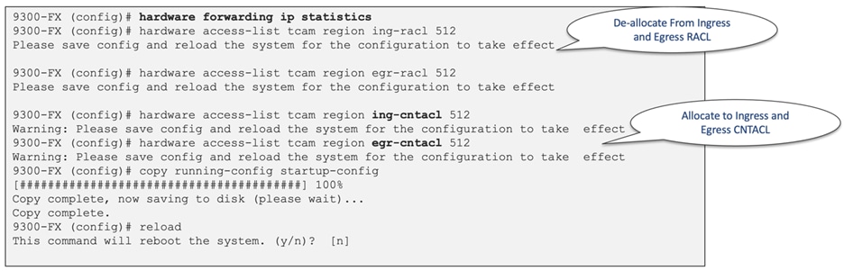
Figure 28 Hardware statistics configuration example
A CloudScale ASIC slice refers to a self-contained forwarding complex responsible for handling both ingress and egress functions for a specific subset of ports. Each slice is further divided into separate sections for ingress and egress functions. The ingress portion of each slice is interconnected to all egress portions of other slices via a slice interconnect, which enables non-blocking any-to-any interconnection between slices. For a visual representation of the Cisco CloudScale ASIC slice architecture, see Figure 29.
When it comes to ACLs, PACL and RACLs are exclusively programmed on slices that have ports associated with these ACLs. Similarly, VLAN ACLs are programmed on slices that have the respective VLAN present. Likewise, port channel ACLs are programmed only on slices where the members of the port channel are present.
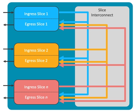
Figure 29 CloudScale ASIC slice architecture
The Cisco LS1800FX ASIC, utilized in Nexus 9300-FX, and the LS1800FX3 ASIC, used in Nexus 9300-FX3, both come with a single slice. However, the Nexus X9700-FX line cards are equipped with multiple ASICs, resulting in each line card having multiple slices. For example, the X9788TC-FX line card has two ASICs, thus having a total of two slices. Similarly, the X9732C-FX and X9736-FX line cards have four slices each. For a visual representation of the single slice ASIC architecture, see Figure 30. Each slice is represented by a unique instance number, which can be obtained from the "show system internal access-list globals" command.
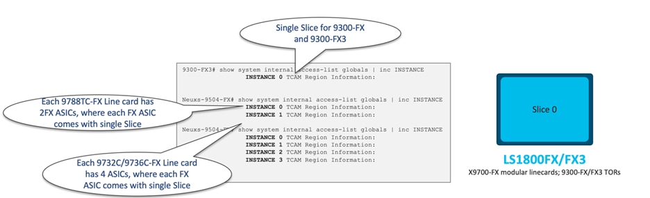
Figure 30 CloudScale ASICs with single slice
The Cisco LS1800EX ASIC, employed in Nexus 9300-EX, and the LS3600FX2 ASIC, used in Nexus 9300-FX2, along with the LS6400H1 ASIC utilized in Nexus 9300-H1, all come with two slices. For a visual representation of the two-slice ASIC architecture, see Figure 31.
Furthermore, the X97160YC-EX line card is equipped with two ASICs, resulting in a total of four slices. Similarly, the X9732C-EX and X9736-EX line cards will have a total of 8 slices.
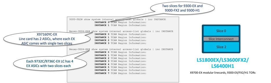
Figure 31 CloudScale ASICs with two slices
The Cisco S6400 ASIC, utilized in Nexus 9300C, and the LS6400GX ASIC, used in Nexus 9300-GX, X9716D-GX line card, LS12800GX2B used in 9300-GX2B, and LS12800H2R used in 9300-H2R, all consist of 4 slices. However, the X9716D-GX Line card has only two LS6400GX ASICs, resulting in a total of 8 slices for that line card. For a visual representation of the 4 slice ASIC architecture, see Figure 32.
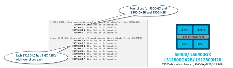
Figure 32 CloudScale ASICs with four slices
Lastly, the Cisco LS25600GX2A, utilized in Nexus 9300-GX2A, and the Nexus 9408 both have 8 slices. For a visual representation of the 8 slice ASIC architecture, see Figure 33.
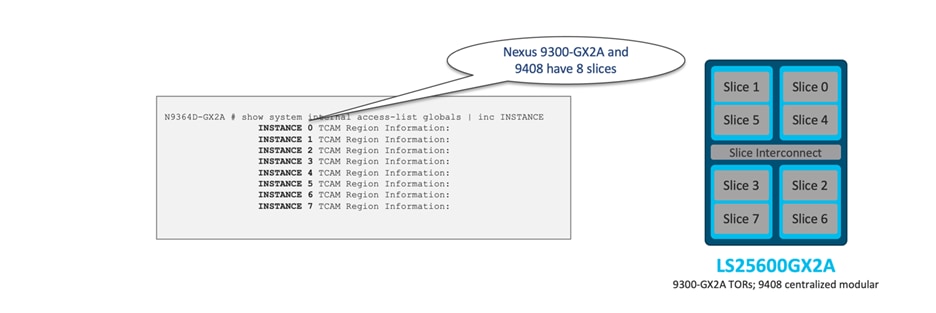
Figure 33 CloudScale ASICs with eight slices
Front Panel to ASIC Slice Mapping
When designing the network, understanding the linkage between front panel ports and each ASIC slice is crucial to maximize scalability, as each slice has its dedicated TCAM space. You can use the "show interface hardware-mappings" command to view the interface ASIC port mapping and its associated slice. For example, Figure 34 illustrates the port mapping for Nexus 9336-FX with a single LS3600FX2 ASIC, while Figure 35 shows the port mapping for Cisco Nexus X9732-EX with four LS1800EX ASICs.
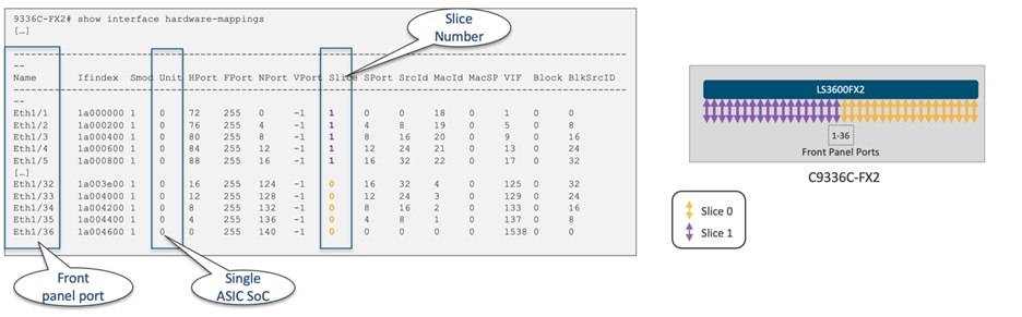
Figure 34 Cisco Nexus 9336-FX2 with single LS3600FX2 ASIC port mapping
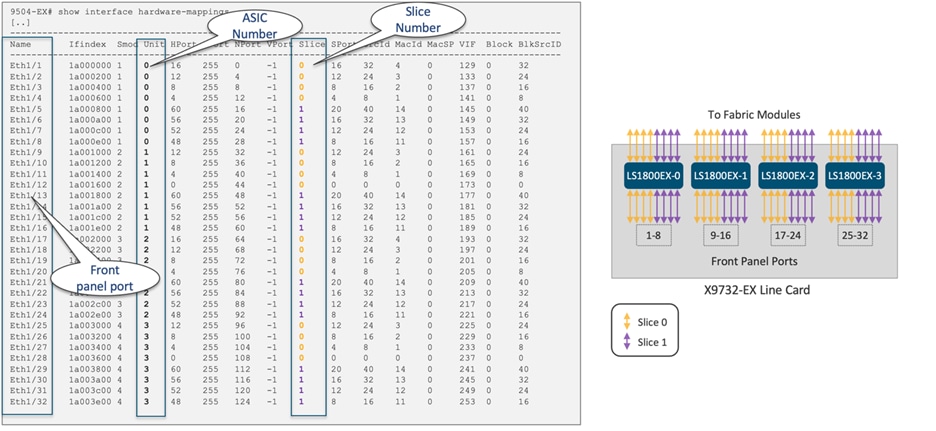
Figure 35 Cisco Nexus X9732-EX with four LS1800EX ASICs port mapping
When applying the same "set" of policies such as security ACLs (PACL, VACL, RACL), QoS or NAT to multiple interfaces or VLANs in a given direction (ingress or egress), only one copy is programmed in the TCAM, which is then shared among those interfaces and VLANs. To achieve this, each ACL policy is associated with a label. By assigning the same label to multiple interfaces and VLANs, the same TCAM rule can be applied to them all. However, only 62 unique ACLs can be configured per slice.
If the same ACL is configured on multiple interfaces, the same label is shared among them. Conversely, if each ACL has unique entries, the ACL labels are not shared. By default, ACL statistics are disabled, but they are enabled by default for QoS policies. Under ACL configuration, individuals have the option to activate ACL statistics using the "statistics per-entry" command through the CLI.
For label sharing to occur, the ACL target interfaces (such as port, VLAN, SVI) must be situated on the same slice, aside from sharing identical policies. Here's an example to illustrate this feature: Trunk ports E6/1 and E6/2 are part of Slice 3 of the LS25600GX2A ASIC. Before configuring any PACLs to these interfaces, the PACL TCAM utilization for Slice 3 is zero, as displayed in Figure 36.
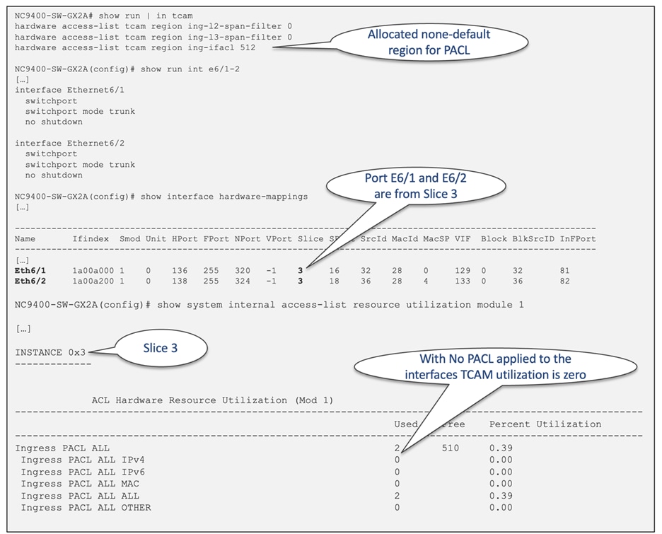
Figure 36 TCAM utilization before PACLs configured under E6/1 and E6/2
Once IPv4/IPv6/MAC PACLs are configured for interfaces E6/1, the PACL TCAM utilization for Slice 3 increases accordingly. To view the label allocated to interface E6/1, you can use the "show system internal access-list" command, which will display the information, as shown in Figure 37.
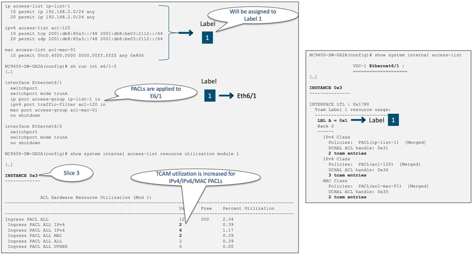
Figure 37 TCAM utilization after PACLs configured under E6/1
When the same PACL configuration is applied to interfaces E6/2, the PACL TCAM utilization for Slice 3 will not increase. This is because the same label (Label 1) is assigned to both E6/1 and E6/2. To view the labels allocated to interfaces E6/1 and E6/2, you can use the "show system internal access-list" command, which will display the information, as shown in Figure 38.
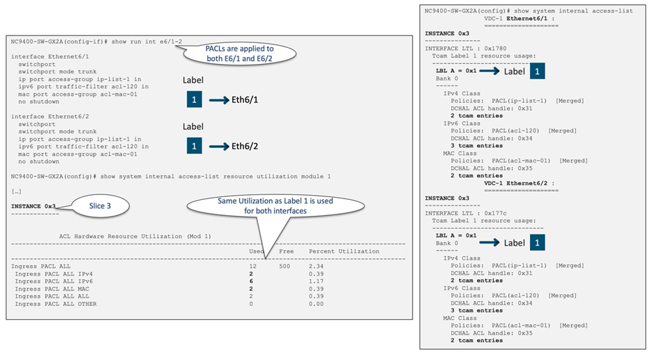
Figure 38 TCAM utilization after same PACLs configured under E6/1 and E6/2
To enable label sharing between interfaces, the ACL target (such as port, VLAN, and SVI) must belong to the same slice (in this example, Slice 3). Additionally, the same set of features and ACLs need to be configured under each interface. For example, if you remove the "mac port access-group" configuration from E6/2, the same label cannot be used for both E6/1 and E6/2, resulting in increased label/TCAM utilization, as depicted in Figure 39.
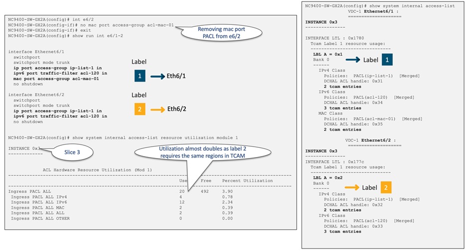
Figure 39 TCAM utilization after configuring different PACLs under E6/1 and E6/2
In this example, Label 1 currently utilizes 10 entries, and Label 2 utilizes 8 entries. When the MAC PACL was removed from E6/2, the TCAM utilization increased from 10 entries to 18 entries. Figure 40 provides a summary of this behavior.
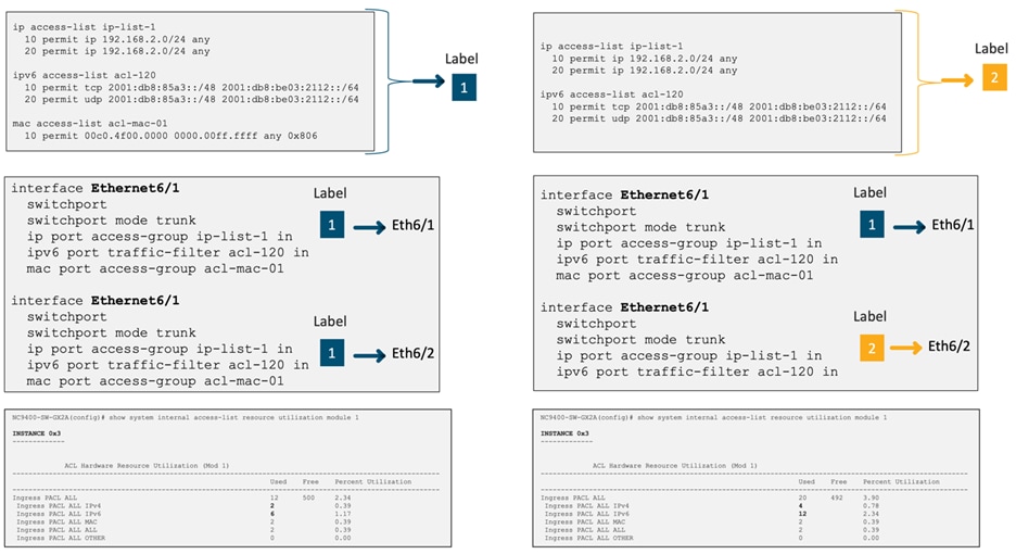
Figure 40 TCAM utilization with single label vs two labels
Table 7 illustrates the Nexus 9000 feature sets that will share the same label when applied to interfaces on the same slice.
Table 7 Cisco Nexus 9000 TCAM label sharing features
| Ingress Layer 3 |
Ingress Layer 2 |
Engress Layer 3 |
|
● Ingress RACL, VACL
● PBR
● Ingress Layer 3 QoS
● Layer 3/VLAN SPAN ACL
|
● Ingress PACL
● Ingress Layer 2 QoS
● Layer 2 SPAN ACL
|
● Egress RACL
● Egress QoS
|
As an example, if you configure the same ingress RACL and Ingress Layer 3 QoS policy on multiple interfaces allocated to the same slice, they all share the same label. However, if you remove QoS from one of the interfaces, it requires a new label, and this change might result in potentially utilizing more TCAM space. Figure 41 illustrates this scenario.
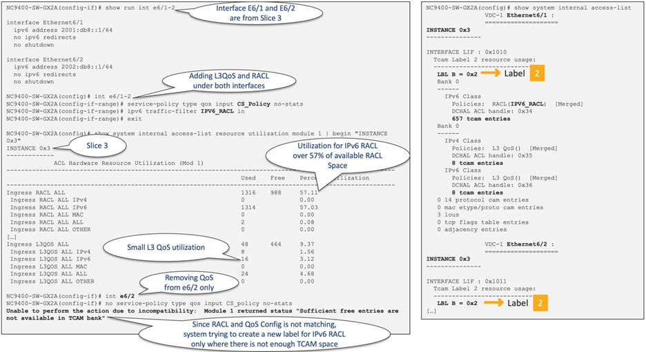
Figure 41 Ingress RACL and Ingress L3 QoS are sharing the same label
Maximum Label Sizes Supported for ACL Types
Table 8 presents the supported label sizes for various ACL types in Cisco NX-OS switches.
Table 8 Maximum label sizes supported for each ACL type
| ACL Types |
Platform |
Direction |
Max Label |
Reserved Label |
Size in Bits |
Label Type |
| RACL/PBR/VACL/L3-VLAN QoS/L3-VLAN SPAN ACL |
9300/9400 |
Ingress |
510 |
2 |
9 |
BD |
| RACL/PBR/VACL/L3-VLAN QoS/L3-VLAN SPAN ACL |
9500 |
Ingress |
62 |
2 |
6 |
BD |
| PACL/L2 QoS/L2 SPAN ACL |
9300/9400/9500 |
Ingress |
62 |
2 |
6 |
IF |
| RACL/VACL/L3-VLAN QoS |
9300/9400/9500 |
Egress |
254 |
2 |
8 |
BD |
| L2 QoS |
9300/9400/9500 |
Egress |
62 |
2 |
6 |
IF |
To enhance the default label size, users can utilize the "hardware access-list tcam label" command and subsequently reboot the switch. In Figure 42, there is a depiction of the process of augmenting the allocated ingress RACL region count to 512. This is achieved by adjusting the bit size from its initial value of 6 to 9. The default setting for the Ingress BD-Label size on Cisco Nexus 9300-GX, 9300-FX3, 9300-GX2A, 9408 and 9300-H2R/H1 is 512, requiring no further adjustments.
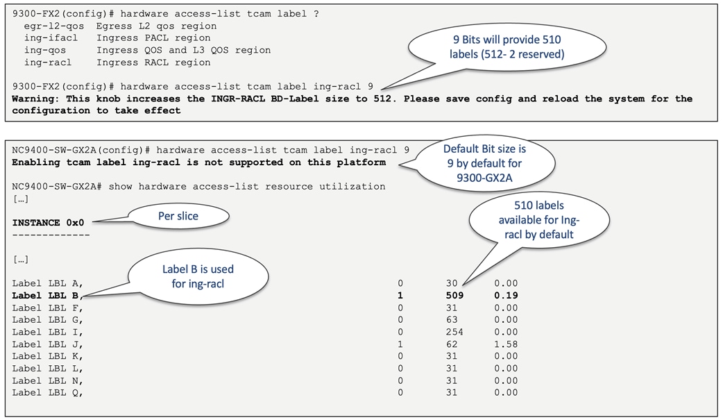
Figure 42 The allocated label size for 9300-FX2 and 9300-GX2A
Classification ACL Design Considerations
Scaling TCAM Usage with Slices
The CloudScale ASIC Slice mapping section notes that users have the ability to enhance the overall TCAM scale by strategically distributing the ACL policies across various front panel ports. In Figure 43, you can observe the LS25600 GX2A ASIC slices of the Cisco Nexus 9364D-GX2A, each of which is equipped with 6K ingress and 3K egress TCAM, along with 62/254/510 labels.
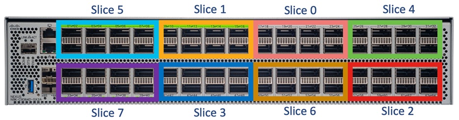
Figure 43 Nexus 9364D-GX2A front panel port and LS25600 GX2A ASIC slice allocations
By default, QoS TCAM sharing among interfaces or VLANs is not enabled to preserve per-policy stats. When multiple interfaces or VLANs have the same QoS policy, individual copies of the QoS policy are programmed for each interface or VLAN. However, TCAM sharing can be enabled by applying the QoS policy under interfaces or VLANs with the "no-stats" option using the configuration command "service-policy type qos input policy-name no-stats". After you enable TCAM sharing, the per-interface or per-VLAN statistics is no longer available. Figure 44 illustrates how label sharing is enabled for VLAN QoS.

Figure 44 How to enable label sharing for VLAN QoS
By default, when a Nexus 9000 switch equipped with the CloudScale ASIC updates an ACL, it performs an atomic ACL update. This type of update ensures that traffic traversing the interface where the change is being made is unaffected. However, an atomic update necessitates having enough available resources to store each updated ACL entry alongside all existing entries within the affected ACL. After the update completes, the additional resources utilized during the process are freed up.
In case there are insufficient free resources, an error is generated and no changes are applied to the hardware tables. You also have the option to disable atomic programming and perform the update non-atomically. You can do this by using the command "no hardware access-list update atomic", as shown in Figure 45.
When performing non-atomic programming, there will be a brief impact on the traffic, and by default, the affected traffic is dropped. However, this behavior can be changed by issuing the command "hardware access-list update default-result permit".
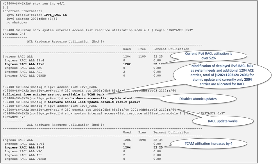
Figure 45 How to disable atomic update with Cisco Nexus 9000
Cisco Nexus Dashboard Data Broker
Cisco Nexus Dashboard Data Broker (NDDB) offers a straightforward, flexible, and cost-efficient solution for monitoring high-volume and mission-critical traffic. It replaces conventional, purpose-specific matrix switches by utilizing one or multiple Cisco Nexus 9000 series switches that can be interconnected to form a scalable network Test Access Port (TAP) and Cisco Switched Port Analyzer (SPAN) aggregation infrastructure, supporting data rates of 1, 10, 25/40, 100, and 400 Gbps.
When deploying a Cisco Nexus 9000 as a NDDB switch, you must allocate the PACL TCAM region, which is not preallocated by default. To achieve this, you can deallocate resources from the ingress and egress RACL as well as Layer 3 QoS (Quality of Service). For a better understanding, see Figure 46, which illustrates an example of the ACL TCAM configuration for the NDDB switch.
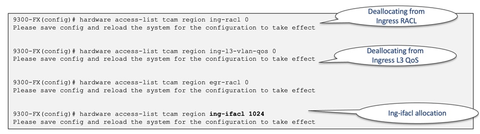
Figure 46 Cisco Nexus Data Broker ACL TCAM configuration
In scenarios where additional ACL filtering is expected with the NDDB switch, you can assign even greater TCAM entries to the 'ing-ifacl' region. Figure 47 demonstrates a 3K allocation to the 'ing-ifacl' region.
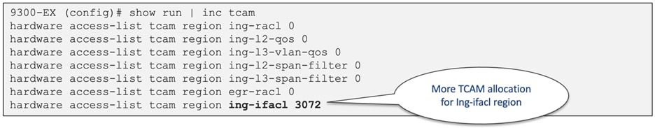
Figure 47 Cisco Nexus Data Broker ACL TCAM config for additional filtering
A label cannot be shared between a Layer 3 interface and an NVE interface even if the same policies are configured on them. Figure 48 illustrates the distinct label allocations for NVE and Layer 3 interfaces from the same slice.
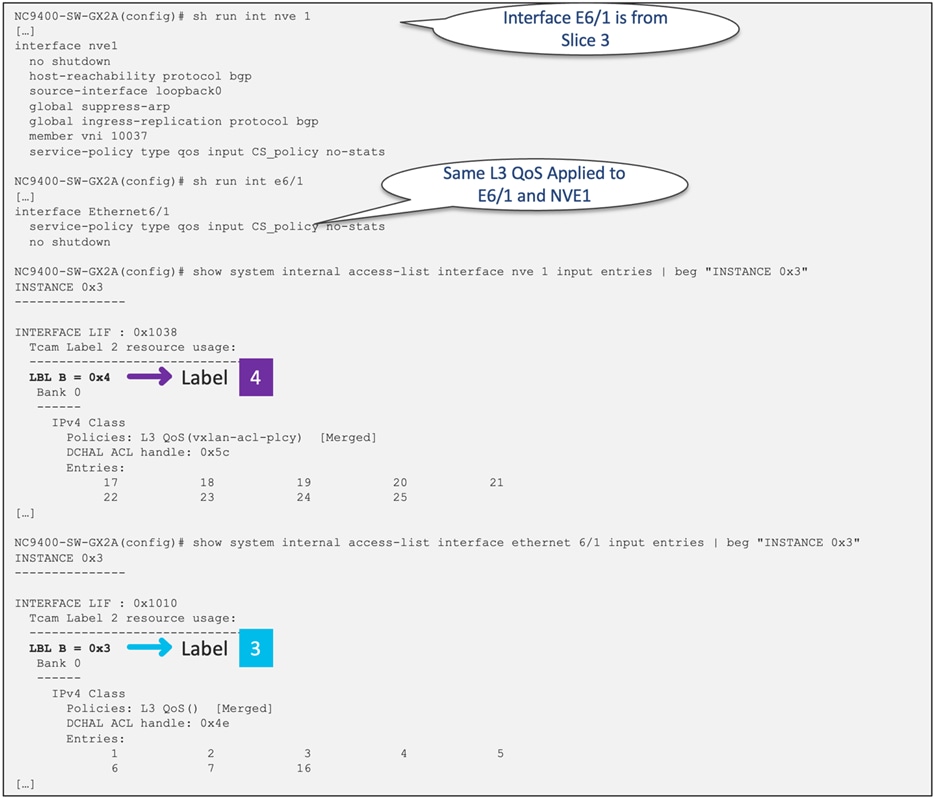
Figure 48 Different label allocation for interface e6/1 and Nve1
ACL TCAM Space Utilization with Object Groups
Utilizing object groups does not result in a reduced TCAM space utilization. The extension of TCAM when using Object Groups in conjunction with ACLs depends on the number of lines present in each Object group. For a visual representation of this concept, see Figure 49, which illustrates the IPv4 RACL utilization with various object groups.
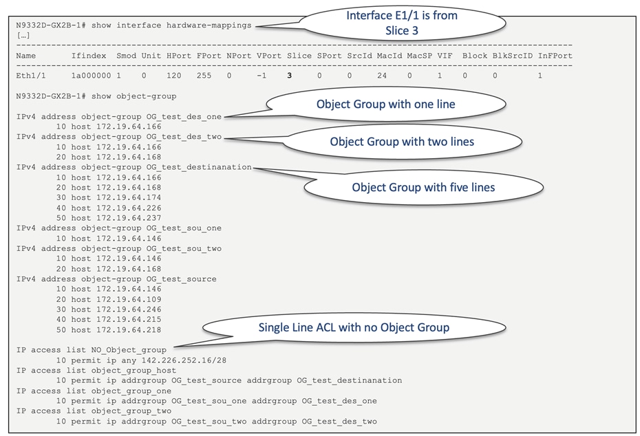
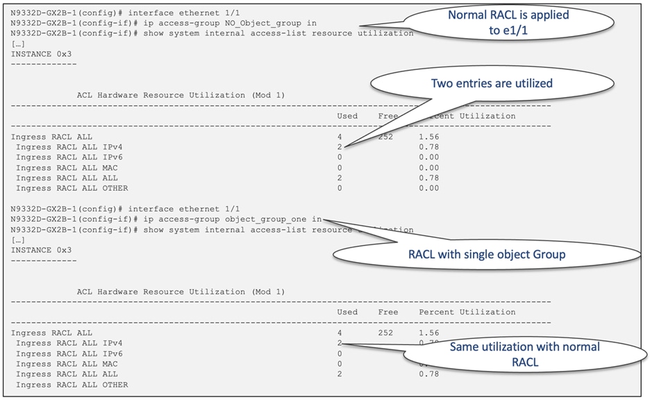
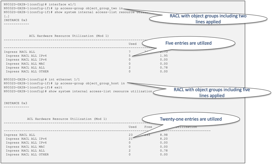
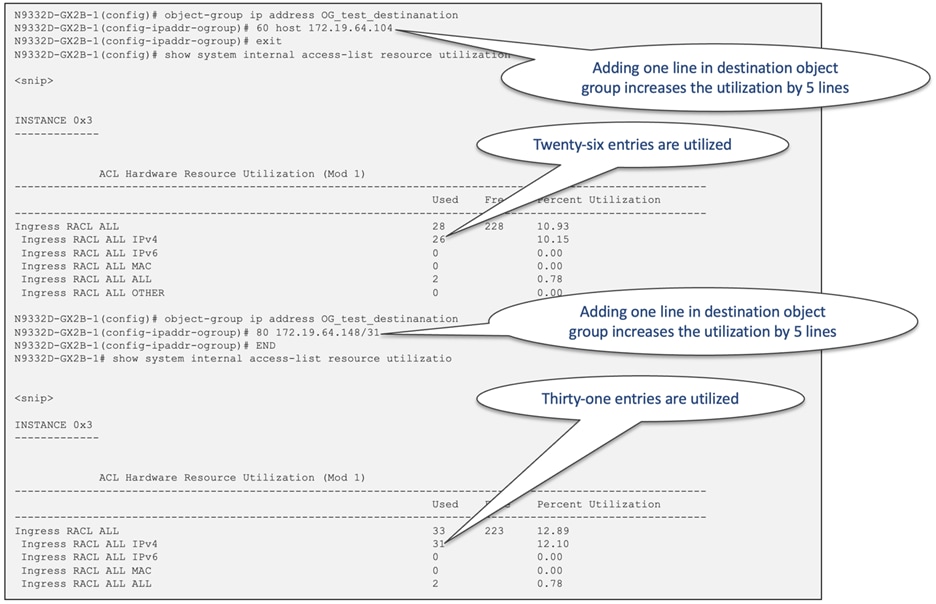
Figure 49 Object group impact on RACL TCAM utilization
Logical Operators and Logical Operation Units (LOUs)
IP ACL rules for TCP and UDP traffic can use logical operators to filter traffic based on port numbers in the ingress direction. Cisco Nexus 9000 stores operator-operand couples in registers called logical operator units (LOUs). Table 9 displays the LOU usage for each type of operator.
Table 9 LOU usage for each type of operator
| LOU Operator |
Direction |
| EQ (equal to) |
Is never stored in an LOU |
| GT (greater than) |
Uses 1 LOU |
| LT (less than) |
Uses 1 LOU |
| NEG (not equal to) |
Uses 1 LOU |
| Range |
Uses 1 LOU |
Within each CloudScale ASIC slice, there are a total of 15 LOU labels available, with 4 of them allocated for the default CoPP policy. Figure 50 exhibits the default LOU allocation for the NC9400-SW-GX2A model featuring the LS25600 GX2A ASIC.

Figure 50 The default LOU allocation for the NC9400-SW-GX2A
The "ACE Expansion Threshold" plays a pivotal role in determining how ACEs utilizing Layer 4 operators such as "range", "gt", "lt", and "neq" are managed. There are two distinct methods by which software handles these Layer 4 operators. The first approach involves the allocation of L4op, a hardware resource, alongside programming the LOU register, which is another hardware resource. Alternatively, ACEs can be expanded into multiple "eq" entries, effectively utilizing multiple ACL TCAM entries. The command "global hardware access-list lou resource threshold" governs the decision between these two options for each ACE. The expansion threshold, a key factor in this decision-making process, governs when ACE expansion occurs. By default, the threshold is set at 5. When an ACE can be expanded into 5 or fewer ACL TCAM entries, no L4op is allocated. You must weigh the pros and cons of these approaches. While expansion conserves L4op resources, it does consume more TCAM entries. Additionally, the utilization of L4op and LOU is constrained by their respective limits which is 15 labels per slice. Figure 51 and Figure 52 provide an illustrative example of a straightforward ACE extension, showcasing the impact of modifying the default threshold.
Starting from NX-OS 10.4(1)F, Layer 3 ePBR solutions will also support Layer 4 port operators such as port-range, "gt", "lt", and "neq". You can use these operators for selective redirection, load balancing, and service chaining based on the your specifications, aligning with the intended traffic filtering. Additionally, if you use ePBR you can modify the platform behavior for Layer 4 port operations by utilizing the "global hardware access-list lou resource threshold" command.
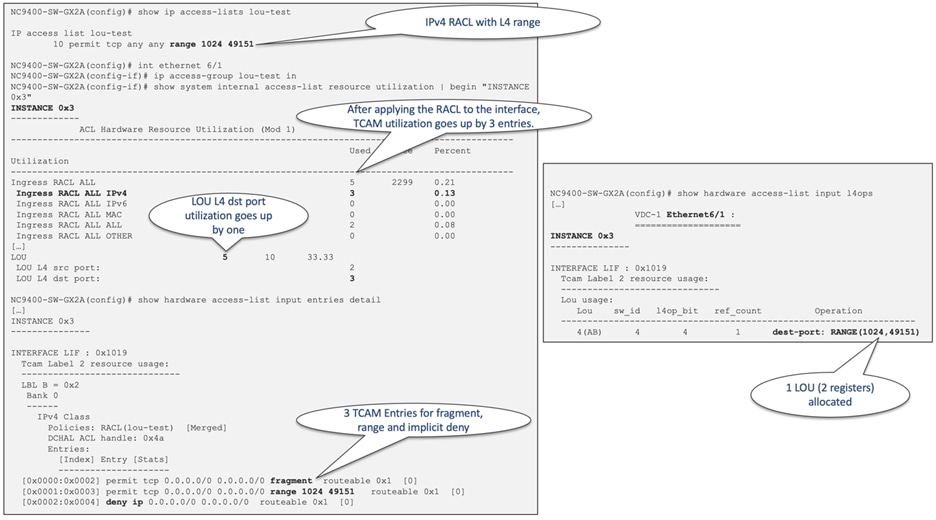
Figure 51 ACE extension example with default threshold of 5
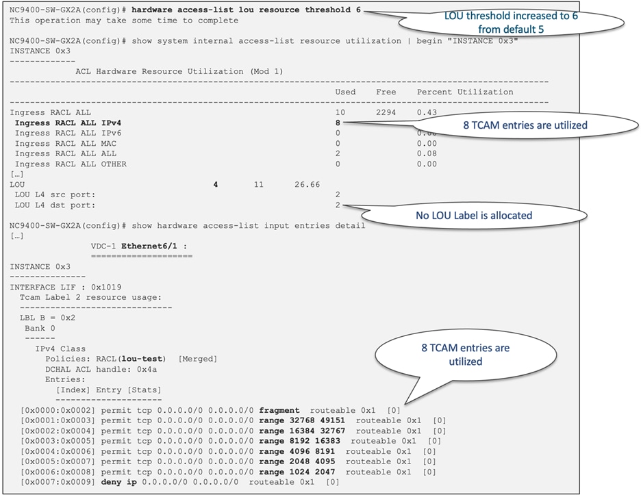
Figure 52 ACE extension example with modified threshold of 6
To ascertain the sufficiency of hardware resources (TCAM entries) prior to implementing an ACL or a QoS policy, employing a "Configuration Session" proves effective. During this process, users can set up ACLs and assign them to a designated interface. In instances where TCAM space is inadequate, the verification process will yield a failure. Referencing Figure 53 illustrates both a successful configuration session and an unsuccessful verification due to insufficient resources.
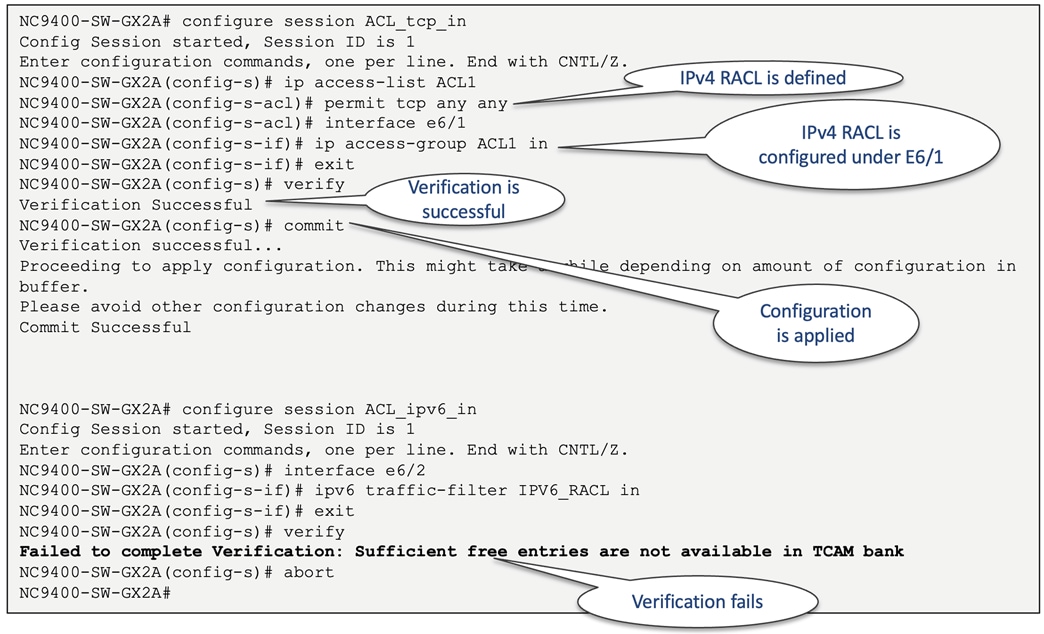
Figure 53 Configuration session examples
The Cisco Nexus 9000 platform switches incorporate Cisco's cutting edge CloudScale ASICs, which establish the benchmark for contemporary data center switching solutions. With simplified ACL TCAM regions and a versatile TCAM carving approach using multi-slice architecture, you can harness the full potential of classification table regions. This optimization strategy allows Nexus 9000 to leverage its TCAM space capabilities to the fullest, enabling you to achieve exceptional performance and efficiency in your data center operations.
● Cisco Nexus 9500 Cloud Scale Line Cards and Fabric Modules White Paper
● Cisco IP Fabric for Media White Paper
● Flexible Forwarding Table on Nexus 9000
● Layer 4 to Layer 7 Service Redirection with Enhanced Policy-Based Redirect White Paper