Configuring IP Tunnels

Information About IP Tunnels

IP tunnels can encapsulate a same-layer or higher layer protocol and transport the result over IP through a tunnel created between two devices.

IP Tunnel Overview

IP tunnels consists of the following three main components:

  • Passenger protocol—The protocol that needs to be encapsulated. IPv4 is an example of a passenger protocol.

  • Carrier protocol—The protocol that is used to encapsulate the passenger protocol. Cisco NX-OS supports GRE as a carrier protocol.

  • Transport protocol—The protocol that is used to carry the encapsulated protocol. IPv4 is an example of a transport protocol. An IP tunnel takes a passenger protocol, such as IPv4, and encapsulates that protocol within a carrier protocol, such as GRE. The device then transmits this carrier protocol over a transport protocol, such as IPv4.

You configure a tunnel interface with matching characteristics on each end of the tunnel.

You must enable the tunnel feature before you can configure it. The system automatically takes a checkpoint prior to disabling the feature, and you can roll back to this checkpoint. See the Cisco Nexus 9000 Series NX-OS System Management Configuration Guide for information about rollbacks and checkpoints.
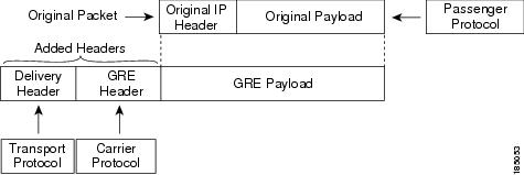
GRE Tunnels

You can use generic routing encapsulation (GRE) as the carrier protocol for a variety of passenger protocols.

The following figure shows the IP tunnel components for a GRE tunnel. The original passenger protocol packet becomes the GRE payload and the device adds a GRE header to the packet. The device then adds the transport protocol header to the packet and transmits it.

Figure 1. GRE PDU


Point-to-Point IP-in-IP Tunnel Encapsulation and Decapsulation

The point-to-point IP-in-IP encapsulation and decapsulation is a type of tunnel that you can create to send encapsulated packets from a source tunnel interface to a destination tunnel interface. This type of tunnel will carry both inbound and outbound traffic.

From Cisco NX-OS Release 10.4(1)F, IPv4 tunnel is supported on GRE and IPv6 traffic can be encapsulated within GRE IPv4.


Note


Beginning with Cisco NX-OS Release 10.3(3)F, the selection of GRE or IP-in-IP tunnel destination based on the PBR policy is supported.


Note


IP-in-IP tunnel encapsulation and decapsulation is not supported on Cisco Nexus 9500 Series switches with N9K-X9636C-R, N9K-X9636Q-R, N9K-X9636C-RX line cards.


Note


IP-in-IP tunnel encapsulation and decapsulation is not supported on a vPC setup on Cisco Nexus 9300-EX, 9300-FX, 9300-GX and Nexus 9500 platform switches.


Multi-Point IP-in-IP Tunnel Decapsulation

The multi-point IP-in-IP decapsulate-any is a type of tunnel that you can create to decapsulate packets from any number of IP-in-IP tunnels to one tunnel interface. This tunnel will not carry any outbound traffic. However, any number of remote tunnel endpoints can use a tunnel configured this way as their destination.

Path MTU Discovery

Path maximum transmission unit (MTU) discovery (PMTUD) prevents fragmentation in the path between two endpoints by dynamically determining the lowest MTU along the path from the packet's source to its destination. PMTUD reduces the send MTU value for the connection if the interface receives information that the packet would require fragmentation.

When you enable PMTUD, the interface sets the Don't Fragment (DF) bit on all packets that traverse the tunnel. If a packet that enters the tunnel encounters a link with a smaller MTU than the MTU value for the packet, the remote link drops the packet and sends an ICMP message back to the sender of the packet. This message indicates that fragmentation was required (but not permitted) and provides the MTU of the link that dropped the packet.


Note


PMTUD on a tunnel interface requires that the tunnel endpoint can receive ICMP messages generated by devices in the path of the tunnel. Check that ICMP messages can be received before using PMTUD over firewall connections.


High Availability

IP tunnels support stateful restarts. A stateful restart occurs on a supervisor switchover. After the switchover, Cisco NX-OS applies the runtime configuration after the switchover.

Prerequisites for IP Tunnels

IP tunnels have the following prerequisites:

  • You must be familiar with TCP/IP fundamentals to configure IP tunnels.

  • You are logged on to the switch.

  • You must enable the tunneling feature in a device before you can configure and enable any IP tunnels.

Guidelines and Limitations

IP tunnels have the following configuration guidelines and limitations:

  • Beginning with Cisco NX-OS Release 9.3(3):

    • Total number of 16 GRE/IPIP tunnels are supported on Cisco Nexus 9200, 9300-EX/FX/FX2 switches, and 9500 switches with 9700-EX/FX line cards.

    • More than 1 and up to 16 IPIP Decap-any tunnels are supported - 1 decap-any tunnel per VRF. This is supported on Cisco Nexus 9200, and 9300-EX/FX/FX2 platforms.

    • VRF membership of the interface, where IPIP/GRE encapsulated packets are ingressing on the terminating node, should match with the tunnel transport VRF for tunnel to correctly terminate the packets.

    • The IPIP/GRE packet coming on a non default VRF may get terminated by a tunnel in default VRF if the packet outer header matches with the tunnel source and the tunnel destination.

  • Beginning with Cisco NX-OS Release 9.3(5), the following features are supported on N9K-C9316D-GX, N9K-C93600CD-GX and N9K-C9364C-GX switches:

    • A total number of 16 GRE/IPIP tunnels.

    • More than 1 and upto 16 IPIP Decap-any tunnels are supported -- 1 decap-any tunnel per VRF.

  • You must configure multiple GRE or IP-in-IP tunnels that use the same outer transport VRF (tunnel use-vrf) with a unique tunnel destination IP, per tunnel in these platforms:

    • N9K-X9736C-FX, N9K-X9736Q-FX, N9K-X9788TC-FX, N9K-C93180YC-FXN9K-C93108TC-FX, N9K-C9348GC-F, N9K-C9348GC-FXP, N9K-C9358GY-FXP, N9K-X9732C-FX,

    • N9K-C9336C-FX2-E, N9K-C93216TC-FX2, N9K-C93360YC-FX2, N9K-C93240YC-FX2-Z, N9K-C93240YC-FX2,N9K-C9336C-FX2

    • N9K-C9316D-GX, N9K-C93600CD-GX, N9K-C9364C-GX, N9K-X9716D-GX,

    • N9K-X9736C-FX3, N9K-C93180YC-FX3S, N9K-C93180YC-FX3, N9K-C93108TC-FX3P,N9K-C9348GC-FX3, N9K-C9348GC-FX3PH, N9K-C93108TC-FX3, N9K-C92348GC-FX3

    • N9K-C9364D-GX2A, N9K-C9332D-GX2B, N9K-C9348D-GX2A, N9K-C9408

    • N9K-C9332D-H2R, N9K-C9364C-H1, N9K-C93400LD-H1

  • On all Nexus platforms, you must configure multiple GRE or IP-in-IP tunnels that use the same outer transport VRF (tunnel use-vrf) with unique tunnel source IP and tunnel destination IP, per tunnel.

  • Nexus 9000 switches do not support the coexistence of IP tunnels with FC/FCOE traffic. Bringing up an IP tunnel on a switch with FC/FCOE traffic results in that traffic being dropped.

  • From Cisco NX-OS Release 10.4(1)F, you can configure loopback IP address as tunnel source IP address using the tunnel source CLI command with loopback interface.

  • The show commands with the internal keyword are not supported.

  • Cisco NX-OS supports only the following protocols:

    • IPv4 passenger protocol.

    • GRE carrier protocol.

  • Beginning with Cisco NX-OS Release 9.3(3), the maximum number of supported GRE and IP-in-IP regular tunnels is 16.

  • IP tunnels do not support access control lists (ACLs) or QoS policies.

  • Cisco NX-OS supports the GRE header defined in IETF RFC 2784. Cisco NX-OS does not support tunnel keys and other options from IETF RFC 1701.

  • Cisco NX-OS does not support GRE tunnel keepalives.

  • All unicast routing protocols are supported by IP tunnels.

  • The IP tunnel interface cannot be configured to be a span source or destination.

  • Beginning with Cisco NX-OS Release 10.3(3)F, the selection of GRE or IP-in-IP tunnel destination based on the PBR policy is supported.

  • BGP adjacency over tunnel is not supported in a scenario where the tunnel interface and tunnel source are in same VRF (example: VRF-A) and tunnel destination is reachable with route-leak from opposite end (example: via VRF-B)

  • GRE tunnels does not support RACLs.

  • When setting up a GREv6 or IP-in-IP tunnel, you cannot use different VRFs for the tunnel interface and the tunnel destination. Both must use the same VRF for the tunnel to work properly.You need to use the same VRF for the tunnel interface and the tunnel destination.

    For GREv4, configuring tunnel interface VRF member that is different from the tunnel use-vrf is supported.

    switch# interface tunnel X
    vrf member INNER-VRF
    tunnel use-vrf TRANSPORT-VRF
  • GRE tunnels supports only limited traffic (ingress or egress) counters.

  • Layer 3 FEX interfaces not are allowed as tunnel source and/or destination

  • Double encapsulation is not allowed on GRE tunnels.

  • BFD is not supported on GRE tunnels.

  • On Cisco Nexus N9K-C9300-GX platforms, GRE/IPinIP tunnel interfaces cannot co-exist with Dot1Q tagged L2 bcast or 1Q tagged L2/L3 mcast transit traffic. When you configure feature tunnel on Cisco Nexus N9300-GX platform, the following warning is displayed and you get a syslog message warning you. You should not configure feature tunnel if you have Dot1Q tagged L2 bcast or 1Q tagged L2/L3 mcast transit traffic on the device.

    N9300-GX(config)# feature tunnel
    WARN:GRE/IPinIP cannot coexist with 1Q tagged L2 bcast or 1Q tagged L2/L3 mcast transit packets on this
    platform
    N9300-GX(config)#
    N9300-GX(config)# show logging logfile
    2019 Dec 12 00:41:08 N9300-GX %TUNNEL-2-TRAFFIC_WARNING: GRE/IPinIP cannot coexist with 1Q
    tagged L2 bcast or 1Q tagged L2/L3 mcast transit packets on this platform
    N9300-GX(config)#
  • The feature feature tunnel on the Cisco Nexus 9000 switches cannot co-exist with the VXLAN feature, feature nv overlay.

  • Cisco Nexus 9200, 9300-EX, 9300-FX, 9300-FX2 series switches and Cisco Nexus 9500 platform switches with 9700-EX/FX line cards may not have multiple tunnel interfaces in a single VRF that are sourced from or destined to the same IP address. For example, a device may not have tunnel 0 and tunnel 1 interfaces in the default VRF that are sourced from the same IP address or interface.

  • Cisco Nexus 9300-EX, 9300-FX, 9300-GX and Nexus 9500 platform switches in vPC can act as GRE Tunnel endpoints for their respective tunnels. However, the tunnel destination can not be through a vPC.

  • Beginning with Cisco NX-OS Release 10.3(3)F, the PBR policy on a tunnel interface is supported only for gre ip, ipip ip, and ipip decapsulate-any ip modes on Cisco Nexus 9300-FX2/FX3/GX/GX2 platform switches .

  • Beginning with Cisco NX-OS Release 10.4(1)F, GRE tunnel is supported on Cisco Nexus 9332D-H2R switch.

  • Beginning with Cisco NX-OS Release 10.4(2)F, GRE tunnel is supported on Cisco Nexus 93400LD-H1 switch.

  • IP tunnels are not supported on Cisco Nexus 9300-FX or Cisco Nexus 9300-FX2 switches if FC or FCOE is configured.

Default Settings

The following table lists the default settings for IP tunnel parameters.

Table 1. Default IP Tunnel Parameters

Parameters

Default

Path MTU discovery age timer

10 minutes

Path MTU discovery minimum MTU

64

Tunnel feature

Disabled

Configuring IP Tunnels


Note


If you are familiar with the Cisco IOS CLI, be aware that the Cisco NX-OS commands for this feature might differ from the Cisco IOS commands that you would use.


Enabling Tunneling

You must enable the tunneling feature before you can configure any IP tunnels.

SUMMARY STEPS

  1. configure terminal
  2. feature tunnel
  3. exit
  4. show feature
  5. copy running-config startup-config

DETAILED STEPS

  Command or Action Purpose

Step 1

configure terminal

Example:

switch# configure terminal
switch(config)#

Enters global configuration mode.

Step 2

feature tunnel

Example:

switch(config)# feature tunnel
switch(config-if)#

Allows the creation of a new tunnel interface.

To disable the tunnel interface feature, use the no form of this command.

Note


The feature tunnel command may break the multicast functionality if multicast heavy template is enforced.

Step 3

exit

Example:

switch(config-if)# exit
switch#

Exits the interface mode and returns to the configuration mode.

Step 4

show feature

Example:

switch(config-if)# show feature

(Optional) Displays information about the features enabled on the device.

Step 5

copy running-config startup-config

Example:

switch(config-if)# copy running-config
startup-config

(Optional) Saves this configuration change.

Creating a Tunnel Interface

You can create a tunnel interface and then configure this logical interface for your IP tunnel.


Note


Cisco NX-OS supports a maximum of 8 IP tunnels.


Note


Use the no interface tunnel command to remove the tunnel interface and all associated configuration.

Command

Purpose

no interface tunnel number

Example:

switch(config)# no interface tunnel 1

Deletes the tunnel interface and the associated configuration.

description string

Example:

switch(config-if)# description GRE tunnel

Configures a description for the tunnel.

mtu value

Example:

switch(config-if)# mtu 1400

Sets the MTU of IP packets sent on an interface.

tunnel ttl value

Example:

switch(config-if)# tunnel ttl 100

Sets the tunnel time-to-live value. The range is from 1 to 255.


Note


Configuring an GREv6 or IP-in-IP tunnel that uses a tunnel interface VRF that is different from the use-vrf for the tunnel destination is not supported. You need to use the same VRF for a tunnel interface and the tunnel destination. For GREv4, configuring tunnel interface VRF that is different from the use-vrf for tunnel is supported.


Before you begin

You can configure the tunnel source and the tunnel destination in different VRFs. Ensure that you have enabled the tunneling feature.

SUMMARY STEPS

  1. configure terminal
  2. interface tunnel number
  3. tunnel mode {gre ip | ipip {ip | decapsulate-any}}
  4. tunnel source {ip-address |interface-name}
  5. tunnel destination {ip-address |host-name}
  6. tunnel use-vrf vrf-name
  7. show interfaces tunnel number
  8. copy running-config startup-config

DETAILED STEPS

  Command or Action Purpose

Step 1

configure terminal

Example:

switch# configure terminal
switch(config)#

Enters global configuration mode.

Step 2

interface tunnel number

Example:

switch(config)# interface tunnel 1
switch(config-if)#

Creates a new tunnel interface.

Step 3

tunnel mode {gre ip | ipip {ip | decapsulate-any}}

Sets this tunnel mode to GRE, ipip, or ipip decapsulate-only.

The gre and ip keywords specify that GRE encapsulation over IP will be used.

The ipip keyword specifies that IP-in-IP encapsulation will be used. The optional decapsulate-any keyword terminates IP-in-IP tunnels at one tunnel interface. This keyword creates a tunnel that will not carry any outbound traffic. However, remote tunnel endpoints can use a tunnel configured as their destination.

Step 4

tunnel source {ip-address |interface-name}

Example:

switch(config-if)# tunnel source
ethernet 1/2

Configures the source address for this IP tunnel. The source can be specified by IP address or logical interface name.

Step 5

tunnel destination {ip-address |host-name}

Example:

switch(config-if)# tunnel destination
192.0.2.1

Configures the destination address for this IP tunnel. The destination can be specified by IP address or logical host name.

Step 6

tunnel use-vrf vrf-name

Example:

switch(config-if)# tunnel use-vrf blue

(Optional) Uses the configured VRF to look up the tunnel IP destination address.

Step 7

show interfaces tunnel number

Example:

switch# show interfaces tunnel 1

(Optional) Displays the tunnel interface statistics.

Step 8

copy running-config startup-config

Example:

switch(config-if)# copy running-config
startup-config

(Optional) Saves this configuration change.

Example

This example shows how to create a tunnel interface

switch# configure terminal
switch(config)# interface tunnel 1
switch(config-if)# tunnel source ethenet 1/2
switch(config-if)# tunnel destination 192.0.2.1
switch(config-if)# copy running-config startup-config

Configuring a Tunnel Interface

You can set a tunnel interface to GRE tunnel mode, ipip mode, or ipip decapsulate-only mode. GRE mode is the default tunnel mode. .

The tunnel source direct and tunnel mode ipv6ipv6 decapsulate-any CLI commands are supported on Cisco Nexus 9000 Series switches.

Before you begin

Ensure that you have enabled the tunneling feature.

SUMMARY STEPS

  1. configure terminal
  2. interface tunnel number
  3. tunnel mode {gre ip | ipip | {ip | decapsulate-any}}
  4. show interfaces tunnel number
  5. mtu value
  6. copy running-config startup-config

DETAILED STEPS

  Command or Action Purpose

Step 1

configure terminal

Example:

switch# configure terminal
switch(config)#

Enters global configuration mode.

Step 2

interface tunnel number

Example:

switch(config)# interface tunnel 1
switch(config-if)#

Creates a new tunnel interface.

Step 3

tunnel mode {gre ip | ipip | {ip | decapsulate-any}}

Sets this tunnel mode to GRE, ipip, or ipip decapsulate-only.

The gre and ip keywords specify that GRE encapsulation over IP will be used.

The ipip keyword specifies that IP-in-IP encapsulation will be used. The optional decapsulate-any keyword terminates IP-in-IP tunnels at one tunnel interface. This keyword creates a tunnel that will not carry any outbound traffic. However, remote tunnel endpoints can use a tunnel configured as their destination.

Step 4

show interfaces tunnel number

Example:

switch(config-if)# show interfaces tunnel 1

(Optional) Displays the tunnel interface statistics.

Step 5

mtu value

Sets the maximum transmission unit (MTU) of IP packets sent on an interface.

The range is from 64 to 9192 units.

Step 6

copy running-config startup-config

Example:

switch(config-if)# copy running-config
startup-config

(Optional) Saves this configuration change.

Example

This example shows how to create the tunnel interface to GRE:

switch# configure terminal
switch(config)# interface tunnel 1
switch(config-if)# tunnel mode gre ip
switch(config-if)# copy running-config startup-config

This example shows how to create an ipip tunnel:

switch# configure terminal
switch(config)# interface tunnel 1
switch(config-if)# tunnel mode ipip
switch(config-if)# mtu 1400
switch(config-if)# copy running-config startup-config
switch(config-if)# no shut

Configuring a GRE Tunnel

You can set a tunnel interface to GRE tunnel mode.


Note


Cisco NX-OS supports only the GRE protocol for IPV4 over IPV4.


Before you begin

Ensure that you have enabled the tunneling feature.

SUMMARY STEPS

  1. configure terminal
  2. interface tunnel number
  3. tunnel mode gre ip
  4. show interfaces tunnel number
  5. copy running-config startup-config

DETAILED STEPS

  Command or Action Purpose

Step 1

configure terminal

Example:

switch# configure terminal
switch(config)#

Enters global configuration mode.

Step 2

interface tunnel number

Example:

switch(config)# interface tunnel 1
switch(config-if)#

Creates a new tunnel interface.

Step 3

tunnel mode gre ip

Example:

switch(config-if)# tunnel mode gre ip

Sets this tunnel mode to GRE.

Step 4

show interfaces tunnel number

Example:

switch(config-if)# show interfaces tunnel 1

(Optional) Displays the tunnel interface statistics.

Step 5

copy running-config startup-config

Example:

switch(config-if)# copy running-config
startup-config

(Optional) Saves this configuration change.

Enabling Path MTU Discovery

Use the tunnel path-mtu discovery command to enable path MTU discovery on a tunnel.

SUMMARY STEPS

  1. tunnel path-mtu-discovery age-timer min
  2. tunnel path-mtu-discovery min-mtu bytes

DETAILED STEPS

  Command or Action Purpose

Step 1

tunnel path-mtu-discovery age-timer min

Example:

switch(config-if)# tunnel path-mtu-discovery age-timer 25

Enables Path MTU Discovery (PMTUD) on a tunnel interface.

  • min—Number of minutes. The range is from 10 to 30. The default is 10.

Step 2

tunnel path-mtu-discovery min-mtu bytes

Example:

switch(config-if)# tunnel path-mtu-discovery min-mtu 1500

Enables Path MTU Discovery (PMTUD) on a tunnel interface.

  • bytes—Minimum MTU recognized.

    The range is from 64 to 9192. The default is 64.

Assigning VRF Membership to a Tunnel Interface

You can add a tunnel interface to a VRF.

Before you begin

Ensure that you have enabled the tunneling feature.

Assign the IP address for a tunnel interface after you have configured the interface for a VRF.

SUMMARY STEPS

  1. configure terminal
  2. interface tunnel number
  3. vrf member vrf-name
  4. ip address ip-prefix/length
  5. show vrf [vrf-name] interface interface-type number
  6. copy running-config startup-config

DETAILED STEPS

  Command or Action Purpose

Step 1

configure terminal

Example:

switch# configure terminal
switch(config)#

Enters global configuration mode.

Step 2

interface tunnel number

Example:

switch(config)# interface tunnel 0
switch(config-if)#

Enters interface configuration mode.

Step 3

vrf member vrf-name

Example:

switch(config-if)# vrf member RemoteOfficeVRF

Adds this interface to a VRF.

Step 4

ip address ip-prefix/length

Example:

switch(config-if)# ip address 192.0.2.1/16

Configures an IP address for this interface. You must do this step after you assign this interface to a VRF.

Step 5

show vrf [vrf-name] interface interface-type number

Example:

switch(config-vrf)# show vrf Enterprise
interface tunnel 0

(Optional) Displays VRF information.

Step 6

copy running-config startup-config

Example:

switch# copy running-config startup-config

(Optional) Saves this configuration change.

Example

This example shows how to add a tunnel interface to the VRF:

switch# configure terminal
switch(config)# interface tunnel 0
switch(config-if)# vrf member RemoteOfficeVRF
switch(config-if)# ip address 209.0.2.1/16
switch(config-if)# copy running-config startup-config

Verifying the IP Tunnel Configuration

To verify the IP tunnel configuration information, perform one of the following tasks:

Command

Purpose

show interface tunnel number

Displays the configuration for the tunnel interface (MTU, protocol, transport, and VRF). Displays input and output packets, bytes, and packet rates.

show interface tunnel number brief

Displays the operational status, IP address, encapsulation type, and MTU of the tunnel interface.

show interface tunnel number counters

Displays interface counters of input/output packets.

Note


The byte count displayed with the interface counters include the internal header size.

show interface tunnel number description

Displays the configured description of the tunnel interface.

show interface tunnel number status

Displays the operational status of the tunnel interface.

show interface tunnel number status err-disabled

Displays the error disabled status of the tunnel interface.

Configuration Examples for IP Tunneling

The following example shows a simple GRE tunnel. Ethernet 1/2 is the tunnel source for router A and the tunnel destination for router B. Ethernet interface 2/1 is the tunnel source for router B and the tunnel destination for router A.

Router A:


feature tunnel
interface tunnel 0
ip address 209.165.20.2/8
tunnel source ethernet 1/2
tunnel destination 192.0.2.2
tunnel mode gre ip
tunnel path-mtu-discovery 25 1500

interface ethernet 1/2
ip address 192.0.2.55/8

Router B:


feature tunnel
interface tunnel 0
ip address 209.165.20.1/8
tunnel source ethernet 2/1
tunnel destination 192.0.2.55
tunnel mode gre ip

interface ethernet 2/1
ip address 192.0.2.2/8

Related Documents

Related Topic

Document Title

IP Tunnel commands

Cisco Nexus 9000 Series NX-OS Interfaces Command Reference