Setting Up the Multi-Fabric Orchestration

Example Topology for Multi-Fabric Orchestration

The following figure shows one of the supported topologies that could be used for multi-fabric orchestration, and is used in this document to demonstrate the steps required for orchestrating VXLAN Multi-Site connectivity using NDFC and NDO.

In this deployment procedure, you will configure VXLAN Multi-Site connectivity between the fabrics managed by the same NDFC or by different NDFCs, and the configurations that you will make in each of these connectivity areas. The overall configuration steps are as follows:

Set Up the VXLAN Fabrics in First and Second NDFC Instances

In the figure shown in Example Topology for Multi-Fabric Orchestration, there are four VXLAN fabrics:

  • VXLAN-Site1 and VXLAN-Site2 fabrics, managed by the first NDFC instance (NDFC1)

  • VXLAN-Site3 and VXLAN-Site4 fabrics, managed by the second NDFC instance (NDFC2)

In this section, you will set up the two VXLAN fabrics within each NDFC instance.


Note


For more detailed information for these NDFC procedures, see:


Complete the procedures in the following sections to set up the two VXLAN fabrics in each NDFC.

Create the VXLAN Fabrics in the First NDFC Instance

In this procedure, you will be configuring the part of the example topology highlighted below.

Complete the procedures in the following sections to configure the VXLAN fabrics in the first NDFC instance.

Procedure


Step 1

Log into the Nexus Dashboard where you have the first instance of NDFC installed.

Step 2

Log into your NDFC account.

Step 3

Navigate to LAN > Fabrics.

The LAN Fabrics window appears.

Step 4

Click Actions > Create Fabric.

The Create Fabric window appears.

Step 5

Begin the process of creating the first VXLAN fabric in the first NDFC instance using the Data Center VXLAN EVPN template.

  1. In the Fabric Name field, enter a unique name for the first VXLAN fabric.

    For example, VXLAN-Site1.

  2. In the Pick a Template area, click Choose Template.

    The Select Fabric Template window appears.
  3. Locate and click the Data Center VXLAN EVPN template.

  4. Click Select.

Step 6

Complete the necessary general VXLAN fabric parameter configurations.

The following parameter tabs in the Data Center VXLAN EVPN template must be completed:

  • General Parameters

  • Replication

  • VPC

  • Protocols

Note


Only the BGP ASN field is mandatory. The rest of the fields in General Parameters and the other tabs are pre-populated by NDFC with default values that can be changed, as required.

Complete the VXLAN fabric configurations in those parameter tabs as you normally would. See Cisco NDFC-Fabric Controller Configuration Guide, Release 12.1.2 or later, for more information.

For example, using the information in the example topology, you would enter 65100 in the BGP ASN field in the General Parameters page.

Step 7

Click Save when you have completed the necessary configurations in the Create Fabric window for the first VXLAN fabric.

You are returned to the LAN Fabrics window, with the first VXLAN fabric that you just created displayed.

Step 8

Repeat Step 3 through Step 7 to create a second VXLAN fabric in the first NDFC instance.

  • In the Fabric Name field in the Create Fabric window, enter a unique name for the second VXLAN fabric in the first NDFC instance (for example, VXLAN-Site2).

  • In the General Parameters page in the Create Fabric window, enter a unique BGP Autonomous System Number (ASN) in the BGP ASN field for this fabric.

    For example, using the information in the example topology, you would enter 65200 in the BGP ASN field in the General Parameters page.

When you have finished creating the second VXLAN fabric, you should now have two VXLAN fabrics (VXLAN-Site1 and VXLAN-Site2) that are being managed by the first NDFC instance.


Create the VXLAN Fabrics in the Second NDFC Instance

In this procedure, you will be configuring the part of the example topology highlighted below.

For these procedures, follow the same procedures that you used to create the VXLAN fabrics in the first NDFC instance. Create two VXLAN fabrics in the second NDFC instance using the same instructions that were provided in Create the VXLAN Fabrics in the First NDFC Instance:

  • First VXLAN fabric in second NDFC instance: VXLAN-Site3

  • Second VXLAN fabric in second NDFC instance: VXLAN-Site4

Once you have completed the procedures to fully configure the VXLAN fabrics in the second NDFC instance, onboard the NDFC sites into Nexus Dashboard and Nexus Dashboard Orchestrator using the procedures provided in Onboard the NDFC Sites into ND and NDO.

Configure an NDFC External Fabric

Configuring an NDFC external fabric is only required if you are building Route Server-based VXLAN Multi-Site connectivity using NDO. You can create this external fabric on either of the NDFCs, or you can use a separate NDFC instance. Configure an external fabric that contains the Route Server in this case. See Understanding BGP Peering Type Options for more information on the Route Server option as the BGP peering type.

For instructions on configuring an external fabric, see:

When configuring an external fabric that contains the Route Server:

  • You should not enable the Fabric Monitor Mode option for this use case.

  • Onboard the Route Server device to this external fabric and set the role as Core.

Onboard the NDFC Sites into ND and NDO

Before you begin

Set up the VXLAN fabrics in the first and second NDFC instances using the procedures provided in Set Up the VXLAN Fabrics in First and Second NDFC Instances.

Procedure


Step 1

Log into Nexus Dashboard (ND) cluster where NDO is installed.

Step 2

In Nexus Dashboard, click Sites > Add Site.

The Add Site page appears.

Step 3

Click the NDFC box in the Site Type area.

Step 4

Enter the necessary information to add the VXLAN fabrics from the first NDFC instance that were created in the section Create the VXLAN Fabrics in the First NDFC Instance.

  • In the Hostname/IP Address field, enter the data interface IP address for the first NDFC instance.

  • In the Username and Password field, enter the username and password login information for the first NDFC instance.

Step 5

Click Select Sites.

The two VXLAN fabrics from the first NDFC instance in Create the VXLAN Fabrics in the First NDFC Instance are displayed (VXLAN-Site1 and VXLAN-Site2).

Step 6

Click the boxes next to the two VXLAN fabrics, then click Select.

You are returned to the Add Site page.

Step 7

(Optional) In the Sites area in the Add Site page, on the line for each VXLAN fabric that you just added, click the location icon and drop a pin on the map to designate the geolocation on the world map for the each VXLAN fabric.

Step 8

Click Save.

You are returned to the Sites in Nexus Dashboard.

Step 9

Add the two VXLAN fabrics from the second NDFC instance in Nexus Dashboard.

Repeat Step 2 through Step 8 to add the second NDFC instance and the two VXLAN fabrics from Create the VXLAN Fabrics in the Second NDFC Instance (VXLAN-Site3 and VXLAN-Site4).

Step 10

If you are using a route server as the BGP peering type, add the external fabric that contains the route server.

See Understanding BGP Peering Type Options for more information on the route server option as the BGP peering type.

Step 11

In Nexus Dashboard, click Sites again.

You should see all four VXLAN fabrics displayed in the Sites page:

  • The two VXLAN fabrics from the first NDFC instance:

    • VXLAN-Site1

    • VXLAN-Site2

  • The two VXLAN fabrics from the second NDFC instance:

    • VXLAN-Site3

    • VXLAN-Site4

If you are using a route server as the BGP peering type, you will also see the external fabric that contains the route server.

Step 12

Access Nexus Dashboard Orchestrator (NDO).

In Nexus Dashboard, click Services > Installed Services, then click Open on the Nexus Dashboard Orchestrator option.

Step 13

In NDO, click Sites.

Step 14

From NDO, start managing all four VXLAN fabrics.

Perform the following steps for each site in NDO:

  1. Under the State column, change the state from Unmanaged to Managed.

  2. Under the Name column, for each managed site, provide a site ID that is unique (a site ID that does not conflict with site IDs for any other site being managed through this NDO). You could use the BGP ASN number that you assigned to each fabric as the site ID number, if desired.

    For example:

    • 65100 for the site ID for VXLAN-Site1

    • 65200 for the site ID for VXLAN-Site2

    • 65300 for the site ID for VXLAN-Site3

    • 65400 for the site ID for VXLAN-Site4

    If you are using a route server as the BGP peering type, for the external fabric that contains the route server, also change the state from Unmanaged to Managed and provide a unique site ID for that site.


What to do next

Complete the site-to-site connectivity between the sites using the procedures provided in Complete VXLAN Multi-Site Connectivity Between the NDFC Sites.

Complete VXLAN Multi-Site Connectivity Between the NDFC Sites

Follow the procedures in the following sections to complete the site-to-site connectivity between the NDFC sites.

Complete the Necessary Control Plane Configurations

Before you begin

Onboard the NDFC sites in ND and NDO using the procedures provided in Onboard the NDFC Sites into ND and NDO.

Procedure


Step 1

In NDO, navigate to Infrastructure > Site Connectivity.

At this point, you will see the sites on the world map, with a red link connecting those sites, which means that there is no connectivity between the sites at this point.

Step 2

In the upper right area in the Site Connectivity window, click Configure.

The General Settings area of the Site Connectivity window appears.

Step 3

In the General Settings area, click the Control Plane Configuration tab, then make the necessary configurations in this page.

Note


These general BGP settings apply to the use of BGP for both underlay and overlay connectivity and normally should not be changed, with the exception of the BGP Peering Type option in the next step that only applies to overlay peering.

Step 4

For overlay connectivity between the NDFC sites, make the appropriate selection in the BGP Peering Type field in the BGP area:

See Understanding BGP Peering Type Options for more information on the different BGP peering types.

  • full-mesh: Select this option if you have a small number of sites (for example, two or three sites). Do not use this option if you have a larger number of sites, since you will be creating separate BGP peerings when you create direction connections between BGWs in different sites using this option, which does not scale well.

    Go to Step 5 if you select the full-mesh option.

  • route-server: This option uses the route server model, where the BGW of one site forms the BGP peering with the route server, and the route server forms the peering with the remaining sites. This option is applicable if you have a larger number of sites (for example, greater than two or three sites).

    If you select route-server as the BGP peering type, complete the following procedures to configure the route server:

  1. Click Add Route Server to add the route server.

    The Add Route Server window appears.

  2. Under Site, select the external fabric that you onboarded in Onboard the NDFC Sites into ND and NDO.

  3. In the Core Router Device field, select the route server that you configured in the external fabric.

  4. In the Interface field, select the loopback interface that you configured in the external fabric.

  5. Click Ok.

  6. Go to Step 5.

Step 5

Define any remaining parameters in the Control Plane Configuration page.

For the remaining tabs in the General Settings window:

  • You can enable the CloudSec Control option, if desired.

    CloudSec is a type of encryption that might be used with VXLAN EVPN Multi-site configurations.

  • In the Data Path area, select VXLAN in the Encapsulation Type field.

  • You can leave the default values in the NDFC Settings tab as-is, if they work for your configuration.


Configure Inter-Site Connectivity

The procedures for configuring inter-site connectivity differs, depending on the choice that you made in the BGP Peering Type field in Complete the Necessary Control Plane Configurations:

Configure Inter-Site Connectivity for Full-Mesh BGP Peering Type Configurations

In this section, you will configure inter-site connectivity for full-mesh BGP peering type configurations, where you will define the Multi-Site VIP and you will add the port for each BGW device in each VXLAN fabric site.

Procedure

Step 1

In the left pane under General Settings: Sites, click the first VXLAN fabric site (VXLAN-Site 1).

Step 2

In the right pane, under Inter-Site Connectivity, define the Multi-Site VIP in the Multi-Site VIP field for the first VXLAN fabric site.

This Multi-Site VIP will be configured on all the BGW devices in this site. You can click Auto Allocate or you can explicitly define the IP address for the Multi-Site VIP.

Step 3

Leaving the first VXLAN fabric site selected in the left pane, in the middle pane, click the first BGW device.

Step 4

In the right pane, click Add Port.

Step 5

Enter the necessary information in this page.

Define the port parameters in this page.

  • In the Ethernet Port ID field, select the interface on the BGW device on the first VXLAN fabric site (VXLAN-Site 1) that connects to the BGW device of the second VXLAN fabric site (VXLAN-Site 2).

  • In the IP Address field, enter the IP address for this interface. Later in these procedures, Nexus Dashboard Orchestrator will configure this IP address for this interface on the BGW device residing in this VXLAN fabric.

  • In the Remote Address field, enter the IP address of the gigabit 4 interface of the BGW device on the second VXLAN fabric site (VXLAN-Site 2).

  • In the Remote ASN field, enter the ASN for the BGW device on the second VXLAN fabric site (VXLAN-Site 2). For example, for this example use case, we would enter 65200 as the ASN for the BGW device on the second VXLAN fabric site.

Step 6

Click Save.

You are returned to the Site Connectivity page.

Step 7

Repeat Step 3 through Step 6 to configure additional ports to connect additional BGW devices in the first VXLAN fabric to the BGW devices on the second VXLAN fabric site.

At this point in the process, you have configured the following port:

BGW device on VXLAN-Site 1 → BGW device on VXLAN-Site 2

However, because you have four VXLAN fabrics that need to connect to each other in this use case, you also need to configure additional ports on the BGW device on VXLAN-Site 1:

  1. Leaving the VXLAN-Site 1 site selected under General Settings: Sites and the spine device selected in the middle pane, click Add Port again, then repeat Step 4 through Step 6 to connect to the BGW device on the third VXLAN fabric site (VXLAN-Site 3).

  2. Leaving the VXLAN-Site 1 site selected under General Settings: Sites and the spine device selected in the middle pane, click Add Port again, then repeat Step 4 through Step 6 to connect to the BGW device on the fourth VXLAN fabric site (VXLAN-Site 4).

At this point in the process, you have now configured the necessary ports to connect the BGW device on the first VXLAN fabric to the BGW devices on the remaining VXLAN fabric sites:

  • BGW device on VXLAN-Site 1 → BGW device on VXLAN-Site 2

  • BGW device on VXLAN-Site 1 → BGW device on VXLAN-Site 3

  • BGW device on VXLAN-Site 1 → BGW device on VXLAN-Site 4

Note


If you have multiple BGWs in the first VXLAN fabric site, repeat Step 3 through Step 7 to add the necessary ports for each of these additional BGWs.

Step 8

When you have completed the process of configuring the necessary ports to connect the BGW device on the first VXLAN fabric to the BGW devices on the remaining VXLAN fabric sites, repeat these steps for the second VXLAN fabric.

  1. In the left pane under General Settings: Sites, click the second VXLAN fabric site (VXLAN-Site 2).

  2. Define the Multi-Site VIP for the second VXLAN fabric site using Step 1 through Step 2.

  3. Repeat Step 3 through Step 7 to configure the necessary ports to connect the BGW device on the second VXLAN fabric to the BGW devices on the remaining VXLAN fabric sites:

    • BGW device on VXLAN-Site 2 → BGW device on VXLAN-Site 1

    • BGW device on VXLAN-Site 2 → BGW device on VXLAN-Site 3

    • BGW device on VXLAN-Site 2 → BGW device on VXLAN-Site 4

Step 9

When you have completed the process of configuring the necessary ports to connect the BGW device on the second VXLAN fabric to the BGW devices on the remaining VXLAN fabric sites, repeat these steps for the third VXLAN fabric.

  1. In the left pane under General Settings: Sites, click the third VXLAN fabric site (VXLAN-Site 3).

  2. Define the Multi-Site VIP for the third VXLAN fabric site using Step 1 through Step 2.

  3. Repeat Step 3 through Step 7 to configure the necessary ports to connect the BGW device on the third VXLAN fabric to the BGW devices on the remaining VXLAN fabric sites:

    • BGW device on VXLAN-Site 3 → BGW device on VXLAN-Site 1

    • BGW device on VXLAN-Site 3 → BGW device on VXLAN-Site 2

    • BGW device on VXLAN-Site 3 → BGW device on VXLAN-Site 4

Step 10

When you have completed the process of configuring the necessary ports to connect the BGW device on the third VXLAN fabric to the BGW devices on the remaining VXLAN fabric sites, repeat these steps for the fourth VXLAN fabric.

  1. In the left pane under General Settings: Sites, click the fourth VXLAN fabric site (VXLAN-Site 4).

  2. Define the Multi-Site VIP for the fourth VXLAN fabric site using Step 1 through Step 2.

  3. Repeat Step 3 through Step 7 to configure the necessary ports to connect the BGW device on the fourth VXLAN fabric to the BGW devices on the remaining VXLAN fabric sites:

    • BGW device on VXLAN-Site 4 → BGW device on VXLAN-Site 1

    • BGW device on VXLAN-Site 4 → BGW device on VXLAN-Site 2

    • BGW device on VXLAN-Site 4 → BGW device on VXLAN-Site 3

Step 11

Once you have completed these configurations for all four VXLAN fabric sites, click Deploy.

This step will cause NDO to generate all the required configurations to build the VXLAN Multi-Site between the sites, which are then pushed to the respective NDFCs using the REST APIs.


What to do next
Go to Configure the Necessary VRF and Network.

Configure Inter-Site Connectivity for Route Server BGP Peering Type Configurations

In this section, you will configure inter-site connectivity for route-server BGP peering type configurations, where you will add the ports on the Route Server in the external fabric site connecting to the BGW of each VXLAN fabric.

Procedure

Step 1

In the left pane under General Settings: Sites, click the external fabric site.

Step 2

In the middle pane, click the router device that is used with the Route Server in the external fabric site.

Step 3

In the right pane, click Add Port.

Step 4

Enter the necessary information in this page.

Define the port parameters in this page.

  • In the Ethernet Port ID field, select the interface on the router device that is used with the Route Server in the external fabric site that connects to the BGW device on the first VXLAN fabric site (VXLAN-Site 1).

  • In the IP Address field, enter the IP address for this interface. Later in these procedures, Nexus Dashboard Orchestrator will configure this IP address for this interface on the router device residing in this external fabric.

  • In the Remote Address field, enter the IP address of the gigabit 4 interface of the BGW device on the first VXLAN fabric site (VXLAN-Site 1).

  • In the Remote ASN field, enter the ASN for the BGW device on the first VXLAN fabric site (VXLAN-Site 1). For example, for this example use case, we would enter 65100 as the ASN for the BGW device on the first VXLAN fabric site.

Step 5

Click Save.

You are returned to the Site Connectivity page.

Step 6

Repeat Step 3 through Step 5 to configure additional ports to connect additional BGW devices in the external fabric to the BGW devices on the first VXLAN fabric site.

Step 7

Repeat Step 3 through Step 6 to configure additional ports for each of the remaining VXLAN fabric sites that the Route Server will connect to.

At this point in the process, you have configured the following connections:

Ports on the BGW device that is used to connect to the Route Server in the external fabric site → BGW device on VXLAN-Site 1

However, because you have four VXLAN fabrics that need to connect to the Route Server in this use case, you also need to configure additional ports on the router device that is used with the Route Server in the external fabric site:

  • Configure ports in the router device that is used with the Route Server in the external fabric site to connect to VXLAN-Site 2, with the ASN 65200

  • Configure ports in the router device that is used with the Route Server in the external fabric site to connect toVXLAN-Site 3, with the ASN 65300

  • Configure ports in the router device that is used with the Route Server in the external fabric site to connect toVXLAN-Site 4, with the ASN 65400

Step 8

In the left pane under General Settings: Sites, click the first VXLAN fabric site (VXLAN-Site 1).

Step 9

In the right pane, under Inter-Site Connectivity, define the Multi-Site VIP in the Multi-Site VIP field for the first VXLAN fabric site.

This Multi-Site VIP will be configured on all the BGW devices in this site. You can click Auto Allocate or you can explicitly define the IP address for the Multi-Site VIP.

Step 10

Leaving the first VXLAN fabric site selected in the left pane, in the middle pane, click the first BGW device.

Step 11

In the right pane, click Add Port.

Step 12

Enter the necessary information in this page.

Define the port parameters in this page.

  • In the Ethernet Port ID field, select the interface on the BGW device on the first VXLAN fabric site (VXLAN-Site 1) that connects to the router device that is used with the Route Server in the external fabric site.

  • In the IP Address field, enter the IP address for this interface. Later in these procedures, Nexus Dashboard Orchestrator will configure this IP address for this interface on the BGW spine switch residing in this VXLAN fabric.

  • In the Remote Address field, enter the IP address of the gigabit 4 interface of the router device that is used with the Route Server in the external fabric site.

  • In the Remote ASN field, enter the ASN for the router device that is used with the Route Server in the external fabric site.

Step 13

Click Save.

You are returned to the Site Connectivity page.

Step 14

Repeat Step 10 through Step 13 to configure additional ports to connect additional BGW devices in the first VXLAN fabric to the router device that is used with the Route Server in the external fabric site.

At this point in the process, you have configured the following connections:

BGW device on VXLAN-Site 1 → router device that is used as the Route Server in the external fabric site

However, because you have four VXLAN fabrics that need to connect to the Route Server in this use case, you also need to configure the ports on the BGW devices in the remaining VXLAN fabrics to connect to the router device that is used with the Route Server in the external fabric site.

Step 15

When you have completed the process of configuring the necessary ports to connect the BGW device on the first VXLAN fabric to the router device that is used with the Route Server in the external fabric site, repeat these steps for the second VXLAN fabric.

  1. In the left pane under General Settings: Sites, click the second VXLAN fabric site (VXLAN-Site 2).

  2. Define the Multi-Site VIP for the second VXLAN fabric site using Step 8 through Step 9.

  3. Repeat Step 10 through Step 14 to configure the necessary ports to connect the BGW device on the second VXLAN fabric to the router device that is used with the Route Server in the external fabric site.

Step 16

When you have completed the process of configuring the necessary ports to connect the BGW device on the second VXLAN fabric to the router device that is used with the Route Server in the external fabric site, repeat these steps for the third VXLAN fabric.

  1. In the left pane under General Settings: Sites, click the third VXLAN fabric site (VXLAN-Site 3).

  2. Define the Multi-Site VIP for the third VXLAN fabric site using Step 8 through Step 9.

  3. Repeat Step 10 through Step 14 to configure the necessary ports to connect the BGW device on the third VXLAN fabric to the router device that is used with the Route Server in the external fabric site.

Step 17

When you have completed the process of configuring the necessary ports to connect the BGW device on the third VXLAN fabric to the router device that is used with the Route Server in the external fabric site, repeat these steps for the fourth VXLAN fabric.

  1. In the left pane under General Settings: Sites, click the fourth VXLAN fabric site (VXLAN-Site 4).

  2. Define the Multi-Site VIP for the fourth VXLAN fabric site using Step 8 through Step 9.

  3. Repeat Step 10 through Step 14 to configure the necessary ports to connect the BGW device on the fourth VXLAN fabric to the router device that is used with the Route Server in the external fabric site.

Step 18

Once you have completed these configurations for the router device that is used with the Route Server in the external fabric site and all four VXLAN fabric sites, click Deploy.

This step will cause NDO to generate all the required configurations to build the VXLAN Multi-Site between the sites, which are then pushed to the respective NDFCs using the REST APIs.


What to do next
Go to Configure the Necessary VRF and Network.

Configure the Necessary VRF and Network

Once the VXLAN Multi-Site connectivity is established, you can then create VRFs and networks using schemas and templates from NDO, which in turn can be deployed to the sites and extended between the sites. Also, if there any VRFs or networks already created for any of the VXLAN fabrics, they can be imported into NDO as brownfield imports and stretched over the VXLAN Multi-Site.

Procedure


Step 1

In NDO, navigate to Application Management > Schemas and click Add Schema.

Step 2

Provide the schema name and click Add.

For this use case, we will name the new schema Demo Schema.

You are returned to the Overview page for the new Demo Schema schema.

Step 3

Click Add New Template.

Step 4

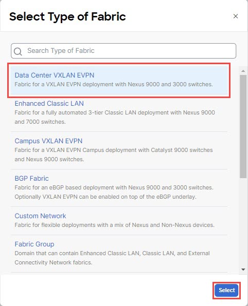
Choose the NDFC template, then click Add.

Step 5

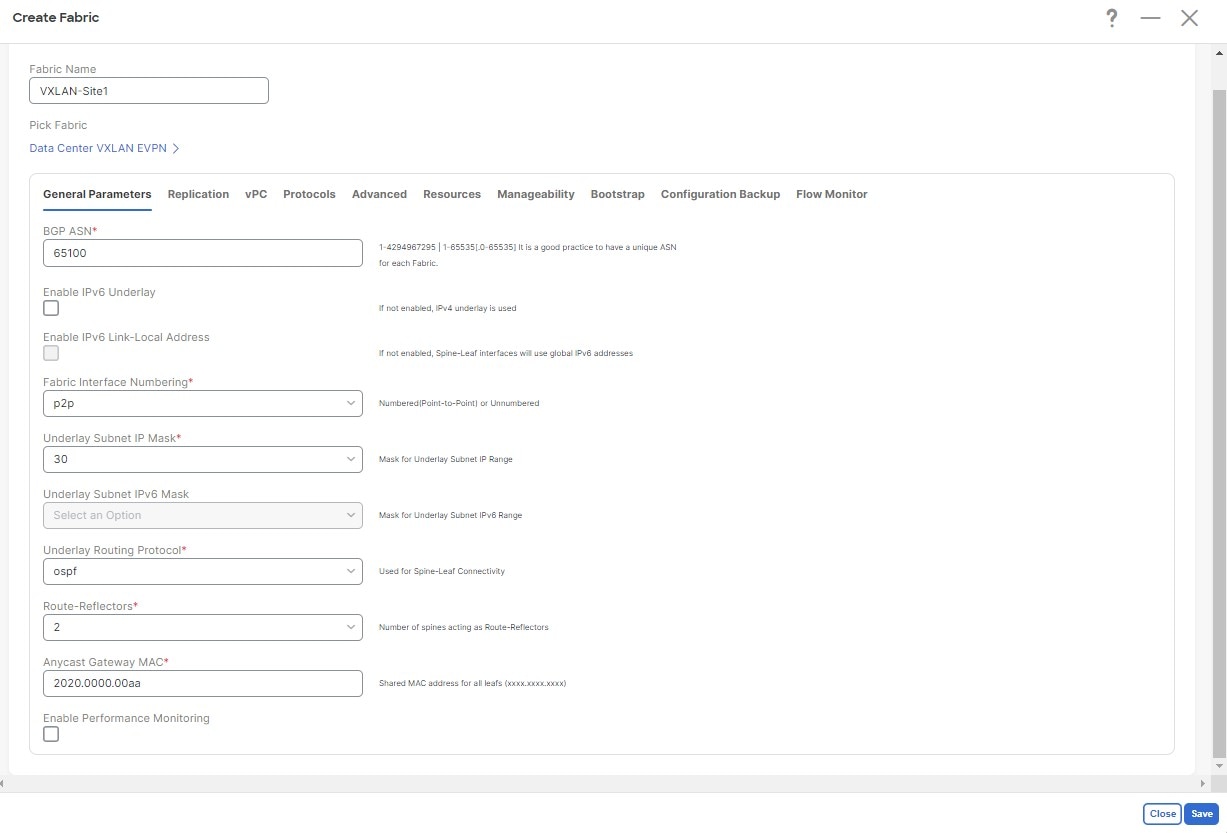
Enter a name in the Display Name field to create an NDFC-type template (for example, Template 1) and select the dcnm-default-tn tenant in the Select a Tenant field to map the template to that tenant.

Step 6

Under Template Properties, click Create Object and choose VRF to create a VRF.

Step 7

Enter a name in the Display Name field for the VRF (for example, VRF-1).

Step 8

Create a network under the VRF-1 VRF on Template 1.

  1. Under Template Properties, click Create Object and choose Network to create a network.

  2. Enter a name in the Display Name field for the network (for example, network-10).

  3. In the Virtual Routing & Forwarding field, choose the VRF-1 VRF to map network-10 to that VRF.

  4. In the Gateway IP field, click Add Subnet.

    The Add Subnet window appears.

  5. Click Add Gateway IP and provide the gateway IP address, then click the checkmark to accept the value and click Add.

    The gateway IP address is now displayed in the Gateway IP field.

  6. Define other optional parameters for this network, if necessary.

Step 9

In the Template Properties area, click Actions > Sites Association.

Step 10

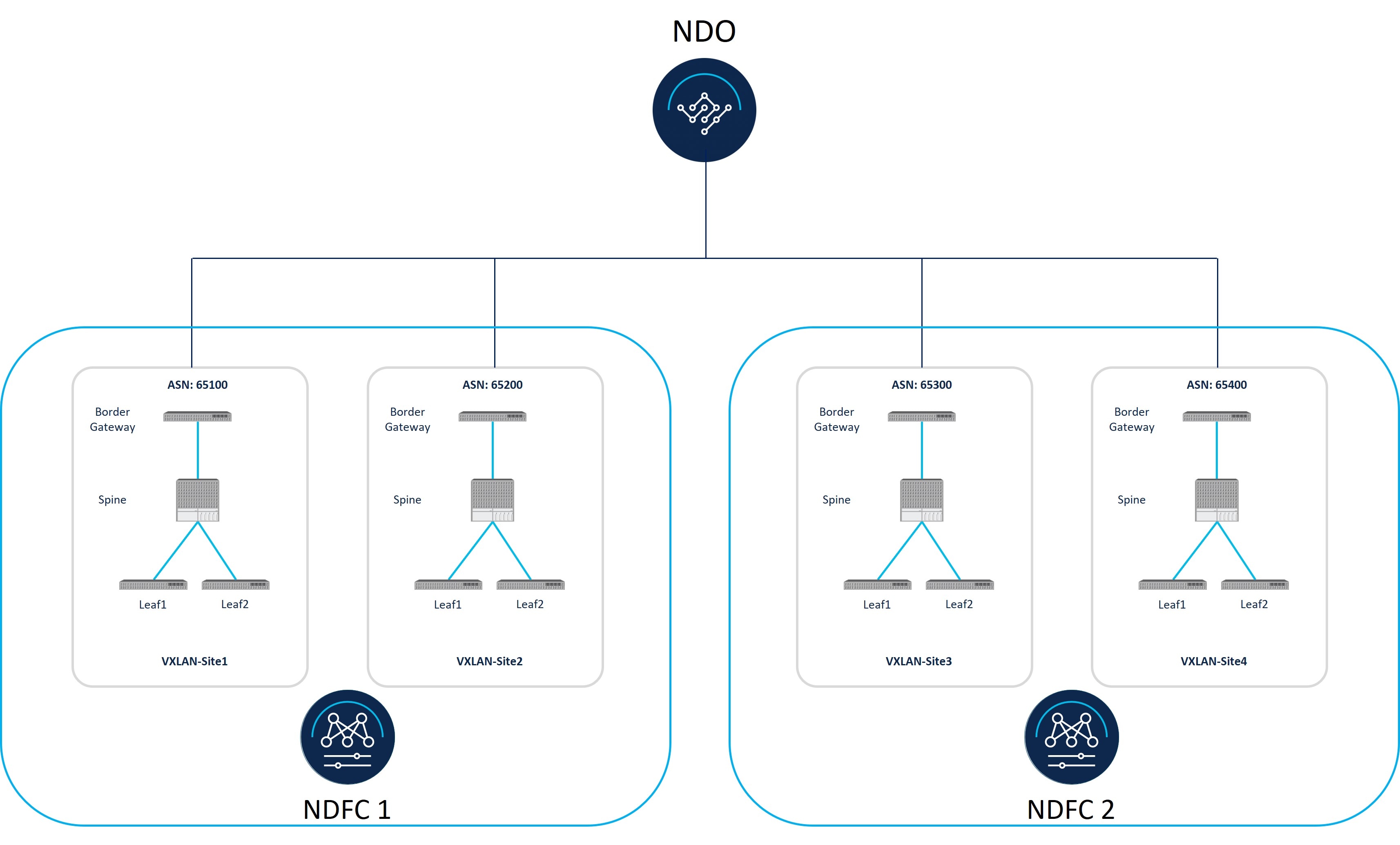
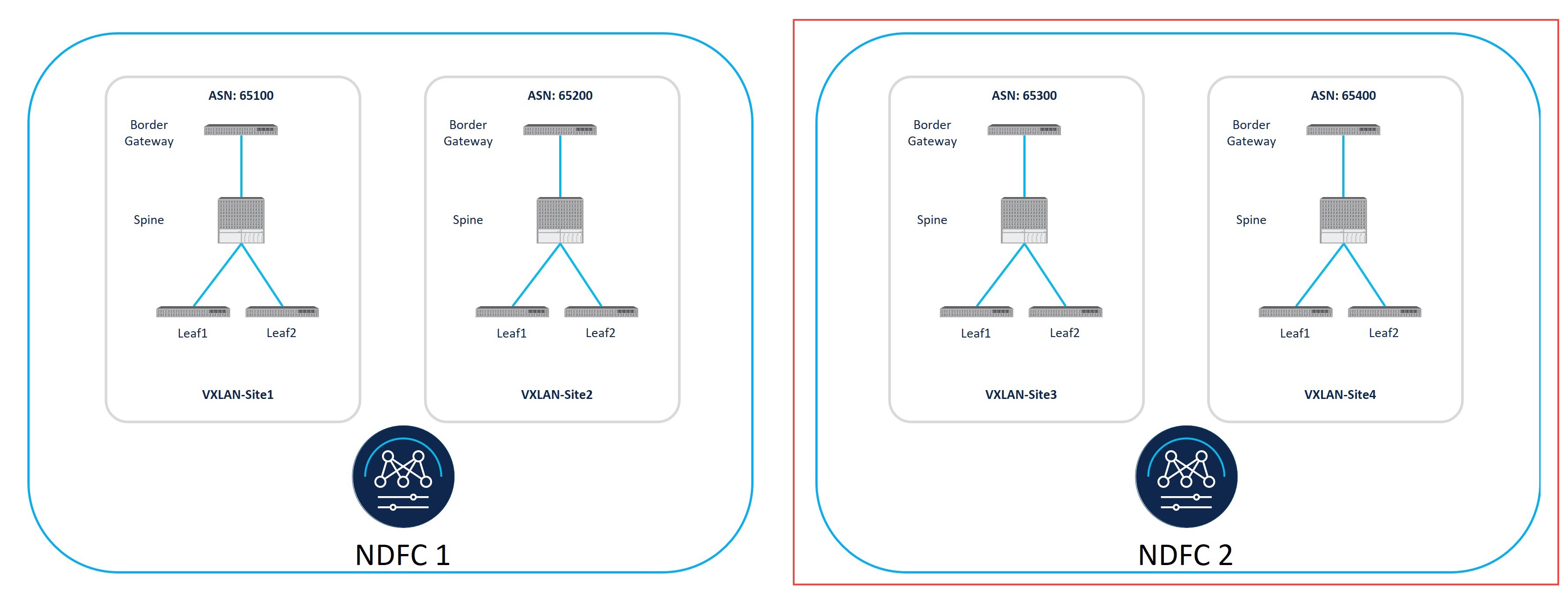
Associate this template to the four VLXLAN fabric sites, then click Ok.

You are returned to the Template 1 window.

Step 11

From the Template Properties drop-down, select the VXLAN-Site1 site.

Note


If you have already deployed the VRF and network in any of the VXLAN fabrics, these VRFs/networks can be imported to NDO in order to deploy and extend to other VXLAN fabrics. To import NDFC-created VRFs/networks in NDO, click Import under Template Properties.

Step 12

Click the VRF-1 VRF in the middle pane.

Step 13

In the right pane, click Add Static Leaf.

The Add Static Leaf window appears.

Step 14

In the Leaf field, select the BGW where this VRF is to be deployed (for example, the BGW in VXLAN-Site1) and click Ok.

You are returned to the Template 1 page.

Step 15

If you want to extend Layer 2/Layer 3 connectivity, where you are stretching this VRF from one fabric to another fabric, click Add Static Leaf again to add additional BGWs and leaf switches where this VRF is to be deployed.

For this use case, in the Leaf field, you would select the remaining BGWs where this VRF is to be deployed:

  • The BGW in VXLAN-Site2

  • The BGW in VXLAN-Site3

  • The BGW in VXLAN-Site4

When you have added all of the BGWs and leaf switches where this VRF is to be deployed, they will appear in the Template 1 page.

Step 16

Click the network-10 network, then click Add Static Port to add the ports where you want to deploy this network.

The Add Static Port window appears.

Step 17

In the Add Static Port window, click Add Path.

The Add Static Port window appears.

Step 18

In the Leaf field, select the device where you want to deploy this network.

Step 19

(Optional) Enter the necessary information in the VLAN field.

Step 20

In the Ports field, select the ports where you want to deploy this network.

Step 21

Click Save.

You are returned to the Add Static Port window.

Step 22

In the Add Static Port window, click Submit.

You are returned to the Template 1 window.

Step 23

From the Template Properties drop-down, select the VXLAN-Site2 site, then repeat Step 11 through Step 22 for the VXLAN-Site2 site.

  • Using the Add Static Leaf option, add the BGWs for each site, and any additional BGWs or leaf switches, where the VRF-1 VRF is to be deployed for the VXLAN-Site2 site.

  • Using the Add Static Port option, select the ports where you want to deploy the network-10 network for the VXLAN-Site2 site.

Step 24

From the Template Properties drop-down, select the VXLAN-Site3 site, then repeat Step 11 through Step 22 for the VXLAN-Site3 site.

  • Using the Add Static Leaf option, add the BGWs for each site, and any additional BGWs or leaf switches, where the VRF-1 VRF is to be deployed for the VXLAN-Site3 site.

  • Using the Add Static Port option, select the ports where you want to deploy the network-10 network for the VXLAN-Site3 site.

Step 25

From the Template Properties drop-down, select the VXLAN-Site4 site, then repeat Step 11 through Step 22 for the VXLAN-Site4 site.

  • Using the Add Static Leaf option, add the BGWs for each site, and any additional BGWs or leaf switches, where the VRF-1 VRF is to be deployed for the VXLAN-Site4 site.

  • Using the Add Static Port option, select the ports where you want to deploy the network-10 network for the VXLAN-Site4 site.

Step 26

When you have completed these configurations for the all of the necessary sites, click Save in the upper right corner of the screen to save the Demo Schema schema.

Step 27

Click the arrow next to the site and from the drop-down menu, select Template Properties.

Step 28

Click Deploy to Sites.

The Deploy to Sites window appears, showing the sites where the template will be deployed.

Step 29

Click Deployment Plan for additional verification.

Click the individual sites in the Deployment Plan window to to see the deployment plan for each specific site.

Step 30

Click Deploy to have NDO push the configurations to NDFC.

Step 31

Verify that the configurations were deployed successfully.

Note that for each of these verification steps, the exact command that would be used specifically for the configurations in this use case are shown. Replace the appropriate variables in each command based on your configuration.

  1. In NDO, verify that the configurations were deployed successfully.

    • Verify that the Template 1 was deployed successfully.

    • Verify that the dcn-default-tn tenant was deployed successfully.

  2. In NDFC, verify that the following were done successfully:

    • Verify that one vrf and one network has been created.

    • Verify that the VRF was deployed successfully.

    • Verify that the network was deployed successfully.