Cisco Nexus Dashboard Deployment and Upgrade Guide, Release 4.1.x
Bias-Free Language
The documentation set for this product strives to use bias-free language. For the purposes of this documentation set, bias-free is defined as language that does not imply discrimination based on age, disability, gender, racial identity, ethnic identity, sexual orientation, socioeconomic status, and intersectionality. Exceptions may be present in the documentation due to language that is hardcoded in the user interfaces of the product software, language used based on RFP documentation, or language that is used by a referenced third-party product. Learn more about how Cisco is using Inclusive Language.
Prerequisites and guidelines for deploying the Nexus Dashboard cluster in Linux KVM
Before you proceed with deploying the Nexus Dashboard cluster in a Linux KVM, the KVM must meet these prerequisites and you
must follow these guidelines:
The KVM form factor must support your scale requirements.
Scale support and co-hosting vary based on the cluster form factor. You can use the Nexus Dashboard Capacity Planning tool to verify that the virtual form factor satisfies your deployment requirements.
Cisco does not support the use of nested virtualization environments. Deploying Nexus Dashboard on a virtual machine that
is itself running on a virtualized hypervisor (for example, KVM on ESXi) is not a supported configuration and may result in
performance degradation or system instability.
KVM deployments are supported for NX-OS and ACI fabrics, as well as for SAN deployments.
You must deploy in Red Hat Enterprise Linux 8.8, 8.10, or 9.4.
In order for Nexus Dashboard to be up and running on OS reboot scenarios, you must add the UUIDs in the fstab conf files of your RHEL host operating system, which is the only way to preserve the Nexus Dashboard upon a reboot of the RHEL
operating system.
You must also configure the following required network bridges at the host level for Nexus Dashboard deployments:
Management Network Bridge (mgmt-bridge): The external network to manage Nexus Dashboard.
Data Network Bridge (data-bridge): The internal network used to form clustering within Nexus Dashboard.
We recommend that each Nexus Dashboard node is deployed in a different KVM hypervisor.
Verify the I/O latency of a Linux KVM storage device
When you deploy a Nexus Dashboard cluster in a Linux KVM, the storage device of the KVM must have a latency under 20ms.
Follow these steps to verify the I/O latency of a Linux KVM storage device.
After you use the command, confirm that the 99.00th=[value] in the fsync/fdatasync/sync_file_range section is under 20ms.
Understanding system resources
When deploying a Nexus Dashboard cluster in Linux KVM, the KVM must have enough system resources. There are multiple form
factors supported with a virtual Nexus Dashboard KVM, and the amount of system resources needed for each node differs based
on the form factor.
The following steps assume you copied the image into the /home/nd-base directory.
Step 3
Make the following configurations on each KVM host:
Edit /etc/libvirt/qemu.conf and make sure the user and group is correctly configured based on the ownership of the storage that you plan to use for the
Nexus Dashboard deployment.
This is only required if you plan to use disk storage paths that are different from the default libvirtd.
Edit /etc/libvirt/libvirt.conf and uncomment uri_default.
Restart the libvirtd service after updating the configuration using the systemctl restart libvirtd command from root.
Step 4
Log in to your KVM host as the root user and perform the following steps to create the required disk images on each node.
As mentioned in Understanding system resources, you will need a total of 550 GB or 3 TB of SSD storage to create two disk images:
Boot disk based on QCOW2 image that you downloaded
Data disk
Verify that you have a directory with enough space to store the VM disks (for example, /home/nd-node1) or mount the storage disk (raw disk or LVM) to directory /opt/cisco/nd.
Create the following script as /root/create_vm.sh under the root directory.
Note
If you manually type this information, verify that there are no empty spaces present after any of these lines.
Repeat previous steps to deploy the second and third nodes, then start all VMs.
Note
If you are deploying a single-node cluster, you can skip this step.
Step 7
Open one of the node's console and configure the node's basic information.
Press any key to begin initial setup.
You will be prompted to run the first-time setup utility:
[ OK ] Started atomix-boot-setup.
       Starting Initial cloud-init job (pre-networking)...
       Starting logrotate...
       Starting logwatch...
       Starting keyhole...
[ OK ] Started keyhole.
[ OK ] Started logrotate.
[ OK ] Started logwatch.

Press any key to run first-boot setup on this console...
Enter and confirm the admin password
This password will be used for the rescue-user SSH login as well as the initial GUI password.
Note
You must provide the same password for all nodes or the cluster creation will fail.
Admin Password:
Reenter Admin Password:
Enter the management network information.
Management Network:
  IP Address/Mask: 192.168.9.172/24
  Gateway: 192.168.9.1
For the first node only, designate it as the "Cluster Leader".
You will log into the cluster leader node to finish configuration and complete cluster creation.
Is this the cluster leader?: y
Review and confirm the entered information.
You will be asked if you want to change the entered information. If all the fields are correct, choose n to proceed. If you want to change any of the entered information, enter y to re-start the basic configuration script.
Please review the config
Management network:
  Gateway: 192.168.9.1
  IP Address/Mask: 192.168.9.172/24
Cluster leader: yes

Re-enter config? (y/N): n
Step 8
Repeat previous step to configure the initial information for the second and third nodes.
You do not need to wait for the first node configuration to complete, you can begin configuring the other two nodes simultaneously.
Note
You must provide the same password for all nodes or the cluster creation will fail.
The steps to deploy the second and third nodes are identical with the only exception being that you must indicate that they
are not the Cluster Leader.
Step 9
Wait for the initial bootstrap process to complete on all nodes.
After you provide and confirm management network information, the initial setup on the first node (Cluster Leader) configures the networking and brings up the UI, which you will use to add two other nodes and complete the cluster deployment.
Please wait for system to boot: [#########################] 100%
System up, please wait for UI to be online.

System UI online, please login to https://192.168.9.172 to continue.
Step 10
Open your browser and navigate to https://<node-mgmt-ip> to open the GUI.
The rest of the configuration workflow takes place from one of the node's GUI. You can choose any one of the nodes you deployed
to begin the bootstrap process and you do not need to log in to or configure the other two nodes directly.
Enter the password you entered in a previous step and click Login
Step 11
Enter the requested information in the Basic Information page of the Cluster Bringup wizard.
For Cluster Name, enter a name for this Nexus Dashboard cluster.
The cluster name must follow the RFC-1123 requirements.
For Select the Nexus Dashboard Implementation type, choose either LAN or SAN then click Next.
Step 12
Enter the requested information in the Configuration page of the Cluster Bringup wizard.
(Optional) If you want to enable IPv6 functionality for the cluster, put a check in the Enable IPv6 checkbox.
Click +Add DNS provider to add one or more DNS servers, enter the DNS provider IP address, then click the checkmark icon.
(Optional) Click +Add DNS search domain to add a search domain, enter the DNS search domain IP address, then click the checkmark icon.
(Optional) If you want to enable NTP server authentication, put a check in the NTP Authentication checkbox.
If you enabled NTP authentication, click + Add Key, enter the required information, and click the checkmark icon to save the information.
Key–Enter the NTP authentication key, which is a cryptographic key that is used to authenticate the NTP traffic between the Nexus
Dashboard and the NTP servers. You will define the NTP servers in the following step, and multiple NTP servers can use the
same NTP authentication key.
ID–Enter a key ID for the NTP host. Each NTP key must be assigned a unique key ID, which is used to identify the appropriate
key to use when verifying the NTP packet.
Authentication Type–Choose authentication type for the NTP key.
Put a check in the Trusted checkbox if you want this key to be trusted. Untrusted keys cannot be used for NTP authentication.
If you want to enter additional NTP keys, click + Add Key again and enter the information.
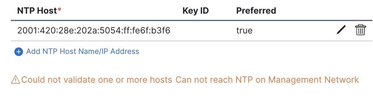
If you enabled NTP authentication, click +Add NTP Host Name/IP Address, enter the required information, and click the checkmark icon to save the information.
NTP Host–Enter an IP address; fully qualified domain names (FQDN) are not supported.
Key ID–Enter the key ID of the NTP key you defined in the previous substep.
If NTP authentication is disabled, this field is grayed out.
Put a check in the Preferred checkbox if you want this host to be preferred.
Note
If the node into which you are logged in is configured with only an IPv4 address, but you have checked Enable IPv6 in a previous step and entered an IPv6 address for an NTP server, you will get the following validation error:
This is because the node does not have an IPv6 address yet and is unable to connect to an IPv6 address of the NTP server.
You will enter IPv6 address in the next step. In this case, enter the other required information as described in the following
steps and click Next to proceed to the next page where you will enter IPv6 addresses for the nodes.
If you want to enter additional NTP servers, click +Add NTP Host Name/IP Address again and enter the information.
For Proxy Server, enter the URL or IP address of a proxy server.
For clusters that do not have direct connectivity to Cisco cloud, we recommend configuring a proxy server to establish the
connectivity. This allows you to mitigate risk from exposure to non-conformant hardware and software in your fabrics.
You can click +Add Ignore Host to enter one or more destination IP addresses for which traffic will skip using the proxy.
If you do not want to configure a proxy, click Skip Proxy then click Confirm.
(Optional) If your proxy server requires authentication, put a check in the Authentication required for Proxy checkbox and enter the login credentials.
(Optional) Expand the Advanced Settings category and change the settings if required.
Under advanced settings, you can configure these settings:
App Network–The address space used by the application's services running in the Nexus Dashboard. Enter the IP address and netmask.
Service Network–An internal network used by Nexus Dashboard and its processes. Enter the IP address and netmask.
App Network IPv6–If you put a check in the Enable IPv6 checkbox earlier, enter the IPv6 subnet for the app network.
Service Network IPv6–If you put a check in the Enable IPv6 checkbox earlier, enter the IPv6 subnet for the service network.
In the Node Details page, update the first node's information.
You have defined the Management network and IP address for the node into which you are currently logged in during the initial
node configuration in earlier steps, but you must also enter the Data network information for the node before you can proceed
with adding the other primary nodes and creating the cluster.
For Cluster Connectivity, if your cluster is deployed in L3 HA mode, choose BGP. Otherwise, choose L2.
You can enable BGP at this time or in the Nexus Dashboard GUI after the cluster is deployed. All remaining nodes need to configure
BGP if it is configured. You must enable BGP now if the data network of nodes have different subnets.
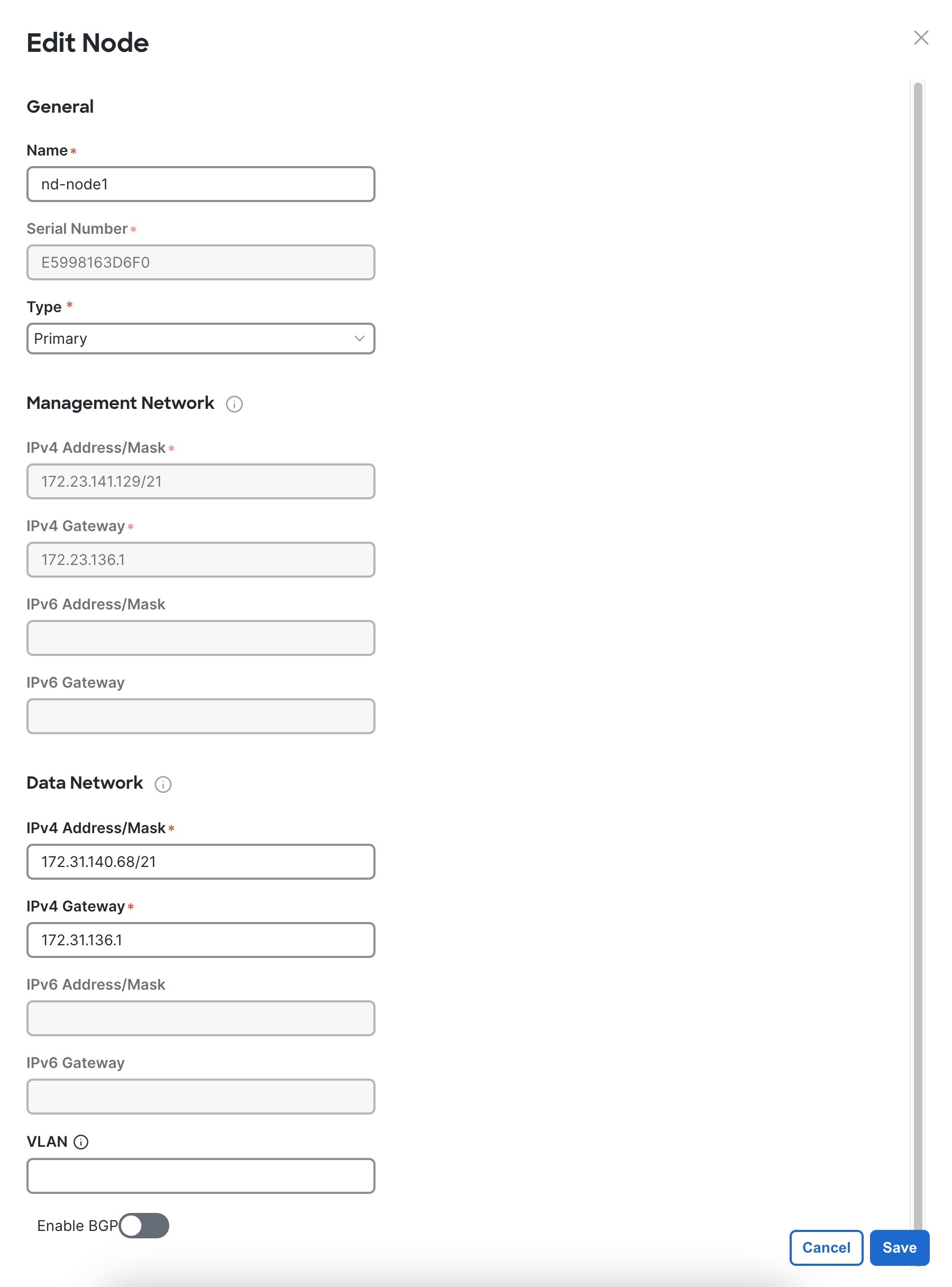
Click the Edit button next to the first node.
The node's Serial Number, Management Network information, and Type are automatically populated, but you must enter the other information.
For Name, enter a name for the node.
The node's Name will be set as its hostname, so it must follow the RFC-1123 requirements.
Note
If you need to change the name but the Name field is not editable, run the CIMC validation again to fix this issue.
For Type, choose Primary.
The first nodes of the cluster must be set to Primary. You will add the secondary nodes in a later step if required for higher scale.
In the Data Network area, enter the node's data network information.
Enter the data network IP address, netmask, and gateway. Optionally, you can also enter the VLAN ID for the network. Leave
the VLAN ID field blank if your configuration does not require VLAN. If you chose BGP for Cluster Connectivity, enter the ASN.
If you enabled IPv6 functionality in a previous page, you must also enter the IPv6 address, netmask, and gateway.
Note
If you want to enter IPv6 information, you must do so during the cluster bootstrap process. To change the IP address configuration
later, you would need to redeploy the cluster.
All nodes in the cluster must be configured with either only IPv4, only IPv6, or dual stack IPv4/IPv6.
If you chose BGP for Cluster Connectivity, then in the BGP peer details area, enter the peer's IPv4 address and ASN.
You can click + Add IPv4 BGP peer to add addition peers.
If you enabled IPv6 functionality in a previous page, you must also enter the peer's IPv6 address and ASN.
Click Save to save the changes.
Step 14
In the Node Details screen, click Add Node to add the second node to the cluster.
If you are deploying a single-node cluster, skip this step.
In the Deployment Details area, provide the Management IP Address and Password for the second node
You defined the management network information and the password during the initial node configuration steps.
Click Validate to verify connectivity to the node.
The node's Serial Number and the Management Network information are automatically populated after connectivity is validated.
Provide the Name for the node.
From the Type dropdown, select Primary.
The first 3 nodes of the cluster must be set to Primary. You will add the secondary nodes in a later step if required for higher scale.
In the Data Network area, provide the node's Data Network information.
You must provide the data network IP address, netmask, and gateway. Optionally, you can also provide the VLAN ID for the network.
For most deployments, you can leave the VLAN ID field blank.
If you had enabled IPv6 functionality in a previous screen, you must also provide the IPv6 address, netmask, and gateway.
Note
If you want to provide IPv6 information, you must do it during cluster bootstrap process. To change IP configuration later,
you would need to redeploy the cluster.
All nodes in the cluster must be configured with either only IPv4, only IPv6, or dual stack IPv4/IPv6.
(Optional) If your cluster is deployed in L3 HA mode, Enable BGP for the data network.
In the Summary screen, review and verify the configuration information and click Save to build the cluster.
During the node bootstrap and cluster bring-up, the overall progress as well as each node's individual progress will be displayed
in the UI. If you do not see the bootstrap progress advance, manually refresh the page in your browser to update the status.
It may take up to 30 minutes for the cluster to form and all the services to start. When cluster configuration is complete,
the page will reload to the Nexus Dashboard GUI.
Step 18
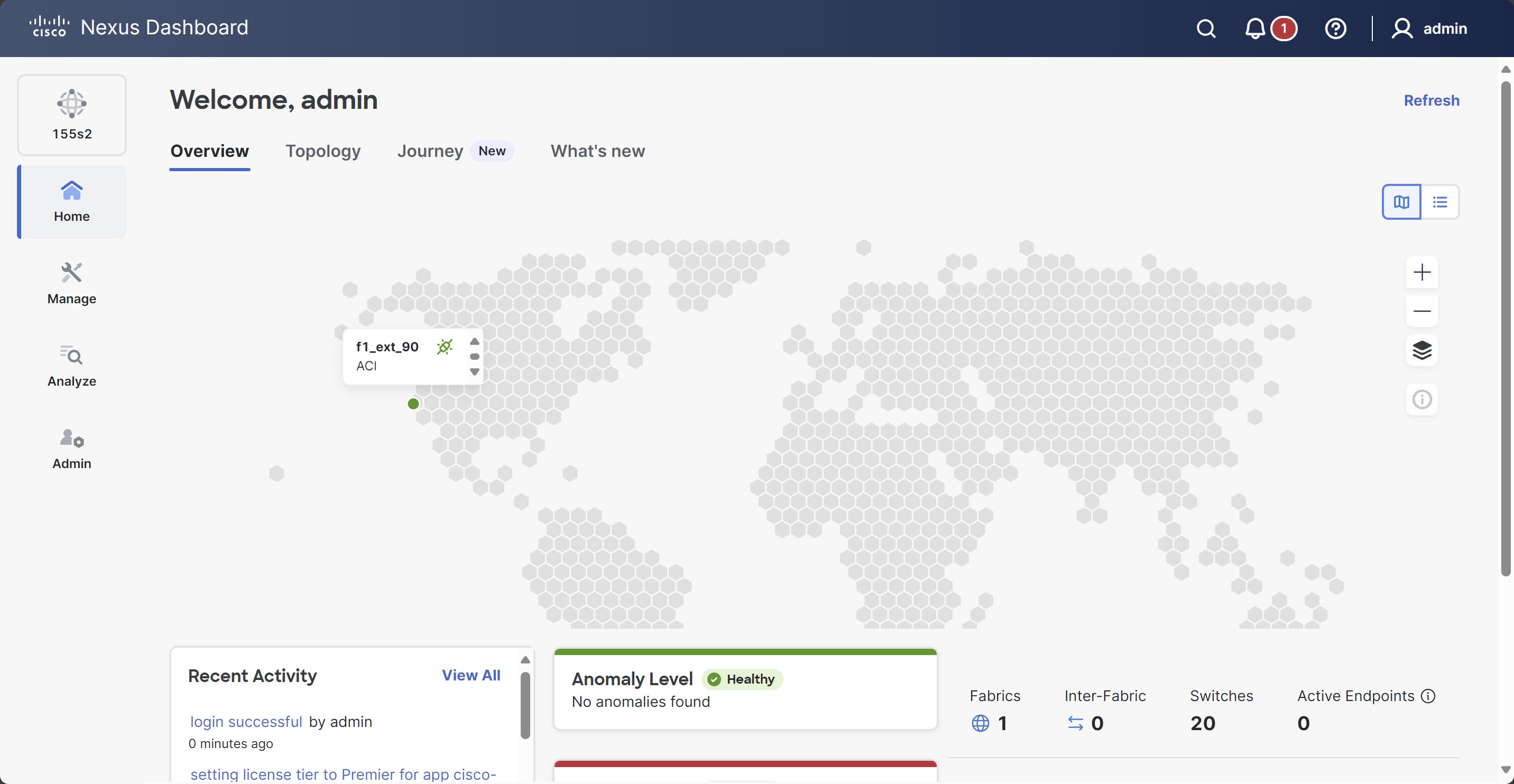
Verify that the cluster is healthy.
After the cluster becomes available, you can access it by browsing to any one of your nodes' management IP addresses. The
default password for the admin user is the same as the rescue-user password you chose for the first node. During this time, the UI will display a banner at the top stating "Service Installation
is in progress, Nexus Dashboard configuration tasks are currently disabled".
After all the cluster is deployed and all services are started, you can look at the Anomaly Level on the Home > Overview page to ensure the cluster is healthy:
Alternatively, you can log in to any one node using SSH as the rescue-user using the password you entered during node deployment and using the acs health command to see the status:
While the cluster is converging, you may see the following output:
$ acs healthk8s install is in-progress
$ acs healthk8s services not in desired state - [...]
$ acs healthk8s: Etcd cluster is not ready
When the cluster is up and running, the following output will be displayed:
$ acs health
All components are healthy
Note
In some situations, you might power cycle a node (power it off and then back on) and find it stuck in this stage:
deploy base system services
This is due to an issue with etcd on the node after a reboot of the physical Nexus Dashboard cluster.
To resolve the issue, enter the acs reboot clean command on the affected node.
Step 19
(Optional) Connect your Cisco Nexus Dashboard cluster to Cisco Intersight for added visibility and benefits. Refer to Working with Cisco Intersight for detailed steps.
Step 20
After you have deployed Nexus Dashboard, see the collections page for this release for configuration information.
What to do next
The next task is to create the fabrics and fabric groups. See the Creating Fabrics and Fabric Groups article for this release on the Cisco Nexus Dashboard collections page.
 Feedback