Cisco Nexus Dashboard Deployment and Upgrade Guide, Release 4.1.x
Bias-Free Language
The documentation set for this product strives to use bias-free language. For the purposes of this documentation set, bias-free is defined as language that does not imply discrimination based on age, disability, gender, racial identity, ethnic identity, sexual orientation, socioeconomic status, and intersectionality. Exceptions may be present in the documentation due to language that is hardcoded in the user interfaces of the product software, language used based on RFP documentation, or language that is used by a referenced third-party product. Learn more about how Cisco is using Inclusive Language.
Deploying a Virtual Nexus Dashboard (vND) in Amazon Web Services (AWS)
About hosting a vND on the AWS public cloud
This feature allows you to run a virtual Nexus Dashboard (vND) on the AWS public cloud. The components to this solution are:
Virtual Nexus Dashboard
Nexus 9000 switch
Two Catalyst 8000 series routers, or another type of device (such as the Nexus 9000 switch) that allows the Nexus Dashboard
to terminate the VXLAN tunnel from the vND to the on-premises data center for persistent IP address (PIP) traffic
AWS public cloud account
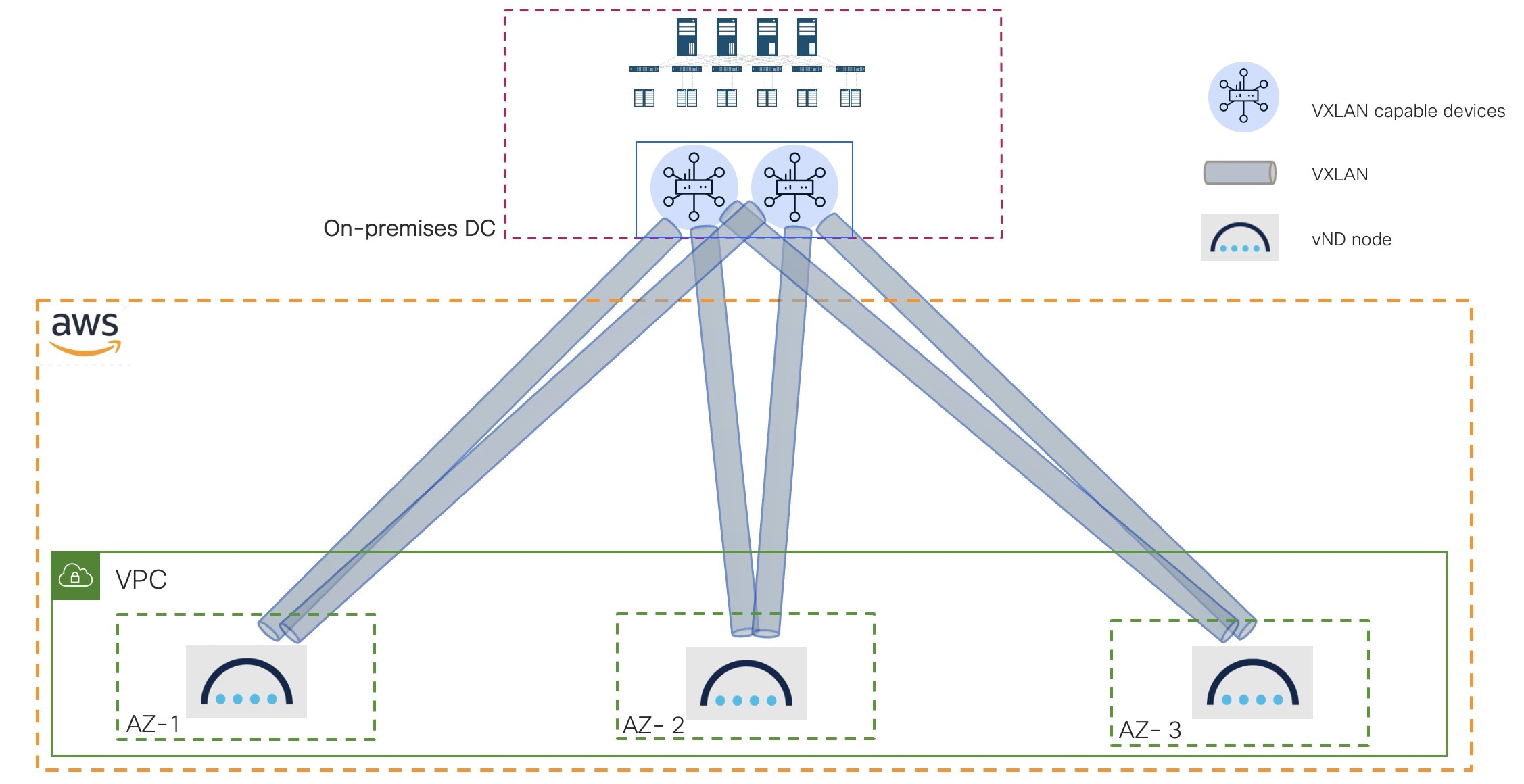
Understanding how vNDs are deployed on AWS public cloud
When you deploy the vNDs on the AWS public cloud, you do not have to do any manual bootstrapping; instead, the Nexus Dashboard
bootstrapping performs the bootstrapping automatically for you. Once you go through the vND deployment process on AWS public
cloud, a highly-available three-node cluster is created automatically for you across three availability zones (AZs) in a Virtual
Private Cloud (VPC). In the Nexus Dashboard GUI, navigate to Admin > System Status > Overview, then view the information on the three-node cluster in the Cluster nodes area.
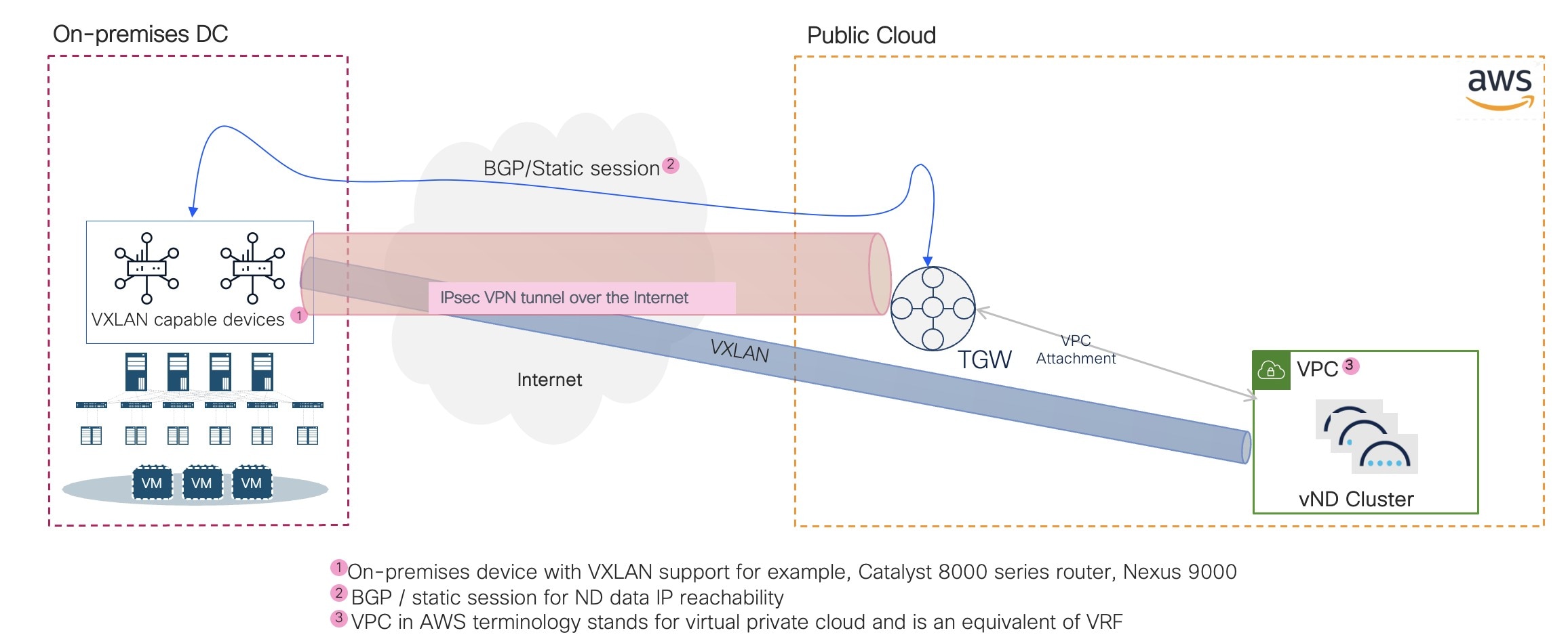
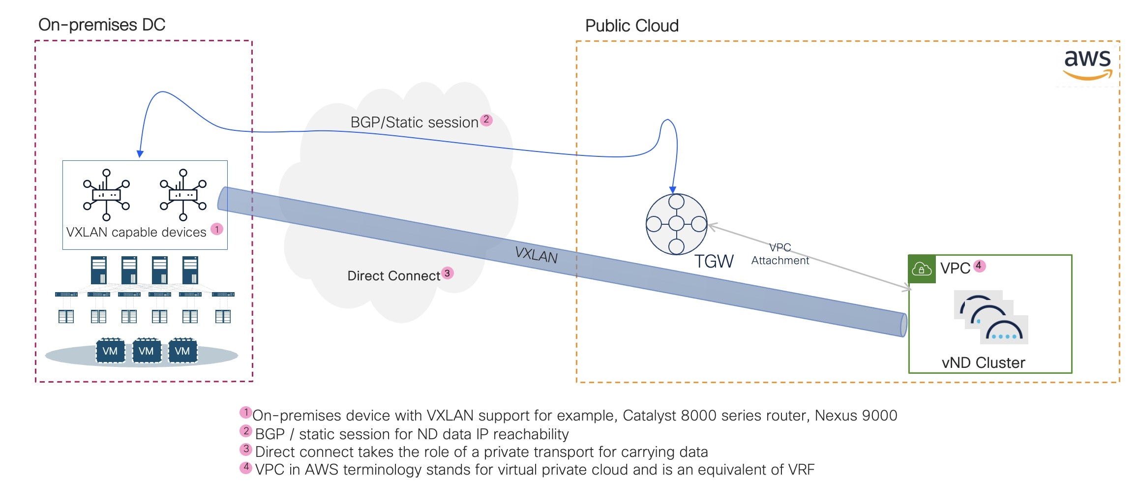
Example topology
These figures show example topologies:
Where:
The connectivity between your on-premises data center and the AWS public cloud is achieved using either direct connect (recommended
for production deployments) or an IPSec tunnel (for PoC or lab as additional overhead) between the two.
The two on-premises routers could be one of the following:
If you are using direct connect, you can use two physical switches, such as the Nexus 9000 switches.
If you are using an IPSec tunnel, you can use a network appliance from the Cisco 8000 family, with VXLAN support because you
will be terminating a VXLAN tunnel in this case.
A transit gateway is used to create transit gateway attachments to connect to the VPC (the app VPC) that hosts the Nexus Dashboard
nodes, as well as another transit gateway attachment, a VPN attachment or router, that is terminated on the transit gateway.
Note
The Catalyst 8000V (C8000V) was launched as an evolution of the Cisco Cloud Services Router (CSR) 1000V. Throughout this documentation,
C8000V will be used as an example of the VXLAN capable edge device. For more information, see Release Notes for Cisco Catalyst 8000V Edge Software.
Prerequisites and guidelines for deploying the vNDs in Amazon Web Services
Before you proceed with deploying the virtual Nexus Dashboards (vNDs) in Amazon Web Services (AWS):
Note
The vND type that is supported for AWS is vND data only with 32vCPU, 128G RAM, 3TB SSD (GP3) and 10G of network throughput.
This feature is supported on 3-node virtual clusters (data) on AWS with Nexus Dashboard as a single product (IPv4 only).
Only NX-OS fabrics are supported with this feature, and only with these enabled features:
Controller
Telemetry, with these restrictions:
Only out-of-band
Traffic analytics, but no flow telemetry
The Orchestration feature is not supported with this feature.
This feature is supported on LAN fabrics only. It is not supported on IP Fabric for Media (IPFM) or SAN fabrics.
Note
An AI fabric is considered a LAN fabric. Deploying this type of fabric in a vND in AWS is not restricted from a solution perspective.
The basic AI fabric requirement is to not exceed latency between devices and the vND over 50ms.
Secondary/worker nodes are not supported with this feature. Only three primary and one standby nodes are supported.
Scale per cluster: 100 switches on a single three-node vND cluster
You cannot change the IP address or the VNI assigned to the tunnel endpoints after you have deployed the vNDs in AWS.
Before you can deploy your Nexus Dashboard vNDs, it is best to have your on-premises site ready, with the Catalyst 8000 series
routers or a pair of Nexus 9000 switches already deployed, which allows you to provide the necessary BDI and TEP IP addresses
during the Nexus Dashboard vND deployment. If necessary, you can deploy the on-premises network appliances after you have
deployed your Nexus Dashboard vNDs, but then you will have to ensure that you configure the on-premises devices with the same
information that you provided during the Nexus Dashboard vND deployment. If you fail to provide the same configuration information
in both places, you might have to re-install the Nexus Dashboard vNDs again.
Verify that your on-premises VXLAN capable device is configured properly:
Dataplane: Ingress Replication
Control Plane: Flood and Learn
Ensure that the AWS form factor supports your scale and services requirements.
Scale and services support and co-hosting vary based on the cluster form factor. You can use the Nexus Dashboard Capacity Planning tool to verify that the cloud form factor satisfies your deployment requirements.
Prepare Amazon Web Services for the Nexus Dashboard cluster
Before you deploy the Nexus Dashboard vNDs in Amazon Web Services (AWS), follow these prerequisites to prepare AWS for your
deployment:
Familiarize yourself with AWS and how it works.
(Optional) Establish a connection between AWS and your on-premises data center (ideally, a direct connection).
Identify the region that you will use for the deployment of the Nexus Dashboard nodes.
Have an existing VPC, or create a new VPC, that you will use for this deployment.
Enable external access.
This is necessary for mapping Elastic IP addresses to the vND management interfaces and for accessing the GUI and SSH externally.
You may or may not need to create and attach an Internet Gateway to the VPC to enable external access, depending on the connection
method that you choose:
Option 1: Connecting the management interface using the Ethernet Interface Processor (EIP), in which case you will need the Internet
Gateway.
Option 2: Use a private IP address, in which case you will not need the Internet Gateway.
Update the security group to allow access from your public IP address or range for required services, such as:
HTTPS (TCP port 443): For accessing the Nexus Dashboard GUI
SSH (TCP port 22): For secure remote login to the vND nodes
This is necessary so that you can access the GUI and SSH into the Nexus Dashboard nodes.
Create 6 subnets:
One set of subnets for management for each node (3) - minimum /28
One set of subnets for data for each node (3) - minimum /28
Subnets for management and data for a specific node must be in the same availability zone.
Ensure that you have enough AWS Elastic IP addresses available for the vND deployment.
This installation requires 3 AWS Elastic IP addresses, 1 for each node, where each AWS Elastic IP address is used to access
the management services, such as accessing the vND UI or SSH.
Because the management subnets IP addresses will be mapped with AWS Elastic IP addresses as part of the deployment, those
management subnets will need external access. Data subnets need to have reachability to the on-premises devices and on-premises
Catalyst 8000 series routers (or other devices, such as Nexus 9000 switches) used for the termination of the VXLAN tunnel
(used by persistent pods) from the vNDs.
One /28 (such as 100.100.100.0/28) subnet that is not owned by AWS and comes from the on-premises data center (but is not
already being used) that will be used by the PIP (persistent IP addresses), where 100.100.100.1 and 100.100.100.2 of that
subnet must be the BDI IP addresses on the on-premises data center devices (Catalyst 8000 or Nexus 9000 switches) and the
rest of the IP addresses are used by vND persistent pods (trap, telemetry collectors, and so on).
On-premises devices should be able to reach these persistent IP addresses and Nexus Dashboard data IP addresses, and vice
versa, for proper functioning.
Create a security group with all the necessary IP addresses and ports so that the vND nodes can communicate with each other
and form the cluster, and communicate externally and with the on-premises devices.
Configure one EC2 key pair for deployment.
Note
Complete this configuration as part of the prerequisites, even though EC2 key pair is not currently used and user/password
is the only supported option at this time.
Deploy a virtual Nexus Dashboard (vND) in Amazon Web Services (AWS)
This section describes how to deploy a virtual Nexus Dashboard (vND) in Amazon Web Services (AWS).
Software version: Choose the latest 4.1.1 option available from the dropdown list.
Region: Choose the appropriate region where the template will be deployed.
This must be the same region where you created your VPC.
Click Continue to Launch.
In the Launch this software page for Cisco Nexus Dashboard - Cloud, locate the Choose Action field and choose Launch CloudFormation from the dropdown list, then click Launch.
The Create stack page appears.
Step 3
Complete the stack configuration.
Leave the options in the Create stack page as-is.
Note
Do not make changes in the provided template. Only by using the smart default template configuration can you ensure a successful
cluster formation.
Review the information provided in the Parameters area and make changes, if necessary.
For the most part, you can leave the pre-populated fields as-is based on the configurations that are part of this vND CFT.
In the Nexus Dashboard Cluster Name field, enter the cluster name for the Nexus Dashboard cluster.
In the Fabric Deployment Mode field, the default LAN option is the only supported option for the Nexus Dashboard 4.1.1 release.
In the VPC identifier field, enter the VPC identifier.
The application VPC is automatically entered in this field. If you want to change the VPC in this field, choose another VPC
under VPC dashboard > Virtual private cloud > Your VPCs.
In the Security Group Identifier field, enter the security group identifier.
This is a pre-created security group that must allow ingress access for ports 22 and 443.
In the Instance Type field, specify the EC2 instance type for the node instances.
In the AMI Identifier field, specify the AWS AMI for the Nexus Dashboard.
In the Password field, enter the admin password for the Nexus Dashboard node.
The admin password for the Nexus Dashboard node must contain at least 1 letter, number, and special character (@$!%*#?&) and
must be between 8 and 64 characters in length.
(Optional) In the Key Pair Name field, specify the name of an existing SSH key pair to enable SSH access to the Nexus Dashboard.
Enter the necessary information in the DNS Configuration area.
In the Primary DNS Server IP field, enter the primary DNS server IP address.
In the Secondary DNS Server IP field, enter the secondary DNS server IP address.
In the Search Domain Name field, enter the search domain name.
(Optional) Enter the necessary information in the Proxy Configuration area.
In the Proxy Type field, specify the proxy type (for example, HTTP or HTTPS).
In the Proxy URL field, specify the full proxy URL, including the protocol and port (for example, http://proxy.example.com:8080).
In the Proxy Username field, specify the proxy username, if authentication is required.
In the Proxy Password field, specify the proxy password, if authentication is required.
In the Proxy Ignore Hosts IP field, specify the proxy ignore hosts IP addresses.
Only one entry is allowed in this field (for example, 192.168.10.101).
Enter the necessary information in the NTP Configuration area.
In the NTP Server Host field, specify the NTP server host.
In the NTP Server Key Identifier field, specify the NTP server key identifier.
In the NTP Server Preferred field, choose true if the server is preferred.
In the NTP Key Identifier field, specify the identifier for the NTP key.
In the NTP Key field, specify the key for the NTP key.
In the NTP Key Authentication Type field, specify the authentication type for the NTP key (for example, MDS or SHA1).
In the NTP Key Trusted field, specify true or false for whether the NTP key is trusted.
Enter the necessary information in the Cisco VXLAN Capable Device area.
In the Device VXLAN Identifier (VNI) field, enter a VNI value to be used for the VXLAN tunnel between the Cisco VXLAN capable device (if you are using an IPSec
tunnel) or Nexus 9000 switches (if you are using direct connect) and the Nexus Dashboard nodes.
A single VNI value will be used for all the VXLAN tunnels between the Cisco VXLAN capable devices and the Nexus Dashboard
nodes (the vNDs), as shown in this figure.
In the Device 1 Bridge Domain IP and Device 2 Bridge Domain IP fields, enter the bridge domain IP addresses for both of the Cisco VXLAN capable devices.
The bridge domain IP addresses for the devices should come from the subnet that you provide in the Private IP Subnet for Nexus Dashboard Pods field. For example, if you enter 100.100.100.0/28 in the Private IP Subnet for Nexus Dashboard Pods field, you might enter 100.100.100.1 and 100.100.100.2 as the bridge domain IP addresses for the devices.
In the Device 1 Tunnel Endpoint IP and Device 2 Tunnel Endpoint IP fields, enter the tunnel endpoint IP addresses (the data IP addresses) for both of the Cisco VXLAN capable devices.
In the Private IP Subnet for Nexus Dashboard Pods field, enter the private IP subnet to be used by the Nexus Dashboard pods.
The IP subnet size must be a /28, such as 100.100.100.0/28.
Note
This procedures in this section do not deploy any Cisco VXLAN capable devices; they only ensure Nexus Dashboard has all the
variables required to build connections with the edge devices.
In the Nexus Dashboard Node 1 Configuration, Nexus Dashboard Node 2 Configuration, and Nexus Dashboard Node 3 Configuration areas, enter the necessary information for each of the vND nodes in the cluster:
ND Node x Hostname: Enter the hostname for each Nexus Dashboard node.
ND Node x Management Subnet: Enter the first management subnet each Nexus Dashboard node.
ND Node x Static Management IP: Enter a static management IP address from the management subnet that you entered above for each Nexus Dashboard node.
Verify that the IP address that you enter in this field is not being used already.
ND Node x Management Subnet Netmask: Enter the first management subnet netmask for each Nexus Dashboard node in the CIDR format (16-28).
ND Node x Management Subnet Gateway: Enter the first management default gateway on the management subnet that you entered above for each Nexus Dashboard node.
This is typically the first address on the subnet.
ND Node x Data Subnet: Enter the first data subnet each Nexus Dashboard node.
ND Node x Static Data IP: Enter a static data IP address from the management subnet that you entered above for each Nexus Dashboard node.
Verify that the IP address that you enter in this field is not being used already.
ND Node x Data Subnet Netmask: Enter the first data subnet netmask for each Nexus Dashboard node in the CIDR format (16-28).
ND Node x Data Subnet Gateway: Enter the first data default gateway on the management subnet that you entered above for each Nexus Dashboard node.
This is typically the first address on the subnet.
In the Kubernetes Network Configuration (Optional) area, enter the configuration information, if necessary:
In the Kubernetes Service Network field, specify the network address for the Kubernetes service network.
The CIDR range is fixed to /16.
In the Kubernetes App Network field, specify the network address for the Kubernetes app network.
The CIDR range is fixed to /16.
Click Next to continue.
Step 5
In the Configure stack options page, review and modify the information provided in this page, if necessary.
Under Stack failure options, we recommend that you change the choice under Behavior on provisioning failure to Preserve successfully provisioned resources.
Click Next when you have finished reviewing or modifying the information in the Configure stack options page.
Step 6
In the Review and create page, verify the template configuration information, then click Submit.
Step 7
Wait for the deployment to complete, then start the VMs.
You can view the status of the instance deployment in the CloudFormation > Stacks page, for example CREATE_IN_PROGRESS. You can click the refresh button in the top right corner of the page to update the status.
When the status for your stack changes to CREATE_COMPLETE, you can proceed to the next step.
Step 8
In your stack under CloudFormation > Stacks, click the Outputs tab to view the public IP addresses for the three vNDs in the cluster.
Note
The CloudFormation template takes care of the connectivity within the cluster. Nodes should automatically form a cluster,
if all the variables are filled in correctly.
Step 9
Log into the Nexus Dashboard GUI using one of the public IP addresses listed in the previous step.
Note
You might have to wait for around 40 minutes after you have started the VMs before you can log into the Nexus Dashboard GUI
using one of the public IP addresses.
Step 10
Verify that the cluster is healthy.
After the cluster becomes available, you can access it by browsing to any one of your nodes' management IP addresses. The
default password for the admin user is the same as the rescue-user password you chose for the first node. During this time, the UI will display a banner at the top stating "Service Installation
is in progress, Nexus Dashboard configuration tasks are currently disabled".
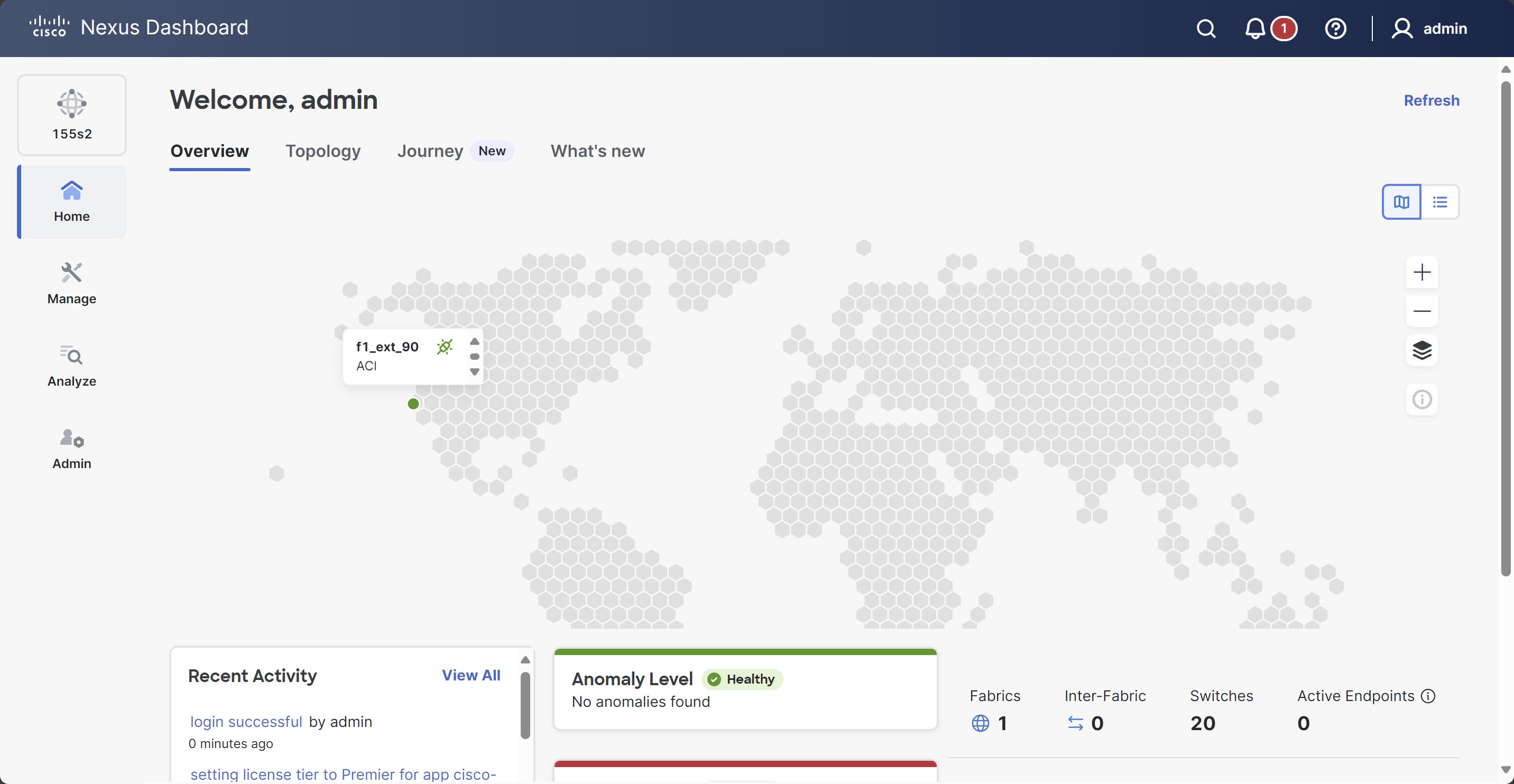
After all the cluster is deployed and all services are started, you can look at the Anomaly Level on the Home > Overview page to ensure the cluster is healthy:
Alternatively, you can log in to any one node using SSH as the rescue-user using the password you entered during node deployment and using the acs health command to see the status:
While the cluster is converging, you may see the following output:
$ acs healthk8s install is in-progress
$ acs healthk8s services not in desired state - [...]
$ acs healthk8s: Etcd cluster is not ready
When the cluster is up and running, the following output will be displayed:
$ acs health
All components are healthy
Note
In some situations, you might power cycle a node (power it off and then back on) and find it stuck in this stage:
deploy base system services
This is due to an issue with etcd on the node after a reboot of the physical Nexus Dashboard cluster.
To resolve the issue, enter the acs reboot clean command on the affected node.
Step 11
(Optional) Connect your Cisco Nexus Dashboard cluster to Cisco Intersight for added visibility and benefits. Refer to Working with Cisco Intersight for detailed steps.
Step 12
After you have deployed Nexus Dashboard, see the collections page for this release for configuration information.
What to do next
The next task is to create the fabrics and fabric groups. See the Creating Fabrics and Fabric Groups article for this release on the Cisco Nexus Dashboard collections page.

 Feedback