
New and changed information
The following table provides an overview of the significant changes up to this current release. The table does not provide an exhaustive list of all changes or of the new features up to this release.
| Release Version | Feature | Description |
|---|---|---|
|
Nexus Dashboard 4.1.1 |
Improved navigation and workflow when preparing ACI fabrics and configuring fabric access policies for all APIC fabrics |
Beginning with Nexus Dashboard 4.1.1, Nexus Dashboard the navigation and workflow when preparing ACI fabrics and configuring fabric access policies for all APIC fabrics have been enhanced. |
|
Nexus Dashboard 4.1.1 |
ACI orchestration for autonomous remote leaf group |
Nexus Dashboard offers enhanced support for remote leaf deployments. It provides new vPC validations to ensure remote leaf switches in a vPC configuration belong to the same TEP pool. For improved management and visibility of remote leaf resiliency, the Nexus Dashboard inventory also displays Autonomous Remote Leaf Group (ARL Group) and TEP pool information. For more information, see Autonomous remote leaf group management. |
Pod Profile and Policy Group
In each fabric’s APIC, you must have one Pod profile with a Pod policy group. If your fabric does not have a Pod policy group you must create one. Typically, these settings will already exist as you will have configured them when you first deployed the fabric.
-
Log in to the fabric’s APIC GUI.
-
Check that the Pod profile contains a Pod policy group.
Navigate to Fabric > Fabric Policies > Pods > Profiles > Pod Profile default.
-
If necessary, create a Pod policy group.
-
Navigate to Fabric > Fabric Policies > Pods > Policy Groups.
-
Right-click Policy Groups and select Create Pod Policy Group.
-
Enter the appropriate information and click Submit.
-
-
Assign the new Pod policy group to the default Pod profile.
-
Navigate to Fabric > Fabric Policies > Pods > Profiles > Pod Profile default
-
Select the default profile.
-
Choose the new pod policy group and click Update.
-
Configuring Fabric Access Policies for All APIC Fabrics
Before your APIC fabrics can be added to and managed by the Nexus Dashboard, there is a number of fabric-specific access policies that you must configure on each fabric.
Configuring Fabric Access Global Policies
This section describes the global fabric access policy configurations that must be created for each APIC fabric before it can be added to and managed by the Nexus Dashboard.
-
Log in directly to the fabric’s APIC GUI.
-
From the main navigation menu, select Fabric > Access Policies.
You must configure a number of fabric policies before the fabric can be added to the Nexus Dashboard. From the APIC’s perspective, this is something you do just like you would if you were connecting a bare-metal host, where you would configure domains, AEPs, policy groups, and interface selectors; you must configure the same options for connecting the spine switch interfaces to the inter-fabric network for all the fabrics that will be part of the same Multi-Fabric domain.
-
Specify the VLAN pool.
The first thing you configure is the VLAN pool. We use Layer 3 sub-interfaces tagging traffic with VLAN-4 to connect the spine switches to the inter-fabric network.
-
In the left navigation tree, browse to Pools > VLAN.
-
Right-click the VLAN category and choose Create VLAN Pool.
In the Create VLAN Pool window, specify the following:
-
For the Name field, specify the name for the VLAN pool, for example
mfabric. -
For Allocation Mode, specify
Static Allocation. -
And for the Encap Blocks, specify just the single VLAN 4. You can specify a single VLAN by entering the same number in both Range fields.
-
-
-
Configure Attachable Access Entity Profiles (AEP).
-
In the left navigation tree, browse to Global Policies > Attachable Access Entity Profiles.
-
Right-click the Attachable Access Entity Profiles category and choose Create Attachable Access Entity Profiles.
In the Create Attachable Access Entity Profiles window, specify the name for the AEP, for example
mfabric-aep. -
Click Next and Submit
No additional changes, such as interfaces, are required.
-
-
Configure domain.
The domain you configure is what you will select from the Nexus Dashboard when adding this fabric.
-
In the left navigation tree, browse to Physical and External Domains > External Routed Domains.
-
Right-click the External Routed Domains category and choose Create Layer 3 Domain.
In the Create Layer 3 Domain window, specify the following:
-
For the Name field, specify the name the domain, for example
mfabric-l3. -
For Associated Attachable Entity Profile, select the AEP you created in Step 4.
-
For the VLAN Pool, select the VLAN pool you created in Step 3.
-
-
Click Submit.
No additional changes, such as security domains, are required.
-
After you have configured the global access policies, you must still add interfaces policies as described in Configuring Fabric Access Interface Policies.
Configuring Fabric Access Interface Policies
You must have configured the global fabric access policies, such as VLAN Pool, AEP, and domain, in the fabric’s APIC, as described in Configuring Fabric Access Global Policies.

Interface configuration for Cisco Application Centric Infrastructure (ACI) (Fabric > Access Policies > Interface Configuration) introduced in ACI 6.0.1 and 5.2.7 is not supported by Nexus Dashboard Orchestrator (NDO).
This section describes the fabric access interface configurations that must be done for the Nexus Dashboard on each APIC fabric.
-
Log in directly to the fabric’s APIC GUI.
-
From the main navigation menu, select Fabric > Access Policies.
In addition to the VLAN, AEP, and domain you have configured in previous section, you must also create the interface policies for the fabric’s spine switch interfaces that connect to the Inter-Fabric Network.
-
Configure a spine policy group.
-
In the left navigation tree, browse to Interface Policies > Policy Groups > Spine Policy Groups.
This is similar to how you would add a bare-metal server, except instead of a Leaf Policy Group, you are creating a Spine Policy Group.
-
Right-click the Spine Policy Groups category and choose Create Spine Access Port Policy Group.
In the Create Spine Access Port Policy Group window, specify the following:
-
For the Name field, specify the name for the policy group, for example
Spine1-PolGrp. -
For the Link Level Policy field, specify the link policy used between your spine switch and the ISN.
-
For CDP Policy, choose whether you want to enable CDP.
-
For the Attached Entity Profile, select the AEP you have configured in previous section, for example
mfabric-aep.
-
-
Click Submit.
No additional changes, such as security domains, are required.
-
-
Configure a spine profile.
-
In the left navigation tree, browse to Interface Policies > Profiles > Spine Profiles.
-
Right-click the Spine Profiles category and choose Create Spine Interface Profile.
In the Create Spine Interface Profile window, specify the following:
-
For the Name field, specify the name for the profile, for example
Spine1-ISN. -
For Interface Selectors, click the + sign to add the port on the spine switch that connects to the ISN. Then in the Create Spine Access Port Selector window, provide the following:
-
For the Name field, specify the name for the port selector, for example
Spine1-ISN. -
For the Interface IDs, specify the switch port that connects to the ISN, for example
5/32. -
For the Interface Policy Group, choose the policy group you created in the previous step, for example
Spine1-PolGrp.
Then click OK to save the port selector.
-
-
-
Click Submit to save the spine interface profile.
-
-
Configure a spine switch selector policy.
-
In the left navigation tree, browse to Switch Policies > Profiles > Spine Profiles.
-
Right-click the Spine Profiles category and choose Create Spine Profile.
In the Create Spine Profile window, specify the following:
-
For the Name field, specify the name for the profile, for example
Spine1. -
For Spine Selectors, click the + to add the spine and provide the following:
-
For the Name field, specify the name for the selector, for example
Spine1. -
For the Blocks field, specify the spine node, for example
201.
-
-
-
Click Update to save the selector.
-
Click Next to proceed to the next screen.
-
Select the interface profile you have created in the previous step
For example
Spine1-ISN. -
Click Finish to save the spine profile.
-
Configuring fabrics that contain remote leaf switches
Nexus Dashboard architecture supports ACI fabrics with Remote Leaf switches. The following sections describe guidelines, limitations, and configuration steps required to allow Nexus Dashboard to manage these fabrics.
Remote leaf
Remote leaf switches are leaf nodes that connect to the ACI Main Datacenter (DC) through a generic Inter-Pod Network (IPN). The remote leaf feature enables the extension of connectivity and the implementation of consistent policies to remote locations where deploying a complete ACI Pod (including leaf and spine nodes) may not be feasible or desirable. A remote location might consist of a small data center that does not require an extensive number of leaf switches for connectivity. These remote leaf switches establish connections back to spine nodes in the main ACI data center. These remote leaf switches are fully integrated into an existing pod within the fabric, operating like any standard leaf switch in that pod.
Nexus Dashboard 4.1.1 adds validation to ensure proper vPC configuration on remote leaf switches. The system validates that both nodes belong to the same remote leaf TEP pool when you configure vPC interfaces in a fabric resource template. A validation error occurs if the selected remote leaf switches belong to different TEP pools.
Cisco Nexus Dashboard facilitates centralized policy definition (intent) and management, providing the following functionalities:
-
Monitoring the health-state of the different ACI fabrics.
-
Provisioning of day-0 configuration to establish inter-fabric EVPN control plane.
-
Defining and provisioning policies across fabrics (scope of changes).
-
Inter-fabric troubleshooting.
-
Disaster Recovery
-
Multi-cloud connectivity
On remote leaf switches with ACI Release 6.1(1) and later, Nexus Dashboard can distinguish between local and remote leaf types, enabling the management of functions unique to remote leaf switches. Recent ACI releases have introduced new functionalities that specifically cater to remote leaf switches.
This enhancement allows for the utilization of a single uplink for both the fabric control and data plane connectivity on sub-interface VLAN 4, while also permitting the configuration of additional sub-interfaces for tenant L3Out (VRF-Lite) and SR-MPLS infrastructure L3Outs.
It is important to note that the tenant and SR-MPLS L3Outs cannot utilize sub-interface VLAN 4, as this is reserved for the remote leaf fabric interface. For more details on tenant L3Out from a remote leaf, please refer to the Cisco ACI Remote Leaf Architecture White Paper.
Autonomous remote leaf group management
Beginning with ACI Release 6.1(3), the remote leaf resiliency feature enables you to configure remote leaf switches in an Autonomous Remote Leaf Group (ARL Group). The Nexus Dashboard inventory view for remote leaf switches displays the remote leaf TEP pool and ARL Group information if an ARL Group is configured.
The inventory display of remote leaf TEP pool and remote leaf group information is not supported on Nexus Dashboard deployments with telemetry enabled.
Remote Leaf Switch Guidelines and Limitations
If you want to add an APIC fabric with a remote leaf switch to be managed by the Nexus Dashboard, the following guidelines and restrictions apply:
-
You must upgrade your Cisco APIC to Release 4.2(4) or later.
-
You can now use the same fabric port, used earlier for VXLAN connectivity with ACI fabric to provide connectivity toward the external network domain using local L3Out(s). For more information on tenant policy templates and L3Out configuration, see the "Creating L3Out Template" section in External Connectivity (L3Out) for ACI Fabrics.
-
Only -EX and -FX or later switches are supported as Remote Leaf switches for use with Multi-Fabric
-
Remote leaf is not supported with back-to-back connected fabrics without IPN switches.
-
Remote leaf switches in one fabric cannot use another fabric’s L3Out.
-
When a bridge domain is deployed to a remote leaf switch it must be local only to the fabric where the remote leaf belongs. Stretching a bridge domain deployed on a remote leaf switch to another fabric is not supported.
You must also perform the following tasks before the fabric can be added to and managed by the Nexus Dashboard:
-
You must add the routable IP addresses of Cisco APIC nodes in the DHCP-Relay configuration applied on the interfaces of the Layer 3 routers connecting to the Remote Leaf switches.
-
You must enable Remote Leaf direct communication and configure routable subnets directly in the fabric’s APIC, as described in the following sections.
The routable IP address of each APIC node is listed in the Routable IP field of the System > Controllers > <controller-name> screen of the APIC GUI.
Configuring Routable Subnets for Remote Leaf Switches
-
Upgrade Cisco APIC and all the nodes in the fabric to Release 4.1(2) or later.
-
Verify that the routes for the Routable Subnet that you wish to configure will be reachable in the Inter-Pod Network (IPN), and that the subnet is reachable from the remote leaf switches.
Before you can add a fabric that contains one or more Remote Leaf switches to the Nexus Dashboard, you must configure routable subnets for the pod with which the Remote Leaf nodes are associated.
-
Log in directly to the fabric’s APIC GUI.
-
From the menu bar, select Fabric > Inventory.
-
In the Navigation pane, click Pod Fabric Setup Policy.
-
On the Fabric Setup Policy panel, double-click the pod where you want to configure routable subnets.
-
Access the information in the subnets or TEP table, depending on the release of your APIC software:
-
For releases prior to 4.2(3), click the
+on the Routable Subnets table. -
For 4.2(3) only, click the
+on the External Subnets table. -
For 4.2(4) and later, click the
+on the External TEP table.
-
-
Enter the IP address and Reserve Address, if necessary, and set the state to active or inactive.
-
The IP address is the subnet prefix that you wish to configure as the routeable IP space.
-
The Reserve Address is a count of addresses within the subnet that must not be allocated dynamically to the spine switches and remote leaf switches. The count always begins with the first IP in the subnet and increments sequentially. If you wish to allocate the Unicast TEP (covered later in these procedures) from this pool, then it must be reserved.
-
-
Click Update to add the external routable subnet to the subnets or TEP table.
-
On the Fabric Setup Policy panel, click Submit.
If you find that you have to make changes to the information in the subnets or TEP table after you’ve made these configurations, follow the procedures provided in "Changing the External Routable Subnet" in the Cisco APIC Getting Started Guide to make those changes successfully.
Enabling Direct Communication for Remote Leaf Switches
Before you can add a fabric that contains one or more Remote Leaf switches to the Nexus Dashboard, you must configure direct remote leaf communication for that fabric. Additional information about remote leaf direct communication feature is available in the Cisco APIC Layer 3 Networking Configuration Guide. This section outlines the steps and guidelines specific to the integration with Multi-Fabric.
Once you enable Remote Leaf switch direct communication, the switches will function in the new mode only
-
Log in directly to the fabric’s APIC.
-
Enable direct traffic forwarding for Remote Leaf switches.
-
From the menu bar, navigate to System > System Settings.
-
From the left side bar, select Fabric Wide Setting.
-
Check the Enable Remote Leaf Direct Traffic Forwarding checkbox.
When this is enabled, the spine switches will install Access Control Lists (ACLs) to prevent traffic coming from remote leaf switches from being sent back, since the remote leaf switches will now send directly between each remote leaf switches' TEPs. There may be a brief disruption in service while the tunnels are built between the remote leaf switches.
-
Click Submit to save the changes.
-
-
To verify that the configuration was set correctly, on the spine switch, enter the following command:
spine# cat /mit/sys/summary
You should see the following highlighted line in the output, which is verification that the configuration was set correctly (full output truncated):podId : 1 remoteNetworkId : 0 remoteNode : no rldirectMode : yes rn : sys role : spine
Cisco Mini ACI Fabrics
Cisco Multi-Fabric supports Cisco Mini ACI fabrics as typical on-premises fabrics without requiring any additional configuration. This section provides a brief overview of Mini ACI fabrics, detailed info on deploying and configuring this type of fabrics is available in Cisco Mini ACI Fabric and Virtual APICs.
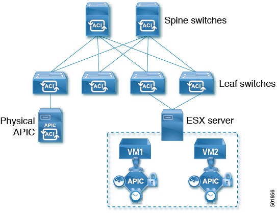
Cisco ACI release 4.0(1) introduced Mini ACI Fabric for small scale deployment. Mini ACI fabric works with APIC cluster consisting of one physical APIC and two virtual APICs (vAPIC) running in virtual machines. This reduces the physical footprint and cost of the APIC cluster, allowing ACI fabric to be deployed in scenarios with limited rack space or initial budget, such as a colocation facility or a single-room data center, where a full-scale ACI installations may not be practical due to physical footprint or initial cost.
The following diagram shows an example of a mini ACI fabric with a physical APIC and two virtual APICs (vAPICs):
Adding and Deleting Fabrics
Cisco Nexus Dashboard and APIC Interoperability Support
Cisco Nexus Dashboard does not require a specific version of APIC to be running in all fabrics. The APIC clusters in each fabric as well as the Nexus Dashboard itself can be upgraded independently of each other and run in mixed operation mode as long as the fabric can be on-boarded to the Nexus Dashboard. As such, we recommend that you always upgrade to the latest release of the Nexus Dashboard.
However, keep in mind that if you upgrade the Nexus Dashboard before upgrading the APIC clusters in one or more fabrics, some of the new Nexus Dashboard features may not yet be supported by an earlier APIC release. In that case a check is performed on each template to ensure that every configured option is supported by the target fabrics.
The check is performed when you save a template or deploy a template. If the template is already assigned to a fabric, any unsupported configuration options will not be saved; if the template is not yet assigned, you will be able to assign it to a fabric, but not be able to save or deploy the schema if it contains configuration unsupported by that fabric.
In case an unsupported configuration is detected, an error message will show, for example: This APIC fabric version <fabric-version> is not supported by Nexus Dashboard. The minimum version required for this <feature> is <required-version> or above.
The following table lists the features and the minimum required APIC release for each one:
While some of the following features are supported on earlier Cisco APIC releases, Release 4.2(4) is the earliest release that can be on-boarded and managed by this release of Nexus Dashboard.
|
Feature |
Minimum APIC Version |
|
ACI Multi-Pod Support |
Release 4.2(4) |
|
Service Graphs (L4-L7 Services) |
Release 4.2(4) |
|
External EPGs |
Release 4.2(4) |
|
ACI Virtual Edge VMM Support |
Release 4.2(4) |
|
DHCP Support |
Release 4.2(4) |
|
Consistency Checker |
Release 4.2(4) |
|
vzAny |
Release 4.2(4) |
|
Host Based Routing |
Release 4.2(4) |
|
Layer 3 Multicast |
Release 4.2(4) |
|
MD5 Authentication for OSPF |
Release 4.2(4) |
|
EPG Preferred Group |
Release 4.2(4) |
|
Inter-Fabric L3Out |
Release 4.2(4) |
|
EPG QoS Priority |
Release 4.2(4) |
|
Contract QoS Priority |
Release 4.2(4) |
|
Single Sign-On (SSO) |
Release 5.0(1) |
|
Multicast Rendezvous Point (RP) Support |
Release 5.0(1) |
|
Transit Gateway (TGW) support for AWS and Azure Fabrics |
Release 5.0(1) |
|
SR-MPLS Support |
Release 5.0(1) |
|
Cloud LoadBalancer High Availability Port |
Release 5.0(1) |
|
Service Graphs (L4-L7 Services) with UDR |
Release 5.0(2) |
|
3rd Party Device Support in Cloud |
Release 5.0(2) |
|
Cloud Loadbalancer Target Attach Mode Feature |
Release 5.1(1) |
|
Support security and service insertion in Azure for non-ACI networks reachable through Express Route |
Release 5.1(1) |
|
CSR Private IP Support |
Release 5.1(1) |
|
Extend ACI policy model and automation for Cloud native services in Azure |
Release 5.1(1) |
|
Flexible segmentation through multiple VRF support within a single VNET for Azure |
Release 5.1(1) |
|
Private Link automation for Azure PaaS and third-party services |
Release 5.1(1) |
|
Openshift 4.3 IPI on Azure with ACI-CNI |
Release 5.1(1) |
|
Cloud Fabric Underlay Configuration |
Release 5.2(1) |
Adding Cisco ACI Fabrics
-
If you are adding on-premises ACI fabric, you must have completed the fabric-specific configurations in each fabric’s APIC, as described in previous sections in this chapter.
-
You must ensure that one or more fabrics you are adding are running Release 4.2(4) or later.
To add Cisco ACI fabrics, follow the procedures provided in Creating LAN and ACI Fabrics and Fabric Groups.
Removing Fabrics
You must ensure that all templates associated with the fabric you want to remove are not deployed.
This section describes how to disable fabric management for one or more fabrics using the Cisco Nexus Dashboard GUI. The fabrics remain present in the Cisco Nexus Dashboard.
-
Navigate to the Orchestration window.
Manage > Orchestration
-
Remove the fabric from all templates.
You must remove the fabric from all templates with which it is associated before you can unmanaged the fabric and remove it from your Cisco Nexus Dashboard.
-
Navigate to Tenant Templates > Applications.
-
Click a Schema that contains one or more templates that are associated with the fabric.
-
From the Overview drop-down, choose a template that’s associated with the fabric that you want to remove.
-
From the Actions drop-down, choose Add/Remove Fabrics and uncheck the fabric that you want to remove.
This removes configurations that were deployed using this template to this fabric.
For nonstretched templates, you can choose to preserve the configurations that are deployed by the template to the fabrics by selecting Actions > Dissociate Fabrics instead. This option allows you to retain configurations that are deployed by Nexus Dashboard but no longer manage those objects from Nexus Dashboard.
-
Repeat this step for all templates associated with the fabric that you want to unmanage in this and all other schemas.
-
-
Remove the fabric’s underlay configuration.
-
From the left navigation menu, select Manage > Orchestration > Inter-Fabric Connectivity.
-
In the main pane, click Configure.
-
In the left sidebar, select the fabric that you want to unmanage.
-
Click View Details to load fabric settings.
-
In right sidebar’s Inter-Fabric Connectivity tab, disable the Multi-Fabric check box.
This disables EVPN peering between this fabric and other fabrics.
-
Click Deploy to deploy the changes to the fabric.
-
-
Delete the fabric from Cisco Nexus Dashboard.
If you no longer want to manage this fabric or use it with any other applications, you can delete the fabric from the Cisco Nexus Dashboard as well.
The fabric must not be currently in use by any of the services that are installed in your Cisco Nexus Dashboard cluster.
-
In the top navigation bar, click the Home icon to return to the Cisco Nexus Dashboard GUI.
-
From the left navigation menu of the Cisco Nexus Dashboard GUI, select Operate > Fabrics.
-
Select one or more fabrics that you want to delete.
-
In the top right of the main pane, select Actions > Delete Fabric.
-
Provide the fabric’s sign-in information and click OK.
The fabric will be removed from the Cisco Nexus Dashboard.
-