| Step 1 |
Locate the IP address for your Cloud APIC.
|
| Step 2 |
Open a browser window and, using the secure version of HTTP
(https://), paste the IP address into the URL field,
then press Return to access this Cloud APIC.
For example, https://192.168.0.0.
If you see a message asking you to Ignore Risk and Accept
Certificate, accept the certificate to continue.
|
| Step 3 |
Enter the following information in the login page for the Cloud APIC:
-
Username: Enter admin for this field.
-
Password: Enter the password that you provided to log into the
Cloud APIC.
-
Domain: If you see the Domain field,
leave the default Domain entry as-is.
|
| Step 4 |
Click Login at the bottom of the page.
| Note
|
If you see an error message when you try to log in, such as
REST Endpoint user authentication datastore is not
initialized - Check Fabric Membership Status of this fabric
node, wait for several minutes, then try again after a
few minutes. You might also have to refresh the page in order to log
in.
|
The Welcome to Cloud APIC setup wizard page appears.
|
| Step 5 |
Click Begin Set Up.
The Let's Configure the Basics page appears, with these
areas to be configured:
-
DNS and NTP Servers
-
Region Management
-
Smart Licensing
|
| Step 6 |
In the DNS and NTP Servers row, click Edit
Configuration.
The DNS and NTP page appears.
|
| Step 7 |
In the DNS and NTP page, add the DNS, if necessary, and
NTP servers.
-
A DNS server is already configured by default. Add a DNS server if
you want to use a specific DNS server.
-
An NTP server is not configured by default, however, so we recommend
that you configure an NTP server. Skip to 7.d if you want to configure an NTP
server and you do not want to configure a DNS server.
-
If you want to use a specific DNS server, under the DNS
Servers area, click +Add DNS
Provider.
-
Enter the IP address for the DNS servers and, if necessary, check the
box next to Preferred DNS Provider.
-
Click the check mark next to the DNS server, and repeat for any
additional DNS servers that you want to add.
-
Under the NTP Servers area, click
+Add Providers.
-
Enter the IP address for the NTP servers and, if necessary, check the
box next to Preferred NTP Provider.
-
Click the check mark next to the NTP server, and repeat for any
additional NTP servers that you want to add.
|
| Step 8 |
When you have finished adding the DNS and NTP servers, click Save
and Continue.
The Let's Configure the Basics page appears again.
|
| Step 9 |
In the Region Management row, click
Begin.
The Region Management page appears.
|
| Step 10 |
Set the type of connectivity that you want for the internal network in the Connectivity for Internal Network area, if necessary.
VNet peering at the global level is set in the Connectivity for Internal Network area, which enables VNet peering at the Cloud APIC level, deploying NLBs in all the regions with a CCR. For more information
on the VNet peering feature, see the Configuring VNet Peering for Cloud APIC for Azure document in the Cisco Cloud APIC documentation page.
-
For release 5.1(2) and later, VNet peering at the global level is enabled by default and cannot be disabled.
-
For releases prior to release 5.1(2), you can set the type of connectivity that you want for the internal network in the Connectivity for Internal Network area.
-
To enable Azure VNet peering at the global level, click Virtual Network Peering.
-
To enable the traditional VPN connectivity through the CCRs instead of through VNet peering, click VPN Connectivity via CCR.
|
| Step 11 |
If you want connectivity to the on-premises site or another cloud site—in
addition to connectivity within a region—check the Inter-Site
Connectivity check box.
|
| Step 12 |
Verify that the Cloud APIC home region is selected.
The region that you selected when you were configuring your cloud site is the home region and should be selected already in
this page. This is the region where the Cloud APIC is deployed (the region that will be managed by Cloud APIC), and will be indicated with the text Cloud APIC Deployed in the Region column.
| Note
|
If you enabled Azure VNet peering in Step 10, you must also check the box in the Cloud Routers column for the Cloud APIC home region, if it is not checked already.
|
|
| Step 13 |
Select additional regions if you want the Cloud APIC to manage additional regions, and to possibly deploy CCRs to have inter-VNET communication and Hybrid-Cloud, Hybrid Multi-Cloud,
or Multi-Cloud connectivity on those other regions.
The CCR can manage up to four regions, including the home region where Cloud APIC is deployed.
A Cloud APIC can manage multiple cloud regions as a single site. In a typical Cisco ACI configuration, a site represents anything that can be managed by an APIC cluster. If a Cloud APIC manages two regions, those two regions are considered a single site by Cisco ACI.
The following options are available on the row for any region that you select:
-
Cloud Routers: Select this option if you want to deploy CCRs in this region. You must have at least one region with CCRs deployed to have
inter-VNET or inter-VPC communications. However, if you choose multiple regions in this page, you do not have to have CCRs
in every region that you choose. See Understanding Limitations for Number of Sites, Regions and CCRs for more information.
-
Inter-Site Connectivity: Select this option if you want this region to connect to other sites (for example, if you want this region to connect to
an on-premises site, or to connect cloud site-to-cloud site, through Multi-Site). Infra VNETs or VPCs are deployed on all
regions selected for inter-site connectivity. Note that when you select inter-site connectivity for a region, the cloud routers
option is also selected automatically for this region because you must have two cloud routers deployed for inter-site connectivity
hubs.
|
| Step 14 |
When you have selected all the appropriate regions, click
Next at the bottom of the page.
The General Connectivity page appears.
|
| Step 15 |
Enter the following information on the General
Connectivity page.
-
Under the General area, in the Subnet Pools for Cloud Routers field, click Add Subnet Pool for Cloud Routers if you want to add additional subnets for CCRs.
The first subnet pool is automatically populated (shown as System Internal). Addresses from this subnet pool will be used for inter-region connectivity for any additional regions that are added that
need to be managed by the Cloud APIC. Subnet pools added in this field must be a valid IPv4 subnet with mask /24.
Add additional subnets for CCRs in this step in these situations:
-
If you have a CCR deployed in the Cloud APIC home region, add one additional subnet pool in addition to the System Internal subnet pool that is automatically generated
-
If you selected additional regions to be managed by Cloud APIC in the previous page:
-
Add one additional subnet pool for every managed region with 2-4 CCRs per managed region (if you enter 2, 3, or 4 in the Number of Routers Per Region field in 15.f)
-
Add two additional subnet pools for every managed region with five or more CCRs per managed region (if you enter between 5 and 8 in the Number of Routers Per Region field in 15.f)
For example:
-
Assume you have only the Cloud APIC home region selected in the previous page, and you have a CCR deployed in the Cloud APIC home region. You will need two subnet pools (the automatically-populated System Internal subnet pool and one additional subnet pool that is created by you).
-
Next, assume you selected two additional regions for Cloud APIC to manage in the previous page, and you have CCRs deployed in both additional regions. In addition, assume you select between
2-4 CCRs to be deployed in each managed region in the Number of Routers Per Region field (15.f). In this case, you would need to add two additional subnet pools (one subnet pool for every region with CCRs that you selected
in the previous page), for a total of four subnet pools (one automatically populated as System Internal and three additional ones that are created by you).
-
Finally, assume that you decide to increase the number of CCRs in each managed region to eight at a later date, where you
return to this page and you change the value to 8 in the Number of Routers Per Region field (15.f). Because you have three regions selected in the previous screen (the Cloud APIC home region and two additional regions that you selected to have the Cloud APIC to manage), and you increased the number of CCRs per managed region above four, you would need to add three additional subnet
pools again, one for every managed region that has more than four CCRs, for a total of seven subnet pools:
-
One automatically populated as System Internal
-
Two for the CCRs in the home region (one subnet pool created by you previously, and the other one created by you here when
you increased the number of CCRs to 8 per managed region)
-
Four for the CCRs in the two additional regions that you selected to have managed by the Cloud APIC (two subnet pools created by you previously, and the other two created by you here when you increased the number of CCRs
to 8 per managed region)
-
In the IPSec Tunnel Subnet Pool area, click Add IPSec Tunnel Subnet Pools.
The Add IPSec Tunnel Subnet Pools window appears.
-
Enter the subnet pool to be used for IPSec tunnels, if necessary.
This subnet pool is used to create an IPSec tunnel between your cloud router and the router on the branch office or external
network. This subnet will be used to address the IPSec tunnel interfaces and loopbacks of the cloud routers used for external
connectivity.
You can add more subnets to be used for IPSec tunnels in this area, or delete entries in this area if subnets are not used
by any tunnels.
Click the check mark after you have entered in the appropriate subnet pools.
-
Under the CCRs area, in the BGP Autonomous System Number for CCRs field, enter the BGP autonomous system number (ASN) that is unique to this site.
The BGP autonomous system number can be in the range of 1 - 65534.
Note the following Microsoft Azure ASN restrictions:
-
Do not use 64518 as the autonomous system number in this field.
-
Do not use 32-bit ASNs. Azure VPN Gateways support 16-Bit ASNs at this time.
-
The following ASNs are reserved by Azure for both internal and external peerings:
-
Public ASNs: 8074, 8075, 12076
-
Private ASNs: 65515, 65517, 65518, 65519, 65520
You cannot specify these ASNs for your on-premises VPN devices when connecting to Azure VPN gateways.
-
The following ASNs are reserved by IANA and cannot be configured on your Azure VPN Gateway: 23456, 64496-64511, 65535-65551 and 429496729
-
In the Assign Public IP to CCR Interface field, determine if you want to assign public IP addresses or private IP addresses to the CCR interfaces.
The CCR interface IP addresses are used for the following purposes:
-
Allows you to configure the CCR through the Management Interface in the Cloud APIC GUI
-
Allows you to cross-program the interfaces across sites for multi-cloud and hybrid cloud connectivity through the Cisco Nexus Dashboard Orchestrator
-
For the CCRs for both control plane and data plane traffic
By default, the Enabled check box is checked. This means that public IP addresses can be assigned to the CCRs.
-
If you want public IP addresses assigned to the CCRs, leave the check in the box next to Enabled.
-
If you want private IP addresses assigned to the CCRs, remove the check in the box next to Enabled.
Note that changing the CCR connectivity from private to public, or vice versa, may cause disruption in your network.
| Note
|
Beginning with release 5.1(2), both the public and private IP addresses assigned to a CCR are displayed with the other details
of the router in the Cloud Resources area. If a public IP is not assigned to a CCR, only the private IP is displayed.
|
-
In the Number of Routers Per Region field, choose the number of Cisco Cloud Routers (CCRs) that will be used in each region.
-
In the Username, enter the username for the Cisco Cloud Router.
| Note
|
Do not use admin as a username for the Cisco Cloud Router when connecting to an Azure cloud site.
|
-
In the Password field, enter the password for the Cisco Cloud Router.
Enter the password again in the Confirm Password field.
-
In the Pricing Type field, select one of the two types of licensing models:
| Note
|
There are two PAYG options for consuming licenses in the Azure marketplace: Catalyst 8000V Cisco DNA Essentials and Catalyst 8000V Cisco DNA Advantage . Cisco Cloud APIC will make use of Catalyst 8000V Cisco DNA Advantage.
|
For the BYOL Pricing Type, the steps are as follows:
- In the Throughput of the routers field, choose the throughput of the Cisco Cloud Router.
Changing the value in this field changes the size of the CCR instance that is deployed. Choosing a higher value for the throughput
results in a larger VM being deployed.
Note the following:
-
The licensing of the CCR is based on this setting. You will need the equivalent or higher license in your Smart account for
it to be compliant. See Requirements for the Azure Public Cloud for more information.
-
Cloud routers should be undeployed from all regions before changing the router throughput or login credentials.
If you wish to change this value at some point in the future, you must delete the CCR, then repeat the processes in this chapter
again and select the new value that you would like in the same Throughput of the routers field.
-
Enter the necessary information in the TCP MSS field, if applicable.
Beginning with Release 5.0(2i), the TCP MSS option is available to configure the TCP maximum segment size (MSS). This value will be applied to all cloud router interfaces,
including data Gigabit Ethernet interfaces, IPSec tunnel interfaces of cloud routers, and VPN tunnel interfaces toward cloud,
on-premises, or other cloud sites. For VPN tunnels towards the cloud, if the cloud provider's MSS value is less than the value
that you enter in this field, then the lower value is used; otherwise, the value that you enter in this field is used.
The MSS value affects only TCP traffic, and has no impact on other types of traffic, such as ping traffic.
-
In the License Token field, enter the license token for the Cisco Cloud Router.
This is the Product Instance Registration token from your Cisco Smart Software Licensing account. To get this license token,
go to http://software.cisco.com, then navigate to to find the Product Instance Registration token. See Cisco Cloud APIC Licensing for more information.
| Note
|
If you assigned private IP addresses to the CCRs in 15.e, the only supported option is Direct connect to Cisco Smart Software Manager (CSSM) when registering smart licensing for CCRs with private IP addresses. You must provide reachability to the CSSM through express
route in this case.
|
For the PAYG Pricing Type, the steps are as follows:
-
In the VM Type field, select one of the VM sizes as per your requirement.
Cisco Cloud APIC supports a range of VM types. The table below shows the various instances of the VM types available along
with their capacity.
|
VmName on Azure
|
Memory
|
vCPUs
|
NetworkBw
|
|
DS3V2
|
14GiB
|
4
|
Up to 3 Gigabit
|
|
DS4V2
|
28GiB
|
8
|
Up to 6 Gigabit
|
|
F16SV2
|
32GiB
|
16
|
Up to 12.5 Gigabit
|
|
F32SV2
|
64GiB
|
32
|
Up to 16 Gigabit
|
| Note
|
If you wish to change this value at some point in the future, you must delete the CCR, then repeat the processes in this chapter
again and select the new value that you would like in the same VM field.
|
Changing the value in this field changes the other factors of the CCR as listed in the table above. Choosing a higher value
for the VM size results in higher throughput.
-
Enter the necessary information in the TCP MSS field, if applicable.
Beginning with Release 5.0(2l), the TCP MSS option is available to configure the TCP maximum segment size (MSS). This value will be applied all cloud router interfaces,
including VPN tunnels towards the cloud and external tunnels towards the on-premises site or other cloud sites. For VPN tunnels
towards the cloud, if the cloud provider's MSS value is less than the value that you enter in this field, then the lower value
is used; otherwise, the value that you enter in this field is used.
The MSS value affects only TCP traffic, and has no impact on other types of traffic, such as ping traffic.
| Note
|
User need not provide the License token on selecting PAYG.
|
| Note
|
All the features supported in BYOL will be supported by PAYG.
|
|
| Step 16 |
Click the appropriate button, depending on whether you are configuring
inter-site connectivity or not.
-
If you are not configuring inter-site connectivity (if you did not
select Inter-Site Connectivity when you were
selecting regions to manage in the Region
Management page), click Save and
Continue. The Let's Configure the
Basics page appears again. Skip to Step 22.
-
If you are configuring inter-site connectivity (if you selected
Inter-Site Connectivity when you were
selecting regions to manage in the Region
Management page), click Next
at the bottom of the page. The Inter-Site
Connectivity page appears.
|
| Step 17 |
Enter the following information in the Inter-Site
Connectivity page:
-
IPSec Tunnels to Inter-Site Routers: This
field is necessary only for on-premises connectivity to cloud sites.
There is no need to enter information in this field if you don't
have an on-premises site.
In this area, click the + button next to the
Add Public IP of IPsec Tunnel Peer
field.
-
OSPF Area for Inter-Site Connectivity: Enter
the underlay OSPF area ID that will be used with on-premises ISN
peering (for example, 0.0.0.1)
-
Under the External Subnets for Inter-Site
Connectivity heading, click the
+ button next to the +Add
External Subnet field.
-
Enter the subnet tunnel endpoint pool (the cloud TEP) that
will be used in Azure. It must be a valid IPv4 subnet with a
mask between /16 and /22 (for example,
30.29.0.0/16). This subnet will be
used to address the IPsec tunnel interfaces and loopbacks of
the Cloud Routers used for on-premises connectivity, and
cannot overlap with other on-premises TEP pools.
-
Click the check mark after you have entered in the
appropriate subnet pools.
|
| Step 18 |
When you have configured all the connectivity options, click
Next at the bottom of the page.
The Cloud Resource Naming Rules page appears.
|
| Step 19 |
Choose Cloud Resource Naming mode.
Starting with Release 5.0(2), you can create a global naming policy on the
Cloud APIC, which allows you to define a custom cloud resources naming
convention for all objects deployed from the Cloud APIC into the Azure
cloud. Additional details about naming rules, available object name
variables, guidelines, and limitations are available in the earlier Cloud Resources Naming section of this chapter.
You can choose one of the following:
-
Default, in which case the cloud resources
created by the Cloud APIC in Azure will be assigned names that are
derived from the names of the ACI objects. For example, resource
groups' names will be based on the Tenant, VRF, and region:
CAPIC_<tenant>_<vrf>_<region>
.
-
Custom, in which case you can define your own
rules for how each of the cloud resources is named.
When you select the custom naming, an Edit
icon appears next to each cloud resource. You can click the edit
icon to define the naming convention for one or more of the
displayed resources.
The variables that are available for this type of resource are listed
under the naming rule text box. The variables are divided into the
Required Keyword and Optional
Keywords, you must include all the required keywords
for the rule you are updating. For example, when defining the naming
rule for Azure's Resource Groups, you must include the Tenant name,
VRF name, and the Region keywords.
|
| Step 20 |
Confirm you have reviewed and accept the global resource naming policy.
Once a cloud resource is created, its name cannot be changed. As such, you
must review and accept the global naming policy you have defined in the
previous step before any cloud resources can be deployed. When ready, enable
the Deploy cloud resources based on these naming
rules checkbox.
Note that you can leave the checkbox unchecked and choose to proceed, in
which case any changes you have made will be saved but no configuration will
be deployed. You would need to come back to this screen to accept the naming
policy to deploy.
|
| Step 21 |
When you have entered all the necessary information on this page, click
Save and Continue at the bottom of the page.
The Let's Configure the Basics page appears again.
|
| Step 22 |
In the Smart Licensing row, click
Register.
The Smart Licensing page appears.
|
| Step 23 |
Enter the necessary information in the Smart Licensing
page.
Cisco Smart Licensing is a unified license management system that manages
software licenses across Cisco products. To register your Cloud APIC with Cisco Smart Software Licensing, do the following
-
Ensure that this product has access to the internet or a Smart
Software Manager satellite installed on your network.
-
Log in to Smart Account:
-
Navigate to the Virtual Account containing the licenses to be used by
this Product Instance.
-
Generate a Product Instance Registration Token (this identifies your
Smart Account) and copy or save it.
To learn more about Smart Software Licensing, visit https://www.cisco.com/go/smartlicensing.
|
| Step 24 |
Click Register at the bottom of the page if you entered
the necessary licensing information on this page, or click Continue
in Evaluation Mode if you want to continue in evaluation mode
instead.
The Summary page appears.
|
| Step 25 |
Verify the information on the Summary page, then click
Finish.
At this point, you are finished with the internal network connectivity
configuration for your Cloud APIC.
If this is the first time that you are deploying your Cloud APIC, this process might take quite a bit of time, possibly 30 minutes or so
before the process is successfully completed.
|
| Step 26 |
Verify that the CCRs were successfully deployed.
-
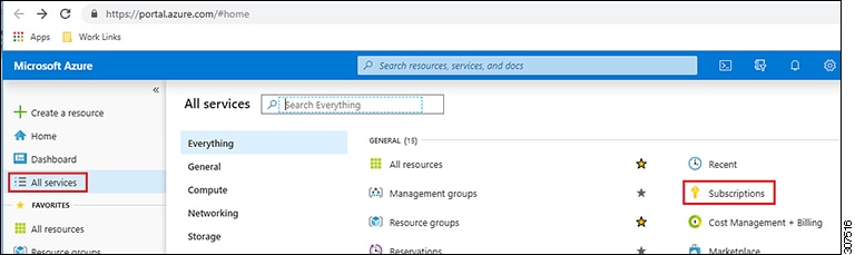
From the main Azure management portal page, click the All services link in the left nav bar, then click the Subscriptions link.
-
In the Subscriptions page in the Azure management portal, click the subscription account that you created.
The overview information for that subscription is displayed.
-
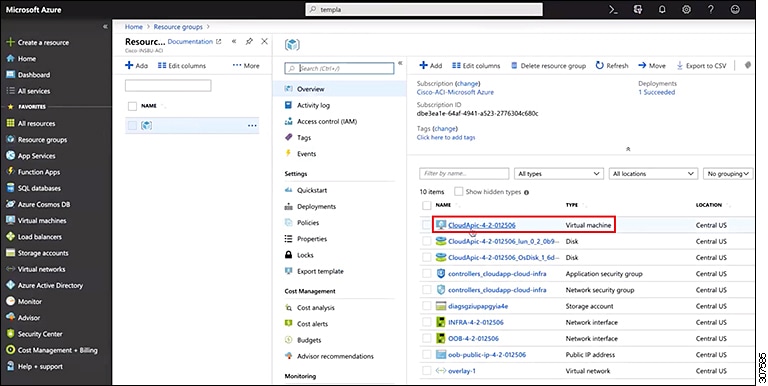
From the overview page for that subscription, locate the Resource groups link in the left nav bar and click that link.
The resource groups for that subscription is displayed.
-
Choose the resource group that you chose or created in the Custom deployment page in Deploying the Cloud APIC in Azure.
The overview information for that resource group is displayed.
-
In the overview page for the resource group, locate your CCR VM instance (shown as Virtual machine under the TYPE column), and click the link for that VM instance.
The CCR VM instance will have a name with a ct_routerp_region_x_0 format, where:
-
region is the managed region (for example, westus, westus2, centralus, or eastus)
-
x is the CCR count, starting from zero
For example: ct_routerp_centralus_0_0 or ct_routerp_centralus_1_0
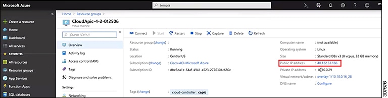
The overview information for the CCR VM instance is displayed.
-
Locate the Status field at the top left area in the page.
-
If you see the text Creating in the Status field, then the CCRs are not fully deployed yet.
-
If you see the text Running in the Status field, then the CCRs are fully deployed.
|

 Feedback