Workbench

The Workbench is used to create and modify a lab's topology and to interact with the lab simulation. To open a lab in the Workbench, find the lab in the Lab Manager page and, depending on the Lab Manager's view, click on the tile (tiles view) or the workbench link (list view) associated with the lab.

Adding Nodes to a Lab

Before you begin

Open the lab that you want to edit in the Workbench by clicking on its tile on the Lab Manager page.

Procedure


Step 1

Click the Add Nodes drawer in the Workbench to open it.

In a new lab or a lab with no nodes, the Add Nodes drawer will already be open by default.
Step 2

Drag-and-drop a node type from the Add Nodes drawer onto the lab to add a node of that type to the lab's network topology.

Step 3

Repeat the previous step for each node that you want to add to the lab.


Starting, Stopping, and Wiping Nodes

When starting a lab simulation, CML starts a virtual machine (VM) for each node in the lab. Similarly, stopping a lab or wiping a lab affects all of the nodes in the lab. If you want to start, stop, or wipe individual nodes, you can do that in the Workbench. If you are running a simulation, you can start, stop, or wipe individual nodes in that simulation without stopping the entire lab or interrupting the other nodes in the simulation.

Procedure


Step 1

In the Workbench, select the node.

Step 2

Click the Simulate tab in the bottom pane of the Workbench.

Step 3

Click the Start, Stop, or Wipe Node button in the Simulate pane.

Caution 

Pay attention to the button labels. If you have not selected a single node, then the buttons in the Simulate pane will indicate Start Lab, Stop Lab, or Wipe Lab. Clicking on these buttons will apply the action to all nodes in the lab.

Start

Starts a VM associated with the node.

Starting a node allocates a VM for the node if one does not already exist. If the node has been started before, it reuses the already-allocated resources, such as disk images and MAC addresses.

Stop

Stops the VM associated with the node.

Stopping a node releases its memory and CPU resources. A stopped node is still present on the CML server and retains its disks and other properties for use when it is started again.

Wipe Node

Deletes all state associated with the node.

Wiping a node removes all state and properties associated with the node from the CML server. The next time you start the node, CML will re-create it and assign new MAC addresses, disks, and other resources. Since a wiped node has no pre-existing state, the node will load its bootstrap configuration the first time it is restarted. The node's bootstrap configuration can be found in the Edit Config pane of the Workbench.

Figure 1. The Workbench's Simulate pane with Start, Stop Lab, and Wipe actions

Screenshot: the Workbench's Simulate pane, showing Start, Stop, and Wipe actions
Depending on the node's status, one or more of the buttons in the node's Simulate pane may be disabled. The Start and Wipe Node buttons are only enabled when the node is already stopped. The Stop button is only enabled if the node has been started.

Deleting Nodes

Before a node can be deleted, the node's associated state must first be removed. If you have ever run a simulation with the node, then the node's state persists even when the simulation stops. CML requires you to wipe a node before deleting it to ensure that you do not accidentally delete a node that still has some associated state that you want to preserve.

Procedure


Step 1

In the lab Workbench, select the node to be deleted.

Step 2

Click the Node Info tab in the bottom pane of the Workbench.

Step 3

Click the Delete Node button in the Node Info pane.

A popup confirmation dialog is shown.
A node can only be deleted if it is currently stopped and has no associated state on the CML server. If the Delete Node button is disabled, first stop and wipe the node. See Starting, Stopping, and Wiping Nodes.
Step 4

Click OK in the dialog to confirm that you want to delete this node and its connections from the lab.


Creating Links

Links function like a physical wire that connects two interfaces. Link the nodes in your lab to create the desired network topology.

Procedure


Step 1

In the Workbench, hover over the desired source node for the new connection to activate the action ring for the node.

Step 2

Press and hold the mouse button on the blue link button.

Example:

Figure 2. G

Screenshot: the link action in a node's action ring in the the Workbench

Note: if the mouse cursor changes to a cancel icon when you hover over the link button on the action ring, the Workbench is indicating that that the source node has no more available interfaces. You will not be able to create any additional connections to or from this node until an existing interface is freed.

Step 3

While holding the mouse button, drag away from the source node to start creating a connection.

Step 4

Hover the mouse over the desired destination node for the connection and then release the mouse button.

The currently selected node will be highlighted in blue.

Example:

Figure 3. Selecting the destination node for a link in the Workbench

Screenshot: selecting the destination node for a link in the Workbench
The Workbench pops up an interface selection dialog.
Note: the currently selected node should be highlighted in blue. If the selected node is highlighted in red, and the mouse cursor changes to a cancel icon, the Workbench is indicating that the destination node has no more available interfaces. You will not be able to create any additional connections to or from this node until an existing interface is freed.
Step 5

Select the desired interface on the Source and Destination nodes in the dialog. Alternatively, you can just click the Use Next Available (interface) button, and the connection will be created with the first unused interface on each node.

Example:

Figure 4. The unused and provisioned interfaces for nodes in the interface selection dialog

Screenshot: the unused and provisioned interfaces for nodes, as shown in the interface selection dialog for a new link

Rules for Creating Links and Interface Overprovisioning

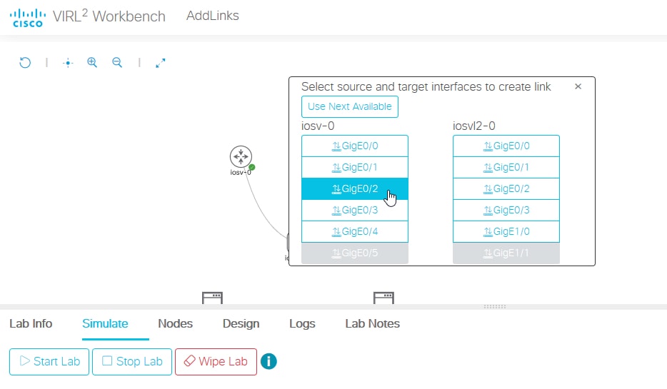
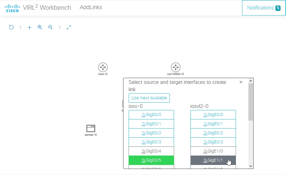
While you can create or redirect links even when the nodes involved in the link are running as part of a simulation, it is only possible to create a link if the nodes at either end of the link each have an unused interface available. Once a node has been started, the number of interfaces allocated to that node cannot be changed until the node is stopped and wiped. This restriction means that link creation and interface creation behave differently once you have started a node.

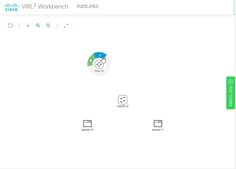
If you add a node to the canvas and have not started it yet, or if you have wiped a node and not started since wiping it, the Workbench automatically adds additional interfaces to a node to accommodate new links. You may also add extra interfaces directly to a node. Each node definition has a maximum possible number of 
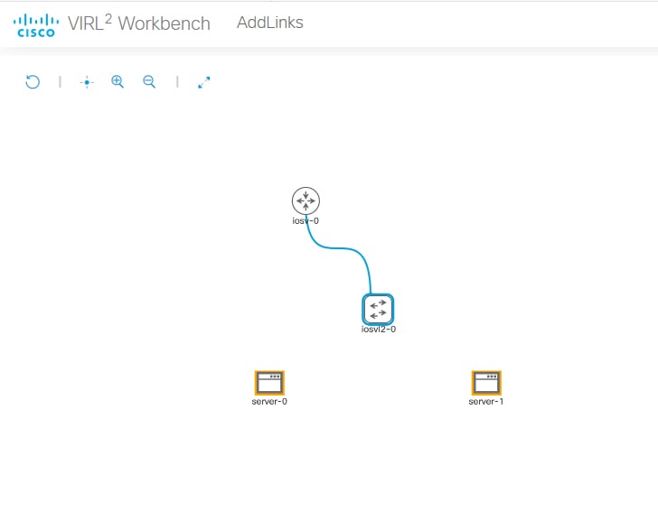
interfaces. If the node is not at the maximum number of allocated interfaces for its node definition, you can select it as the source or destination of a link. If all of the allocated interfaces are used by existing links, the Workbench permits you to select an unallocated interface for the connection, and it allocates that interface to the node when you create the connection. If the node already has its maximum number of interfaces allocated, and all of the interfaces are in use, then it is not possible to create a new link with that node.

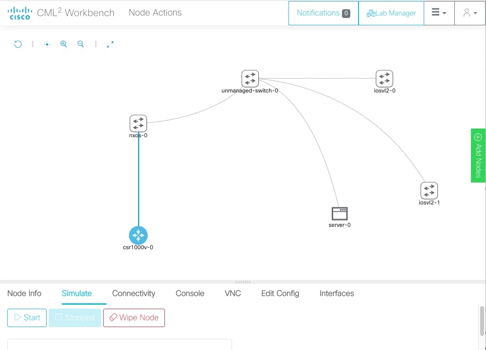
If a node is currently running as part of a simulation, or if the node is stopped but has associated simulation state that has not been wiped, then the number of interfaces allocated to that node cannot be changed. If at least one of the interfaces allocated to the node is unused, then you can select it as the source or destination of a link. If all of the interfaces allocated to the node are used by existing links, then it is not possible to create a new link with that node even if the node has fewer allocated interfaces than its maximum number of allowed interfaces. Before you can add a link or interface to such a node, you must stop and wipe the node.


Tip

To avoid having to stop a node in your simulation or to recreate its state after wiping it, you may want to overprovision interfaces on the nodes in your labs. Overprovisioning interfaces means allocating more interfaces on a node than it needs for the existing links in the topology. If you overprovision the interfaces on the nodes in your lab, each node has at least one unused interface when you first start the simulation. These extra interfaces enable you to add additional nodes and links to your lab later without having to stop or wipe any of the existing nodes in the lab.


Because interfaces consume system resources, CML only allocates additional interfaces to a node when the interfaces are needed for a new link. Each node definition has a default initial number of interfaces. When you first drag-and-drop a node into the lab, the node will have the default number of interfaces allocated to it. In smaller topologies, the default number of interfaces may create some modest overprovisioning, but if you want to overprovision interfaces in your lab, you should check all nodes before starting the lab to ensure that each one has enough unused interfaces allocated to each node.


Tip

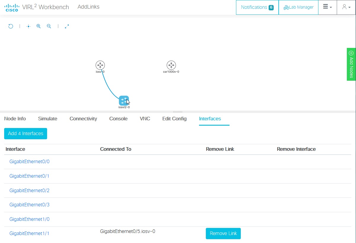
If you cannot create a connection to a node, select the node and then click the Interfaces tab in the bottom pane of the Workbench. If the button in the top-left of the Interfaces pane indicates Max Interfaces Reached, then the node has reached the maximum number of interfaces possible for that node type. If the button is disabled but indicates Add # Interfaces, then additional interfaces can be added to the node, but the node must be stopped and wiped first.


Adding Interfaces to a Node

CML automatically allocates interfaces to a node to accommodate new links. It is not necessary to manually add interfaces unless you want to overprovision interfaces for the node. See also Rules for Creating Links and Interface Overprovisioning.

Procedure


Step 1

Select a node in the Workbench.

Step 2

Click the Interfaces tab in the bottom panel of the Workbench.

Example:

Figure 5. The Interfaces panel for a node in the Workbench.

Screenshot: the Interfaces panel for a node in the Workbench
Step 3

Click the Add # Interfaces button to add additional interfaces.

The button label shows how many interfaces will be added. By default, interfaces are added in groups of four, and the button shows Add 4 Interfaces. Each node definition has a maximum number of interfaces, and if the node can support fewer than four additional interfaces, the button label will change to indicate how many more interfaces can be added. If the node already has the maximum number of interfaces supported by its node type, then the button will be disabled and indicate Max Interfaces Reached.


Overprovisioning Interfaces with Link Creation

When creating links between nodes, the Workbench displays the interface selection dialog. Instead of clicking the Use Next Available button, you can select specific source and destination interfaces. The Workbench will allocate interfaces to the node to accommodate the new link, if necessary. If you always connect links to a node by using the next interface in sequence, once the default number of interfaces for the node are used, all of the interfaces allocated to the node will be used by a link. That is, when the node is started, it will have no interface overprovisioning, and no interfaces will be available for adding new links to that node at simulation time.

Instead of adding interfaces to a node, you can also overprovision interfaces on a node while creating a link. Simply skip one or more interfaces in the interface list when you create a link.

Procedure


Step 1

Follow the instructions for creating a link until the interface selection dialog is shown.

Step 2

Select an interface from the interface list, skipping one or more unused interfaces.

Example:

For example, if you want to ensure that each node has five unused interfaces, you can start all of your interface selections at the sixth interface in the list, as shown. In this example, connect GigE0/5 to GigE1/1.

Figure 6. Interface selection dialog for a new link in the Workbench

Screenshot: interface selection dialog for a new link in the Workbench
The link is created, and all interfaces up to the selected interface are allocated on the node.
Step 3

You can verify the number of allocated but unused interfaces by selecting a node and clicking on the Interfaces tab in the bottom pane of the Workbench. The Interfaces pane shows allocated interfaces. The interfaces with no listed connections are available for use.

Example:

In this example, interfaces GigE0/0 - GigE1/0 are allocated but unused on iosvl2-0. These overprovisioned interfaces will be available for use when the simulation is running.

Figure 7. The Interfaces pane for a node in the Workbench

Screenshot: the Interfaces pane for a node in the Workbench
\
Tip 

If you select the last interface for a node in the interface selection dialog, the maximum number of interfaces for that node's definition will be allocated to the node.


Starting a Simulation

Before you begin

Open the lab that you want to start in the Workbench by clicking on its tile on the Lab Manager page.

Procedure


Step 1

First, ensure that no nodes are selected by clicking on an empty area of the Workbench.

Step 2

Optional: Select the Design tab at the bottom of the Workbench page.

Step 3

Optional: Click the Build Initial Bootstrap Configurations button in the Design panel.

You can also build configurations on an individual node by selecting the desired node and then clicking the Build Initial Bootstrap Configurations button.

CML generates a basic startup configuration for all nodes in the topology.
Step 4

Select the Simulate tab at bottom of the Workbench window.

Step 5

Click the Start button.

CML will start the simulation for the lab. Note that the Workbench will provide visual feedback, indicating each node's status. A node is finished booting and ready for use when the Workbench displays a green dot next to it.

Connecting to a Node's Console

Once a simulation is started, you may connect to the console or, for applicable nodes, the VNC server for a node.

Procedure


Step 1

Hover over the desired node to activate the node's action ring.

Step 2

Click the Console button on the action ring to open the node's Console pane at the bottom of the Workbench.

Figure 8. Open Console Node Action

Screenshot: open console action on a node's action ring.
Step 3

Click the Open Console button in the Console pane at the bottom of the Workbench to activate the console connection.


Stopping a Simulation

Lab simulations are not stopped automatically. A lab simulation will continue to run and consume resources even if you close the Workbench page for a lab or log out of the UI.

Procedure


Step 1

First, ensure that no nodes are selected by clicking on an empty area of the Workbench.

Step 2

Select the Simulate tab at the bottom of the Workbench window.

Step 3

Click the Stop button.


CML will stop the simulation for this lab. The lab's nodes will be stopped, and the Lab Manager will no longer show this lab as running.