External Connectivity in Cisco Modeling Labs

Basic Node Access

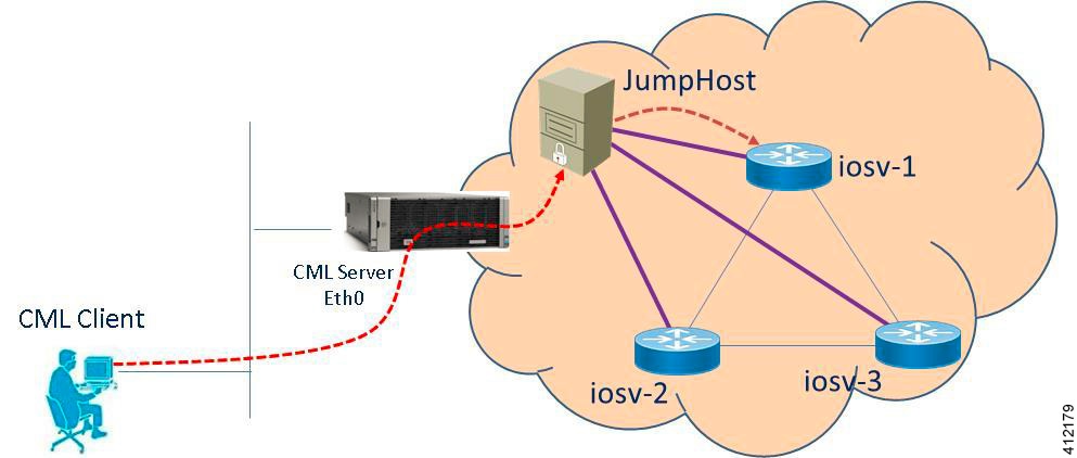
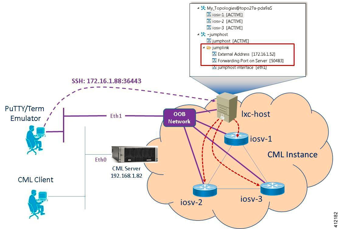
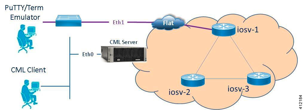
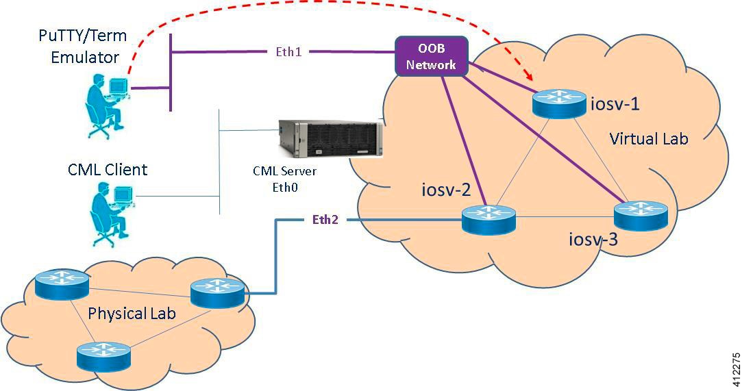
For simple network topology simulations, access to simulated nodes can be conducted through the Cisco Modeling Labs server’s management interface , Ethernet0. This is useful for simulation scenarios that do not require connection to external devices, and leverages the Cisco Modeling Labs server's management interface for communications with the virtual devices. No Flat or SNAT interfaces are configured or referenced, and no option is specified within the project’s Properties > Topology > Management Network setting. In this minimal configuration, connections to the virtual nodes instances are facilitated through the Cisco Modeling Labs’s client Server management option.

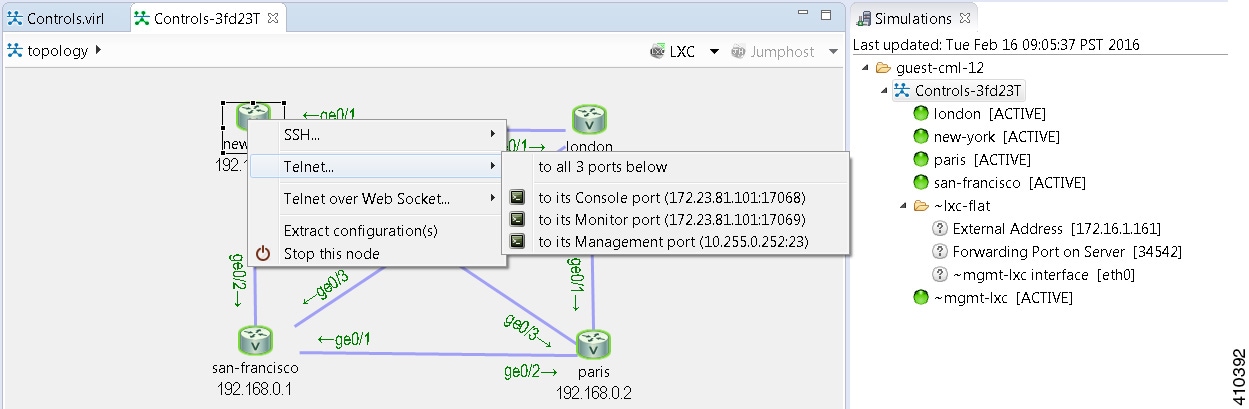
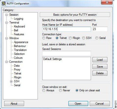
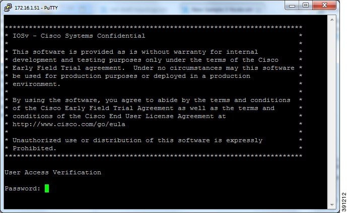
Telnet via Cisco Modeling Labs Client Console

The Cisco Modeling Labs client provides an integral access method to running node simulations. In the Simulation perspective, highlight an ACTIVE node within the Simulations view and performing a right-click operation expands a session start menu. Positioning the cursor over Telnet triggers a popup menu from which the Console, Monitor, or Management ports may be selected. Alternatively, highlighting a node on the canvas and performing a right-click will present the same set of options, as shown.
Figure 1. Start a Telnet Session


Within the Cisco Modeling Labs client’s console, a Telnet session through this node’s console port is started.

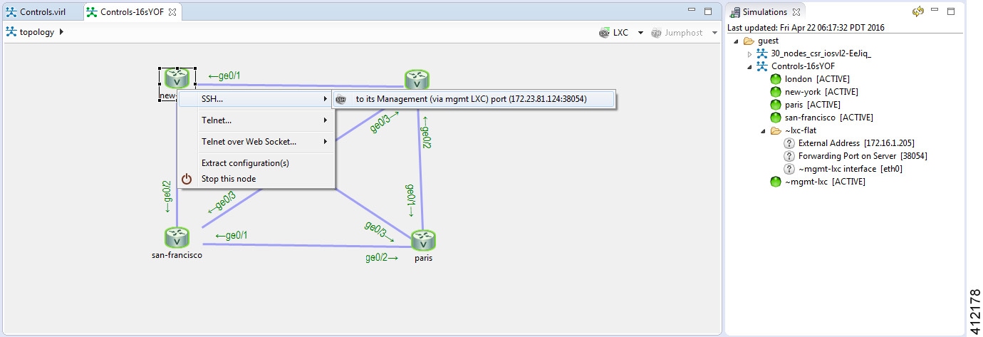
SSH via Cisco Modeling Labs Client Console

Using the same scenario as for Telnet, an SSH session may be used. In the pop-up menu, a SSH session may be selected. Positioning the cursor over SSH triggers a popup menu from which the Management port may be selected. Alternatively, highlighting a node on the canvas and performing a right-click will present the same set of options, as shown.
Figure 2. Start a SSH Session


A secure shell session is then launched to an internal jumphost (a lightweight Linux-based virtual machine running within the simulation) from which a Telnet session is started to the highlighted node’s Management interface. The IP_Addr:Port_ID combination is the same for each of the nodes within the running simulation, and represents the JumpHost as an intermediate session proxy. The Cisco Modeling Labs client will initiate the connection via the Cisco Modeling Labs management interface (Eth0) to the intermediate jumphost, and then facilitate the subsequent Telnet connection to the targeted node in a single operation.
Figure 3. SSH Session via JumpHost


Access via User Workspace Management Interface

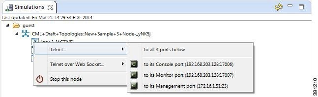
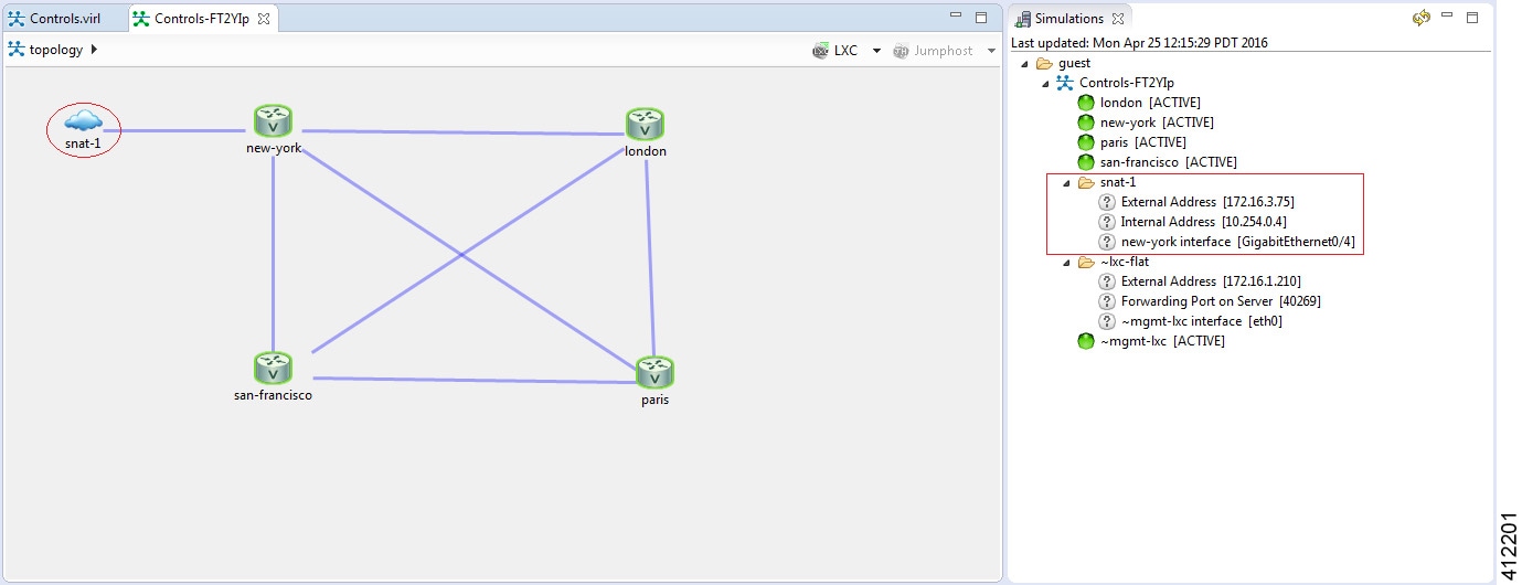
Another option is to access the nodes in a running simulation through the User Workspace Management interface via a web browser. After entering log in credentials, click the My Simulations option to view a list of running simulations. Select the applicable simulation to view a list of nodes comprising the running simulation. To access a node, click one of the ports icons, representing Serial-0, Serial-1, or the Management port, associated with the desired node. As shown, a corresponding session is started for the selected node.

Figure 4. Using the User Workspace Management Interface for Node Access


External Connectivity to a Node

Depending on how the Cisco Modeling Labs environment has been set up by the system administrator, you may have several ways to externally connect to the nodes in a running simulation.

  1. Bypass the Cisco Modeling Labs client and connect directly to nodes via Out of Band Management IP access using FLAT

    If enabled by the system administrator, when designing your virtual network, you can specify that you want all nodes to be configured on a reserved management network. All management interfaces are connected to a shared management network segment known as FLAT. This set up will allow you to bypass the Cisco Modeling Labs client and connect directly via Telnet to the nodes.

  2. Connecting to external devices using FLAT Inband access

    When enabled, you can configure your virtual topologies to connect and pass data-plane and control-plane packets to one or more external devices such as routers or traffic generators during a simulation. Since FLAT is a Layer-2 solution, the IP addresses in your topology are reachable externally. The L2 External FLAT tool in the Cisco Modeling Labs client GUI is used to enable this option.

    Note

    Your simulation continues to be driven through the Cisco Modeling Labs client GUI by communicating with the Cisco Modeling Labs server at its IP address that is bound to the relevant management port.


  3. Connecting to external devices using SNAT Inband access

    As an alternative to Inband access using FLAT, you can set up the Static NAT (SNAT) approach. SNAT is a Layer-3 solution that leverages the use of an internal SNAT router to hide the IP addresses in your topology. This router, internal to the Cisco Modeling Labs server, translates IP addresses inbound and outbound which means that the addressing schemes used on the virtual topology are not propagated outside the virtual network.

    When configured, an internal and an external address are assigned to the SNAT-assigned interface on the nodes. For example, configuring 10.11.12.1 as the internal address, and mapping it to 172.16.2.51 externally. Traffic sent to 172.16.2.51 will be translated to the correct internal address and presented to the appropriate node.

    The L3 External SNAT tool in the Cisco Modeling Labs client GUI is used to enable this option.

    Note

    Your simulation continues to be driven through the Cisco Modeling Labs client by communicating with the Cisco Modeling Labs server at its IP address that is bound to the relevant management port.


Node Access via an External Terminal Client

There are situations when an external terminal client may be preferred over the Cisco Modeling Labs client for accessing the nodes’ console. Factors may just be familiarity, or to capture and save session commands and respective responses to configuration changes.

Standard Telnet Sessions

By using the same socket combination used by the Cisco Modeling Labs client initiated sessions, a Telnet session may be launched from a Telnet client residing on the Cisco Modeling Labs client workstation, or another workstation. Using the Cisco Modeling Labs client, hovering the cursor over Telnet triggers a popup menu from which either the Console or Monitor ports may be noted. A Telnet session is directed to the Cisco Modeling Labs management IP address using the assigned port to the serial console port.

Note

The TCP port is a transient value generated upon spinning up the virtual node. If the party accessing the nodes does not have a Cisco Modeling Labs project login account, the project owner/administrator will need to provide the node access socket details.

SSH Sessions

If using an external terminal emulator, an SSH session directed to the JumpHost socket will open a terminal session on the JumpHost. After entering user credentials (same as those for the Cisco Modeling Labs server), the logged in user will then manually initiate a Telnet session to the desired node using its management interface.

Out-of-Band Management Sessions via the Flat Interface

The Cisco Modeling Labs client is not required to access nodes within a running project simulation. When configured, the out-of-band (OOB) management network interface for the running nodes may be accessible by external (physical) devices. A variety of methods employ a Layer-2 connection through the Ethernet1 interface, designated as Flat. This can be useful when you want to grant access to nodes within a running project to users without Cisco Modeling Labs credentials.

The available options are:
  • Use Telnet to bypass the Cisco Modeling Labs Client: You can configure a shared OOB management interface on each of the topology’s nodes. You can do this by selecting Shared Flat Network as the Management Network option for the topology under Properties > Topology.
    Figure 5. Shared Flat Network Option


    Selecting the Shared Flat Network option enables OOB external network access to all devices within the topology. This management network option assigns an IP address from the Flat network pool to each of the node’s designated OOB Management interface (GigabitEthernet0/0), and presents that network to the Cisco Modeling Labs' Flat interface (Eth1).

    Note

    All running projects configured with Shared Flat Network as the Management Network will have their constituent nodes exposed to the Flat network interface with an IP address assigned from the provisioned Flat subnet range. As such, project users are able to access operating nodes beyond those associated with their specific project.
    For management stations directly attached to this network, a node is accessed by initiating a standard Telnet session to the OOB management interface assigned during the topology start-up process. The Cisco Modeling Labs client, via the Simulations perspective or the User Workspace Management interface may be used to find out the IP addresses assigned to the OOB management interface for each of the running nodes.
  • Use SSH via Jumphost: You can use SSH to access a node's OOB management interface via the Flat Ethernet1 interface, where the session is directed to the project-level Jumphost.
    Figure 6. Using an SSH JumpHost in a Simulation


    Accessing the simulated nodes via SSH using an external terminal emulator will require a two-step process. The jumphost represents a minimal Linux-container that terminates the SSH sessions. After entering user credentials, the logged in user may then manually initiate a Telnet session to the desired node using its management interface, provided that remote access has been enabled in the devices’ configurations. A jumphost implemented at the Project level will have accessibility to any simulation running within the user’s project space. Implementing an LXC management node creates a jumphost within the simulation. The following figure shows where enabling a node with the Use an LXC Management Node option when defining the topology’s properties results in an ~lxc-flat object being launched within the simulation.
    Figure 7. Using an LXC Flat JumpHost in a Simulation


  • Use Private Management Networks: When the simulation’s Management Network is set as Shared Flat Network, all nodes within the topology are assigned an IP address from the pool provisioned for the Flat network interface (Eth1) and are accessible to any user attached to the Eth1 interface. To provide additional isolation from other users, the topology may be optioned with an internal OOB management network. When set for private management, the simulation-nodes’ OOB interfaces are assigned, by default, addresses from the 10.255.0.0/24 range.

    A private OOB management network may be established at the project-level with multiple simulations within a common project or per simulation. When a private OOB management network is implemented, access to the simulation’s virtual nodes is limited to the Cisco Modeling Labs client, or via SSH to the jumphost when external terminals are used.

Set Up a FLAT Network for Out of Band (OOB) Management Access

By using an out-of-band (OOB) network connection to the Cisco Modeling Labs simulation, you can connect an external application to the Management port of any router node in the simulated network. All management ports will have an IP address on the OOB network, which is a separate network from the other interface IP addresses.

Before you begin

  • Ensure that you have installed a third-party application for Telnet connections, such as PuTTY.

  • Ensure that FLAT connectivity has been enabled by the system administrator.

Procedure


Step 1

Log in to the Cisco Modeling Labs client.

Step 2

Verify you have connectivity to the Cisco Modeling Labs server.

Step 3

Open the Design perspective, if it is not already open.

Step 4

Open an existing topology or create your network topology. See Create a Topology for information on how to do this.

Step 5

Configure the OOB management network.

  1. Click on the Topology Editor canvas.

  2. Choose Properties > Topology.

  3. Locate Management Network and select Shared flat network from the drop-down list.


The Shared flat network option is what enables the OOB connectivity.
Step 6

From the toolbar, click the Build Initial Configurations tool.

Note 
For the purpose of this task, you may retain the default settings.
Step 7

After the build phase is completed, initiate the simulation by clicking the Launch Simulation tool in the toolbar, and then change to the Simulation perspective.

Step 8

(Optional) Enter the ping command on the PC to confirm that the management port on a running node can be reached.

  1. In the Cisco Modeling Labs client simulation, select a node and display the IP address for its management port. In this example, the IP address for the node management port is 172.16.1.51.


  2. In the PC command window, enter the ping command to target the node management port identified in Step 8a.


Step 9

(Optional) In the Cisco Modeling Labs client simulation, connect to a console port on a node and confirm the management network IP address exists. Enter the show ip interface brief command to display the IP addresses. For this example, use the IP address 172.16.1.51.


Step 10

Launch and configure a terminal emulator for a Telnet connection to the node management port. In this example, the PuTTY application is used.

  1. Launch the PuTTY application.

  2. In the PuTTY Configuration window, enter the IP address for a Telnet connection to the management port. In this example, the IP address for the node management port is 172.16.1.51.


  3. When successful, a Telnet window opens and the router console information is displayed.


Add an Additional FLAT Network to a Simulation

The following procedure describes how to configure a second FLAT network to your simulation. A FLAT network uses Layer 2 connectivity, in which the IP address information about your virtual network can be viewed externally.

Procedure

Step 1

With your topology open on the canvas, click the L2 External (FLAT) icon to add another FLAT network to your topology, as shown.

Step 2

Click the FLAT network just added, and in the Extensions tab in the Properties view, click the Add new extension icon.

The Edit extension dialog box is displayed.
Step 3

Add the following details for the new extension and click OK.

  • Key: host_network

  • Value: flat1

  • Type: String

Note 
You must add this new extension for the second FLAT network, as a second interface is not permitted in the same subnet. This FLAT network is in the flat1 subnet.
Step 4

From the toolbar, click the Build Initial Configurations tool.

Note 
For the purpose of this task, you may retain the default settings.
During the simulation phase, the system automatically assigns an IP address to the node interface that is connected to the FLAT cloud.
Step 5

After the build phase is completed, start the simulation by clicking the Launch Simulation tool in the toolbar, and then change to the Simulation perspective.

The IP addresses assigned to each of the interfaces in the FLAT network and connected to each node, are displayed in the Simulations view. These IP addresses are automatically applied to the nodes when they become active.
Step 6

Regarding the node that has two FLAT network connections, when its state has changed to [ACTIVE], log in to said node.

Step 7

Enter the command show ip interface bri to view all interfaces available to the node.

You can see that the node has a connection into each of the external FLAT connectivity networks, 172.16.1.196 and 172.16.2.53.


In-Band Management Sessions via a Flat Interface

Managing nodes via the Cisco Modeling Labs client or using terminal emulator sessions via OOB management interfaces work well when the access is exclusively used for management plane interactions. When external connectivity will be used for both management-plane and data-plane traffic exchanges with external devices, an In-Band management solution may be warranted. As shown in the following figure, the Flat (Eth1) interface is associated with an interface on the new-york node, to which an IP address from the Flat-interface address pool is assigned.

Figure 8. In-Band Management Connections


Within the Cisco Modeling Labs client’s Design perspective, an L2 External (FLAT) object is placed on the canvas and a link connection is drawn between the resultant flat-1 icon and a node, as shown.
Figure 9. Enabling Bridged Connections to External Devices


Using the L2 External (FLAT) object precludes the simultaneous use of the Out-of-Band management option. The Management Network option within Properties > Topology is not defined (<not specified>) as shown above.

During the topology’s launch phase, an IP address from the range provisioned for the Flat (Eth1) interface (by default, 172.16.1.0/24) is assigned to the associated interface on new-york. The externally attached terminal or management device is then manually configured with an unused IP address within this scope. An alternative option is to enable DHCP services on the node as to offer an IP address to the attached workstation.


Note

In multiuser deployments, consideration must be given to DHCP scope and exclusion ranges applied to nodes within simulation environments and to coordinate the assignment ranges being facilitated by the Cisco Modeling Labs server during topology build/launch phases. Otherwise, multiple agents assigning addresses from overlapping pools might result in duplicate address assignments.

Set Up a FLAT Network for Inband Access

Managing nodes via the Cisco Modeling Labs client or using terminal emulator sessions via OOB management interfaces work well when the access is exclusively used for management plane interactions. When external connectivity is used for both management-plane and data-plane traffic exchanges with external devices, an In-Band management solution may be required.

The following procedure describes how to connect your virtual network topology to physical devices that are external to the Cisco Modeling Labs server environment. In this procedure, you will be configuring a FLAT network. A FLAT network uses Layer-2 connectivity in which the IP address information about your virtual network can be viewed externally.

Before you begin

  • Ensure that the system administrator has configured the Cisco Modeling Labs server to allow FLAT connections.

  • Ensure that you obtain the IP address of the default gateway from the system administrator.

  • Ensure that you have the IP address of the external device to which the nodes will connect.


Note

We recommend that you first draw your intended design, and then label the devices with the appropriate IP addresses.

Procedure


Step 1

Log in to the Cisco Modeling Labs client.

Step 2

Verify you have connectivity to the Cisco Modeling Labs server.

Step 3

Open the Design perspective, if it is not already open.

Step 4

Open an existing topology or create your network topology. See Create a Topology for information on how to do this.

Step 5

Click on the canvas to open the Topology tab in the Properties view and ensure that Management Network displays <not specified>.

Step 6

From the Palette view, under General, click the L2 External FLAT tool, and then click the canvas to add one FLAT cloud network icon to each corresponding node icon on the canvas.

Step 7

From the Palette view, under Tools, click the Connect tool and connect the L2 External FLAT to the desired nodes.

Note 
L2 External FLAT connections can only be assigned to one interface on one node.
Step 8

From the toolbar, click the Build Initial Configurations tool.

Note 
For the purpose of this task, you may retain the default settings.

The system automatically assigns an IP address to the node interface that is connected to the FLAT cloud during the Simulation phase, not the Build phase.

Step 9

After the build phase is completed, start the simulation by clicking the Launch Simulation tool in the toolbar, and then change to the Simulation perspective.

Step 10

Log in to the node that is connected to the FLAT network when its state has changed to ACTIVE.

Step 11

View the IP address assigned to the FLAT network and determine if it is on the same subnet as the gateway IP address provided by your system administrator. The L2 external address for each node can be viewed from the Simulations view or from each individual node.

  • If yes, continue to Step 12.
  • If no, advise your system administrator and request the correct gateway IP address.
Step 12

If the external device is on a different subnet, define a default gateway or a broadcast domain that points to the IP address of the gateway that the system administrator supplies.

Prior to completing this step, if you do a show route, you will see that no default gateway is defined in the node. This is the default set up. This step allows you to inform the node what path to take in order to reach the external environment via the gateway. An alternative to defining a gateway or static route, with IOSv devices, is to enable DHCP on the interface used for external connectivity.
Note 
Not all virtual images support DHCP. Check the supported features for the virtual images to determine which ones do support DHCP.
Step 13

Test the connection by pinging from the node to the external (physical) device. If required, turn on debug ip icmp or use the tracert command to see the progress through the network.

Note 

You must repeat steps 10-13 for each node that is connected to the FLAT network.

If the ping does not work, confirm with your system administrator that the Cisco Modeling Labs server is configured to support FLAT connectivity and that the gateway IP address you have been provided is correct.

If these items are correct, ping to each of the key devices in the path to determine where the failure occurs and notify your system administrator of the failure source if it is outside your Cisco Modeling Labs environment.


Interconnect Topologies in Physical Labs via a Flat Interface

A Flat interface may also be used to interconnect a group of physical lab devices to nodes running within a simulation.

By default, the node’s interface associated with the Flat object is assigned an IP address from the range provisioned to the Cisco Modeling Labs’ Ethernet1 interface during server installation. This is allotted when the node is spun up by OpenStack when the simulation is launched. Once fully active, the assigned interface address may be adjusted to meet the addressing requirements of the external environment (or the external device’s interface is configured with an appropriate address to interact with the node.) After confirming Layer-2 connectivity between the physical/virtual nodes, implement the necessary (static or dynamic) routing in both physical and virtual lab environments to complete the integration.

Access Multiple Nodes via a Flat Interface

The L2 External (FLAT) object may be assigned to only one interface on one node. When topology scenarios demand Layer-2 connections to multiple nodes, additional L2 External (FLAT) objects may be used on the canvas with the associated link relationship to the associated node.
Figure 10. Multiple Flat Network Associations


When a simulation is launched, an IP address from the Flat (Ethernet1) external address pool is assigned to the respective node interfaces connected to the external icon. While the example functionally matches that of the OOB_Management configuration, it differs in that the interfaces reserved for OOB (GigabitEthernet0/0) are not used. Instead, the next available infrastructure interface is selected for use (or manually allocated).

Connect Multiple Networks across a Single Flat Interface

Multiple Layer-3 networks may be interconnected between physical and virtual nodes using a single flat interface. This is facilitated by the use of the Cisco IOSvL2 node within the simulation, with the external facing interface configured as an 802.1Q trunk. The corresponding trunk configurations are applied to the attached physical device’s interface, as shown. Each Layer-3 network is represented as a VLAN traversing this Layer-2 trunk.
Figure 11. Extending VLANs across Cisco Modeling Labs' Flat (Eth1) Interface


Note that the AutoNetkit process may not completely provision this application, and manual configurations may be necessary to enable the external connection as a trunked interface. Special consideration may be required for Cisco Modeling Labs deployments on top of ESXi when extending VLANs between an IOSvL2 node and an external device. Whether deployed with distinct ESXi vSwitches and dedicated pNICs or a common vSwitch with a shared/trunked pNIC, the ESXi Port Groups associated with the Flat interface must be set to carry 802.1Q tagged frames. Using the vSphere client (or vCenter management station) to access the ESXi server, the host’s Networking > Configuration page is accessed. Edit the Port Group properties of the Flat interface to pass All (4095) VLAN IDs, as shown. If the Flat1 interface is to be used in a similar manner, it should also be enabled to carry all VLAN IDs.
Figure 12. Setting the ESXi Port Group to Support VLANs


Note

The upstream (physical) switch interface should not have the BPDU_Guard feature enabled on the associated interface(s) as to prevent any BPDUs originating from virtual nodes from triggering an interface-shutdown.

Employ Multiple Flat Interfaces

There are simulation scenarios that may necessitate multiple Layer-2 connections to external devices, as shown.
Figure 13. Employing Multiple Flat Interfaces to External Devices


Applications that necessitate multiple flat network interfaces may include:
  • Traffic generated by an external source that crosses the virtualized network to another external destination device.

  • Integrating multiple, physical lab topologies (representing access-networks) to a simulated core topology.

  • Interconnecting multiple virtual lab scenarios or external virtual machines to a simulated core topology.

  • Scaling Cisco Modeling Labs topology sizes by interconnecting multiple Cisco Modeling Labs instances across separate servers.

The Cisco Modeling Labs server offers a second bridged interface to enable such test designs. Adding L2 External (FLAT) objects will, by default, be associated to the Flat (Eth1) interface. This default allocation may be manually overridden by editing the object’s properties as to use the server’s Flat1 (Eth2) interface.

This change is done by selecting the L2 External (FLAT) icon on the canvas. Within the Properties view, choose the Extensions tab and click Add [+], as shown.
Figure 14. Editing L2_External(FLAT) Object Properties


Within the Edit Extension dialog box, add the following details for the new extension, and click OK.
  • Key: host_network

  • Value: flat1

  • Type: String

When the simulation is launched, an IP address from the Flat1 external address pool is assigned to the respective node interface connected to the L2 External (FLAT) icon. The Simulations view shows the flat-1 and flat-2 objects and their attributes.
Figure 15. Displaying Properties of Running Flat Interfaces


Examination of the flat-2 object shows its association to the flat1 Host Network, and the respective iosv-1 interface (GigabitEthernet0/3) assigned an IP address from the Flat1 address pool (172.16.2.0/24 in the example). As additional L2 External (FLAT) objects are added to the canvas, they may remain associated with the default flat interface or edited as described to be associated with the flat1 interface.

Employ OOB Management with External Devices

When the Shared flat network is selected as the Management Network for OOB_Management, the Flat (Eth1) interface is associated with the GigabitEthernet0/0 interfaces for each of the nodes in the topology simulation. If external devices are also to be integrated using a flat interconnection, the Flat1 (Eth2) and associated IP address range must be used, as shown.
Figure 16. Using OOB Management with Flat-interconnect External Devices


When the L2 External (FLAT) object is inserted into the topology, its properties must be edited as described in the previous section.

Important

In these scenarios, if the L2 External (FLAT) object is not edited to use the Flat1 interface, the Cisco Modeling Labs client’s Build process will fail, reporting overlapping use of the Flat interface.

Interconnect External Devices via a SNAT Interface

The Static Network Address Translation (SNAT) interface enables communications between running nodes and external devices using Layer-3 services via an internal (OpenStack) virtual router. Using the L3_External (SNAT) object, the simulated virtual networks and details are hidden behind a Static NAT address block. The Cisco Modeling Labs server does a static IP address translation, translating the private address range allocated to the SNAT ‘inside’ network into the IP network configured for the SNAT ‘outside' network. By default, Cisco Modeling Labs uses an internal gateway function that acts as a SNAT router, as shown.
Figure 17. Using the SNAT Interface


Important

The IP address range assigned to SNAT must be a routable IP address. In addition, these IP addresses must be defined in the settings.ini file. When done, you must run the Upgrade or Rehost option so that the changes take affect.

When a simulation starts up, IP addresses from the internal infrastructure pool are assigned to their respective node interfaces by OpenStack’s Neutron services. Those interfaces are then mapped to their corresponding external address, also assigned by Neutron services. These internal to external IP mappings are maintained within the Neutron SNAT-Gateway.

In the following example, the new-york GE 0/4 interface has two IP addresses. The addresses on the 172.16.3.0 subnet are reachable from the external devices and will be translated to the internal addresses which are on the 10.254.0.1 network.
Figure 18. SNAT Functionality


Looking at the snat-1 object shows the internal and external addresses assigned to the SNAT gateway function associated with the GigabitEthernet0/1 interface within the new-york node during the spin-up of the project simulation. Manual configuration of the associated nodes is now required to enable traffic to traverse the SNAT gateway, where static routing statements must be added to the simulated device “attached” to the snat-1 object.

By accessing the User Workplace Management interface, you can determine the additional details required to set up the static routing. After logging in, access the external connections list by selecting the Connectivity option. Within the L3 Snat IP Address Allocations section, the appropriate SNAT gateway addresses are listed, as shown.
Figure 19. Determine the SNAT Gateway Addresses


Note

The IP addresses shown above are default values that may be adjusted during the Cisco Modeling Labs server installation process. Viewing the Connectivity information in the User Workplace Management interface ensures that the correct details are employed. If the User Workplace Management interface is not available, the necessary details must be provided by the system administrator.
The appropriate static routes must be configured to route externally destined traffic to the inside gateway’s IP address. This may be done manually by logging into the running node associated with the SNAT object, and adding the appropriate static or default routing statement(s).
Alternatively, you can use AutoNetkit to insert the static route statements. This is done in the Cisco Modeling Labs client in the Design perspective, before the simulation is launched. With the node directly connected to the SNAT node selected, enter the static route statements under Properties > AutoNetkit > Custom Configuration > Global, as shown.
Figure 20. Use AutoNetkit to Set the SNAT Gateway Route


Access Multiple Devices via a SNAT Interface

Multiple L3_External (SNAT) objects may be placed on the canvas in the Cisco Modeling Labs client with links drawn to their respective virtual nodes as shown.
Figure 21. Using the SNAT Interface


When a simulation starts up, OpenStack-Neutron services within Cisco Modeling Labs provisions internal and external IP assignments and maintains these mappings on a 1:1 basis within the SNAT gateway, as shown.
Figure 22. Multiple SNAT Connections


The SNAT-attached nodes will require appropriated static routing commands applied to their running configurations. As with the single SNAT connection, these may be inserted via console sessions with each of the nodes after launching. This will also require configuration extraction prior to shutting down the simulation if the topology is expected to be run again.


Note

The node to snat-n links shown above do not represent Layer-3 links to distinct external devices.
The more efficient method is to use AutoNetkit to apply the statements to the startup configuration file via the build process. By selecting each of the affected nodes on the canvas, the Custom Configuration may be simultaneously added to all of the nodes with SNAT connectors, as shown.
Figure 23. Applying Static Routes to Multiple SNAT-attached Nodes


Set Up a SNAT Network for Inband Access

To set up a SNAT Network for inband access, complete the following steps:

Before you begin

  • Ensure that the system administrator has configured the Cisco Modeling Labs server to allow SNAT connections.

  • Ensure that the system administrator provides you with the internal and external IP addresses of the SNAT router.

  • Ensure that you have the IP address to the default gateway.

  • Ensure that you have the IP address of the external device to which the nodes will connect.

Procedure


Step 1

Log in to the Cisco Modeling Labs client.

Step 2

Verify you have connectivity to the Cisco Modeling Labs server.

Step 3

Open the Design perspective, if it is not already open.

Step 4

Open an existing topology or create your network topology. See Create a Topology for information on how to do this.

Step 5

Click on the canvas to open the Topology tab in the Properties view and ensure that Management Network displays <not specified>.

Step 6

From the Palette view, under General, click the L3 External SNAT tool, and then click the canvas to add one SNAT cloud network icon to each corresponding node icon on the canvas.

Step 7

From the Palette view, under Tools, click the Connect tool and connect the L3 External SNAT to the desired nodes.

Note 
L3 External SNAT connections can only be assigned to one interface on one node.
Step 8

From the toolbar, click the Build Initial Configurations tool.

Note 
For the purpose of this task, you may retain the default settings.

The system automatically assigns the internal and external IP addresses to the node interface that is connected to the SNAT cloud during the Simulation phase, not the Build phase. Therefore, no assigned addresses are visible at this point.

Step 9

After the build phase is completed, start the simulation by clicking the Launch Simulation tool in the toolbar, and then change to the Simulation perspective.

Step 10

Log in to the node that is connected to the SNAT network when the status of the device has changed to ACTIVE.

Step 11

Create a static route or define a default gateway for the external connection IP addresses that point to the SNAT router’s internal IP address. For example, if the external connections are part of the subnet 172.16.2.0/24, and the SNAT router’s internal IP address is 10.11.11.1, then the route statement would be:

ip route 172.16.2.0 255.255.255.0 10.11.11.1

An alternative to defining a gateway or static route, with IOSv devices, is to enable DHCP on the interface used for external connectivity.

Note 
Not all virtual images support DHCP. Check the supported features for the virtual images to determine which ones do support DHCP.
Step 12

Test the connection by pinging from the node to the external (physical) device. If required, turn on debug ip icmp or use the tracert command to see the connectivity between the end points.

If the ping does not work, confirm with your system administrator that the Cisco Modeling Labs server is configured to support SNAT connectivity and that the gateway IP address you have been provided is correct.

If these items are correct, ping to each of the key devices in the path to determine where the failure occurs and notify your system administrator of the failure source if it is outside your Cisco Modeling Labs environment.