Build a Configuration

Build a Configuration Overview

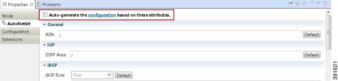
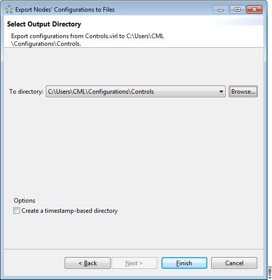
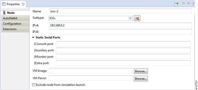
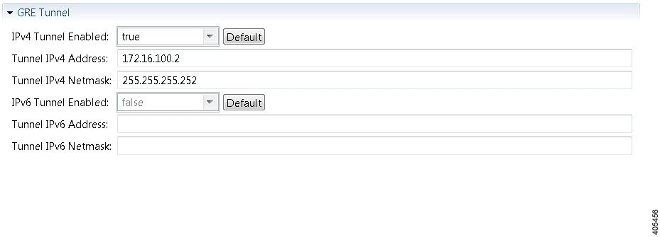
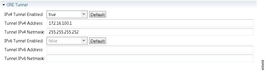
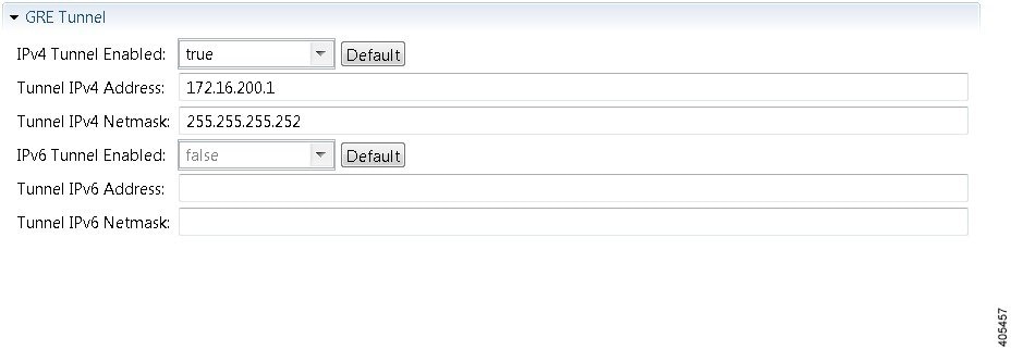
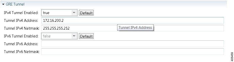
In the build phase, you build the configurations for each node. After selecting the options for the overall topology and each node, you create the configuration files. Alternatively, you can use AutoNetkit to create the configuration files.

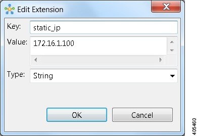
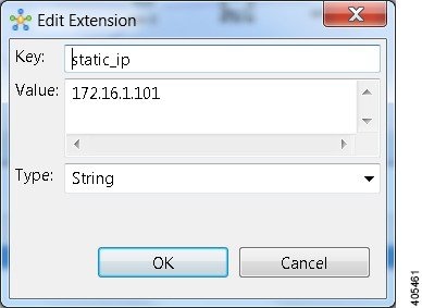
You can modify and save configuration files for the topology and for each node in your topology.

Create and Modify a Node Configuration

While AutoNetkit is useful for generating configuration files for all the nodes in the topology, you can bypass AutoNetkit and enter node configuration information directly.

You can enter configuration information in either of the following ways:

  • During the design phase, copy and paste configuration commands for each node.

  • During the simulation phase, connect to a node console and change its configuration when the topology is running. See the chapter Simulate the Topology for more information on how to modify, extract, and save a running configuration.


Note

When you create your configuration files:
  • Changes that are manually entered are not visible in the topology design. If you create a new interface by entering configuration commands, the interface is not created in OpenStack nor does the interface show up in any of the node views.
  • Depending on how the AutoNetkit Auto-generate the configuration based on these attributes feature is set, you may overwrite the changes you enter.

While in the Design perspective, any changes you manually make to a node configuration are saved in the current filename .virl file. Before you launch a simulation from the Design perspective, a notification window advises you to save the changes or cancel the simulation launch.

Figure 1. Save Changes Before Launch


Create a Node Configuration Manually

Before you begin

The topology design should be complete.

Procedure


Step 1

In the Topology Editor, click a node.

Step 2

In the Properties view, click AutoNetkit and uncheck the Auto-generate the configuration based on these attributes check box.

Figure 2. Uncheck Auto-generate Check Box


Step 3

Click the Configuration tab.

Step 4

Enter the configuration commands in the Configuration view.

Note 
All changes are automatically saved to the filename .virl file. However, the changes made do not appear in the topology on the canvas.

Use an Existing Node Configuration

You can use an existing configuration file to create a node configuration in Cisco Modeling Labs.

Before you begin

The topology design should be complete.

Procedure


Step 1

In the Topology Editor, click a node.

Step 2

In the Properties view, click AutoNetkit and uncheck the Auto-generate the configuration based on these attributes check box.

Step 3

Click the Configuration tab.

  1. Open the configuration file you want to use and copy the configuration commands.

  2. In the Configuration view, paste the configuration commands.

    Note 
    All changes are automatically saved to the filename.virl file. However, the changes made do not appear in the topology on the canvas.

What to do next

Launch a simulation to observe the changes.

Import the Configuration from Other Types of Files

For this version of Cisco Modeling Labs, you are able to import configurations from a number of other file types, such as, Cariden MATE, Visio, GNS3 to name a few. These are discussed in the following sections.

Import the Configuration from a Cariden MATE File

You can import a topology from an existing Cariden MATE file, version 5.2.0 or later or version 6.1.0. Cisco Modeling Labs client will accept site imports up to two layers deep. Any Cariden MATE file that has a topology with more than two layers of sites will not import correctly.

Procedure


Step 1

Choose File > Import.

A window appears, prompting you to Import Cariden MATE file.
Step 2

Choose Import Cariden MATE File then click Next.

Step 3

Choose the From data file Cariden MATE file to import. Use Browse to select the directory and file to import.

Step 4

Choose the location Into target folder for the Cariden MATE file. Use Browse to select the target Project folder.

Figure 3. Choose the From and To Locations


Step 5

Enter a filename for the imported Cariden MATE file.

Important 
The filename you enter must have the extension .virl. For example, Lab_import.virl is a valid filename. Otherwise, you cannot open the file in the topology editor.
The Cariden MATE file converts to a Cisco Modeling Labs .virl file.
Step 6

In the Projects view, expand the project folder where you saved the imported file.

Step 7

Right click on the imported file, for example, Lab_import.virl and choose Open With > Topology Editor.

The canvas opens and displays the topology.
Figure 4. Imported Cariden MATE File


Export the Configuration to Cariden MATE File

Procedure

Step 1

Choose File > Export.

A window appears, prompting you to Export to Cariden MATE file.
Step 2

Choose Export Cariden MATE File then click Next.

Step 3

Choose the location To file for the Cariden MATE file export. Use Browse to select the target Project folder.

Step 4

Enter a filename for the exported Cariden MATE file, or use the default filename. For example, sample_topology.virl is converted to sample_topology.pln and saved in the target directory.

Step 5

Click Finish.

The Cisco Modeling Labs .virl file silently converts to a Cariden MATE .pln file.

Import the Configuration from a Visio vsdx File

You can import a topology from an existing Visio .vsdx file, version 2013 and later.

Procedure


Step 1

Choose File > Import.

The Import dialog box appears.
Step 2

Expand the Topology folder, choose Import Visio vsdx File and click Next.

Step 3

Choose the From data file Visio .vsdx file to import. Use Browse to select the directory and file to import.

Step 4

Choose the location Into target folder for the Visio .vsdx file. Use Browse to select the target Project folder.

Figure 5. Choose the From and To Locations


Step 5

Click Finish.

The Visio .vsdx file converts to a Cisco Modeling Labs .virl file, using the original filename of the file and it is automatically opened on the canvas.

Export the Configuration to SVG Files

For this release of Cisco Modeling Labs, export to Visio .vsdx files is not supported. However, export to .svg files is supported, as Visio supports the use of .svg files. The Export option can be used to export .virl files as .svg files.

Procedure

Step 1

Choose File > Export.

A window appears, prompting you to Export to SVG file.
Step 2

Choose Export to SVG file then click Next.

Step 3

Choose the location To file for the SVG file export. Use Browse to select the target Project folder.

Step 4

Enter a filename for the exported SVG file, or use the default filename. For example, sample_topology.virl is converted to sample_topology.svg and saved in the target directory.

Step 5

Click Finish.

The Cisco Modeling Labs .virl file silently converts to a SVG .svg file.

Import the Configuration from a GNS3 File

You can import a topology from an existing GNS3 .gns3 file.

Before you begin

  • A valid GNS3 JSON-based (.gns3) file is available on your file system.

  • Cisco Modeling Labs client is running.

Procedure


Step 1

Choose File > Import.

The Import dialog box appears.
Step 2

Expand the Topology folder, choose Import GNS3 File and click Next.

Figure 6. Import a GNS3 .gns3 File


The Import GNS3 File dialog box is displayed.
Step 3

In the From source file field, use Browse to select the directory and GNS3 .gns3 file to import.

Step 4

In the Into destination file field, use Browse to select the target folder.

Figure 7. Choose the From and To Locations


Step 5

Click Finish.

The GNS3 .gns3 file converts to a Cisco Modeling Labs .virl file, using the original filename of the file and it is automatically opened on the canvas.

Export the Configuration to GNS3 Files

Before you begin
  • Cisco Modeling Labs client is running.

  • A topology is open in the Topology Editor.

Procedure

Step 1

Choose File > Export.

The Export dialog box appears.
Step 2

Expand the Topology folder, choose Export to GNS3 File and click Next.

Figure 8. Export a GNS3 .gns3 File


Step 3

In the To file field, use Browse to select the target folder.

Figure 9. Export a GNS3 .gs3 File


Step 4

Enter a filename for the exported GNS3 file, or use the default filename. For example, sample_topology.virl is converted to sample_topology.gns3 and saved in the target directory.

Step 5

Click Finish.

The Cisco Modeling Labs .virl file silently converts to a GNS3 .gns3 file.

Import the Configuration from a GraphML File

You can import a topology from an existing GraphML .graphml file.

Before you begin

  • A valid GraphML file is available on your file system.

  • Cisco Modeling Labs client is running.

Procedure


Step 1

Choose File > Import.

The Import dialog box appears.
Step 2

Expand the Topology folder, choose Import GraphML and click Next.

Figure 10. Import a GraphML .graphml File


The Import GraphML File dialog box is displayed.
Step 3

In the From source file field, use Browse to select the directory and GraphML .graphml file to import.

Step 4

In the Into destination file field, use Browse to select the target folder.

Figure 11. Choose the From and To Locations


Step 5

Click Finish.

The GraphML .graphml file converts to a Cisco Modeling Labs .virl file, using the original filename of the file and it is automatically opened on the canvas.

Export the Configuration to GraphML Files

Before you begin
  • Cisco Modeling Labs client is running.

  • A topology is open in the Topology Editor.

Procedure

Step 1

Choose File > Export.

The Export dialog box appears.
Step 2

Expand the Topology folder, choose Export to GraphML File and click Next.

Figure 12. Export a GraphML .graphml File


Step 3

In the To file field, use Browse to select the target folder.

Figure 13. Choose the To Location


Step 4

Enter a filename for the exported GraphML file, or use the default filename. For example, sample_topology.virl is converted to sample_topology.graphml and saved in the target directory.

Step 5

Click Finish.

The Cisco Modeling Labs .virl file silently converts to a GraphML .graphml file.

Import the Nodes Configuration Files

You can import the per-node configurations previously exported as individual text files (.cfg suffix) into your .virl file. You can import the configuration files having made any necessary changes to them.

Before you begin

  • Cisco Modeling Labs client is running.

  • A topology file is open in the Topology Editor.

Procedure


Step 1

Choose File > Import.

The Import dialog box is displayed.
Figure 14. Import Dialog Box


Step 2

Choose Import Configurations into Existing Topology and click Next.

The Import Configurations into Existing Topology dialog box is displayed.
Figure 15. Import Configurations into Existing Topology


Step 3

Select the applicable location from the From Directory drop-down list or choose Browse.

Step 4

Click Finish to import the node configuration files.

The node configuration files are imported into the existing topology and a message is displayed to confirm this
Figure 16. Config Import Finished Dialog Box


.

Export the Nodes Configuration Files

You can export the per-node configurations from within your .virl file and export them to a directory location of your choice as individual text files (.cfg suffix). There you can make necessary changes to the configuration files before importing the configuration files back into the .virl file.

Before you begin

  • Cisco Modeling Labs client is running.

  • A topology file is open in the Topology Editor.

Procedure


Step 1

Choose File > Export.

The Export dialog box is displayed.
Figure 17. Export Dialog Box


Step 2

Choose Export Nodes' Configurations to Files and click Next.

The Export Nodes' Configurations to Files dialog box is displayed.
Figure 18. Export Nodes' Configurations to Files


Step 3

Select a location from the To Directory drop-down list or choose Browse to select the applicable location.

Step 4

Click Finish to export the node configuration files.

The node configuration files are exported to the chosen location.

Create Node and Interface Configurations Using AutoNetkit

Before you begin

The topology design should be complete.

Procedure


Step 1

AutoNetkit displays a notification after it generates the configuration. Click No to skip a comparison of configuration changes. Click Yes to open a comparison view of the configuration changes.

Figure 19. View Configuration Changes? Notification


The .virl file opens and displays previous and current configurations side-by-side, with the changes highlighted. You can scroll through the contents and see the differences. However, you cannot edit the configurations.
Figure 20. Show Configuration Comparison Side-by-Side


Click OK to close the comparison view.
Step 2

When you close the comparison view, a notification is displayed, and you can choose whether or not to open AutoNetkit Visualization.

  • Click No to skip the visualization. You return to the Design perspective.

  • Click Yes to display the visualization. The AutoNetkit Visualization opens in a browser window. For more information about this feature, see AutoNetkit Visualization.

Figure 21. Open AutoNetkit Visualization? Notification


Note 
Selecting the Remember my decision check box will always open AutoNetkit visualization for subsequent invocations. You can later change this behavior by choosing File > Preferences > Web Services > AutoNetkit.

Generate an Infrastructure-only Configuration Using AutoNetkit

AutoNetkit allows you to generate a stripped-back configuration that provides the basic infrastructure configuration required to support configuration extraction and Live Visualization.

With this feature enabled, no IP addressing or routing protocol configuration is created. This leaves the node in a state where it is ready for manual configuration. This is ideal when using a simulation for study practice or when wanting to go through the process of building an environment by hand.

The feature is enabled in the Cisco Modeling Labs client, by selecting the Infrastructure Only option available under General at the topology level under the AutoNetkit tab, as shown.

Static TCP Port Allocation Control

You can specify the TCP port number that you want to use when connecting to the console, auxiliary, or monitor ports of a particular node running in a simulation. These port numbers are optional and can be set via the Cisco Modeling Labs client. The port number allocation is retained in the settings.ini file and is applied each time the simulation is started. Functionality is provided so that the TCP port numbers in use are easily adjusted.

To set these port numbers, in the Design perspective, select a node and choose the Node configuration tab. Update the Static Serial Ports' fields as required.
Figure 22. Specify TCP Port Numbers


Assign VLANs

VLANs can be assigned to the interfaces of the end nodes, using the Properties > Interface view.

These VLAN values are displayed in the VLAN attribute of the interfaces in AutoNetkit visualization:
Figure 23. VLAN Property Assigned


Use a Managed Switch

The Cisco IOSv Layer 2 switch introduces a managed switch to the Cisco Modeling Labs environment.

By default, all VLANs are placed in vlan2.

For example, consider the following topology which includes four nodes and one Cisco IOSvL2 image:

After running AutoNetkit, you can see the default VLAN assigned using the vtp view:
Figure 24. VLAN Assignment


The layer2 view shows the vtp domain originating from the virtual switch for vlan2:
Figure 25. Vtp Domain - layer2.tiff


The resultant interface configurations for the Cisco IOSvL2 image are reflected as follows::
interface GigabitEthernet0/1
 description to iosv-1
 switchport access vlan 2
 switchport mode access
 no shutdown
!
interface GigabitEthernet0/2
 description to iosv-3
 switchport access vlan 2
 switchport mode access
 no shutdown
!
interface GigabitEthernet0/3
 description to iosv-2
 switchport access vlan 2
 switchport mode access
 no shutdown
!
interface GigabitEthernet1/0
 description to iosv-4
 switchport access vlan 2
 switchport mode access
 no shutdown
!

Use Multiple Managed Switches

It is permissible to connect multiple managed switches together. Multiple managed switches connected together form a trunk link between the switches and their appropriate vtp domains.

In the following example, two managed switches are connected together:

The vtp view shows the trunk link created between the two managed switches:
Figure 26. Trunk Link Created


The layer2 view shows the resulting layer2 connectivity, where both of the managed switches have been aggregated into a single vtp domain for the default vlan2:
Figure 27. Layer2 Connectivity


The resultant interface configurations for iosvl2-1 and iosvl2-2 are as follows:

iosvl2-1
interface GigabitEthernet0/1
 description to iosv-1
 switchport access vlan 2
 switchport mode access
 no shutdown
!
interface GigabitEthernet0/2
 description to iosv-3
 switchport access vlan 2
 switchport mode access
 no shutdown
!
interface GigabitEthernet0/3
 description to iosv-2
 switchport access vlan 2
 switchport mode access
 no shutdown
!
interface GigabitEthernet1/0
 description to iosv-4
 switchport access vlan 2
 switchport mode access
 no shutdown
!
interface GigabitEthernet1/1
 description to iosvl2-2
 switchport trunk encapsulation dot1q
 switchport mode trunk
 no shutdown
!
iosvl2-2
interface GigabitEthernet0/1
 description to iosvl2-1
 switchport trunk encapsulation dot1q
 switchport mode trunk
 no shutdown
!
interface GigabitEthernet0/2
 description to server-1
 switchport access vlan 2
 switchport mode access
 no shutdown
!
interface GigabitEthernet0/3
 description to iosv-5
 switchport access vlan 2
 switchport mode access
 no shutdown
!

Set Firewall Capabilities

This release of Cisco Modeling Labs includes the demo version of the Cisco ASAv image (a fully-operational license is available by separate purchase). The Cisco ASAv image adds firewall capabilities to Cisco Modeling Labs.

The default AutoNetkit configuration puts each interface into security-level 0, adds a nameif, and allows http, SSH, and Telnet access to this nameif.

For example, consider the following topology which includes three IOSv nodes, one server node and one ASAv node:

After running AutoNetkit, the firewall view shows the allocated properties on the interfaces:
Figure 28. Allocated Firewall Properties


The configuration for the interface is:
interface GigabitEthernet0/0
 description to server-1
 nameif outside
 security-level 0
 no shutdown
 ip address 10.0.0.5 255.255.255.252
interface GigabitEthernet0/1
 description to iosv-1
 nameif outside-1
 security-level 0
 no shutdown
 ip address 10.0.0.9 255.255.255.252
interface GigabitEthernet0/2
 description to iosv-2
 nameif outside-2
 security-level 0
 no shutdown
 ip address 10.0.0.13 255.255.255.252
interface GigabitEthernet0/3
 description to iosv-3
 nameif outside-3
 security-level 0
 no shutdown
 ip address 10.0.0.17 255.255.255.252
The access details are:
http 0.0.0.0 0.0.0.0 mgmt
ssh 0.0.0.0 0.0.0.0 mgmt
telnet 0.0.0.0 0.0.0.0 mgmt
http 0.0.0.0 0.0.0.0 outside
ssh 0.0.0.0 0.0.0.0 outside
telnet 0.0.0.0 0.0.0.0 outside
http 0.0.0.0 0.0.0.0 outside-1
ssh 0.0.0.0 0.0.0.0 outside-1
telnet 0.0.0.0 0.0.0.0 outside-1
http 0.0.0.0 0.0.0.0 outside-2
ssh 0.0.0.0 0.0.0.0 outside-2
telnet 0.0.0.0 0.0.0.0 outside-2
http 0.0.0.0 0.0.0.0 outside-3
ssh 0.0.0.0 0.0.0.0 outside-3
telnet 0.0.0.0 0.0.0.0 outside-3

Set Security Levels

The security level is displayed in the security_level attribute of the interfaces in AutoNetkit visualization:
Figure 29. Security Level Attribute Set


The configuration for nameif is updated.
interface GigabitEthernet0/0
 description to server-1
 nameif level-50
 security-level 50
 no shutdown
 ip address 10.0.0.5 255.255.255.252
interface GigabitEthernet0/1
 description to iosv-1
 nameif outside
 security-level 0
 no shutdown
 ip address 10.0.0.9 255.255.255.252
interface GigabitEthernet0/2
 description to iosv-2
 nameif outside-1
 security-level 0
 no shutdown
 ip address 10.0.0.13 255.255.255.252
interface GigabitEthernet0/3
 description to iosv-3
 nameif outside-2
 security-level 0
 no shutdown
 ip address 10.0.0.17 255.255.255.252

The access details are also updated.
http 0.0.0.0 0.0.0.0 level-50
ssh 0.0.0.0 0.0.0.0 level-50
telnet 0.0.0.0 0.0.0.0 level-50
http 0.0.0.0 0.0.0.0 mgmt
ssh 0.0.0.0 0.0.0.0 mgmt
telnet 0.0.0.0 0.0.0.0 mgmt
http 0.0.0.0 0.0.0.0 outside
ssh 0.0.0.0 0.0.0.0 outside
telnet 0.0.0.0 0.0.0.0 outside
http 0.0.0.0 0.0.0.0 outside-1
ssh 0.0.0.0 0.0.0.0 outside-1
telnet 0.0.0.0 0.0.0.0 outside-1
http 0.0.0.0 0.0.0.0 outside-2
ssh 0.0.0.0 0.0.0.0 outside-2
telnet 0.0.0.0 0.0.0.0 outside-2


Note

AutoNetkit automatically renames the nameif if there are multiple interfaces with the same security level.

Configure GRE Tunnels

Generic routing encapsulation (GRE) is a simple IP packet encapsulation protocol that is used to transport packets over a network. Information is sent from one network to the other through a GRE tunnel.

The GRE tunnel functionality uses the IOSv subtype as the GRE tunnel head and connects from an IOSv instance out over the FLAT/FLAT1/SNAT connector to some other device which is the far-end of the GRE Tunnel.

In this example, you set the values on node iosv-1 and node iosv-2 to tell AutoNetkit to create the configuration for a GRE tunnel terminating on the external router node, ext_router_1.

So on iosv-1, set the tunnel IP address and subnet mask of the far-end device ext-router-1. Similarly, on the ext-router-1, set the tunnel IP address and subnet mask of the far-end device iosv-1.
Figure 30. Tunnel IP Address and Subnet Mask for ext_router_1


Figure 31. Tunnel IP Address and Subnet Mask for iosv-1


On iosv-2, set the tunnel IP address and subnet mask of the far-end device ext-router-2. Similarly, on the ext-router-2, set the tunnel IP address and subnet mask of the far-end device iosv-2.
Figure 32. Tunnel IP Address and Subnet Mask for ext_router_2


Figure 33. Tunnel IP Address and Subnet Mask for iosv-2


When the configurations are built, AutoNetkit selects the appropriate corresponding IP address and applies it to the interface as follows:
!
interface Tunnel1
  ip address 172.16.100.2 255.255.255.252
  tunnel source GigabitEthernet0/3
  tunnel destination 0.0.0.0
!
The tunnel destination is blank since it needs to be set to the IP address of the far-end device, which you may or may not know in advance. However, you can edit the configuration in the Cisco Modeling Labs client GUI before you start up the simulation. So if you do know the target address, you can add the target IP address in there (tunnel destination x.x.x.x.) Remember that it is not the IP address of the tunnel that goes in here but the IP address of the router/device terminating the GRE tunnel itself. If this is a devices that is on the FLAT network directly, then a 172.16.1.x address would go in here.
To make things simple and repeatable, you can use a static IP address on the interface of the IOSv GRE tunnel device that connects to the FLAT/FLAT1/SNAT connector.
Figure 34. Static IP Address for flat-1


Figure 35. Static IP Address for flat-2


This provides a target address that the other device can then try to connect to and it is the same IP address each time the simulation is started.

Note

You cannot do this using the standard guest account. The simulation will fail as you are using a system-level resource (the Static IP address), so an account with administrative permissions is required.
You must create this account in the User Workspace Management interface.
In the User Workspace Management interface, under the Projects tab, click Add to create a new project, as follows:
Figure 36. Create a New Project


In the corresponding user created for the project, set Role to admin.
Figure 37. Update the Role Field


In the Cisco Modeling Labs client GUI, choose File > Preferences > Web Services.. In the Web Services dialog box, click Change under Master Credentials to login with the newly created user.
Figure 38. Log In as New Role


You can now start your simulation.

Automatic Configuration for OpenDayLight Controllers

Cisco IOS XRv virtual machines, version 5.3.0 and upwards can be automatically configured for communication and operation with an OpenDayLight (ODL) controller for path manipulation and control using MPLS TE tunnels. An option in available under the AutoNetkit properties tab in the Cisco Modeling Labs client called ODL Management Group. Cisco IOS XRv devices set with the ODL management group attribute must be paired with an external router entity, which is configured with the matching ODL Management Group attribute and an ODL external server IP address. The ODL server may be running on your Cisco Modeling Labs server or another location. It does not need to be part of the Cisco Modeling Labs simulation itself. However, connectivity between the simulation and the server must be provided.