User Workspace
Management
Access the User Workspace Management Interface
After you have started the Cisco Modeling Labs server, you can access the User Workspace Management interface to manage user accounts, projects, licenses, and virtual machine images on the Cisco Modeling Labs server.
To access the User Workspace Management interface, complete the following steps:
User Management Workspace User Types
Within the User Management Workspace interface there are two types of users available. These are administrator and non-administrator user. The following tables describe the different functions available for each user type.
|
Function |
Description |
|---|---|
|
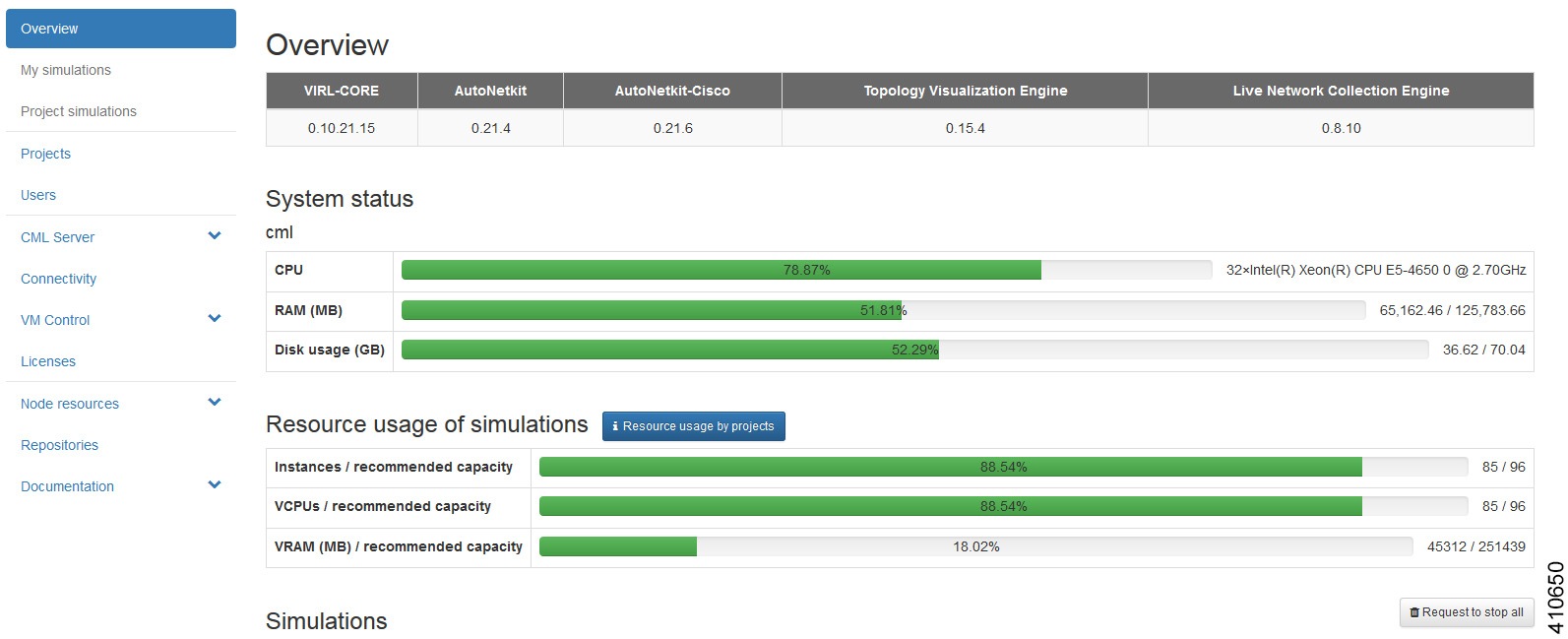
Overview |
Allows you to view current system version information, physical resource usage, and a list of all deployed simulations. You can stop all or selected simulations. |
|
Projects |
Allows you to import and export projects. You can also add new projects, enable, disable, modify, and delete current projects. |
|
Users |
Allows you add new users, enable, disable, modify, and delete current users. |
|
CML Server |
Under System Configuration, you can set configuration parameters. Under System Status, you can collect, view and download system status information. |
|
Connectivity |
Allows you to add and delete L2 Flat IP, L3 Snat IP, and Management IP allocations for projects. |
|
VM Control |
Allows you to delete nodes, networks, ports and IP allocations, as well as disable some host services when problems are encountered. |
|
Licenses |
Allows you to manage product licenses on the system. |
|
Node Resources |
Allows you add new images, modify, and delete current images. You can also modify and delete image snapshots. You can add and delete flavors and import and export subtypes. You can also create a new subtype based on one of the available built in subtypes. You can manage and add new LXC images and templates. |
|
Repositories |
Allows you to add, delete, and refresh files from Git repositories. |
|
Documentation |
Allows you to access STD and UWM API documentation. |
|
Function |
Description |
|---|---|
|
My Simulations |
Review and operate a user's own simulations. |
|
Project Simulations |
Review simulations in a user's own project. |
|
Connectivity |
Review a user's own IP address allocations. |
|
Node Resources |
Review details for flavors and subtypes. Review and add new images, LXC images and templates for use by the user's own project. |
|
Repositories |
Allows you to add, delete, and refresh files from Git repositories. |
|
Documentation |
Allows you to access STD and UWM API documentation. |
Projects (Admin User)
Within the User Workspace Management interface, a project represents a set of resources that are available to all users of that project. It has the following characteristics:
- By default, each project is created with one user account that has the same name as the project.
- Each user belongs to exactly one project. Users should typically each have a project of their own, hence creating a new project is the preferred and efficient process for adding new users.
- Additional users can be assigned to a project as required.
- If a user is added to a project, the username of the user is prefixed with the project name.
- Deleting a user account does not delete a project that the user is assigned to.
- Deleting a project deletes all users of the project.
|
Operation |
Description |
|---|---|
|
Import |
Imports a project and its users from a JavaScript Object Notation (JSON) or tab-Separated values (TSV) file. |
|
Export |
Exports a project and its users as a JSON or TSV file. |
|
Add |
Creates a new project and its default user. |
|
Enable |
Enables a selected project. |
|
Disable |
Disables a selected project. |
|
Modify |
Modifies details for a selected project. |
|
Delete |
Deletes a selected project and its users. |
Create a Project
To create a new project, and a user for the project complete the following steps:
| Step 1 | In the
User Workspace
Management interface, click
Projects.
The Projects page, which lists all of the current projects, appears. | ||
| Step 2 | Click
Add to
create a new project.
The
Create
Project page appears.
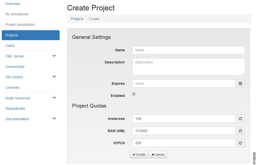 | ||
| Step 3 | Under General Settings, add a name and a description for the project. In the Expires field, you can either add an expiry date for the project or accept the default, which is Never, meaning the project will never expire. Leave the Enabled check box checked to enable the project for use. | ||
| Step 4 | Under
Project
Quotas, you can either accept the default values for the system quotas or
increase or decrease them based on your project requirements:
| ||
| Step 5 | Click
Create.
The Edit User page appears. 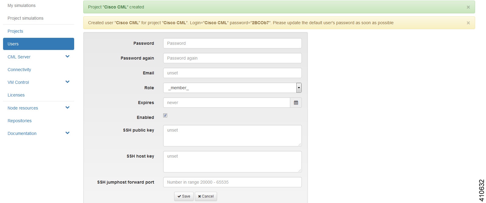
Using this window, you can add details for the new user created when the project is created. | ||
| Step 6 | In the
Password and
Password
Again fields, enter a new password for the user.
| ||
| Step 7 | In the Email field, add a valid email address for the user. By default, the user is assigned a member role, which means the user is a non-admin account. Set Role to admin if the user needs to perform the same administrative functions as the uwmadmin user. | ||
| Step 8 | In the Expires field, you can add an expiry date for the user or accept the default Never. Leave the Enabled check box checked to enable the project for immediate use. Alternatively, you can set up a project and users, but you cannot enable them to be configured and available at a later time. | ||
| Step 9 | Click Save to save the changes for the user. | ||
| Step 10 | (Optional) To confirm that the project has been added, click Projects to view the newly added project, and click Users to view the newly added user. |
Export a Project
Export allows you to export selected projects and all their users to a JSON or TSV file.
To export a project and all its users, complete the following steps:
| Step 1 | In the User Workspace Management interface, click Projects. The Projects page, which lists all of the current projects, appears. |
| Step 2 | Check the check box beside the project or projects for export. |
| Step 3 | Click
Export to
export the selected projects and all their users.
|
| Step 4 | From the drop-down list, choose the type of file to export to, JSON or TSV. The Open dialog box appears. |
| Step 5 | Click the Save File radio button and click OK to save the file. The exported file is saved to the specified location. |
Import a Project
 Note | The uwmadmin project and user are not modified by this function when imported data contains it. |
To import a project and its users, complete the following steps:
| Step 1 | In the User Workspace Management interface, click Projects. The Projects page, which lists all of the current projects, appears. | ||
| Step 2 | Click
Import to
import a new project and its associated users.
The Import Projects and Users page appears. | ||
| Step 3 | Click
Browse to
locate the applicable JSON or TSV file for import.
| ||
| Step 4 | Click Import. The newly imported project is listed on the Projects page. |
Users (Admin User)
Within the User Workspace Management interface, you can manage user accounts from the Users page. User accounts permit access to the Cisco Modeling Cisco Modeling Labs server from the Cisco Modeling Labs client.
|
Operation |
Description |
|---|---|
|
Add |
Creates a new user account. |
|
Enable |
Enables a selected user account. |
|
Disable |
Disables a selected user account. |
|
Modify |
Modifies details for a selected user account. |
|
Delete |
Deletes a selected user account. |
Create a User
Note | It is preferred for each user to have their own project. |
| Step 1 | In the User Workspace Management interface, log in as admin and click Users. The Users page, which lists all the users, appears. | ||
| Step 2 | Click
Add to
create a new user.
The Create User page appears. 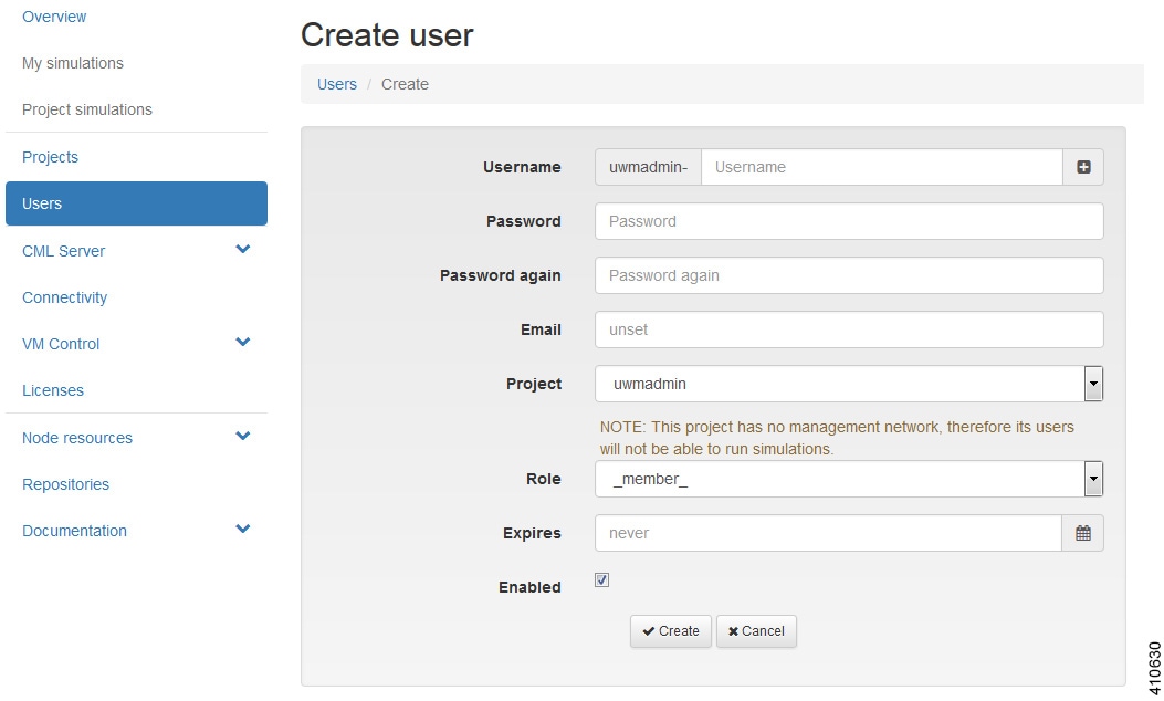 | ||
| Step 3 | In the
Username
field, enter a username for the new user.
| ||
| Step 4 | In the Password and Password Again fields, enter a password for the new user. | ||
| Step 5 | In the Email field, enter a valid email address for the user. | ||
| Step 6 | From the Project drop-down list, choose the applicable project for the user. | ||
| Step 7 | From the
Role
drop-down list, choose the applicable role for the user.
| ||
| Step 8 | In the Expires field, you can either add an expiry date for the user or accept the default, which is Never. | ||
| Step 9 | Leave the Enabled check box checked. | ||
| Step 10 | Click
Create.
The User <Project Name>-<Username> page appears. This page presents details and project quotas for the user. | ||
| Step 11 | (Optional) Click Modify User to amend the details for a user, or click Delete User to delete the user. | ||
| Step 12 | Click Users to view the newly created user. |
Change an Account Password
You can at anytime change the password for a user account, admin or non-admin. To change a password, complete the following steps:
| Step 1 | Login in to the User Workspace Management interface. |
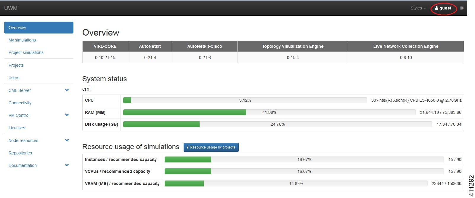
| Step 2 | At the top right
of the page, click the
User icon to access the User Settings page, as shown in red.
 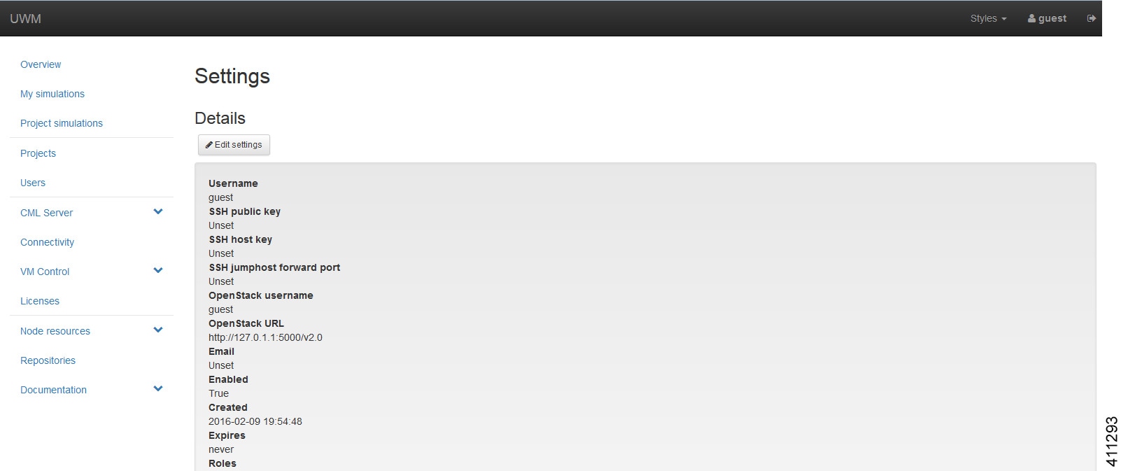 |
| Step 3 | Click
Edit
Settings.
The
Edit
Settings page is displayed.
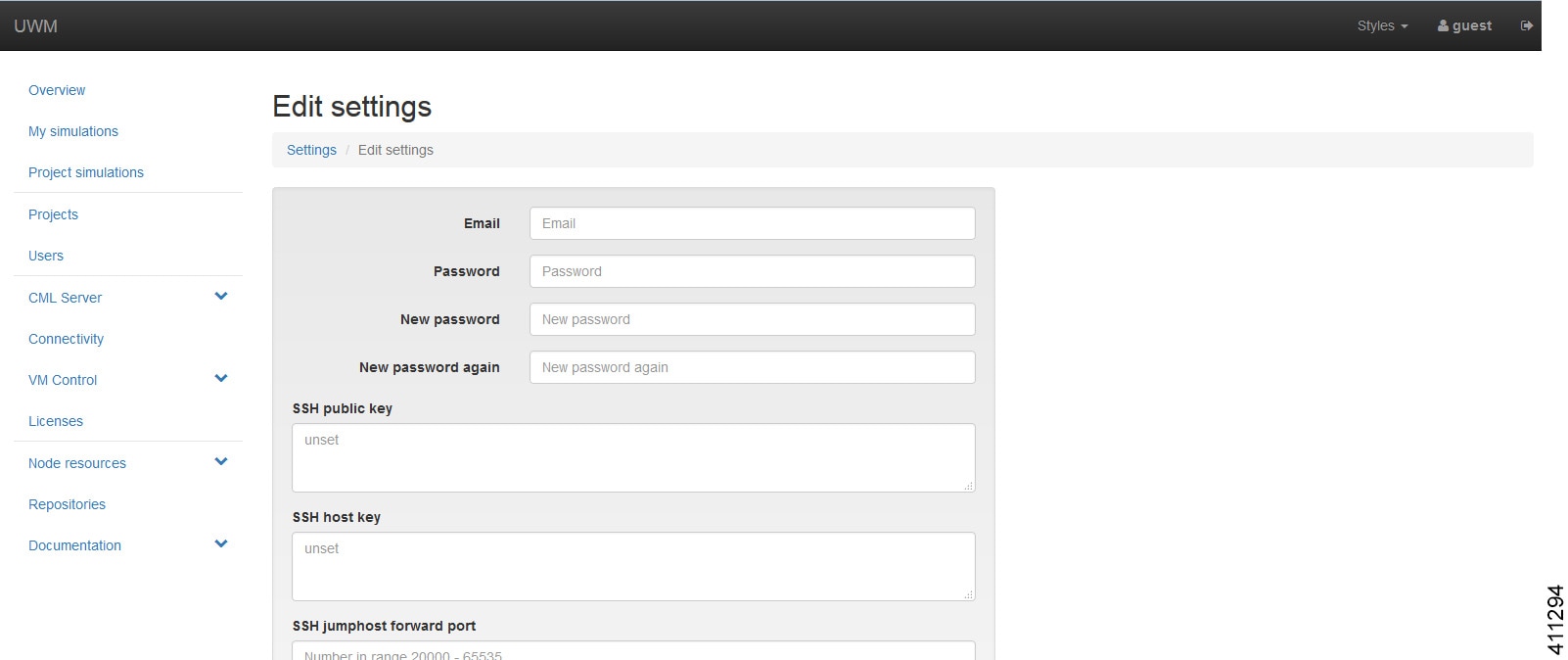 |
| Step 4 | Enter new password details and click Confirm to save the changes. |
CML Server (Admin User)
Within the User Workspace Management interface, under CML Server, you are able to make changes to your Cisco Modeling Labs server configuration under the System Configuration option.
Under the System Status option, you can review system operational statuses and download log files.
System Configuration
Within the User Workspace Management interface, under CML Server, you are able to make changes to your Cisco Modeling Labs server configuration.
System Configuration Controls
To update system configuration controls, complete the following steps:
| Step 1 | In the
User Workspace
Management interface, click
.
The System Configuration Controls page appears. 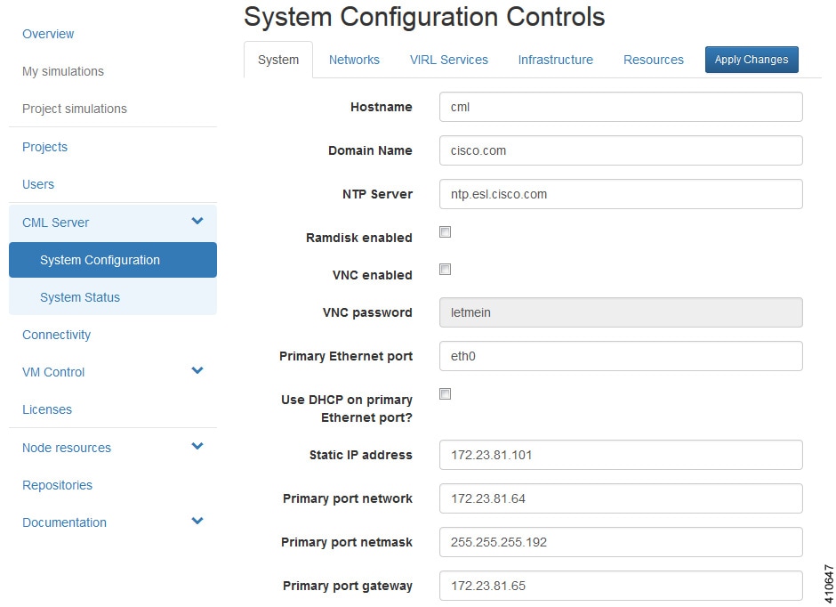
| ||||||||||||||||||||||||||||||||||
| Step 2 | Update the
fields as required.
| ||||||||||||||||||||||||||||||||||
| Step 3 | Click Apply Changes when you are finished to save your changes. |
Networks Configuration
To update the Networks configuration, complete the following steps:
| Step 1 | In the
User Workspace
Management interface, click
.
The System Configuration Controls page appears. Click the Networks tab to access the network parameters. 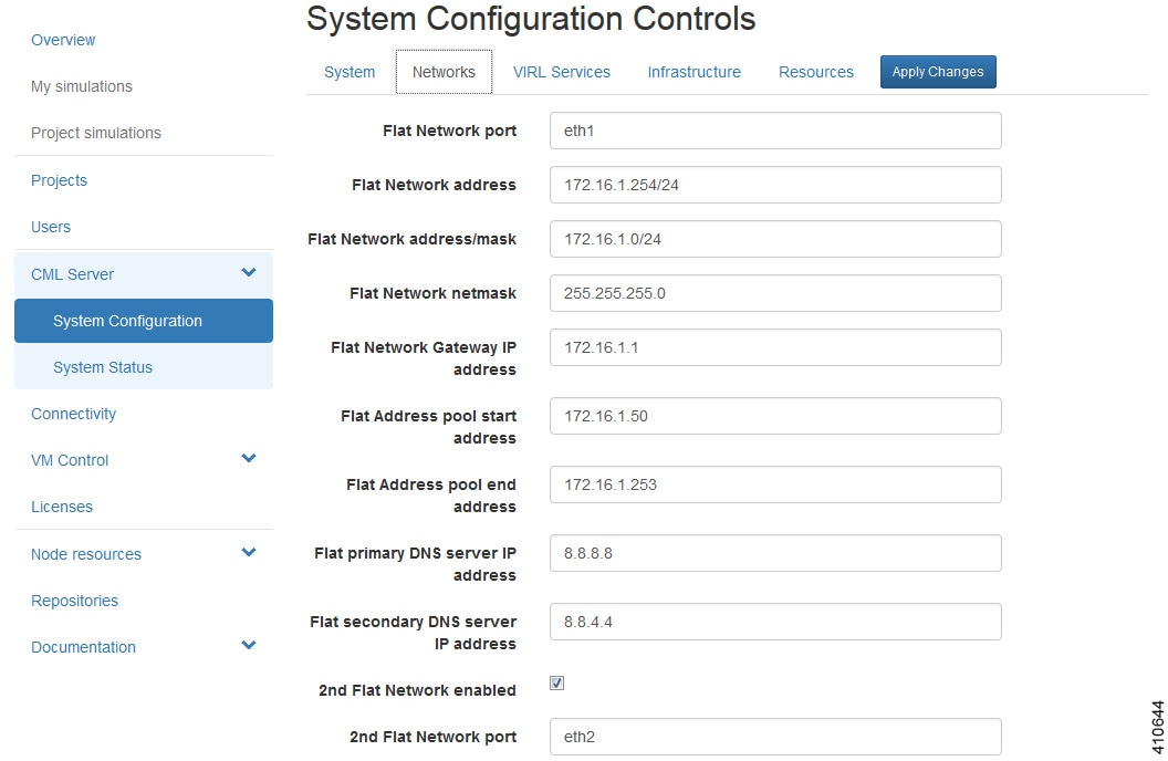
| ||||||||||||||||||||||||||||||||||||||||||||||||||||||||||
| Step 2 | Update the
fields as required.
| ||||||||||||||||||||||||||||||||||||||||||||||||||||||||||
| Step 3 | Click Apply Changes when you are finished to save your changes. |
VIRL Services Configuration
To update the VIRL services configuration, complete the following steps:
| Step 1 | In the
User Workspace
Management interface, click
.
The System Configuration Controls page appears. Click the VIRL Services tab to access the VIRL services parameters. 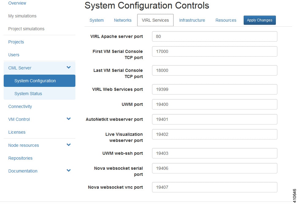
| ||||||||||||||||||||||
| Step 2 | Update the
fields as required.
| ||||||||||||||||||||||
| Step 3 | Click Apply Changes when you are finished to save your changes. |
Infrastructure Configuration
To update the Infrastructure configuration, complete the following steps:
| Step 1 | In the
User Workspace
Management interface, click
.
The System Configuration Controls page appears. Click the Infrastructure tab to access the infrastructure parameters. 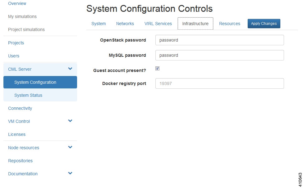
| ||||||||||
| Step 2 | Update the
fields as required.
| ||||||||||
| Step 3 | Click Apply Changes when you are finished to save your changes. |
Resources Configuration
To update the Resources configuration, complete the following steps:
| Step 1 | In the
User Workspace
Management interface, click
.
The System Configuration Controls page appears. Click the Resources tab to access the resources parameters. 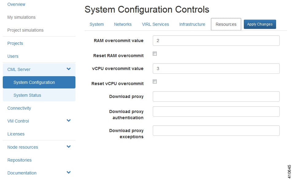
| ||||||||||||||||
| Step 2 | Update the
fields as required.
| ||||||||||||||||
| Step 3 | Click Apply Changes when you are finished to save your changes. |
System Status
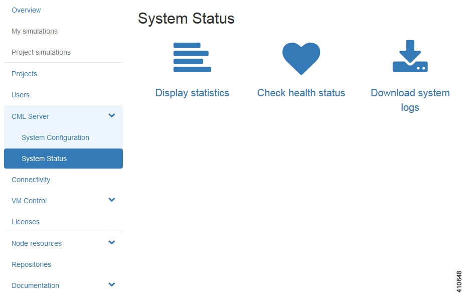
To download the system log files, click Download System Logs. A dialog box is displayed where you can opt to open or save the system log file.
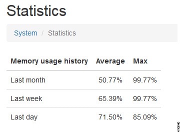
System Statistics
You can view various statistics concerning the usage and operation of your Cisco Modeling Labs system. System statistics are available from the User Workspace Management interface under .
The following areas are covered:
|
Area |
Description |
|---|---|
|
Statistics |
 |
|
Projects and Users |
Lists the number of current projects and users. 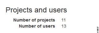 |
|
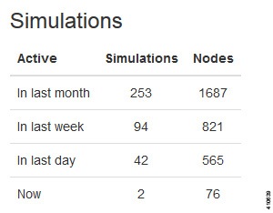
Simulations |
 |
|
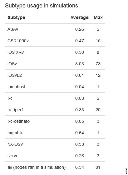
Subtype Usage in Simulations |
 |
|
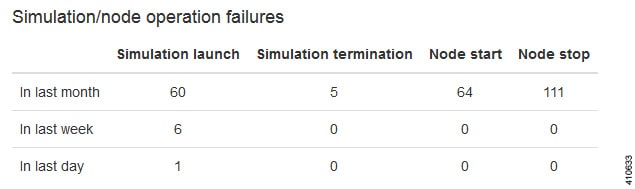
Simulation/node Operation Failures |
 |
|
AutoNetkit |
Lists details for the number of configurations generated in the last week, the last month, and the previous 24 hours, including the number of invalid topologies encountered. The category Subtype Usage in Configured Topologies lists the subtypes used in configuration requests along with their average and maximum usage stats. 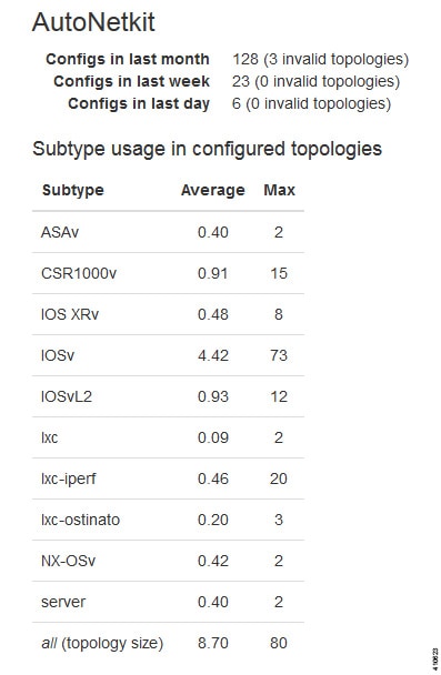 |
System Health Status
You can check on server status and system services that are running using the Check Health Status option. It performs a system check and generates a report. It is available from the User Workspace Management interface under .
|
Area |
Services Checked |
|---|---|
|
Server Status |
|
|
System Services |
|
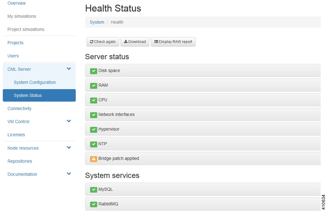
Note | When an issue is discovered, a red x is displayed next to the entry. Click the entry to view further details. |
Connectivity
Within the User Workspace Management interface, the Connectivity page provides details on all OpenStack ports available on the external (FLAT and SNAT) and project management networks.
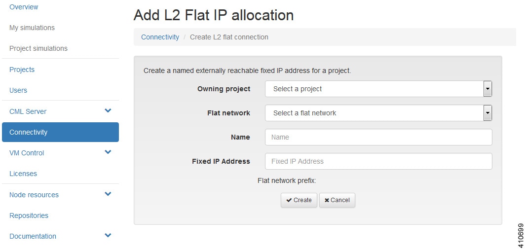
- L2 FLAT IP address allocations—Create an externally reachable fixed IP address for a project.
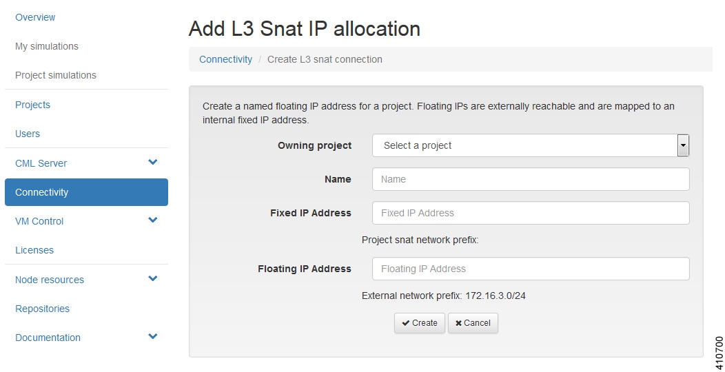
- L3 SNAT IP address allocations—Create a floating IP address for a project. Floating IPs are externally reachable and are mapped to an internal fixed IP address.
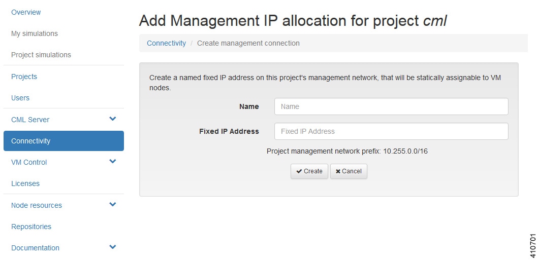
- Project Management IP address allocations—Create a fixed IP address on the management network of the selected project. This IP address can be statically assigned to the nodes.
Create a Port Connection
To create a new port connection, complete the following steps:
| Step 1 | In the User Workspace Management interface, click Connectivity. The Outside Connections page, which lists all current port connections appears. | |||||||||||||||||||||||||||||||||
| Step 2 | Connections are
grouped into three areas:
L2 FLAT,
L3 SNAT, and
Project
Management. Click
Add in the
applicable group to create the required port connection for that type.
The corresponding Add IP Allocation page appears. | |||||||||||||||||||||||||||||||||
| Step 3 | Complete the
fields as required for the applicable port connection.
| |||||||||||||||||||||||||||||||||
| Step 4 | Click
Create.
The new connection is created and its details are displayed in the Connectivity page. |
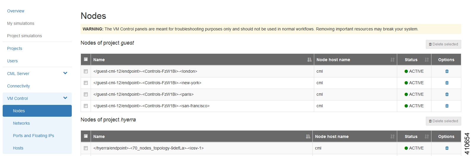
Using the VM Control Tool (Admin User)
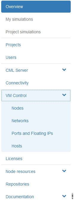
VM Control Nodes
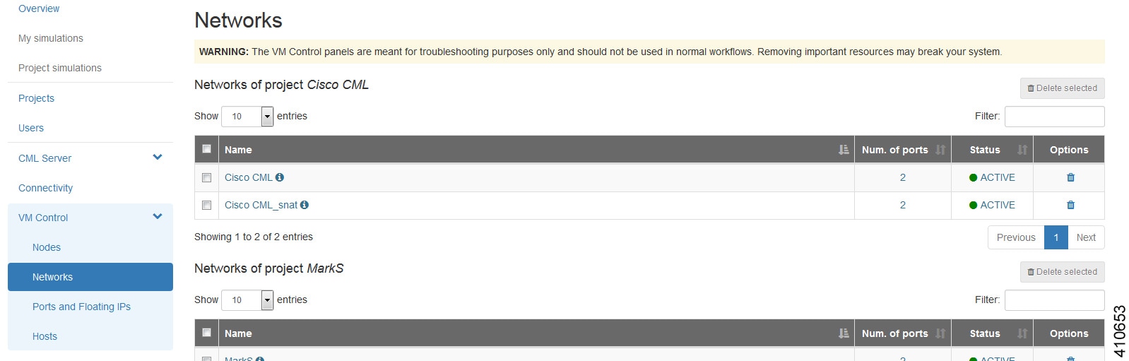
VM Control Networks
VM Control Ports and Floating IPs
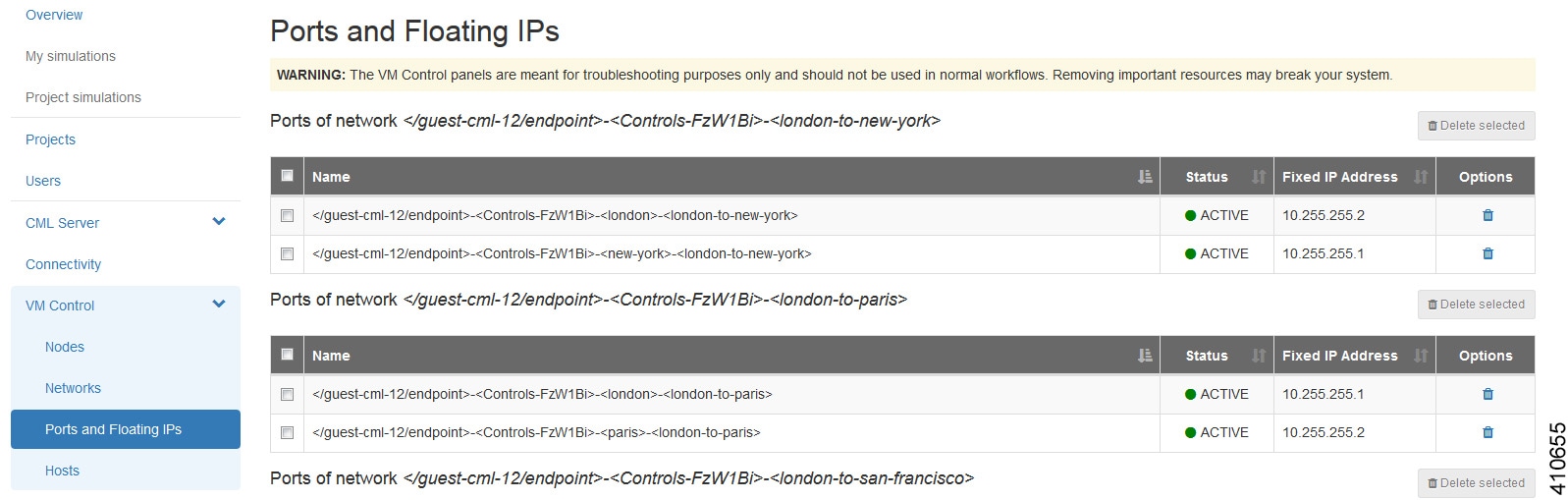
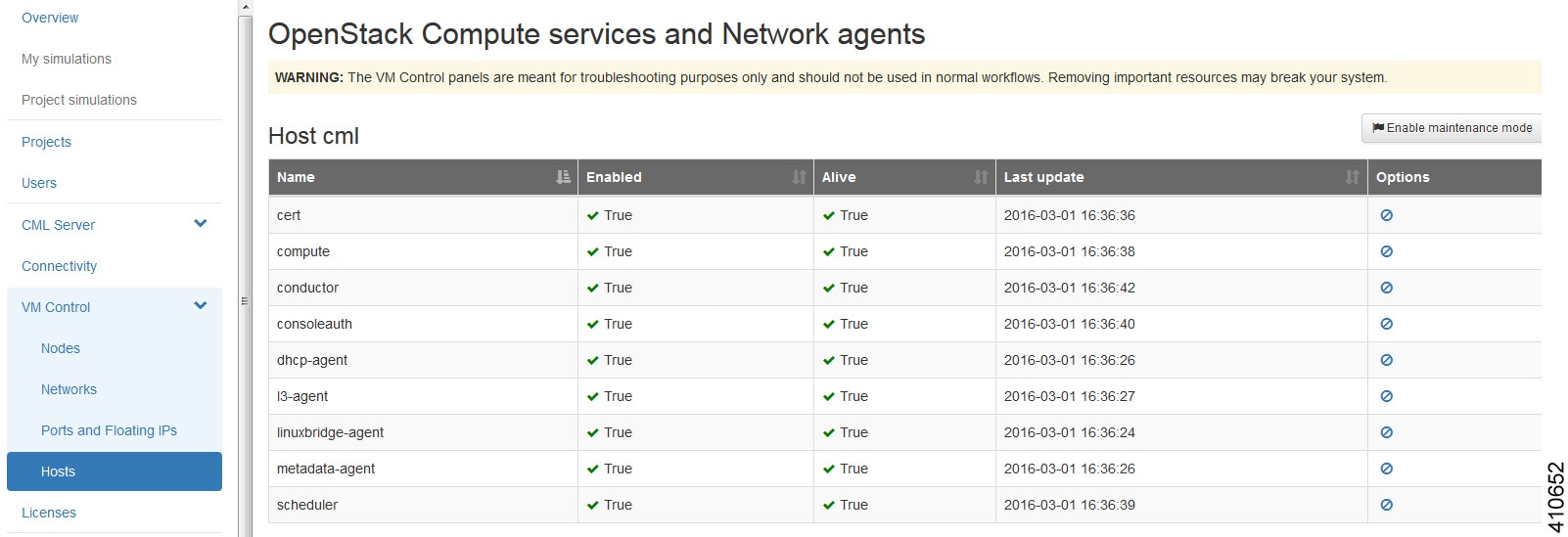
VM Control Hosts
The Hosts page lists all the compute services and network agents. Maintenance mode on a host disables the compute service on that node. It prevents new virtual machines from being deployed on that host.
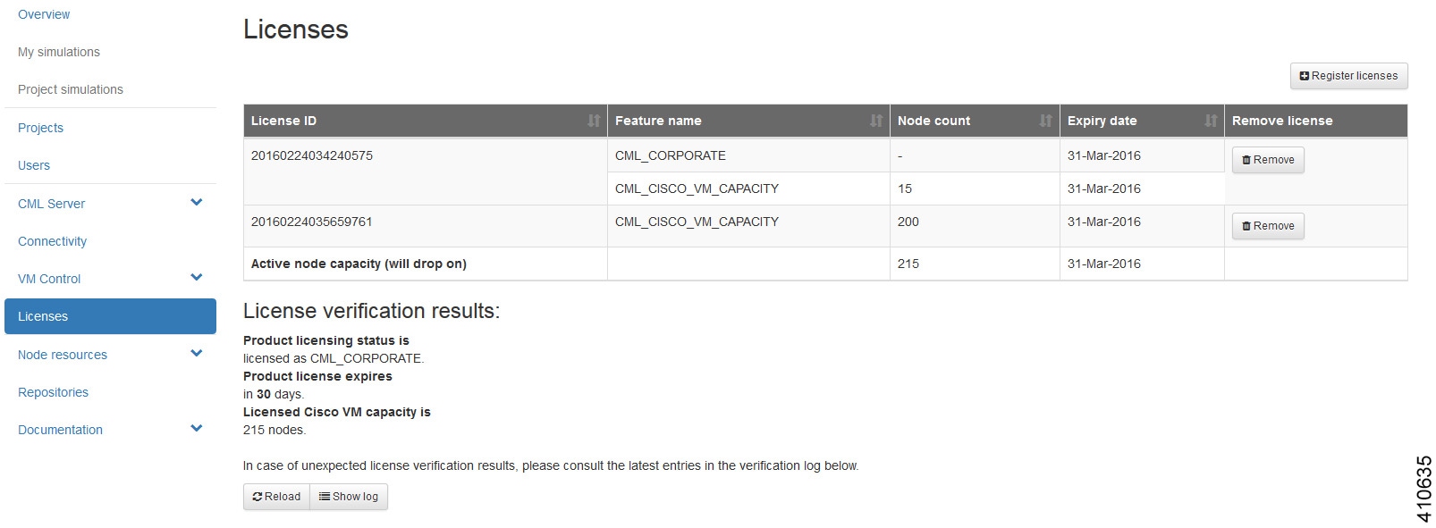
Cisco Modeling Labs Licenses (Admin User)
Within the User Workspace Management interface, you can manage Cisco Modeling Labs licenses. A license specifies the options that are enabled for Cisco Modeling Labs.
Register a Cisco Modeling Labs License
| Step 1 | Open the email containing your Cisco Modeling Labs license key. |
| Step 2 | Using a text editor, open the attached .lic file. |
| Step 3 | In the User Workspace Management interface, click Licenses. The Licenses page, which lists all valid licenses, appears. |
| Step 4 | Click Register License to
register a valid license.
The
Register
licenses page appears.
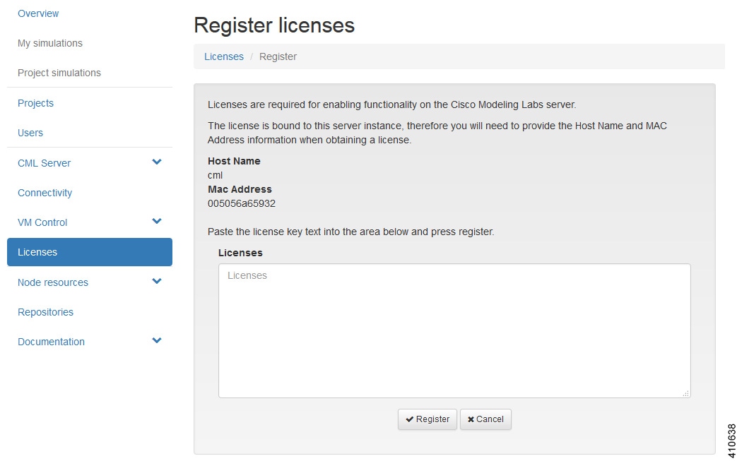 |
| Step 5 | Copy and paste the license key from the .lic file into the Licenses text area. |
| Step 6 | Click Register. The license is applied. |
| Step 7 | Return to the Licenses page to view the newly registered license. |
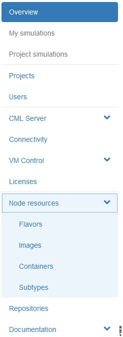
Node Resources
Within the User Workspace Management interface, under Node Resources, you can manage virtual machine run-time parameters and virtual machine images. You can also manage LXC container images and templates.
Virtual Machine Flavors
Within the User Workspace Management interface, as part of the creation process for virtual machine images, a virtual machine flavor is created. Flavors are used in each virtual machine to define the CPU, memory (RAM) allocation, disk space, the number of cores, and so on.
|
Operation |
Description |
|---|---|
|
Add |
Creates a new flavor. |
|
Delete |
Deletes a selected flavor. |
Create a Virtual Machine Flavor
To create a new virtual machine flavor, complete the following steps:
| Step 1 | In the
User Workspace
Management interface, in admin mode, click
Flavors.
The Flavors page, which lists all of the available flavors, appears. |
| Step 2 | Click
Add to
create a new flavor.
The Create Flavor page appears. 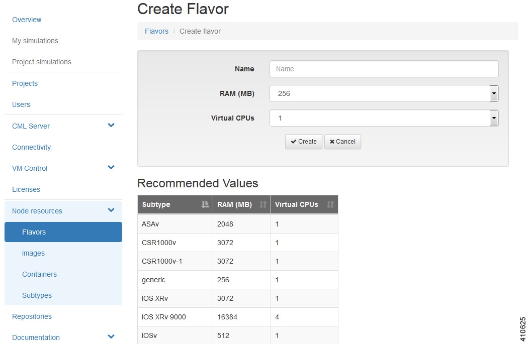 |
| Step 3 | In the Name field, enter a name for the flavor. |
| Step 4 | From the RAM drop-down list, choose the amount of memory allocation for the flavor. |
| Step 5 | From the Virtual CPUs drop-down list, choose the number of virtual CPUs for the flavor. |
| Step 6 | Click
Create to
create your virtual machine flavor.
The Flavors page appears with the newly created flavor listed. |
| Step 7 | Under the Options column, use the Delete option to delete a virtual machine flavor. |
Images
Within the User Workspace Management interface, you can add new images, update details for existing images, or delete images from the system. Additionally, you can take a snapshot of the disk content of a virtual machine image. This newly created user-specific disk image can be used in other simulated sessions.
-
Cisco Virtual IOS (IOSv) Software Release 15.6(2)T
-
Cisco IOSv Layer 2 Switch Software Release 15.2.(4.0.55) DSGS
-
Cisco IOS XRv Software Release 6.0.1 CCO
-
Linux server (Ubuntu 14.04.2 LTS Cloud-init)
-
Cisco ASAv Software Release 9.5.1
|
Operation |
Description |
|---|---|
|
Add |
Creates a new virtual machine image. |
|
Modify |
Modifies details for a selected virtual machine image. |
|
Delete |
Deletes a selected virtual machine image. |
Create a Virtual Machine Image
To create a new virtual machine image, complete the following steps:
| Step 1 | In the
User Workspace
Management interface, log in as admin and click
Images.
The Images page, which lists all of the available registered images, appears.
| ||
| Step 2 | Click
Add to
create a new image.
The Create VM Image page appears. 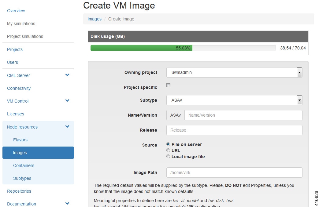 | ||
| Step 3 | From the Owning Project drop-down list, choose the appropriate project for the new image. | ||
| Step 4 | Click the Project Specific check box if you want the new image to be private and only available to the owning project. | ||
| Step 5 | From the Subtype drop-down list, choose the appropriate subtype for the new image. | ||
| Step 6 | In the Name/Version field, enter a name or version number for the image. | ||
| Step 7 | In the Release field, enter the release number for the image. | ||
| Step 8 | Click the appropriate Image Source: File on Server, URL, or Local Image File. | ||
| Step 9 | In the Image Path field, enter a path on the server/virtual machine (an HTTP, FTP or TFTP URL) or choose a file to upload. | ||
| Step 10 | To upload an image from your own device, click Browse to navigate to the image file. | ||
| Step 11 | Click
Create to
create your virtual machine image.
The Image <Image Name> page, which contains the details and properties of the virtual machine image, appears. | ||
| Step 12 | Click Images to view the newly added image. | ||
| Step 13 | Under the Options column, use the Modify or Delete options to amend the details for the virtual machine or to delete a virtual machine image. After the image is installed, it is available for users to select for their topology simulation. | ||
| Step 14 | In the
Cisco Modeling Labs client, click
.
The
Node Subtypes dialog box is displayed.
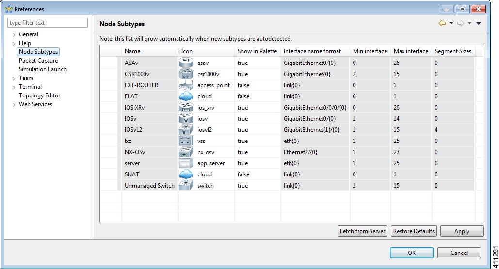 | ||
| Step 15 | In the Node Subtypes dialog box, click Fetch from Server. The Confirm dialog box is displayed. | ||
| Step 16 | Click OK to update the list of node subtypes based on the currently configured Cisco Modeling Labs server. |
Create an Image Snapshot
When a Linux server is present in a running simulation, you can take a snapshot of the disk content of the server. This newly created user-specific disk image can be used in other simulated sessions.
To take a snapshot of the server's disk content, complete the following steps.
| Step 1 | Log in to the
User Workspace
Management interface.
| ||
| Step 2 | On the Overview page, under Sessions, choose the applicable running session. A list of active virtual machines is displayed. | ||
| Step 3 | Choose the
applicable virtual machine image, and under the
Options
column, click the
Create
Snapshot icon.
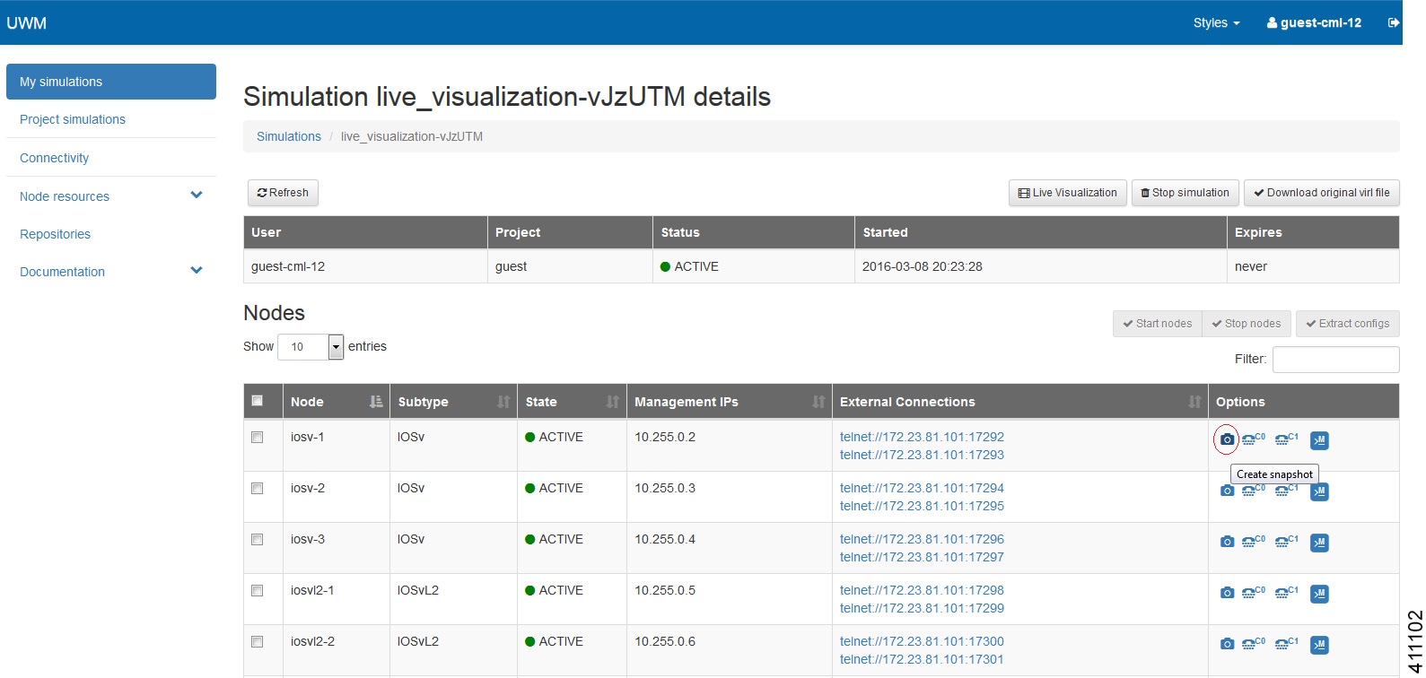 Project details for the newly created snapshot are displayed. 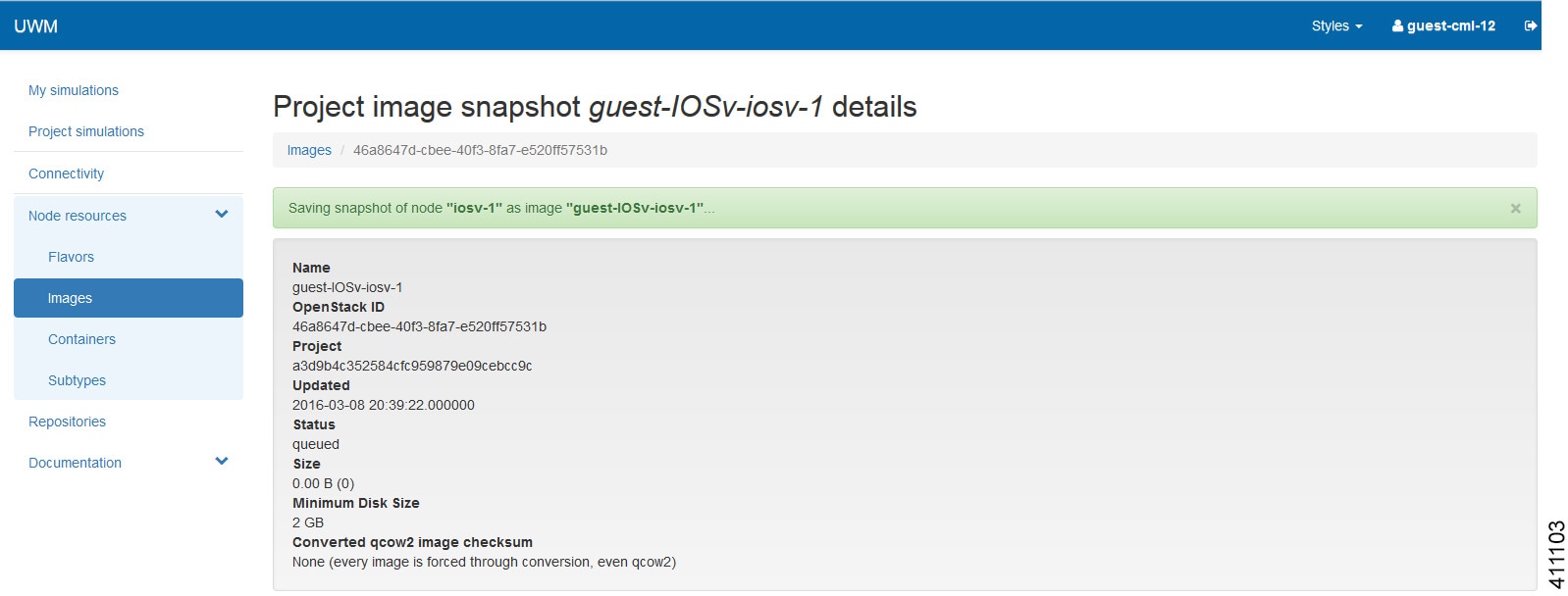 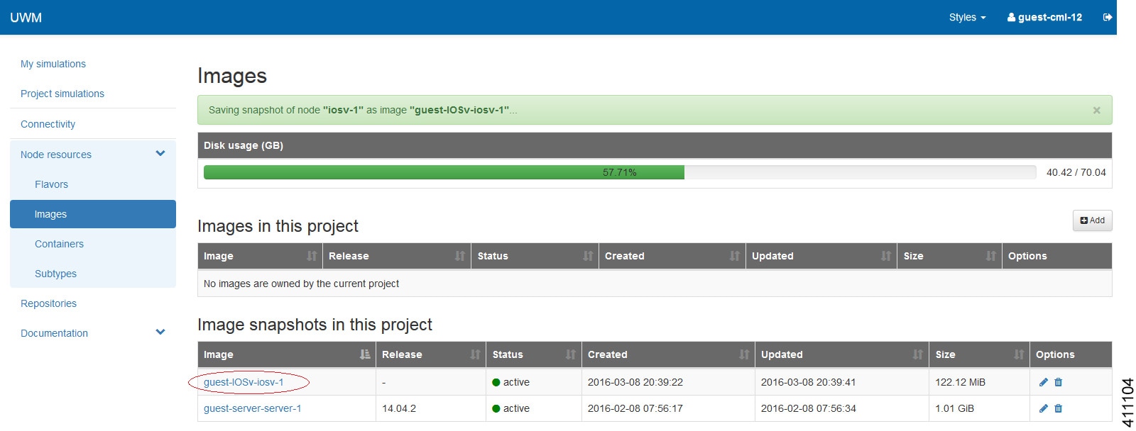 The image snapshot can be reused in the Cisco Modeling Labs client under See Cisco Modeling Labs Corporate Edition User Guide, Release 1.2 for more information. |
Containers
In the User Workspace Management interface, the Containers page provides a list of LXC images and templates. Here you can manage LXC container images and templates.
|
Operation |
Description |
|---|---|
|
Add |
Create a new LXC image and/or LXC template. |
|
Modify |
Modify details for LXC images |
|
Delete |
Delete LXC images and templates as required. |
Create an LXC Image
To create a new LXC image, complete the following steps:
| Step 1 | Click
in the
User Workspace
Management interface.
The Containers page, which lists all of the available LXC images and templates, appears. |
| Step 2 | Click
Add to create a new LXC image.
The Create LXC Image page appears. 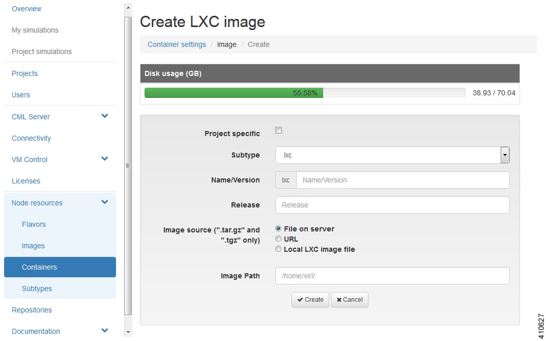 |
| Step 3 | Click the Project Specific check box if you want the new image to be private and only available to the owning project. |
| Step 4 | Choose the appropriate subtype for the new LXC image from the Subtype drop-down list. |
| Step 5 | Enter a name or version number for the image in the Name/Version field. |
| Step 6 | Enter the release number for the image in the Release field. |
| Step 7 | Click the appropriate Image Source: File on Server, URL, or Local Image File. |
| Step 8 | Enter a path on the server/virtual machine (an HTTP, FTP or TFTP URL) or choose a file to upload in the Image Path field. |
| Step 9 | Click Browse to navigate to the LXC image file to upload an image from your own device. |
| Step 10 | Click Create to create your LXC image. |
| Step 11 | Click Images to view the newly added image. |
| Step 12 | Under the Options column, use the Modify or Delete options to amend the details for the LXC image or to delete an LXC image. After the LXC image is installed, it is available for users to select for their topology simulation. |
Create an LXC Template
To create a new LXC template, complete the following steps:
| Step 1 | Click
in the
User Workspace Management interface.
The Containers page, which lists all of the available LXC images and templates, appears. |
| Step 2 | Click
Add to
create a new LXC template.
The Create LXC Template page appears. 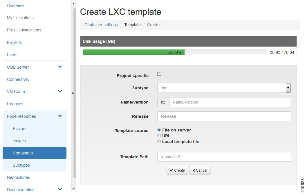 |
| Step 3 | Click the Project Specific check box if you want the new image to be private and only available to the owning project. |
| Step 4 | Choose the appropriate subtype for the new LXC image from the Subtype drop-down list. |
| Step 5 | Enter a name or version number for the image in the Name/Version field. |
| Step 6 | Enter the release number for the image in the Release field. |
| Step 7 | Click the appropriate Template Source: File on Server, URL, or Local Image File. |
| Step 8 | Enter a path on the server/virtual machine (an HTTP, FTP or TFTP URL) or choose a file to upload in the Template Path field. |
| Step 9 | Click Browse to navigate to the LXC image file to upload from your own device. |
| Step 10 | Click Create to create your LXC template. |
| Step 11 | Click Images to view the newly added LXC template. |
Subtypes
In the User Workspace Management interface, the Subtypes page provides a list of integrated subtypes, which users can use as templates to create their own custom subtypes. Using the Specialize option for a subtype, a user can duplicate the subtype template and make the necessary updates to create a new custom subtype. Subtypes can be imported and exported, which allows users to apply their custom subtypes to other Cisco Modeling Labs server installations.
|
Operation |
Description |
|---|---|
|
Import |
Imports a subtype from a JSON file. |
|
Export |
Exports a subtype to a JSON file. |
|
Specialize |
Duplicates an available subtype to create a custom subtype. |
Import a Subtype
Subtypes for import must be available in a JSON file.
To import a subtype, complete the following steps:
| Step 1 | Click Subtypes in the User Workspace Management interface, under Node Resources. The Subtypes page, which lists the integrated subtypes, appears. |
| Step 2 | Click
Import to
import a new subtype.
The Import Subtypes page appears. |
| Step 3 | Paste the subtype details from the JSON file into the text area. |
| Step 4 | Click Import. The newly imported subtype is listed on the Subtypes page. |
| Step 5 | (Optional) Click Specialize to create a custom subtype based on the newly imported subtype, click Modify to amend the details for the subtype, or click Delete to delete the subtype. |
Create a Custom Subtype
To create a custom subtype, complete the following steps:
| Step 1 | In the User Workspace Management interface, under Node Resources, click Subtypes. The Subtypes page, which lists the integrated subtypes available, appears. | ||||||||||||||||||||||||||||||||||||||||||||||||||||
| Step 2 | For the applicable subtype, under the Options column and click the Specialize icon. The Specialize Subtype page appears. | ||||||||||||||||||||||||||||||||||||||||||||||||||||
| Step 3 | Update the
subtype fields as required.
| ||||||||||||||||||||||||||||||||||||||||||||||||||||
| Step 4 | When completed,
click
Create to
create the new custom subtype.
The new
subtype is created and its details are displayed in the
Subtypes page for the new subtype.
| ||||||||||||||||||||||||||||||||||||||||||||||||||||
| Step 5 | (Optional) On this page, you can click Specialize to create a custom subtype based on the newly created subtype, click Modify to amend the details for the subtype, or click Delete to delete the subtype. | ||||||||||||||||||||||||||||||||||||||||||||||||||||
| Step 6 | Click the Subtypes tab to see the custom subtype listed on the page. |
Documentation
Within the User Workspace Management interface, you can access STD API and User Workspace Management API documentation. It is available from .
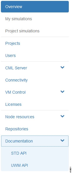
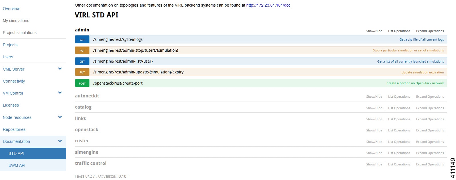
To access the STD API, click STD API. The STD API page is displayed.
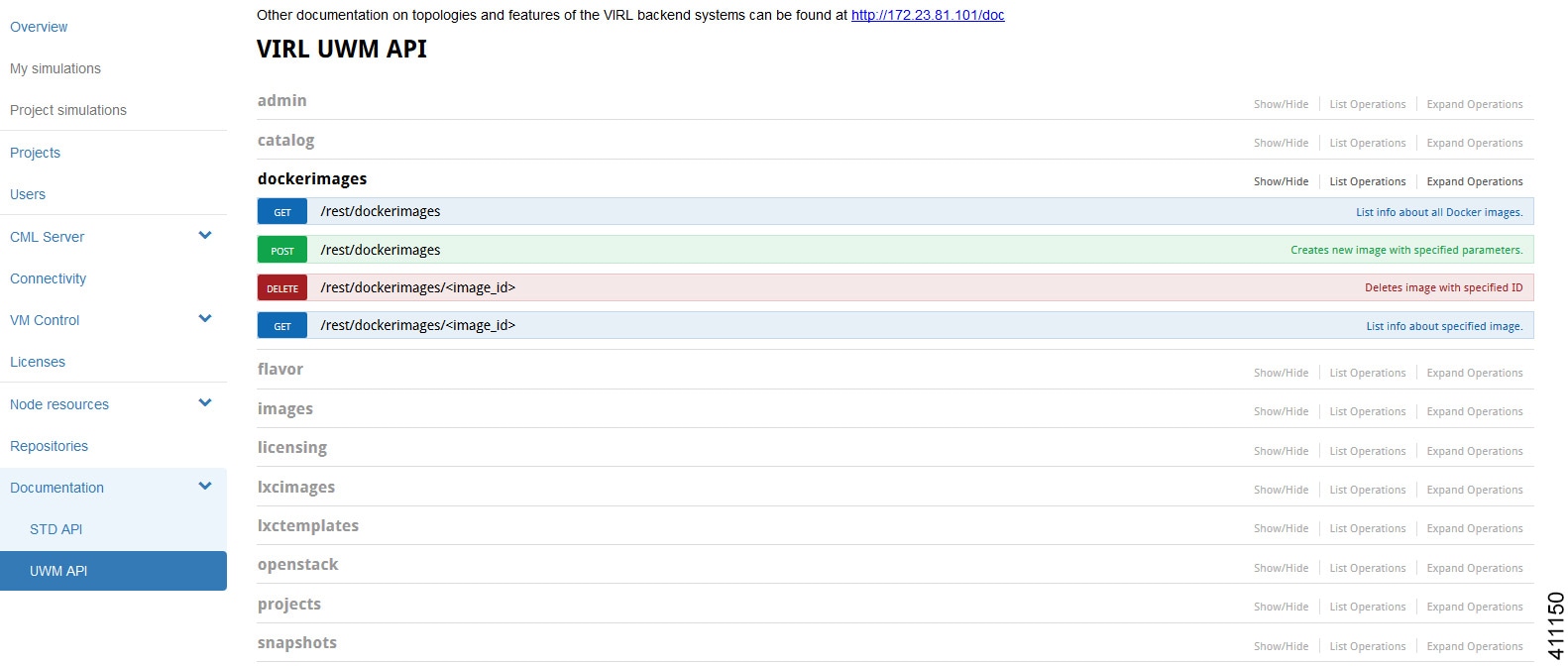
To access the User Workspace Management API, click UWM API. The UWM API page is displayed.
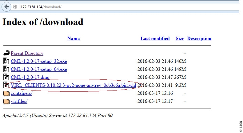
Python Client Libraries
Cisco Modeling Labs provides Python Client Libraries for STD and UWM services. These are available as .whl files that can be downloaded from http://<IP address>/download/ with installation information at http://<IP address>/doc/clients.html. The package can be installed using the command sudo pip install <filename>.whl. This provides the Cisco Modeling Labs STD, UWM and Openstack CLIs and client modules which can be imported into your Python projects.
The pydoc function is available for these modules and can be accessed by issuing the commands pydoc virl_client.std, pydoc virl_client.uwm and pydoc virl_client.openstack. Help can be obtained by issuing the commands virl_std_client --help, virl_uwm_client --help and virl_openstack_client --help. The .whl file does not need to be installed on the CML server as it is already installed. The modules should be installed on your local Linux workstation. These .whl files are specifically for Linux only.
 Feedback