Cisco Modeling Labs Corporate Edition System Administrator Installation Guide, Release 1.2
Bias-Free Language
The documentation set for this product strives to use bias-free language. For the purposes of this documentation set, bias-free is defined as language that does not imply discrimination based on age, disability, gender, racial identity, ethnic identity, sexual orientation, socioeconomic status, and intersectionality. Exceptions may be present in the documentation due to language that is hardcoded in the user interfaces of the product software, language used based on RFP documentation, or language that is used by a referenced third-party product. Learn more about how Cisco is using Inclusive Language.
- Updated:
- July 10, 2016
Chapter: Installation Prerequisites
Installation
Prerequisites
Cisco Modeling Labs Server Requirements
This section details the hardware and software requirements for installing the Cisco Modeling Labs server.
The following table lists hardware requirements that are based on the number of virtual nodes used.
| Requirement | Description |
|---|---|
| Disk Space | 250 GB minimum |
| Chip Set | Intel® with Intel virtualization technology VT-x and extended page tables (EPT) |
| Hypervisor | VMware ESXi 5.1 U2, ESXi 5.5 U1, ESXi 6.0 (Build 2494585) |
| Server type for OVA package | Any server with Intel virtualization technology VT-x and extended page tables (EPT) |
| Server type for ISO package | Supported only on Cisco UCS servers with local storage |
| Server Recommendation | Cisco UCS C220 M4 and Cisco UCS C420 M4 |
The recommended servers for Cisco Modeling Labs are the Cisco UCS C220 M4 and Cisco C420 M4 servers.
For more information on UCS servers, see the applicable data sheets at http://www.cisco.com/c/en/us/products/servers-unified-computing/ucs-c-series-rack-servers/index.html.
For bare metal installations, Cisco Modeling Labs ISO package is certified only with the Cisco UCS C220 M4 and Cisco C420 M4 servers.
Sizing the Server: Number of Cores and Memory Requirements
The general rule of thumb is three virtual nodes to one physical core CPU for simulation of 49 nodes and below, and two virtual nodes to one physical core CPU for 50 nodes and above.
 Note | In order to size the Cisco Modeling Lab Server resources, you must use the Cisco Modeling Labs resource calculator available at http://www.cisco.com/go/cml |
| Requirement | Description | ||
|---|---|---|---|
| VMware | |||
| VMware vSphere | Any of the following:
|
||
| Browser | Any of the following:
|
|
Name |
Description |
||||
|---|---|---|---|---|---|
|
Intel Hyper-Threading Technology |
|
||||
|
Intel VT |
|
||||
|
Intel VT-d |
|
Planning Network Configurations on VMware ESXi Servers
Cisco Modeling Labs can be set up in a variety of ways to meet the requirements of end users. Prior to setting up the ESXi server for the Cisco Modeling Labs server, we recommend that you create an installation plan that considers the following factors:
-
Provide end-user access to the Cisco Modeling Labs server
Cisco Modeling Labs has a server-client architecture. The client is Java-based and uses several well know and custom ports to communicate with the server. If there is a firewall in the lab between the client and the Cisco Modeling Labs server, it should be configured as to allow these sessions to pass. The User Workspace Management interface is web-based and uses specific TCP ports to configure and manage the server resources. After a simulation is started, end users connect to the specific IP address and port number of the node’s management ports. This is done using either the Cisco Modeling Labs client GUI’s Telnet functionality or a third-party Telnet client. For a list of all of the User to Cisco Modeling Labs Server ports, refer to the Cisco Modeling Labs Default Port Numbers section.
As a system administrator, you should determine if end users will access the Cisco Modeling Labs server only when they are on an internal network, such as a lab network, or if they need access to the server via the Internet. If end users plan to access the Cisco Modeling Labs server remotely, you should plan their access accordingly.
-
Provide direct access to the virtual topologies
After end users create their virtual topologies and launch their simulations, they may connect to the nodes in the topologies in numerous ways. Understanding the access needs is important for determining the configuration and IP address details for the ESXi server and the Cisco Modeling Labs server.
There are three access strategies to consider:
-
End users bypass the Cisco Modeling Labs client and connect directly to nodes (Using the node's out-of-band [OOB] management interface through the FLAT interface)
When the simulation is configured to use a Shared Flat Network as the Management Network, each node within the topology is configured such that its first interface (e.g., GigabitEthernet0/0) is assigned with an IP address associated with the Flat interface (by default, from the 172.16.1.0/24 range). This represents the node's OOB_Management interface. All OOB_Management interfaces are connected to a shared management network segment known as FLAT.
When OOB_Management access is required, the Cisco Modeling Labs server uses a specific configuration that enables a bridge segment on the Ethernet 1 port. External devices that attach to the Ethernet 1 port, using the correct IP address are then able to communicate directly with the nodes. The simulation continues to be driven by an end user via the Cisco Modeling Labs client GUI communicating with the Cisco Modeling Labs server at its IP address bound to the Ethernet 0 port.
-
In-band IP access using FLAT
Consider this option when end users have to connect to one or more nodes in a running simulation to an external networking device, and the interconnecting link can carry both data-plane and management plane traffic. In other words, end users need to pass data-plane and control plane packets from external devices, such as routers or traffic generators, into the nodes running in a network simulation. With this method, end users associate the FLAT network object in the GUI to a virtual node's interface. Virtual nodes associated with a FLAT network object are assigned an IP address from the FLAT address pool (by default, 172.16.1.0/24). This network segment is bridged to the Cisco Modeling Labs server's Ethernet 1 port.
External devices attached to the Ethernet 1 port are able to pass packets to the interconnected nodes, and may also be used for Telnet sessions to, or launched from the virtual node to other virtual nodes in the simulation. The simulation continues to be controlled by the user via the Cisco Modeling Labs client GUI. The Cisco Modeling Labs server reserves two interfaces for bridging external traffic into running topology simulations. By default, inserting a FLAT network object on the Cisco Modeling Labs client design canvas will use the first FLAT interface. Modifying the object's configuration can enable the use of the second interface, FLAT1. By default, virtual node interfaces associated with the FLAT1 port (Ethernet 2) will be assigned IP addresses from the 172.16.2.0/24 range.
When using FLAT or FLAT1 objects, external nodes on the common subnet may ping, trace route, or connect via Telnet directly to the associated virtual node. Adding the appropriate static/default routes on the virtual node associated with the FLAT/FLAT1 objects and advertising it (using the configured routing protocol) within the simulation can extend this connectivity to the other virtual nodes. Making similar routing adjustments on the external node integrated with the simulation environment can extend IP connectivity to physical endpoints beyond the gateway device.
-
In-band access using Static Network Address Translation (SNAT)
The SNAT network object provides a Layer-3 based approach to integrating external devices with topology simulations. This method leverages an integral OpenStack-controlled NAT gateway to facilitate static mapping of external IP addresses (by default, 172.16.3.0/24) to internal IP addresses (generally in the 10.254.0.0/24 range). The SNAT interface is bound to the Ethernet 3 port. The SNAT approach is used when the internal particulars of the network simulation are hidden from the external devices.
Upon launching the simulation from the Cisco Modeling Labs client, the internal and external IP addresses assigned to the SNAT integration are presented in the Simulation perspective. Alternatively, the assigned mappings may be referenced via the Cisco Modeling Labs server's User Workspace Management interface.
-
-
Determine your IP addressing plan
The following are the key points to note when determining your IP addressing plan for the ESXi server and the Cisco Modeling Labs server: -
When using the OVA-based deployment, the Cisco Modeling Labs management interface (Ethernet 0) is initially set to use DHCP to acquire host addressing details. We recommended that this is changed to a static assignment immediately after installing the software within the ESXi host.
-
It is not recommended to enable public Internet access to the Cisco Modeling Labs management interface. If remote access is required, proper security considerations should be applied to prevent unauthorized access (e.g., VPN access, ACLs) As a lab/test focused system, no provision has been made for maintaining/applying security related patches to the underlying Ubuntu operating system, thus unencumbered access can represent a security risk. In addition, allowing the included Open Source components to update automatically can introduce untested executables that may break the integration. By default, Cisco Modeling Labs applies rfc1918 private addresses to virtual nodes within simulations and to interfaces associated with node management/external device integration. This should prevent unintended access in cases of inadvertent leakage to outside of the lab domain.
-
By default, the following IPv4 address ranges are assigned by Cisco Modeling Labs upon launching a topology simulation and are associated with communications with external devices: These are system level assignments that are shared across all projects and simulations launched within a Cisco Modeling Labs server. The defaults are configured in the System Configuration section of the User Workspace Management interface and may be adjusted to meet existing lab integration requirements. If multiple instances of Cisco Modeling Labs servers are deployed, the default networks associated with the FLAT, FLAT1, and SNAT interfaces must be configured as to not overlap. -
By default, the following IPv4 address ranges are used by Cisco Modeling Labs AutoNetkit function upon building a topology simulation: Upon launching the simulation within the Cisco Modeling Labs server, these address assignments are typically constrained within that simulation’s environment. This is the same for any manually configured addressing applied to the simulation’s virtual nodes. However, conflicts can arise if the simulation is enabled to use external communications, and a routing protocol is enabled to advertise the virtual node’s networks externally. We recommend that any such advertisements from the simulation environment not be propagated outside of the designated lab environment.
-
-
Determine if you need to use VLANs in your configurations
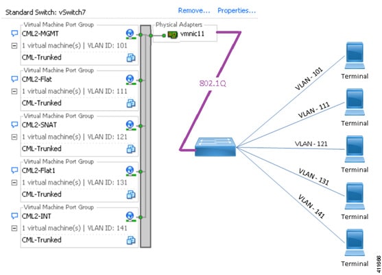
Cisco Modeling Labs requires five network interfaces to enable full functionality. If the server is fitted with the sufficient network interfaces, the application’s interfaces may be mapped on a 1:1 basis to vNICs associated with dedicated physical NICs to the adjacent access switch. Alternatively, deploying Cisco Modeling Labs within a VM allows these interfaces to be virtualized as Port Groups on a common ESXi vSwitch, and carried as VLANs across an 802.1q trunk to an adjacent access switch. The ESXi vSwitch can be set to tag the appropriate VLAN ID onto each frame based on its originating Port Group, and direct appropriately tagged incoming frames to the designated Port Group. The adjacent switchport is configured as a trunk, and set to pass the VLAN IDs associated with the Cisco Modeling Labs.
For bare-metal deployments using the ISO-formatted distribution file, the compute platform should have all five network interface ports installed in the system prior to initiating the installation. For servers fitted with less than the recommended ports, the missing ports may be “dummied.” Binding the application interfaces to a dummy-port will reduce the external communications options for that Cisco Modeling Labs deployment.
For either VM or bare-metal deployments, it is possible to extend VLANs into the simulation as a method to aggregate multiple Layer-3 connections into the project simulation. The involved Port Groups must be optioned to pass all tagged frames. We recommend that the adjacent switchport be configured as to prune any VLAN not destined for the Cisco Modeling Labs server.
-
During the initial setup of the Cisco Modeling Labs server, the System Configuration section of the User Workspace Management interface provides configuration values, such as, static configuration of the Cisco Modeling Labs management interface and the IP address ranges associated with external networking via the FLAT/FLAT1 or SNAT interfaces. You should follow the installation instructions to set selected parameters during the installation process.
Installation Methods
There are a variety of installation methods that enable interconnection of the Cisco Modeling Labs interfaces to external devices.
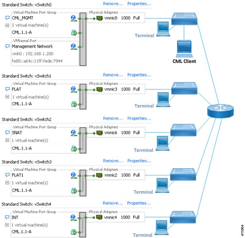
Depending on the number of physical NICs being allocated to Cisco Modeling Labs connections, other Port Group to vSwitch combinations may be employed. Each of the Port Groups's security policies must be configured to allow Promiscuous Mode.
A single physical adapter should be used for each vSwitch associated with the Cisco Modeling Labs application. ESXi's NIC-teaming feature is not recommended for vSwitch connections (either dedicated or shared/trunked) to external devices. See the External Connectivity chapter in the Cisco Modeling Labs Corporate Edition User Guide, Release 1.2 for more information.
Cisco Modeling Labs Default Port Numbers
This section details the default port numbers that are provided in Cisco Modeling Labs.
Note | These default port numbers are required for communication between the Cisco Modeling Labs server and the Cisco Modeling Labs client. If employed, firewalls between the two devices must be configured to permit these session flows. These values can be updated as required by the system administrator for your Cisco Modeling Labs server installation. |
|
Port Number |
Description |
|---|---|
|
19399 |
Services Topology Director—Generates OpenStack calls for the creation of nodes and links based on the XML topology definition created in Cisco Modeling Labs client. |
|
19400 |
User Workspace Management—Provides a web interface used to manage accounts, user projects, licenses, and virtual machine (VM)images on the Cisco Modeling Labs server. See the chapter "Access the User Workspace Management Interface" for more information. |
|
19401 |
AutoNetkit Visualization—Provides a graphical representation of the topology displayed in a web browser. See the chapter Visualizing the Topology in Cisco Modeling Labs User Guide, Release 1.2 for more information. |
|
19402 |
Live Visualization—Provides a live representation of a running simulation displayed in a web browser. See the chapter Visualizing the Topology in Cisco Modeling Labs User Guide, Release 1.2 for more information. |
|
6080, 6081 |
Virtual Network Computing (VNC) access to virtual machines—Allows you to connect to the Cisco Modeling Labs server using VNC, if enabled. |
|
6083 |
WebSocket Connection Proxy—Allows you to use Telnet over WebSocket to ports on a particular node. |
|
17000-18000 |
Serial Console Connections—Indicates the value range for connecting using Telnet to serial ports on nodes. |
|
22 |
Linux: Used for SSH sessions to jumphost within project/simulation. |
|
23 |
Linux: Telnet to virtual nodes when external communications is enabled. |
|
80 |
Linux: HTTP sessions to Cisco Modeling Labs server or virtual hosts within simulation. |
|
443 |
Linux: Default for Telnet over Websocket. |
|
3306 |
Linux: MySQL |
|
3333 |
Linux: HTTP |
|
5000 |
Linux: UPnP |
 Feedback