- Prepare for an OVA File Installation
- Download the Cisco Modeling Labs OVA File
- Configure Security and Network Settings
- Deploy the Cisco Modeling Labs OVA
- Edit the Virtual Machine Settings
- Customize the Cisco Modeling Labs Server Deployment
- (Optional) Configure Static IP
- Determine License Key Requirements
Cisco Modeling Labs
OVA Installation
Prepare for an OVA File Installation
There is a number of key prerequisites that must be in place in order to successfully install Cisco Modeling Labs using an OVA file.
These prerequisites are:
-
The host must support Intel VT-x/EPT virtualization extensions, and these extensions must be enabled in the BIOS.
-
The target disk must be at least 250 GB.
-
For installations to a VM, the following hypervisors are supported: -
VMware vSphere ESXi 5.5 Update 2 (Build 1993072) or later
-
VMware vSphere ESXi 6.0 (Build 2494585).

Note
Additionally, you must verify that you are using vSphere Client v5.5 Update 2 (Build 1993072) or later before deploying Cisco Modeling Labs. Failure to use this minimum version will result in a failed deployment that returns an error stating that nested virtualization is not supported.
Note
The implementation of Cisco Modeling Labs within a VM is limited to the listed VMware vSphere ESXi versions. Other hypervisors such as Oracle VirtualBox, Microsoft HyperV, XenServer, etc. are not supported. Depending on network speed and target platform performance, an installation can take between 30 and 60 minutes. -
Download the Cisco Modeling Labs OVA File
You must download the Cisco Modeling Labs OVA file using the link provided in your purchase confirmation email.
The OVA files are large (~4 GB), so rather than HTTP downloads using a web browser, the use of a download manager for Mac or Windows is recommended.
An MD5 hash sum for the OVA file is provided along with the download link on the download website. You must calculate and verify that the hash sum of the downloaded OVA file matches the source file:
Configure Security and Network Settings
Note | You must enable Intel VT in the BIOS for Cisco Modeling Labs to operate correctly. |
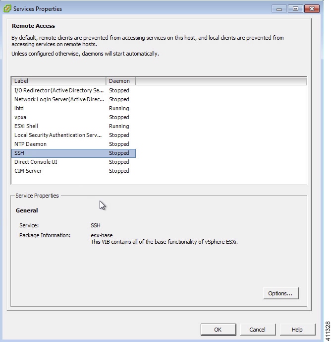
The ESXi host must be enabled for remote access using SSH sessions. This is necessary for Cisco’s Technical Support staff to provide diagnostic and corrective assistance should the need arise.
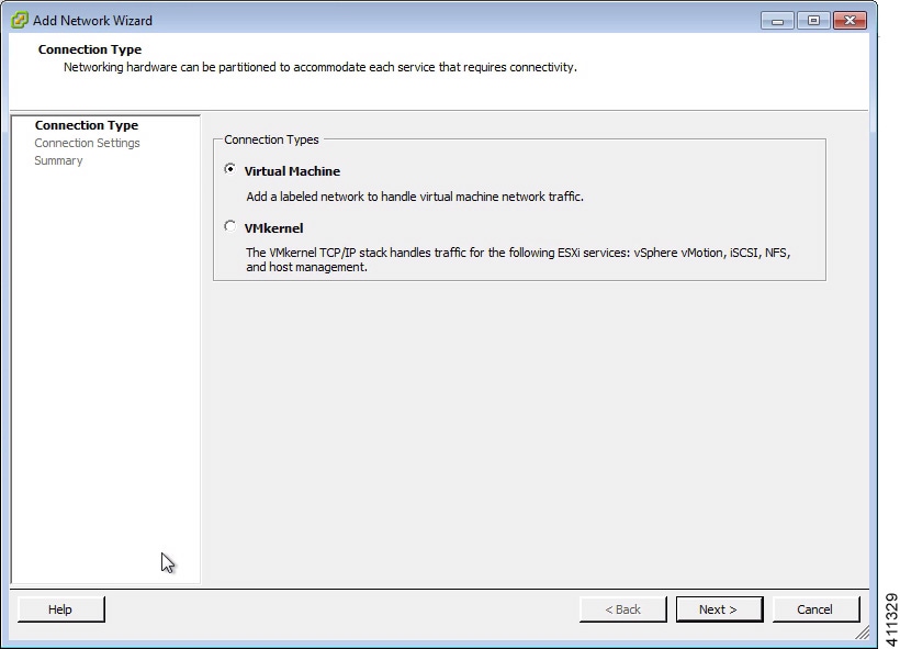
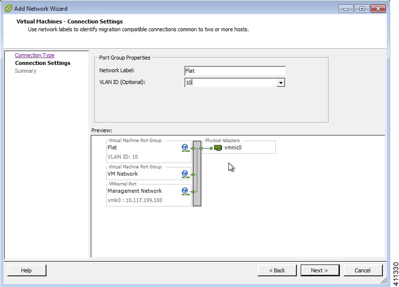
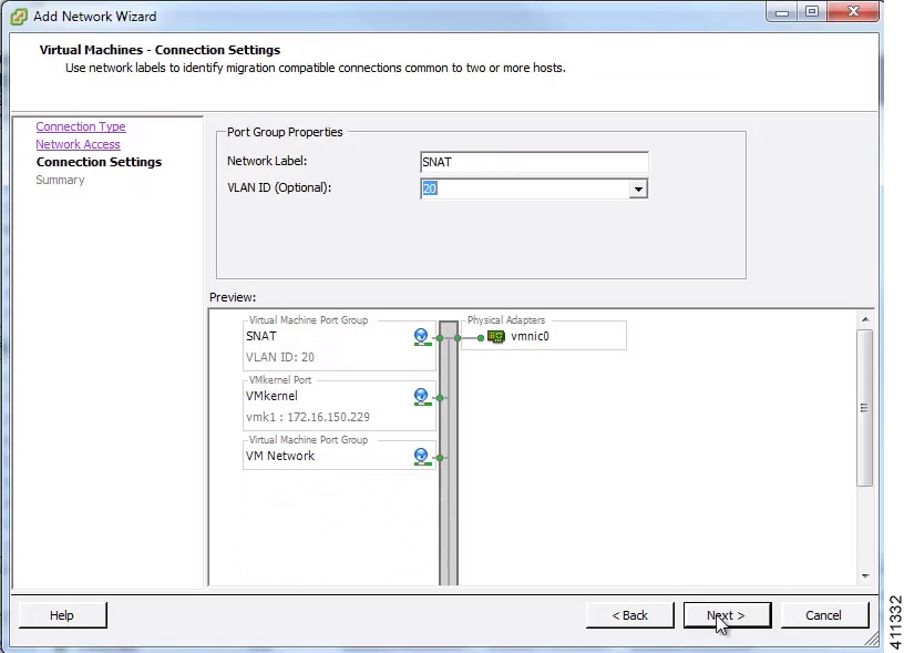
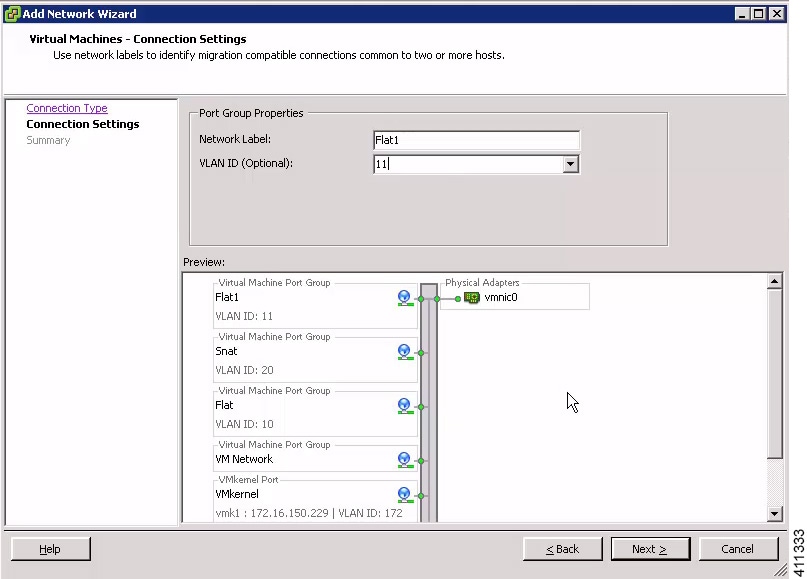
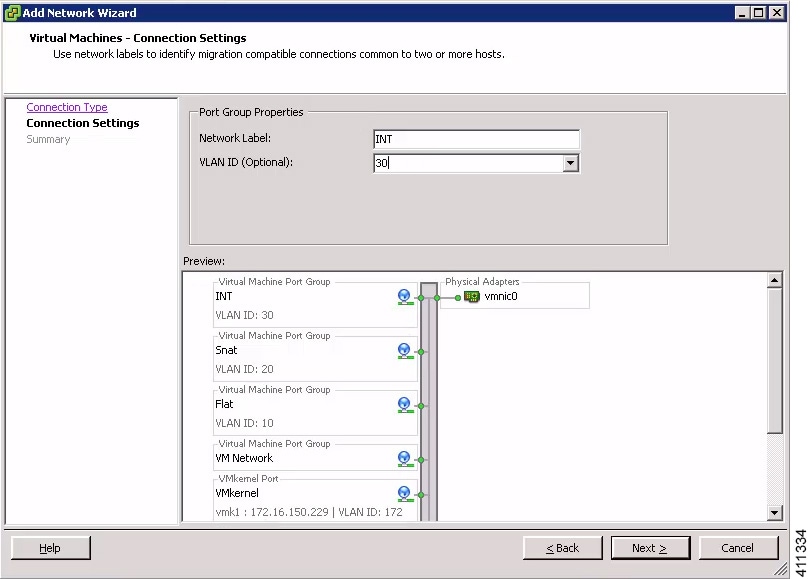
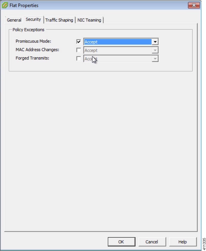
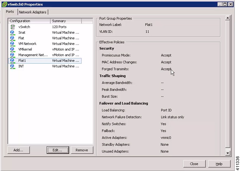
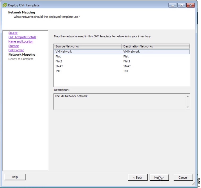
The Cisco Modeling Labs virtual machine requires connections to five distinct virtual network port groups. The first connection is for Cisco Modeling Labs server management, and is named VM_Network, by default. Depending on the vSphere deployment policies, this port group may be assigned to the same address space as the host’s VMkernel port (placing it on the same network), or on a distinct VLAN if isolation from the ESXi management is required. The other four port groups FLAT, FLAT1, SNAT, and INT are used by Cisco Modeling Labs for external communications. These ESXi port groups must be prepared prior to initiating the installation of Cisco Modeling Labs.
The following steps illustrates the most common deployment method of Cisco Modeling Labs in a VM environment.
- Ensure that you have met the requirements as specified in the section Cisco Modeling Labs Server Requirements.
- Ensure that you have administrator access to the VMware ESXi server in which you plan to deploy the Cisco Modeling Labs OVA in order to enable nested virtualization.
Deploy the Cisco Modeling Labs OVA
Verify your vSphere Client. Please verify that you are using vSphere Client v5.1 Update 2 (Build 1483097) or later before deploying Cisco Modeling Labs. Failure to use the minimum version will result in a failed deployment that will not support nested virtualization.
| Step 1 | To install the OVA, log in to the VMware ESXi server. | ||
| Step 2 | From the vSphere
Client menu, choose
.
 | ||
| Step 3 | Click Next. | ||
| Step 4 | In the Source screen, click Browse to navigate to the OVA package. | ||
| Step 5 | In the dialog box displayed, click Open. | ||
| Step 6 | Click
Next to review
the OVA details.
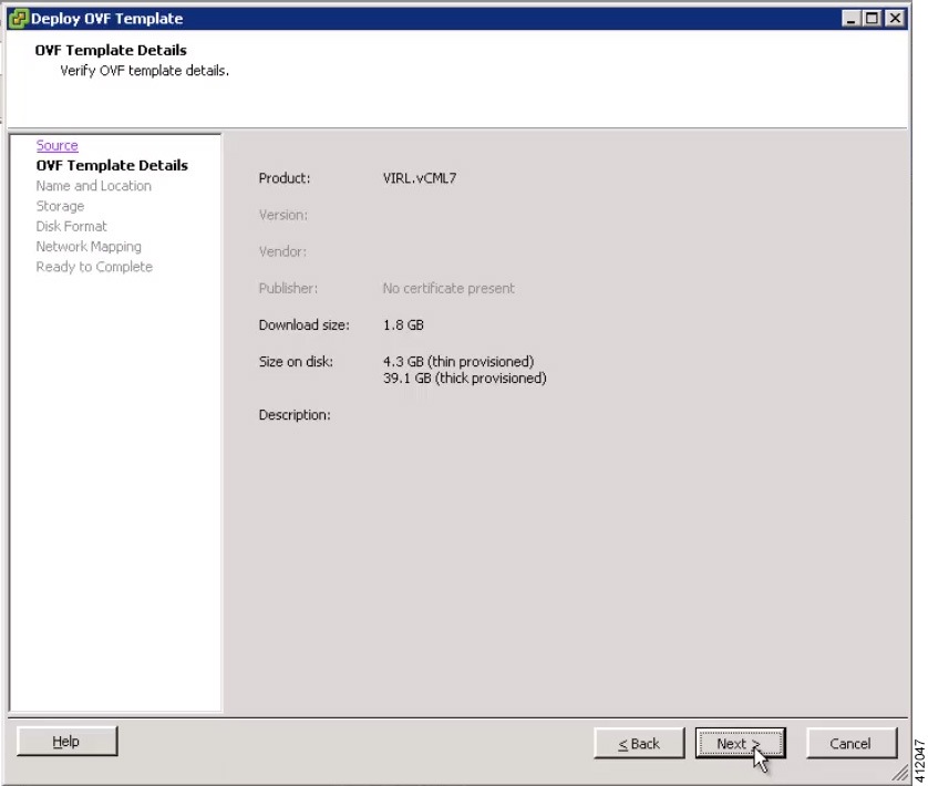 | ||
| Step 7 | Click Next. | ||
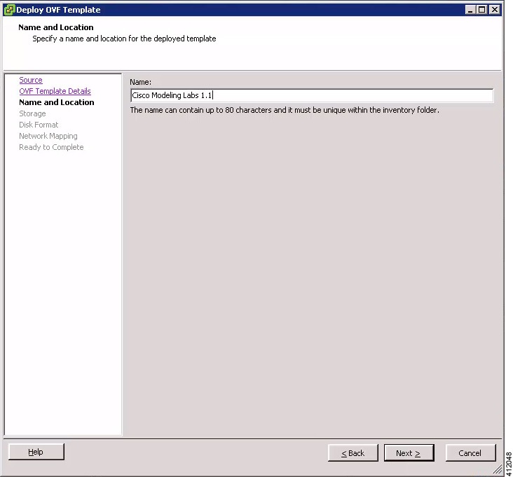
| Step 8 | In the
Name and
Location screen, confirm or provide a new name for the virtual
machine, for example,
Cisco Modeling
Labs, and click
Next.
 | ||
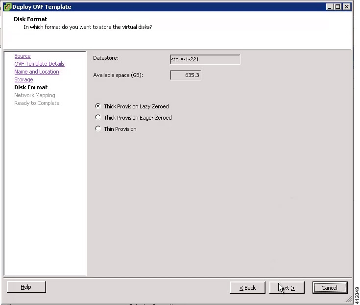
| Step 9 | In the
Disk
Format screen, confirm that the
Thick
Provision Lazy Zeroed radio button is selected and click
Next.
 | ||
| Step 10 | In the
Network
Mapping screen, confirm the source and destination network mappings
and click
Next.
 | ||
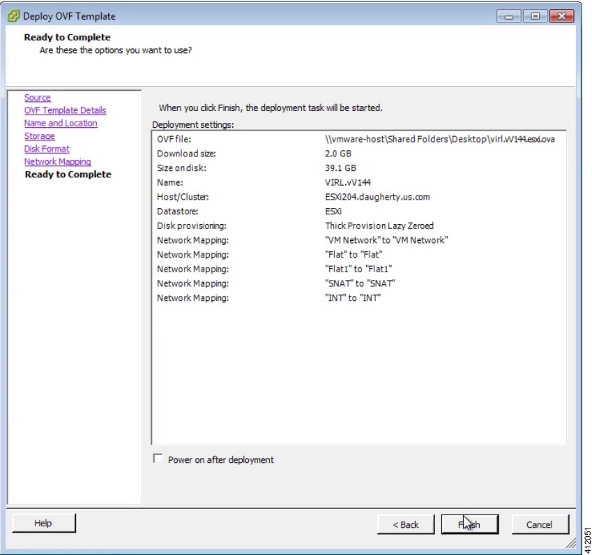
| Step 11 | In the Ready to Complete screen, ensure that the Power On After Deployment check box remains unchecked to allow the virtual machine settings to be updated before it is powered on. | ||
| Step 12 | Click
Finish to start
the OVA deployment.
  |
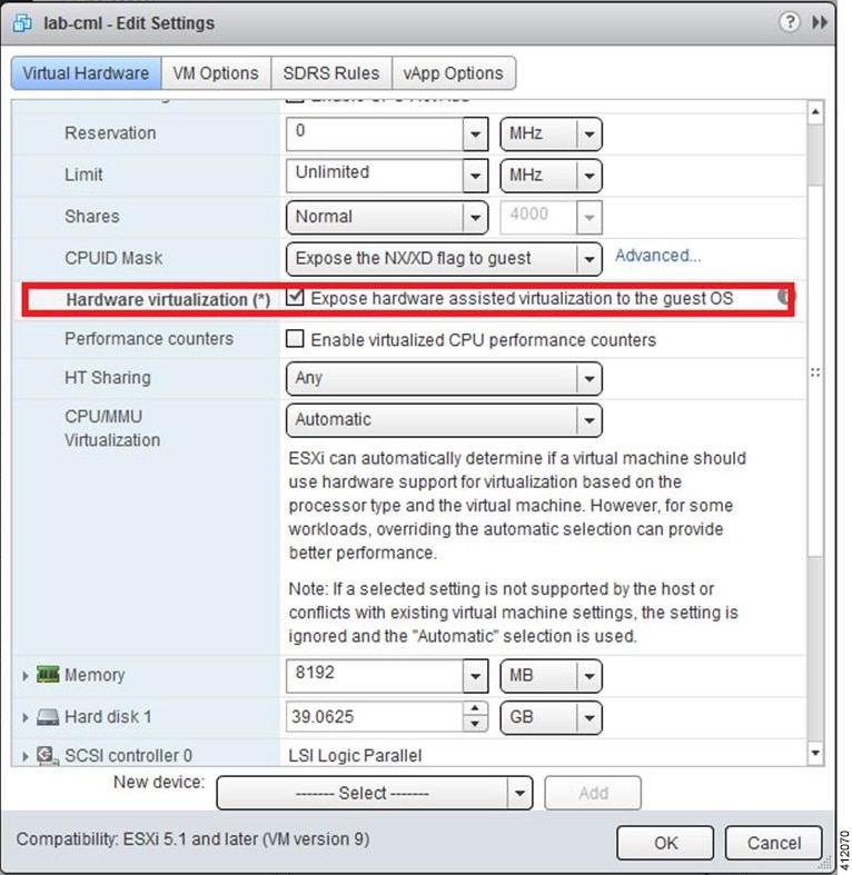
Edit the Virtual Machine Settings
| Step 1 | In the vSphere client, click Edit Virtual Machine Settings. The Virtual Machine Properties dialog box is displayed. |
| Step 2 | Update the
values for
Memory and
CPUs as
required for your environment.
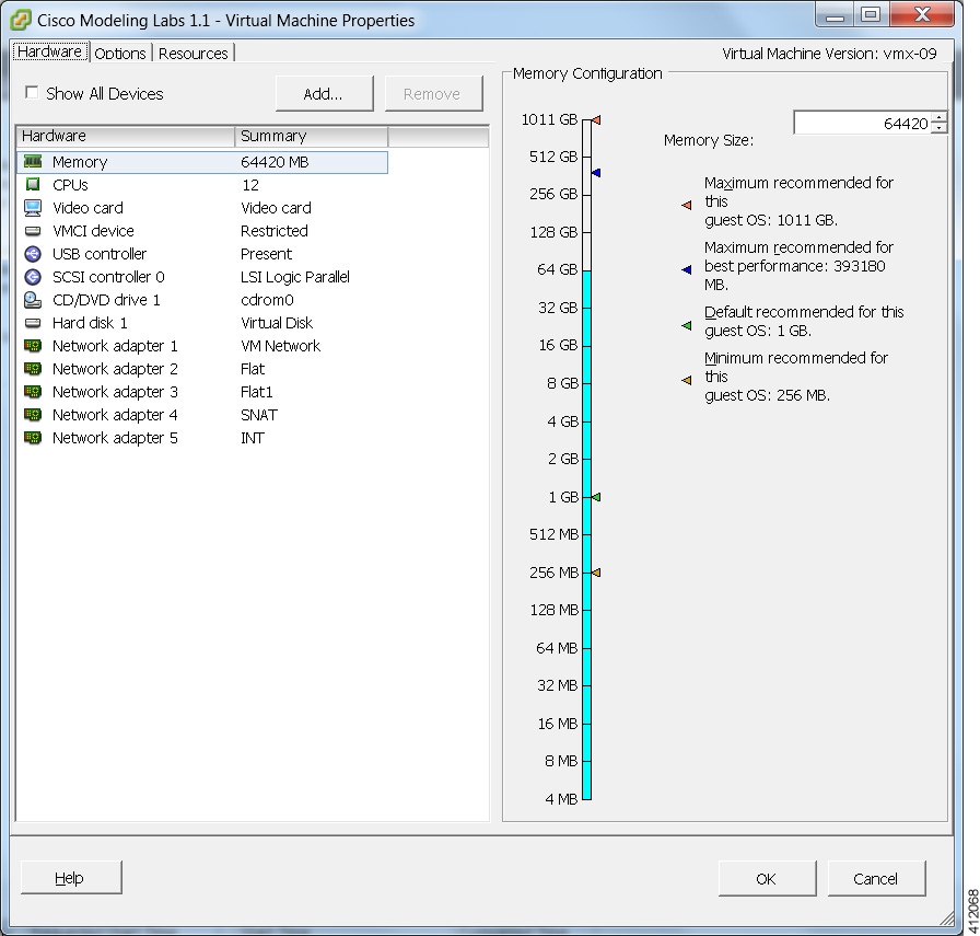 |
| Step 3 | In addition, confirm that the network adapters have been setup correctly. |
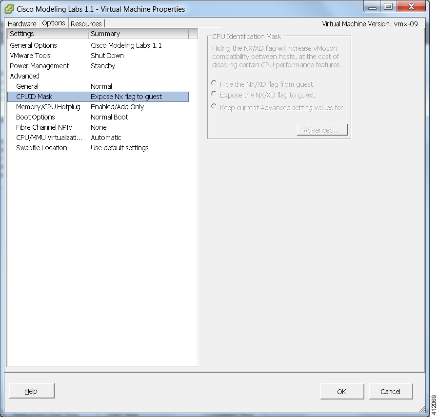
| Step 4 | Under the
Options tab,
ensure that the setting
CPUID Mask
is set to
Expose Nx flag
to guest as shown.
  |
| Step 5 | Click OK to save the changes. |
Customize the Cisco Modeling Labs Server Deployment
Following the software installation, the Cisco Modeling Labs server must be customized for the environment within which it will operate and desired integration with existing lab/test devices. This customization includes setting the following attributes:
- The server's system details
-
The interface configurations associated with external communications (Ethernet1 [Flat], Ethernet2 [Flat1], and Ethernet3 [SNAT].)
-
Application details such as ports associated with the VIRL-services, internal passwords, resource over-commit ratios, and access/download proxy details.
Note | When deploying Cisco Modeling Labs using the OVA-formatted install file, the installed application is preconfigured to use DHCP services to acquire an IP address for the management port, Ethernet0. |
Start the Cisco Modeling Labs Server for the First Time
On initial startup of Cisco Modeling Labs, a virtual console session is started to ascertain the assigned IP address, or to set the static addressing details to the Ethernet0 interface. Complete the following steps to start the Cisco Modeling Labs server for the first time.
| Step 1 | In the vSphere client, click Power On the Virtual Machine. The virtual machine starts up. | |||||||||||||||||||||||||||||||||||||||||||||||||||||||||||||||||||||||||||||||||||||||
| Step 2 | Open a console
window by right-clicking on
Cisco Modeling
Labs 1.2 and choose
Open Console
from the list.
In the
Console window, you can see the virtual machine starting up.
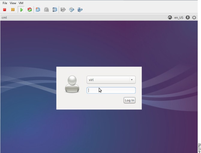
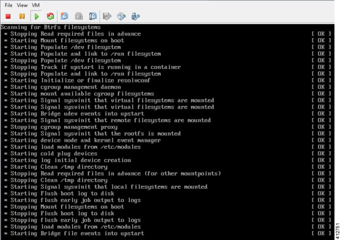 When the virtual machine has started, the login screen is displayed. | |||||||||||||||||||||||||||||||||||||||||||||||||||||||||||||||||||||||||||||||||||||||
| Step 3 | Log in with the
username virl and the password VIRL.
 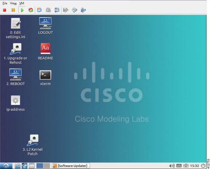 | |||||||||||||||||||||||||||||||||||||||||||||||||||||||||||||||||||||||||||||||||||||||
| Step 4 | On the desktop,
double-click the
xterm icon and
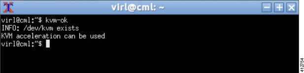
enter the CLI command
kvm-ok in the
terminal window. The response
KVM acceleration can be
used indicates that the nested hypervisor options have
successfully employed.
| |||||||||||||||||||||||||||||||||||||||||||||||||||||||||||||||||||||||||||||||||||||||
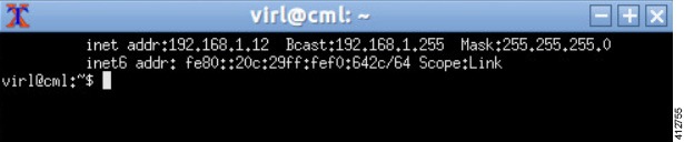
| Step 5 | On the desktop,
double-click the ip_address
icon. This runs a script that detects configuration details applied to the
Ethernet0 interface. If DHCP services are available, the resultant CLI window
will indicate the acquired address assigned to Cisco Modeling Labs’ management
interface. Using a browser, the reported address may be used to open a
User
Workspace Management session to complete the server customization.
Changing Ethernet0 to a static assignment may be done within the
User
Workspace Management interface.
If the
ip-address command returns an IPv4 address, note it down and go to Step 10. If
DHCP is not active on the subnet to which Cisco Modeling Labs’ Ethernet0 is
connected, it is necessary to assign a static IP address before proceeding.
 | |||||||||||||||||||||||||||||||||||||||||||||||||||||||||||||||||||||||||||||||||||||||
| Step 6 | Double-click the xterm icon to open a terminal window and at the command prompt, enter cd /etc/network. | |||||||||||||||||||||||||||||||||||||||||||||||||||||||||||||||||||||||||||||||||||||||
| Step 7 | Enter sudo nano
interfaces to edit the
/etc/network/interfaces configuration file.
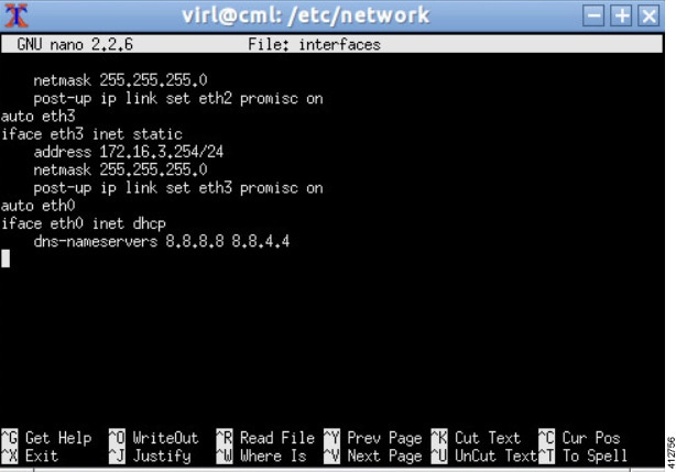 | |||||||||||||||||||||||||||||||||||||||||||||||||||||||||||||||||||||||||||||||||||||||
| Step 8 | Scroll through
the file to the configuration associated with Ethernet0 and make the following
changes:
| |||||||||||||||||||||||||||||||||||||||||||||||||||||||||||||||||||||||||||||||||||||||
| Step 9 | Reboot the virtual machine using the sudo reboot now command. | |||||||||||||||||||||||||||||||||||||||||||||||||||||||||||||||||||||||||||||||||||||||
| Step 10 | Once the virtual
machine completes the reboot cycle, establish a browser session to the Cisco
Modeling Labs server’s management interface (either the DHCP acquired address
noted earlier, or the static address added to the /etc/network/interfaces
file.)
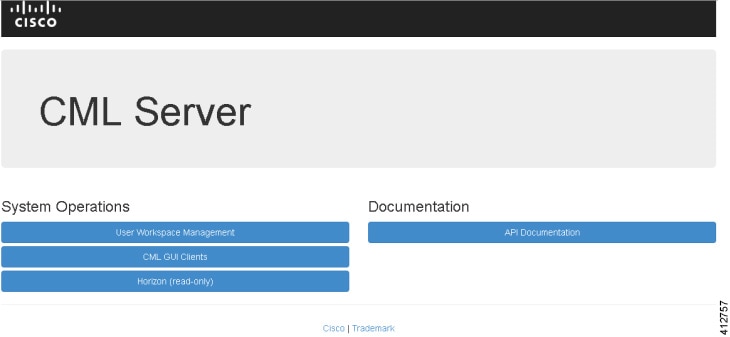 | |||||||||||||||||||||||||||||||||||||||||||||||||||||||||||||||||||||||||||||||||||||||
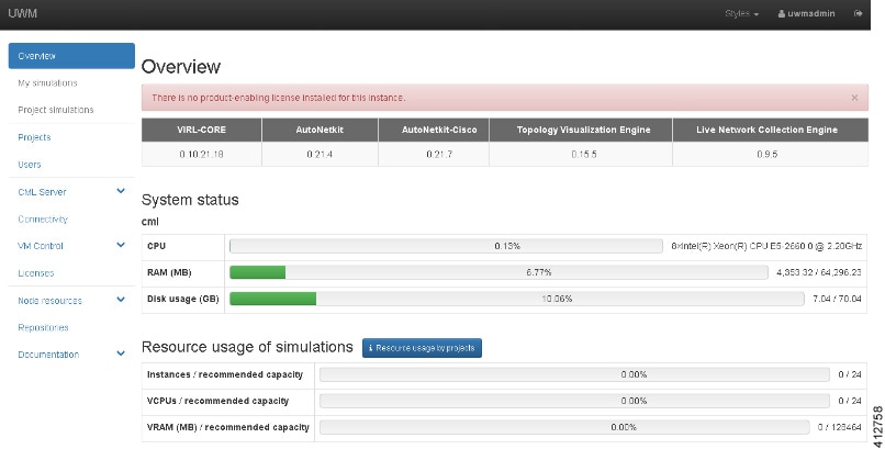
| Step 11 | Click the
User
Workspace Management interface link. Login with the default
credentials (username= uwmadmin, password=password). The
User
Workspace Management Overview page is displayed.
 | |||||||||||||||||||||||||||||||||||||||||||||||||||||||||||||||||||||||||||||||||||||||
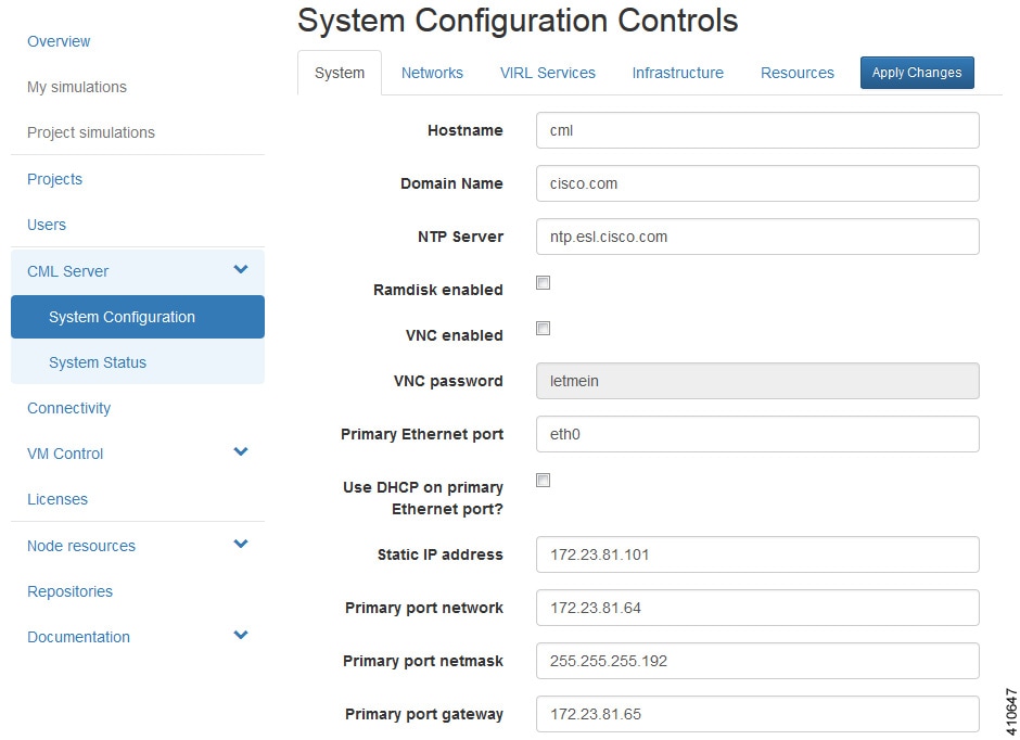
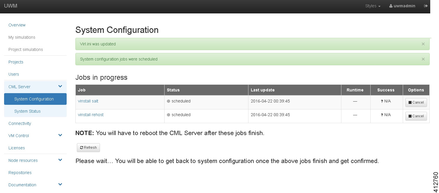
| Step 12 | From the options
on the left, expand the
CML Server
option and select
System
Configuration. Click
System to
set the system management details.
| |||||||||||||||||||||||||||||||||||||||||||||||||||||||||||||||||||||||||||||||||||||||
| Step 13 | Click
Networks
to configure the other interfaces for external communications.
| |||||||||||||||||||||||||||||||||||||||||||||||||||||||||||||||||||||||||||||||||||||||
| Step 14 | Click
VIRL
Services to configure the port numbers for VIRL services.
| |||||||||||||||||||||||||||||||||||||||||||||||||||||||||||||||||||||||||||||||||||||||
| Step 15 | Click
Infrastructure to configure the other interfaces for
external communications.
| |||||||||||||||||||||||||||||||||||||||||||||||||||||||||||||||||||||||||||||||||||||||
| Step 16 | Click
Resources
to configure the other interfaces for external communications to meet
integration requirements.
| |||||||||||||||||||||||||||||||||||||||||||||||||||||||||||||||||||||||||||||||||||||||
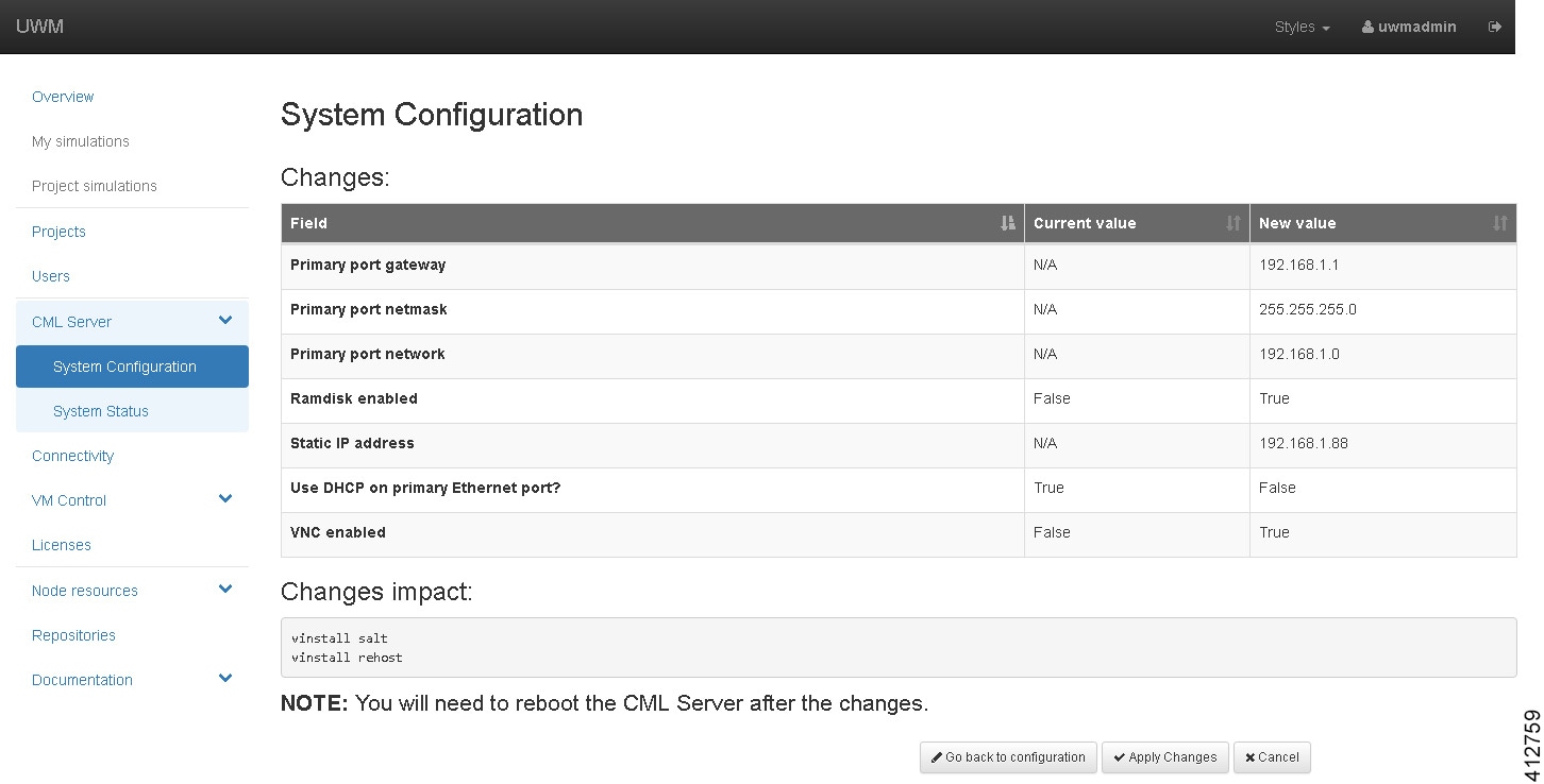
| Step 17 | With all
configuration options set, click
Apply
Changes. A summary of the changes is presented, showing the previous
parameters settings and the new values being applied. Having confirmed that all
changes are correct, click
Apply
Changes at the bottom of the page.
     | |||||||||||||||||||||||||||||||||||||||||||||||||||||||||||||||||||||||||||||||||||||||
| Step 18 | Return to the Cisco Modeling Labs virtual machine console and open an xterm window. Initiate a system reboot with the sudo reboot now command. Alternatively, double-click on the 2. REBOOT icon on the desktop. When the system reboot has completed, return to the User Workspace Management interface to confirm the custom settings. |
(Optional) Configure Static IP
In accordance with best practices and to account for a possible lack of DHCP services, it is recommended that the eth0 interface be configured with a static IP address, as follows:
| Step 1 | Start the
virtual machine and log in using the username virl and the password VIRL.
| ||
| Step 2 | Click the xterm icon to open a terminal window. | ||
| Step 3 | Change to the network interfaces configuration directory: cd /etc/network | ||
| Step 4 | Open the interfaces configuration file for editing: sudo nano interfaces | ||
| Step 5 | Change the eth0 addressing method to static: iface eth0 inet static | ||
| Step 6 | Provide the static IP address: address n.n.n.n | ||
| Step 7 | Provide the static IP address netmask: netmask mmm.mmm.mmm.mmm | ||
| Step 8 | Provide the
default IP gateway address:
gateway
g.g.g.g
| ||
| Step 9 | Provide valid reachable DNS name-server addresses: dns-nameservers a.a.a.a b.b.b.b | ||
| Step 10 | Enter Ctrl-X to exit. | ||
| Step 11 | Enter Y and Enter to confirm saving the interfaces file and exit. | ||
| Step 12 | Enter sudo reboot now to reboot the virtual machine in preparation for the remaining installation steps. |
Determine License Key Requirements
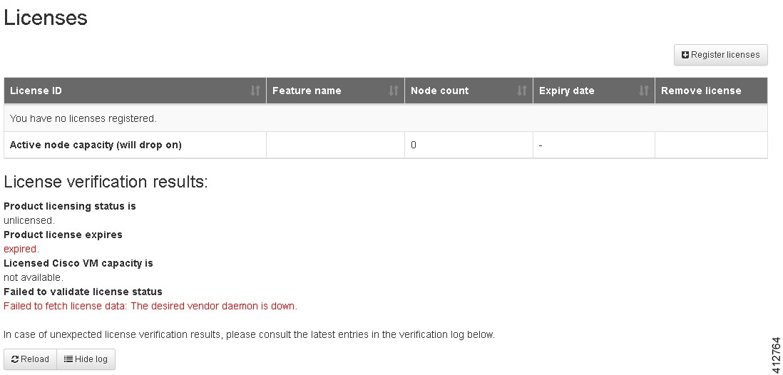
Returning to the
User Workplace Management interface shows the server’s current licensing
status; the red banner indicates that there is no product licensing in place.
To license the Cisco Modeling Labs server, complete the following steps:
| Step 1 | In the left
pane, click
Licenses.
The
Licenses page is displayed.
 | ||||||||
| Step 2 | In the Licenses page, click Register Licenses. | ||||||||
| Step 3 | Record the
Host Name and
Mac Address for
license key registration.
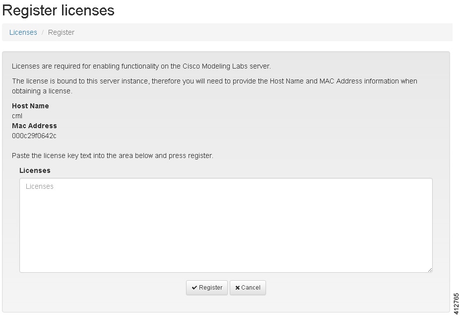 Use this information when completing the Register Claim Certificates instructions in the eDelivery Order Notification email to request your license key for use with the Cisco Modeling Labs server.
You will receive your license key as an attachment via an email. | ||||||||
| Step 4 | Open the attachment in a text editor and copy all of the contents. | ||||||||
| Step 5 | Return to the
Register
Licenses
page and paste the details into the
Licenses
text area.
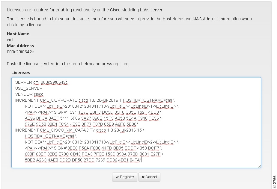 | ||||||||
| Step 6 | Click
Register to
register the license key.
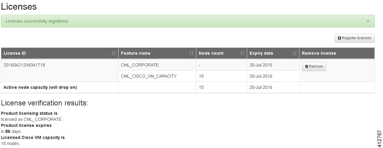 | ||||||||
| Step 7 | Repeat Steps 4 – 6 for each license file received from the registration process. Verify that the Licenses page correctly reports the applied node count and expiration dates. | ||||||||
| Step 8 | Click Log Out to exit the User Workspace Management interface. |
 Feedback