- Prepare for an OVA File Installation
- Download the Cisco Modeling Labs OVA File
- Configure Security and Network Settings
- Deploy the Cisco Modeling Labs OVA
- Edit the Virtual Machine Settings
- Start the Cisco Modeling Labs Server for the First Time
- (Optional) Configure Static IP
- Determine License Key Requirements
Cisco Modeling Labs OVA Installation
Prepare for an OVA File Installation
There is a number of key prerequisites that must be in place in order to successfully install Cisco Modeling Labs using an OVA file.
These prerequisites are:
-
The host must support Intel VT-x/EPT virtualization extensions, and these extensions must be enabled in the BIOS.
-
The target disk must be at least 250 GB.
-
For installations to a VM, the following hypervisors are supported: -
VMware vSphere ESXi 5.1 U2 (Build 1483097) or later.
-
VMware vSphere ESXi 5.5 U1 (Build 1623387) or later.
-
VMware vSphere ESXi 6.0 (Build 2494585).

Note
Additionally, you must verify that you are using vSphere Client v5.5 Update 2 (Build 1993072) or later before deploying Cisco Modeling Labs. Failure to use this minimum version will result in a failed deployment that returns an error stating that nested virtualization is not supported.
Note
Oracle VirtualBox VM is not supported due to its lack of support for nested virtual machines. -
Note | Depending on network speed and target platform performance, an installation can take between 30 and 60 minutes. |
Download the Cisco Modeling Labs OVA File
You must download the Cisco Modeling Labs OVA file using the link provided in your purchase confirmation email.
The OVA files are large (~4 GB), so rather than HTTP downloads using a web browser, the use of a download manager for Mac or Windows is recommended.
An MD5 hash sum for the OVA file is provided along with the download link on the download website. You must calculate and verify that the hash sum of the downloaded OVA file matches the source file:
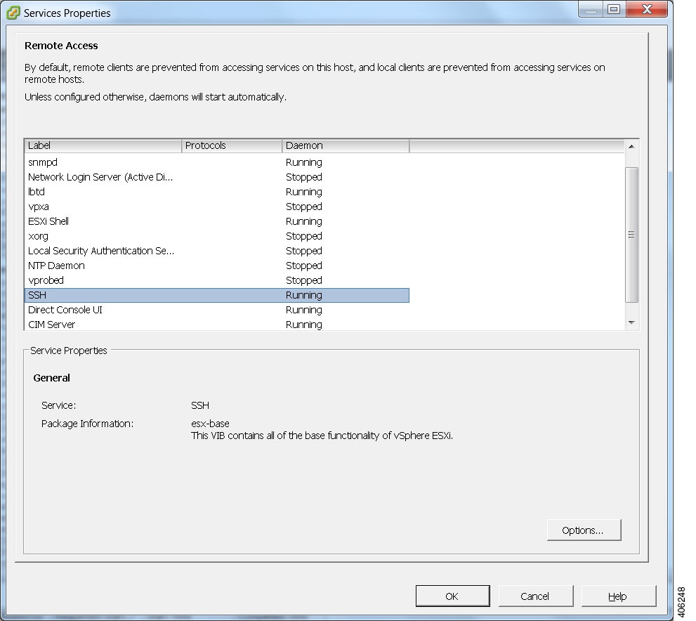
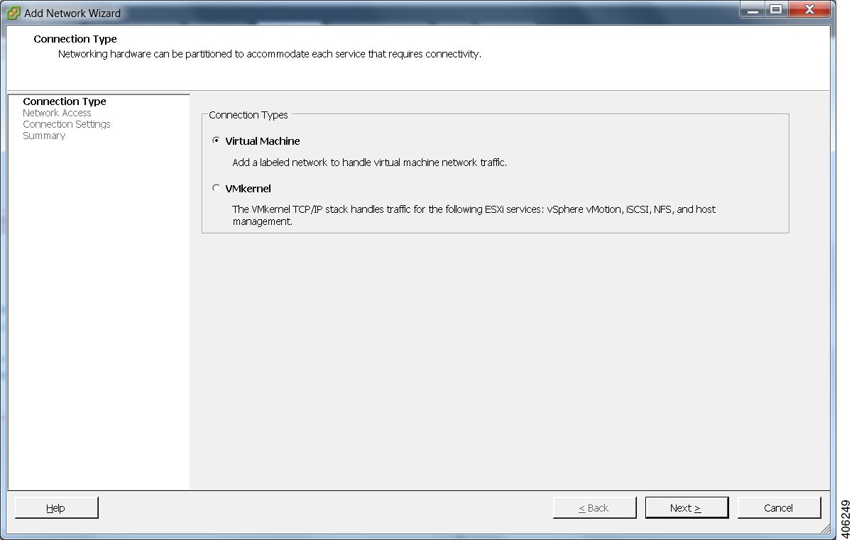
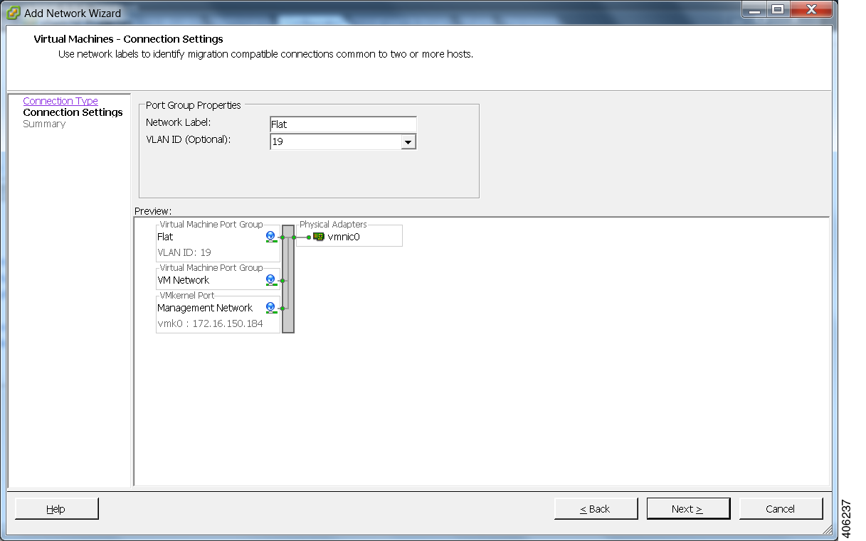
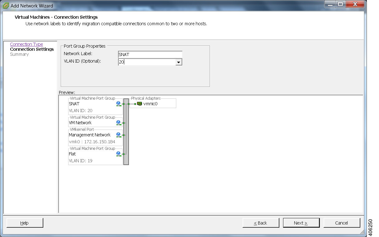
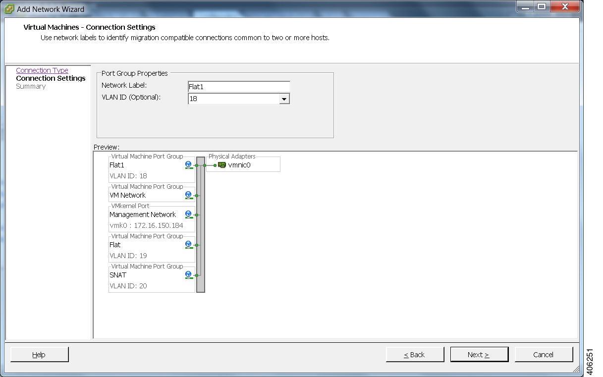
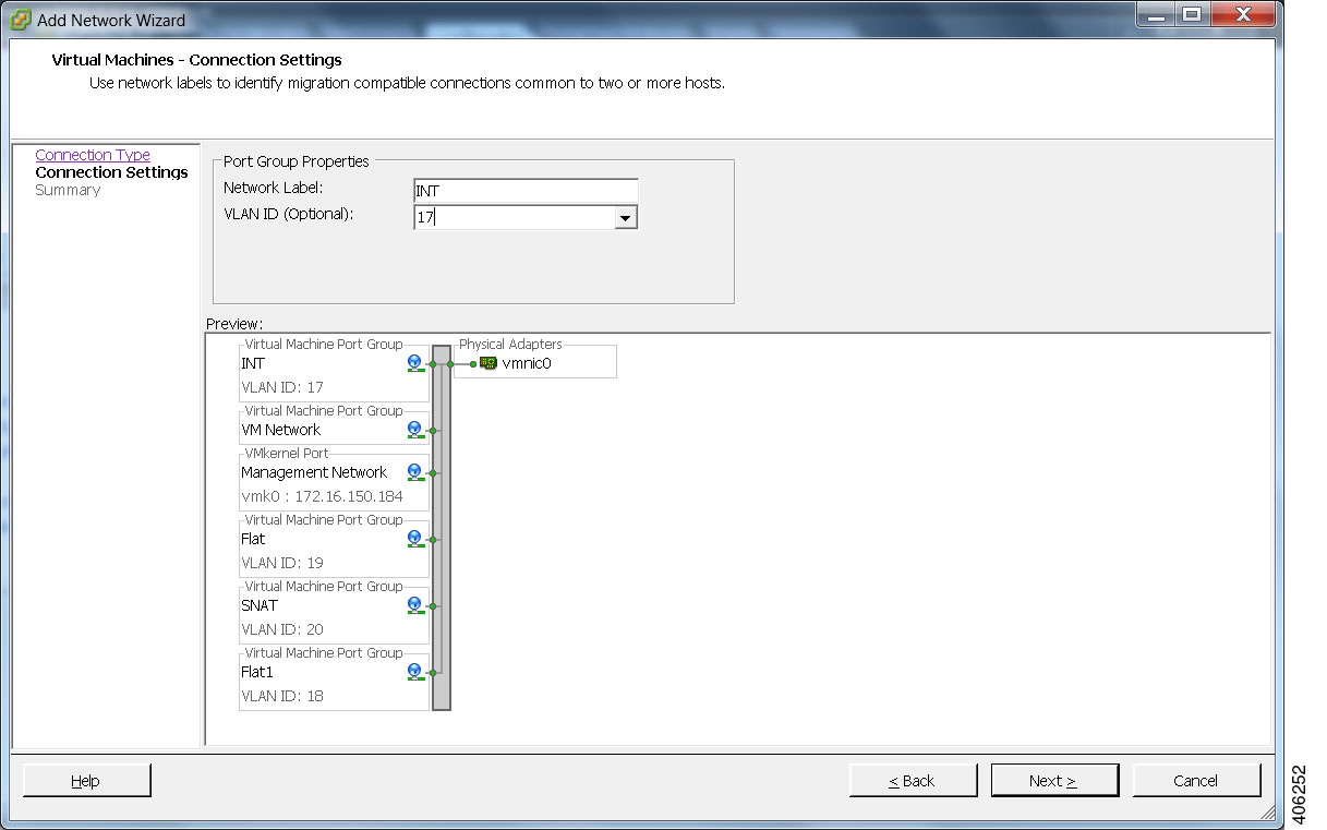
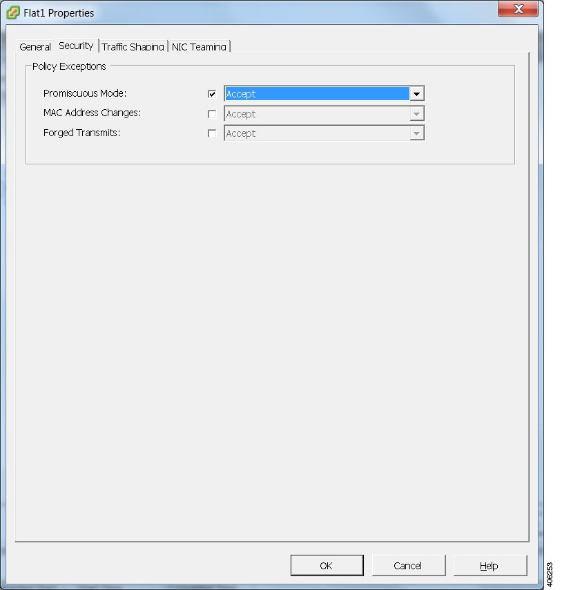
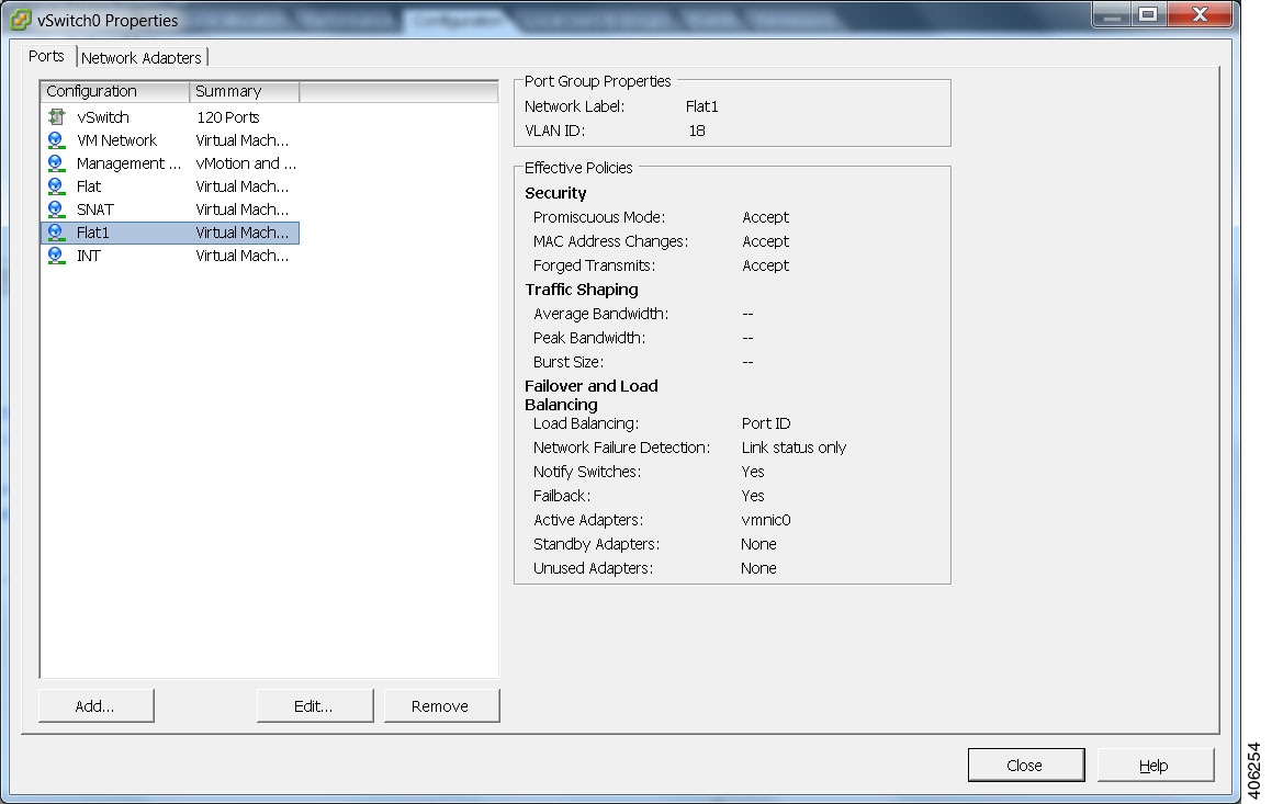
Configure Security and Network Settings
Note | You must enable Intel VT in the BIOS for Cisco Modeling Labs to operate correctly. |
The Cisco Modeling Labs virtual machine requires connections to five unique virtual network port groups, the first of which is for management and is site unique. It is, by default, VM Network. The other four port-groups areFlat, Flat1, SNAT, and INT. They are used by Cisco Modeling Labs for external Layer 2 and Layer 3 connectivity and are created as described in this section.
- Ensure that you have met the requirements as specified in the section Cisco Modeling Labs Server Requirements.
- Ensure that you have administrator access to the VMware ESXi server in which you plan to deploy the Cisco Modeling Labs OVA in order to enable nested virtualization.
Deploy the Cisco Modeling Labs OVA
| Step 1 | To install the OVA, log in to the VMware ESXi server. | ||
| Step 2 | From the vSphere
Client menu, choose
.
 | ||
| Step 3 | Click Next. | ||
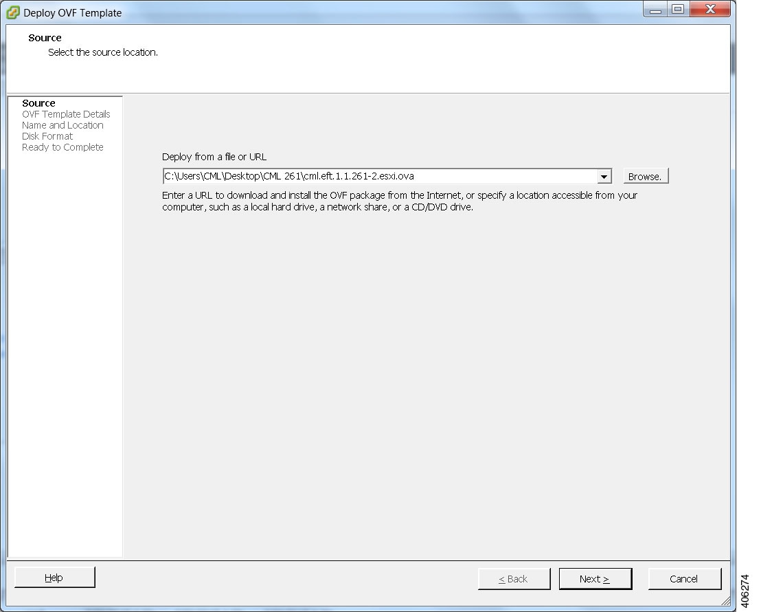
| Step 4 | In the Source screen, click Browse to navigate to the OVA package. | ||
| Step 5 | In the dialog box displayed, click Open. | ||
| Step 6 | Click
Next to review
the OVA details.
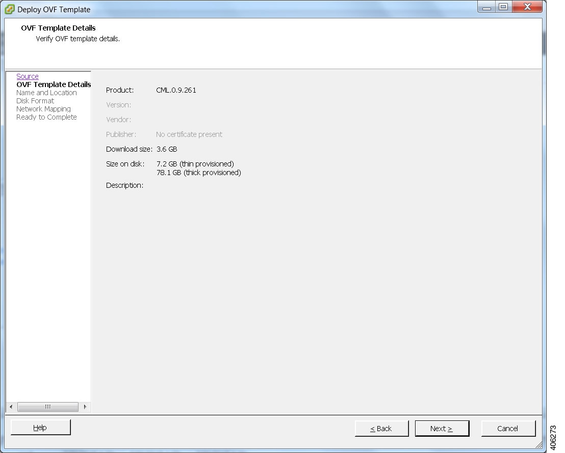 | ||
| Step 7 | Click Next. | ||
| Step 8 | In the
Name and
Location screen, confirm or provide a new name for the virtual
machine, for example,
Cisco Modeling
Labs, and click
Next.
 | ||
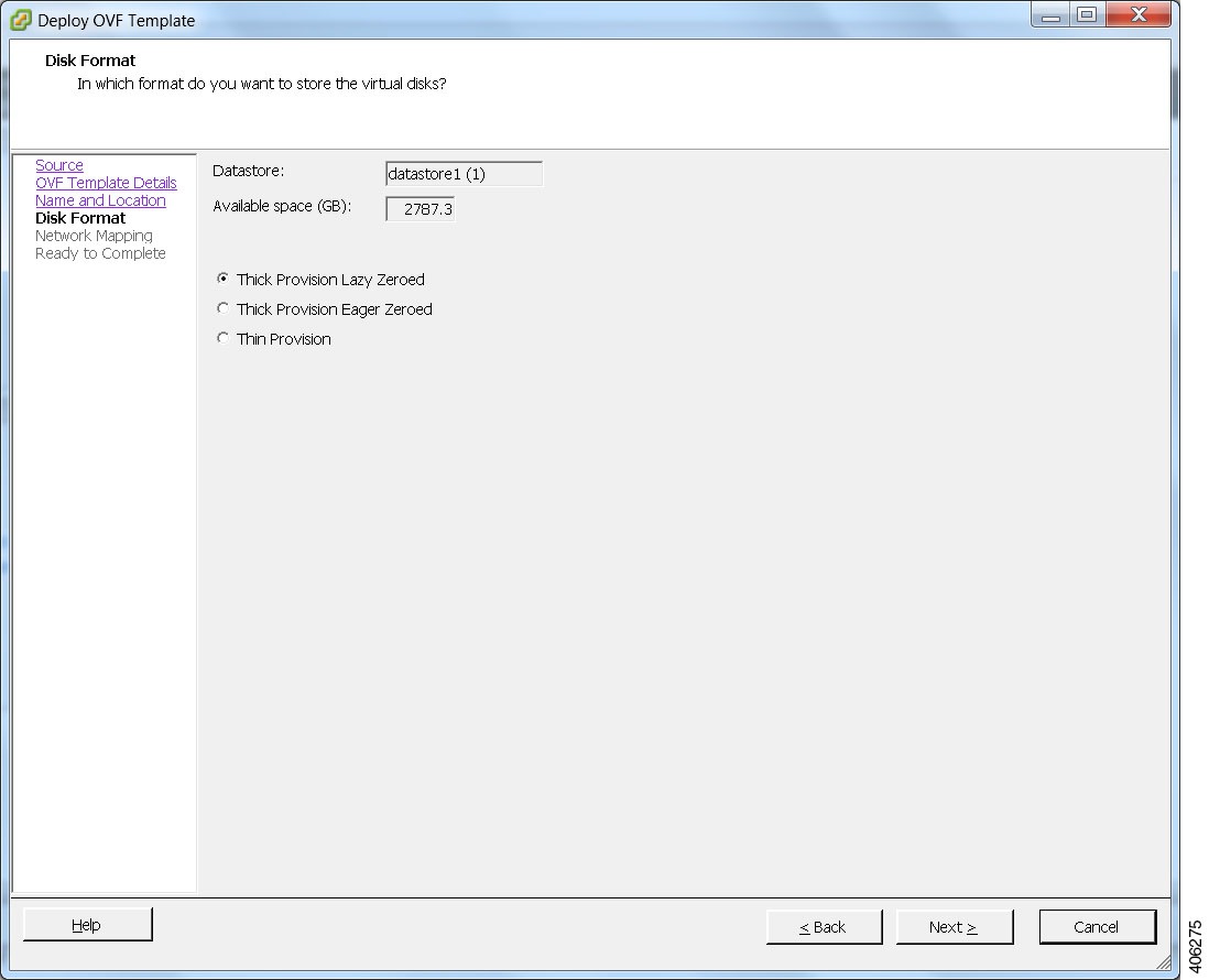
| Step 9 | In the
Disk
Format screen, confirm that the
Thick
Provision Lazy Zeroed radio button is selected and click
Next.
 | ||
| Step 10 | In the
Network
Mapping screen, confirm the source and destination network mappings
and click
Next.
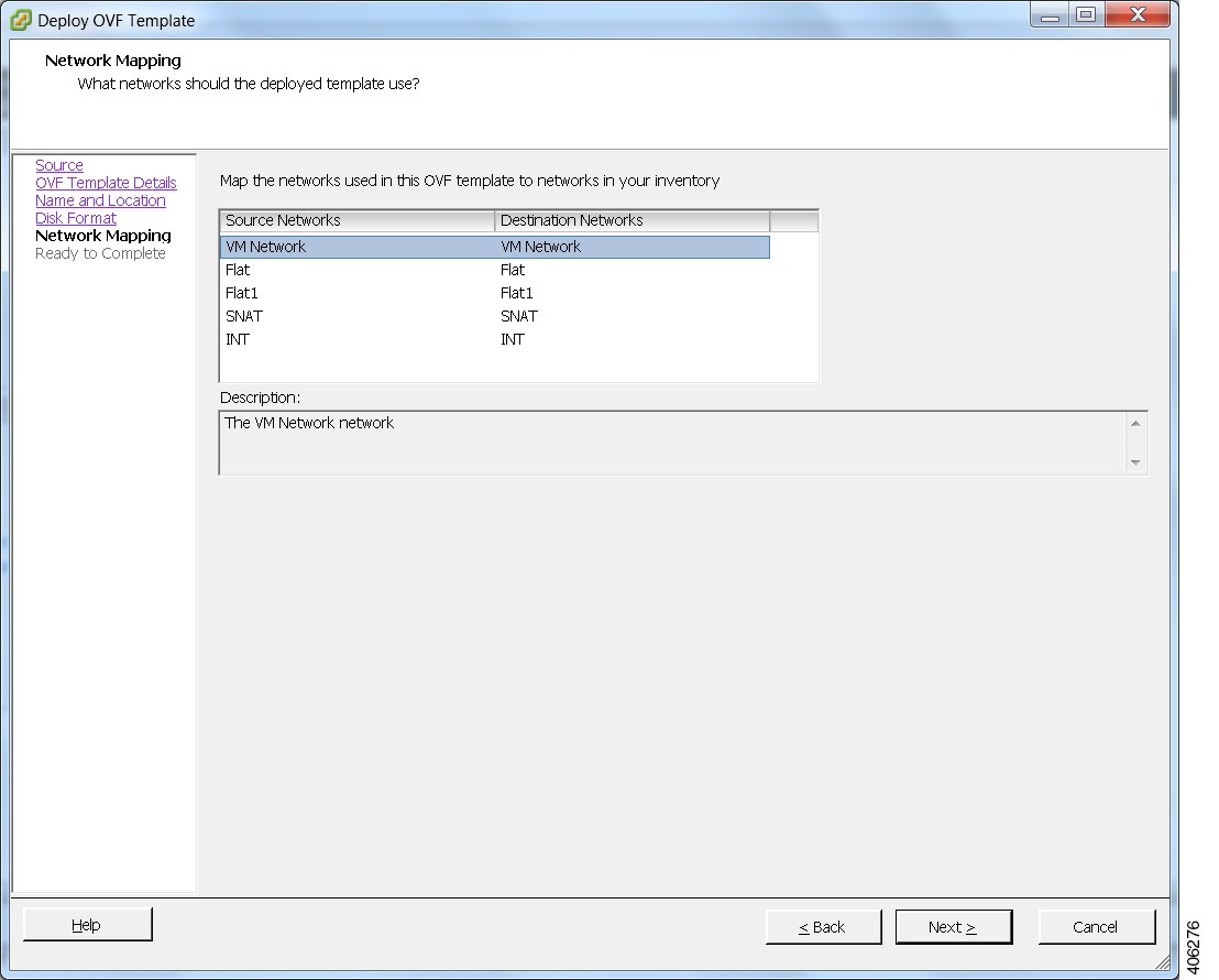 | ||
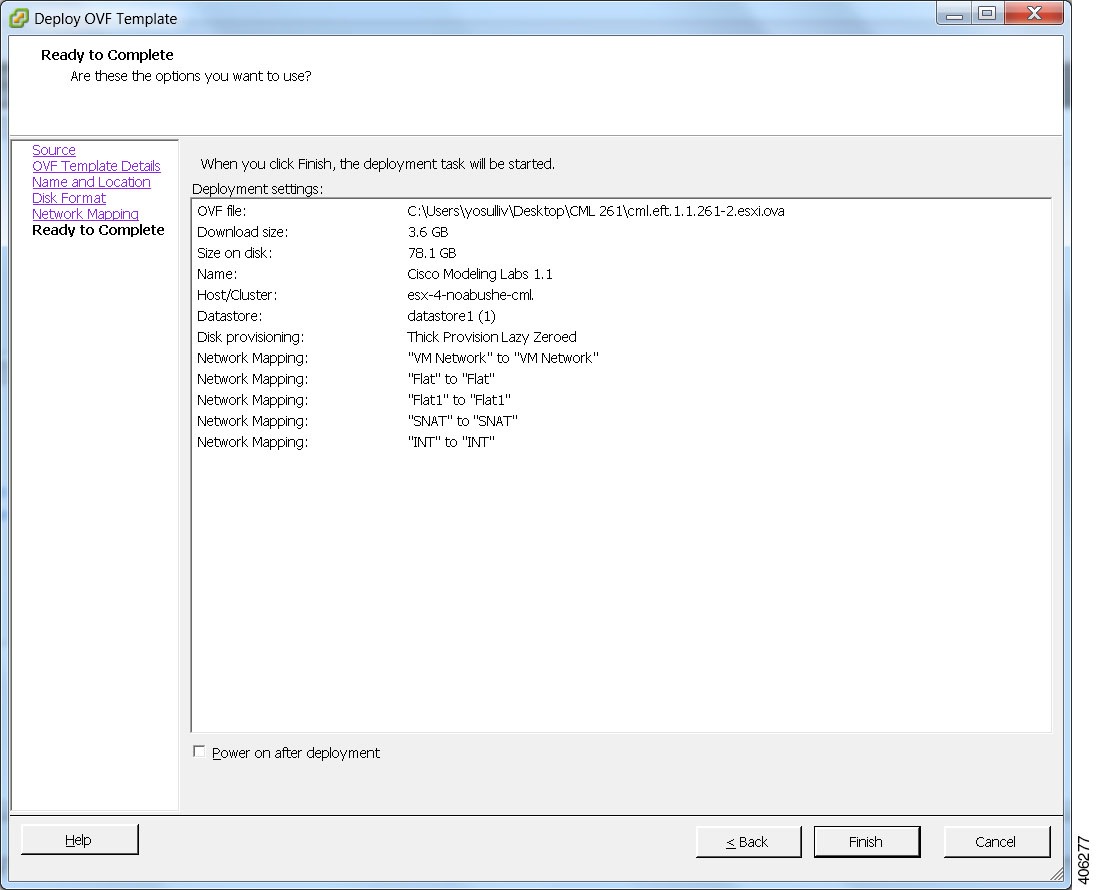
| Step 11 | In the Ready to Complete screen, ensure that the Power On After Deployment check box remains unchecked to allow the virtual machine settings to be updated before it is powered on. | ||
| Step 12 | Click
Finish to start
the OVA deployment.
  |
Edit the Virtual Machine Settings
| Step 1 | In the vSphere client, click Edit Virtual Machine Settings. The Virtual Machine Properties dialog box is displayed. |
| Step 2 | Update the
values for
Memory and
CPUs as
required for your environment.
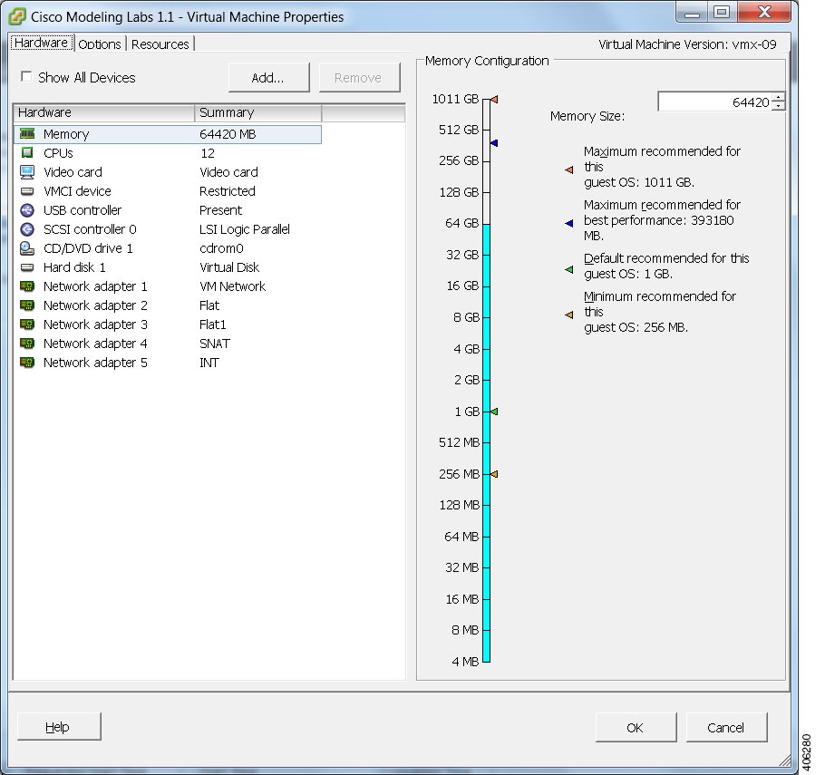 |
| Step 3 | In addition, confirm that the network adapters have been setup correctly. |
| Step 4 | Under the
Options tab,
ensure that the setting
CPUID Mask
is set to
Expose Nx flag
to guest as shown.
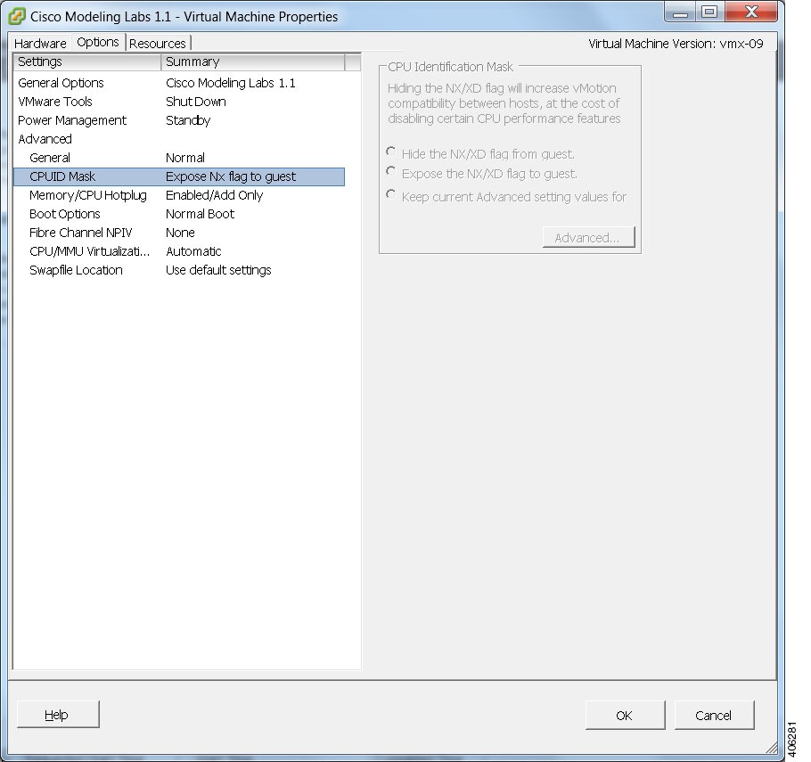  |
| Step 5 | Click OK to save the changes. |
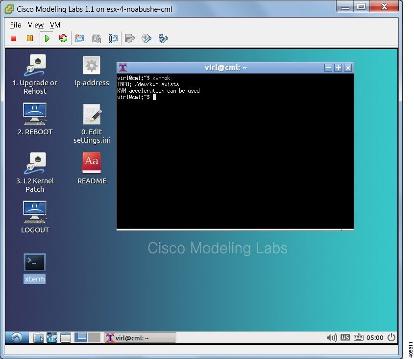
Start the Cisco Modeling Labs Server for the First Time
| Step 1 | In the vSphere client, click Power On the Virtual Machine. The virtual machine starts up. | ||
| Step 2 | Open a console
window by right-clicking on
Cisco Modeling
Labs 1.1 and choose
Open Console
from the list.
In the
Console window you can see the virtual machine starting up.
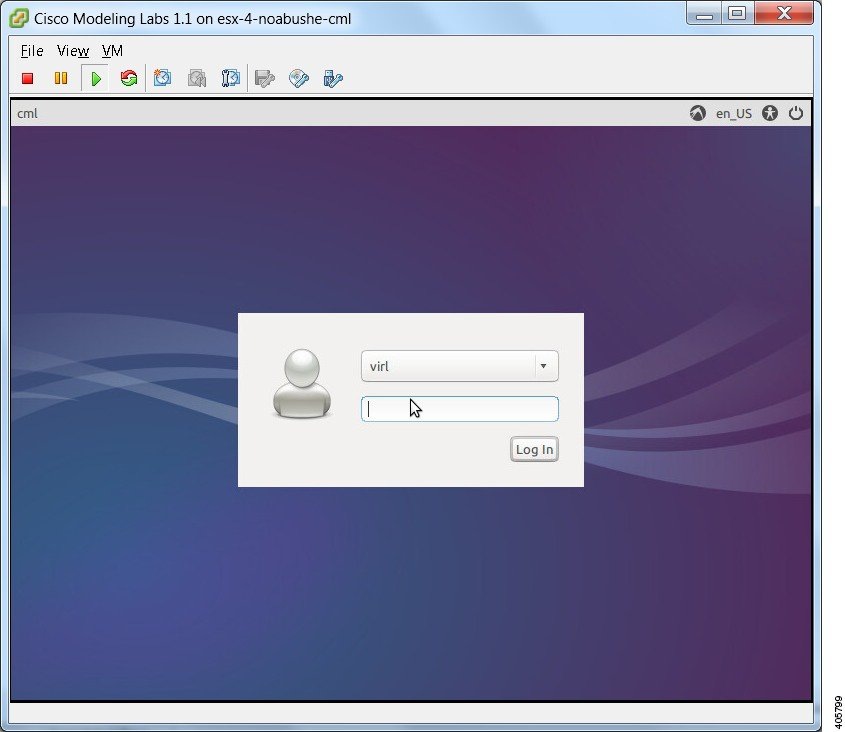
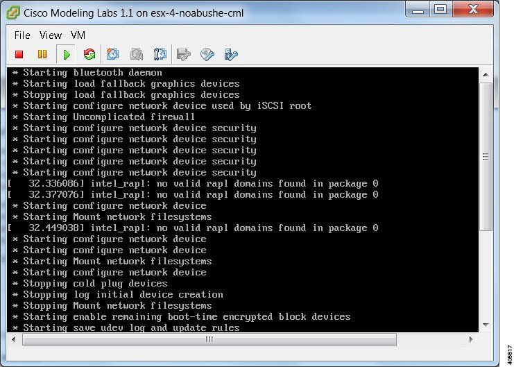 When the virtual machine has started, the login screen is displayed. | ||
| Step 3 | Log in with the
username virl and the password VIRL.
 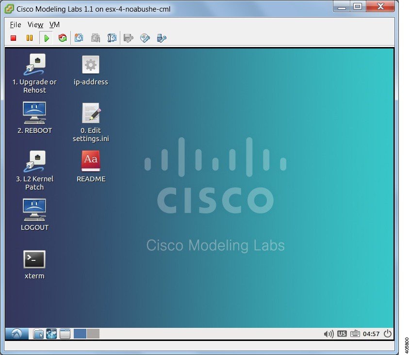 | ||
| Step 4 | On the desktop,
click the
xterm icon and
enter the CLI command
kvm-ok. To
ensure that the installation worked correctly, confirm that you received the
statement
acceleration can be
used, indicating that the images will work.
 | ||
| Step 5 | Double-click the 0. Edit settings.ini file icon on the desktop. | ||
| Step 6 | Scroll down the
file and update the following:
| ||
| Step 7 | On the desktop, click the 1. Upgrade or Rehost icon to start a standard installation process. | ||
| Step 8 | When completed, click the 2. REBOOT icon to reboot the virtual machine. | ||
| Step 9 | Log in with the username virl and the password VIRL. | ||
| Step 10 | Enter the
command
ifconfig
eth0 to view the IP address assigned.
You will use this IP address to access the User Workspace Management interface. |
(Optional) Configure Static IP
Where there is no DHCP addressing facility on the subnet to which the Cisco Modeling Labs virtual machine is connected via eth0, it is necessary to assign a static IP address before proceeding.
This section describes the configuration steps to use when Static IP addressing is required. However, if DHCP is being used to configure the eth0 IP address, you may skip this section.
| Step 1 | Start the
virtual machine and log in using the username virl and the password VIRL.
| ||
| Step 2 | Click the xterm icon to open a terminal window. | ||
| Step 3 | Change to the network interfaces configuration directory: cd /etc/network | ||
| Step 4 | Open the interfaces configuration file for editing: sudo nano interfaces | ||
| Step 5 | Change the eth0 addressing method to static: iface eth0 inet static | ||
| Step 6 | Provide the static IP address: address n.n.n.n | ||
| Step 7 | Provide the static IP address netmask: netmask mmm.mmm.mmm.mmm | ||
| Step 8 | Provide the default IP gateway address: gateway g.g.g.g | ||
| Step 9 | Provide valid reachable DNS name-server addresses: dns-nameservers a.a.a.a b.b.b.b | ||
| Step 10 | Enter Ctrl-X to exit. | ||
| Step 11 | Enter Y and Enter to confirm saving the interfaces file and exit. | ||
| Step 12 | Enter sudo reboot now to reboot the virtual machine in preparation for the remaining installation steps. |
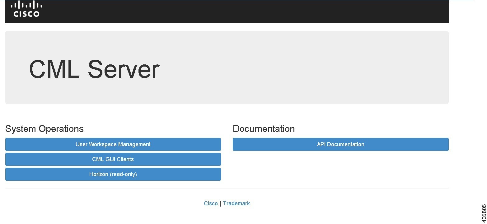
Determine License Key Requirements
| Step 1 | In a web browser, use the IP address or hostname of your Cisco
Modeling Labs server to access the
CML Server interface, in the format
http://<IP address | hostname>.
| ||||||||
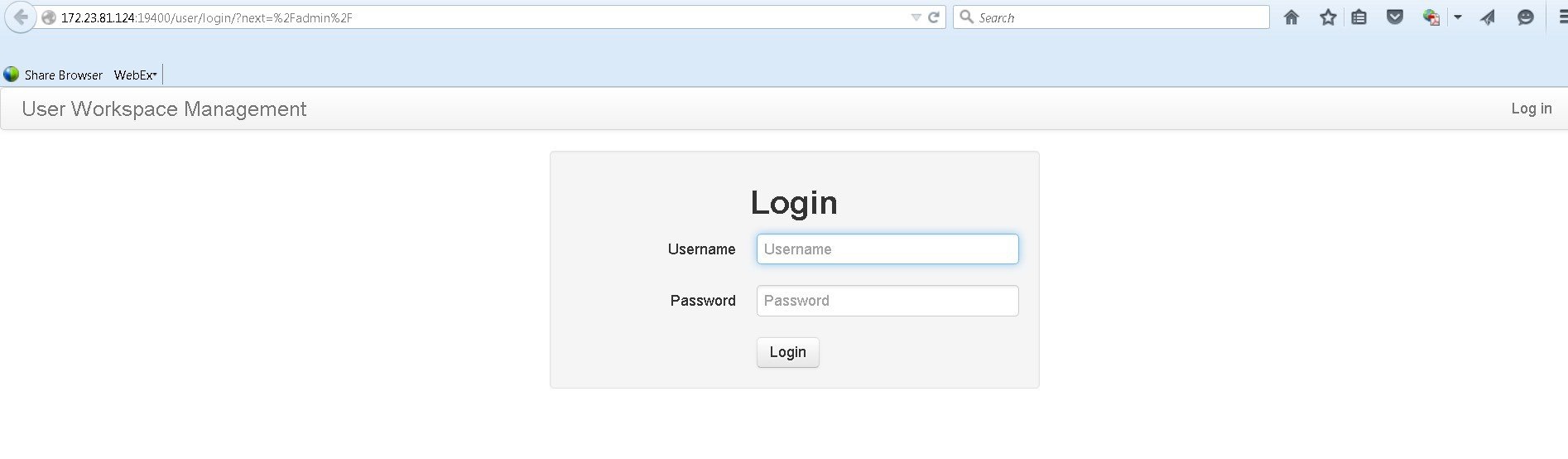
| Step 2 | Click
User Workspace
Management and log in to the interface using the username
uwmadmin and
the password
password and
switch to
Admin mode.
 | ||||||||
| Step 3 | In the left pane, click Licenses. | ||||||||
| Step 4 | In the Licenses page, click Register Licenses. | ||||||||
| Step 5 | Record the
Host Name and
Mac Address for
license key registration.
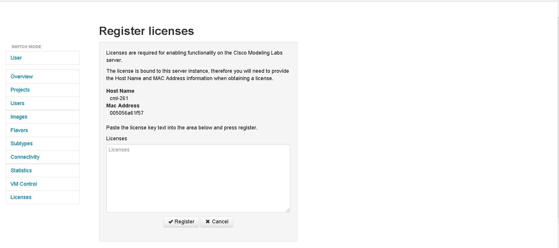 Use this information when completing the Register Claim Certificates instructions in the eDelivery Order Notification email to request your license key for use with the Cisco Modeling Labs server.
You will receive your license key as an attachment via an email. | ||||||||
| Step 6 | Open the attachment in a text editor and copy all the details. | ||||||||
| Step 7 | Return to the Register Licenses page. | ||||||||
| Step 8 | Repeat Step 1 and Step 2, and paste the details into the Licenses text area. | ||||||||
| Step 9 | Click
Register to
register the license key.
| ||||||||
| Step 10 | Click Log Out to exit the User Workspace Management interface. |
 Feedback