Cisco Modeling Labs Corporate Edition System Administrator Installation Guide, Release 1.1
Bias-Free Language
The documentation set for this product strives to use bias-free language. For the purposes of this documentation set, bias-free is defined as language that does not imply discrimination based on age, disability, gender, racial identity, ethnic identity, sexual orientation, socioeconomic status, and intersectionality. Exceptions may be present in the documentation due to language that is hardcoded in the user interfaces of the product software, language used based on RFP documentation, or language that is used by a referenced third-party product. Learn more about how Cisco is using Inclusive Language.
- Updated:
- September 29, 2015
Chapter: User Workspace Management
- Access the User Workspace Management Interface
- Admin Mode Versus User Mode
- Manage Projects
- Manage Users
- Manage VM Images
- Manage Virtual Machine Flavors
- Manage Subtypes
- System Statistics
- Connectivity
- Using the VM Control Tool
- Manage Cisco Modeling Labs Licenses
- Stop Active Sessions in the User Workspace Management Interface
User Workspace Management
Access the User Workspace Management Interface
After you have started the Cisco Modeling Labs server, you can access the User Workspace Management interface to manage user accounts, projects, licenses, and virtual machine images on the Cisco Modeling Labs server.
To access the User Workspace Management interface, complete the following steps:
| Step 1 | In the Cisco Modeling Labs server, retrieve the IP address of the VM using the command ifconfig eth0. | ||
| Step 2 | In a web browser, enter the retrieved IP address or hostname in
the format,
http://<IP address |
hostname>.
The
CML Server main menu page is displayed.
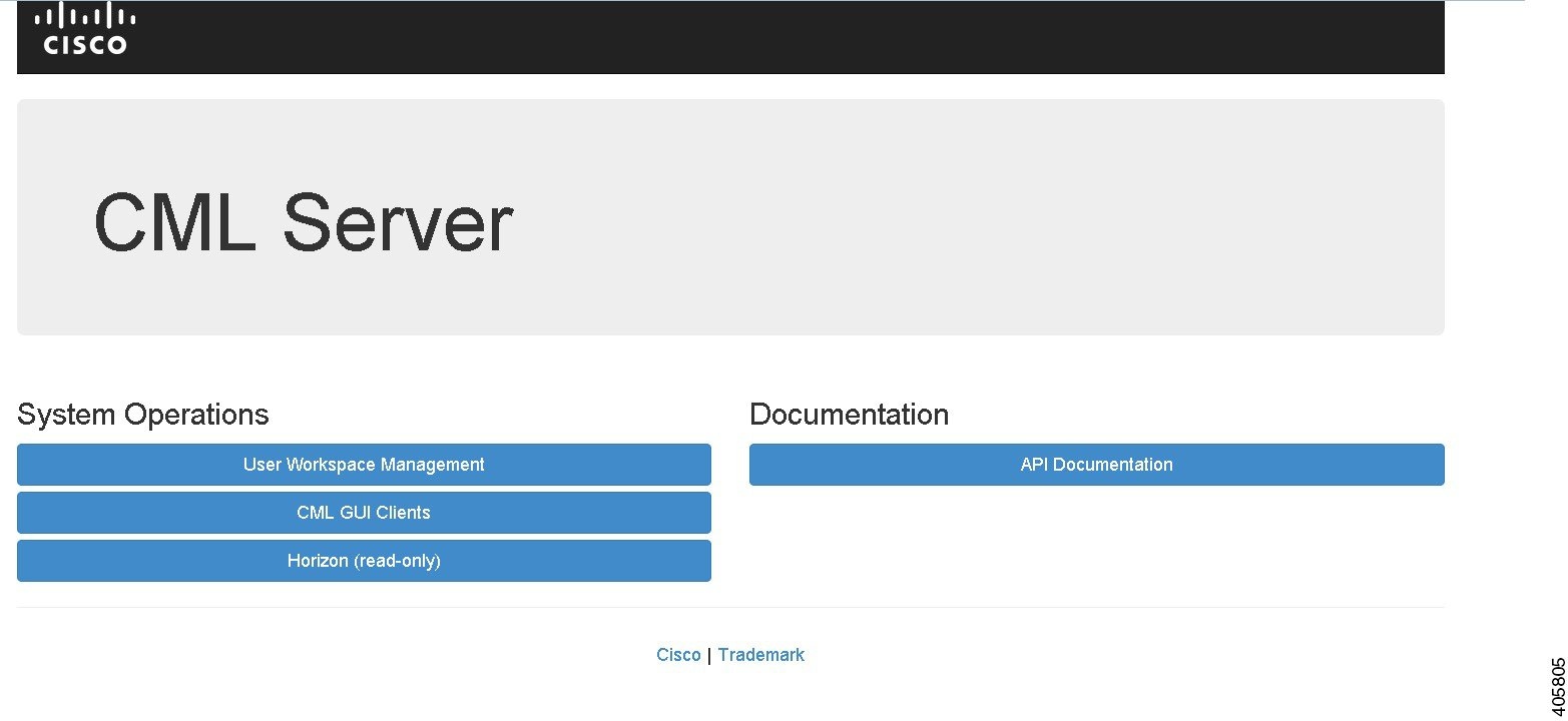 | ||
| Step 3 | Click User Workspace Management to access the User Workspace Management interface. | ||
| Step 4 | Log in to the
User Workspace Management interface using the
username uwmadmin and the password password.
| ||
| Step 5 | To change to
admin mode, click
Admin under the
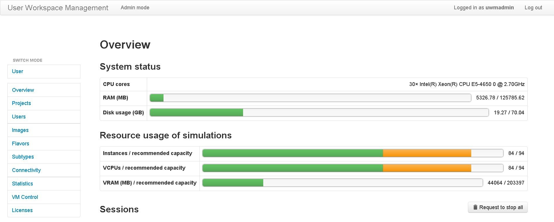
Switch Mode section. An overview of the current system-usage statistics for all
the active simulations is displayed.
|
Change the Password for the uwmadmin Account
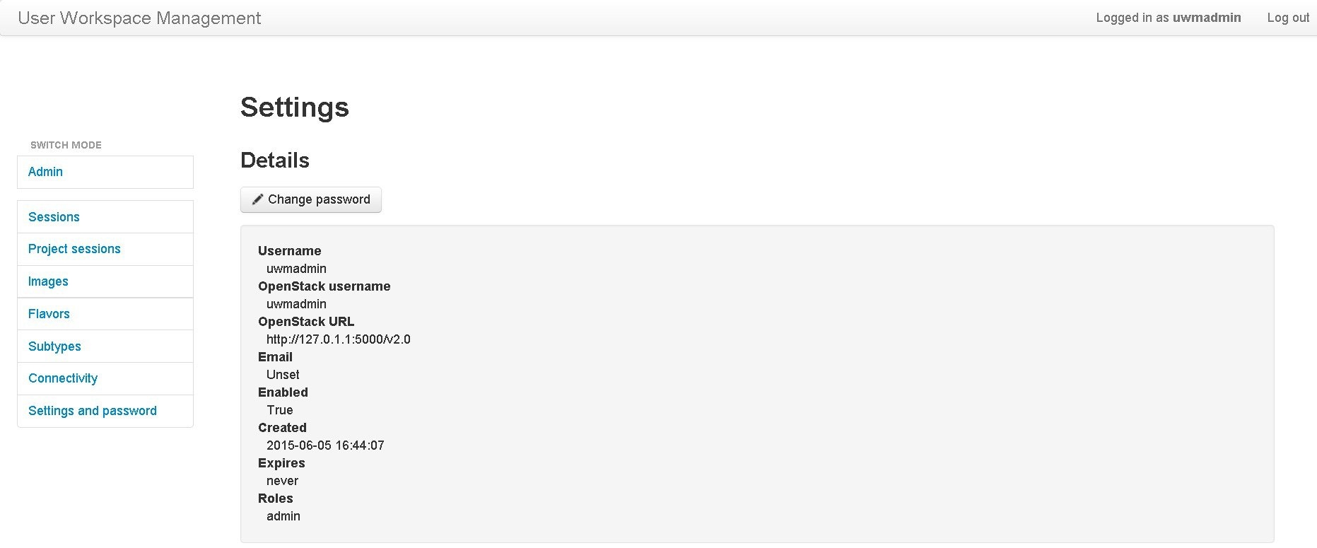
The uwmadmin account is used to manage server resources and user access. Therefore, to reduce the risk of unauthorized access, we recommend that you change the default password for the uwmadmin account to a more secure password on initial login.
Admin Mode Versus User Mode
When you log into the User Management Workspace interface as administrator, there are two modes of operation available to you; these are Admin and User. The following tables describe the different functions available for each mode.
|
Function |
Description |
|---|---|
|
Projects |
Allows you to import and export projects. You can also add new projects, enable, disable, modify, and delete current projects. |
|
Users |
Allows you add new users, enable, disable, modify, and delete current users. |
|
Images |
Allows you add new images, modify, and delete current images. You can also modify and delete image snapshots. |
|
Flavors |
Allows you add and delete flavors. |
|
Subtypes |
Allows you to import and export subtypes. You can also create a custom subtypes, using the specialize option. You create a new subtype based on one of the available built in subtypes. |
|
Connectivity |
Allows you to add and delete L2 Flat IP, L3 Snat IP, and Management IP allocations for projects. |
|
Statistics |
Provides system statistics for system status, projects and users, simulations and AutoNetkit usage. |
|
VM Control |
Allows you to delete nodes, networks, ports and IP allocations when problems are encountered. |
|
Function |
Description |
|---|---|
|
Images |
Allows you add new images, modify, and delete current images. You can also modify and delete image snapshots. |
|
Flavors |
Lists details for the available flavors. |
|
Subtypes |
Lists details for the available subtypes. |
|
Connectivity |
Lists details for the available connections. |
|
Settings and Password |
Allows you to change your password. |
Manage Projects
Within the User Workspace Management interface, a project represents a set of resources that are available to each project. It has the following characteristics:
- By default, a project user account is created for each project.
- To add a user as a standalone user, a project must be assigned to the user. Also, the username will be the project name.
- Additional users can be assigned to a project as required.
- If a user is added to a project, the username of the user is prefixed with the project name.
- Deleting a user account does not delete a project that the user is assigned to.
- Deleting a project deletes only the associated default user; nondefault user accounts are not deleted.
|
Operation |
Description |
|---|---|
|
Import |
Imports a project and its users from a JavaScript Object Notation (JSON) or tab-Separated values (TSV) file. |
|
Export |
Exports a project and its users as a JSON or TSV file. |
|
Add |
Creates a new project. |
|
Enable |
Enables a selected project. |
|
Disable |
Disables a selected project. |
|
Modify |
Modifies details for a selected project. |
|
Delete |
Deletes a selected project and its users. |
Import a Project
Files for import must be in the JSON or TSV format and must have previously been exported from the User Workspace Management interface.
To import a project and its users, complete the following steps:
Export a Project
To export a project and its users, complete the following steps:
| Step 1 | In the User Workspace Management interface, in admin mode, click Projects. The Projects page, which lists all of the current projects, appears. |
| Step 2 | Check the check box beside the project or projects for export. |
| Step 3 | Click
Export to
export the applicable project and projects and all its users.
|
| Step 4 | From the drop-down list, choose the type of file to export to, JSON or TSV. The Open dialog box appears. |
| Step 5 | Click the Save radio button and click OK to save the file. The exported file is saved to the specified location. |
Create a Project
To create a new project, and a user for the project complete the following steps:
| Step 1 | In the
User Workspace
Management interface, in admin mode, click
Projects.
The Projects page, which lists all of the current projects, appears. | ||
| Step 2 | Click
Add to
create a new project.
The
Create
Project page appears.
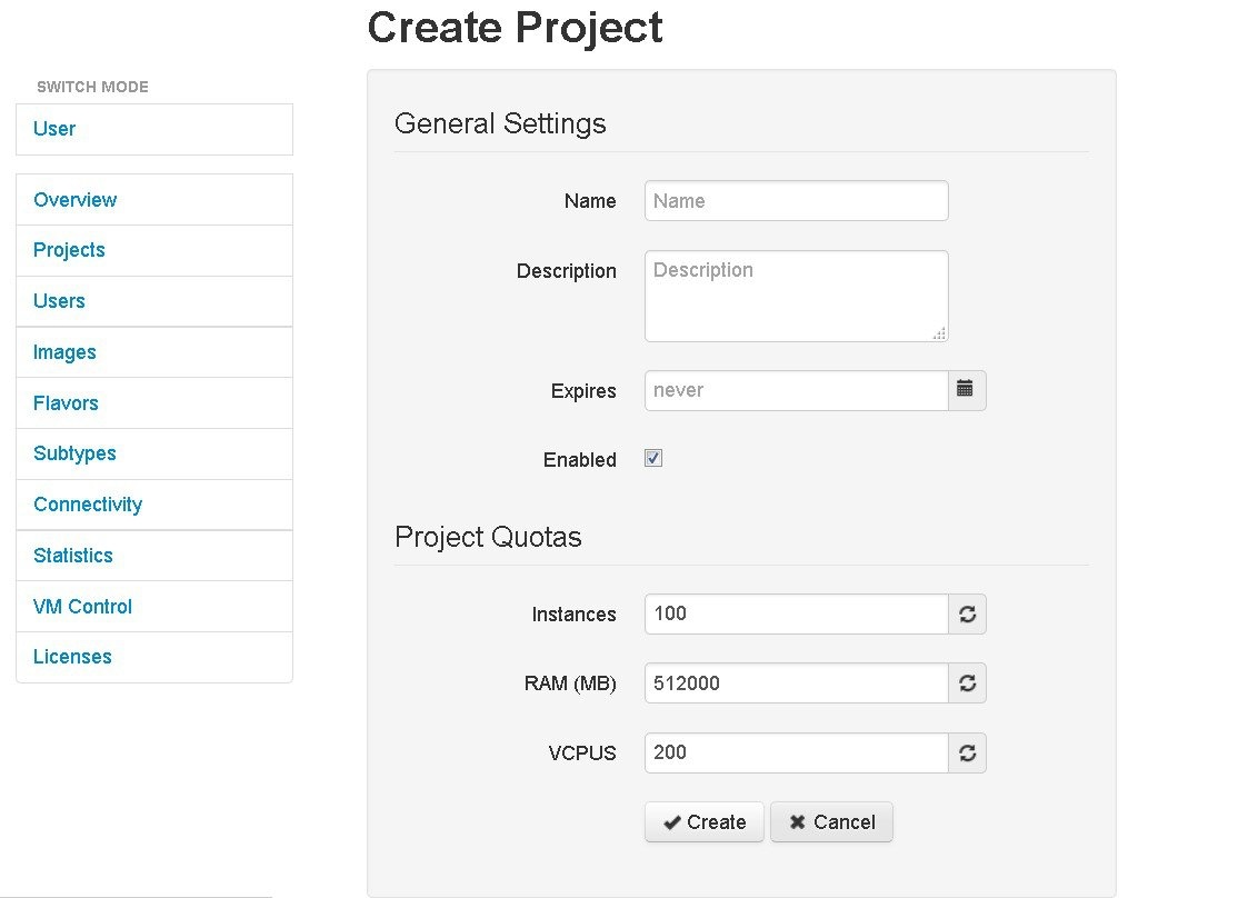 | ||
| Step 3 | Under General Settings, add a name and a description for the project. In the Expires field, you can either add an expiry date for the project or accept the default, which is Never, meaning the project will never expire. Leave the Enabled check box checked to enable the project for use. | ||
| Step 4 | Under
Project
Quotas, you can either accept the default values for the system quotas or
increase or decrease them based on your project requirements:
| ||
| Step 5 | Click
Create.
The Edit User page appears. 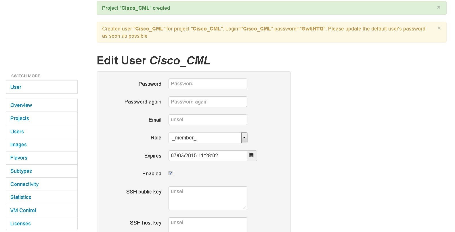
Using this window, you can add details for the new user created when the project is created. | ||
| Step 6 | In the
Password and
Password
Again fields, enter a new password for the user.
| ||
| Step 7 | In the Email field, add a valid email address for the user. By default, the user is assigned a member role. | ||
| Step 8 | In the Expires field, you can add an expiry date for the user or accept the default Never. Leave the Enabled check box checked to enable the project for immediate use. Alternatively, you can set up a project and users, but you cannot enable them to be configured and available at a later time. | ||
| Step 9 | Click Save to save the changes for the user. | ||
| Step 10 | (Optional) To confirm that the project has been added, click Projects to view the newly added project, and click Users to view the newly added user. Otherwise, logout. |
Manage Users
Within the User Workspace Management interface, you can manage user accounts from the Users page. User accounts permit access to the Cisco Modeling Cisco Modeling Labs server from the Cisco Modeling Labs client.
In the Users page, you can perform a number of operations for users. These operations are:
|
Operation |
Description |
|---|---|
|
Add |
Creates a new user account. |
|
Enable |
Enables a selected user account. |
|
Disable |
Disables a selected user account. |
|
Modify |
Modifies details for a selected user account. |
|
Delete |
Deletes a selected user account. |
Create a User
To create a new user, complete the following steps:
| Step 1 | In the User Workspace Management interface, in admin mode, click Users. The Users page, which lists all the default users, appears. | ||
| Step 2 | Click
Add to
create a new user.
The Create User page appears. 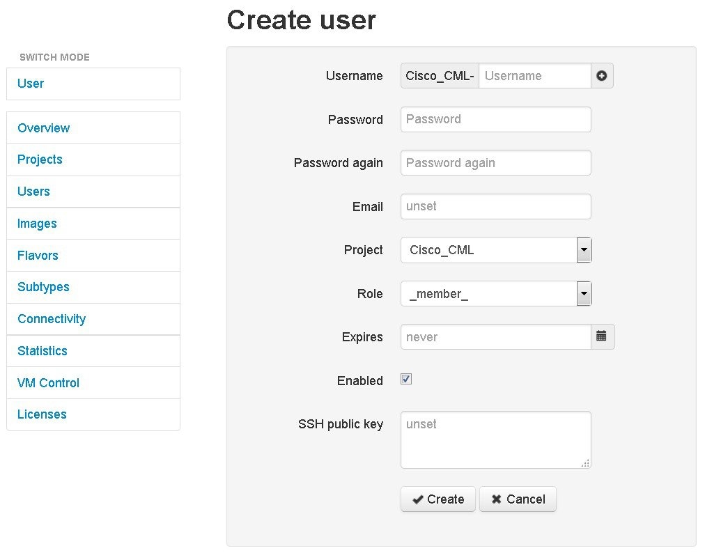 | ||
| Step 3 | In the
Username
field, enter a username for the new user.
| ||
| Step 4 | In the Password and Password Again fields, enter a password for the new user. | ||
| Step 5 | In the Email field, enter a valid email address for the user. | ||
| Step 6 | From the Project drop-down list, choose the applicable project for the user. | ||
| Step 7 | From the
Role
drop-down list, choose the applicable role for the user.
| ||
| Step 8 | In the Expires field, you can either add an expiry date for the user or accept the default, which is Never. | ||
| Step 9 | Leave the Enabled check box checked. | ||
| Step 10 | Click
Create.
The User <Project Name>-<Username> page appears. This page presents details and project quotas for the user. | ||
| Step 11 | (Optional) Click Modify User to amend the details for a user, or click Delete User to delete a user. | ||
| Step 12 | Click Users to view the newly created user. |
Expire a User Account
While the option to disable a user account is available in the User Workspace Management interface, it is advisable that you expire a user account rather than disable it. When a user account with running simulations is disabled, the project is effectively frozen and simulations can only be stopped by the administrator via VM Control. However, if a user account with running simulations is expired, the administrator can stop the running simulations for the expired user account.
To expire a user account, complete the following steps:
| Step 1 | In the User Workspace Management interface, in admin mode, click Users. The Users page, which lists all of the default users, appears. |
| Step 2 | Click the user account to be expired. The User Details page appears. |
| Step 3 | In the Expires field, enter an expiry date and time for the user account, or use the calender icon. |
| Step 4 | Click
Save.
The User Details page appears and shows the expiry date for the user account. |
Manage VM Images
Within the User Workspace Management interface, you can add new images, update details for existing images, or delete images from the system. Additionally, you can take a snapshot of the disk content of a virtual machine image. This newly created user-specific disk image can be used in other simulated sessions.
-
Cisco Virtual IOS (IOSv) Software Release 15.5(3)M
-
Cisco IOSv Layer 2 Switch Software Release 15.2.(4.0.63)E
-
Linux server (Ubuntu 14.04.2 LTS Cloud-init)
In the Images page, you can perform a number of operations for images. These operations are:
|
Operation |
Description |
|---|---|
|
Add |
Creates a new virtual machine image. |
|
Modify |
Modifies details for a selected virtual machine image. |
|
Delete |
Deletes a selected virtual machine image. |
Create a Virtual Machine Image
To create a new virtual machine image, complete the following steps:
| Step 1 | In the
User Workspace
Management interface, in admin mode, click
Images.
The Images page, which lists all of the available registered images, appears.
| ||
| Step 2 | Click
Add to
create a new image.
The Create Shared VM Image page appears. 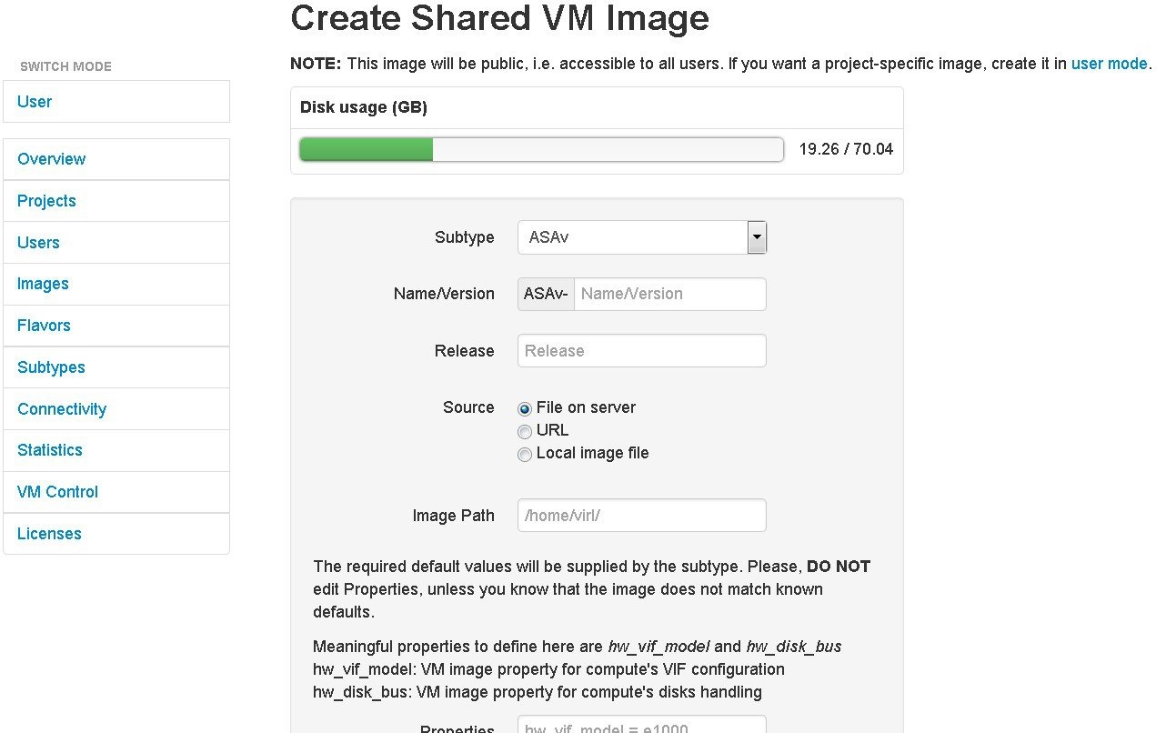 | ||
| Step 3 | From the Subtype drop-down list, choose the appropriate subtype for the new image. | ||
| Step 4 | In the Name/Version field, enter a name or version number for the image. | ||
| Step 5 | In the Image Path field, enter a path on the server/virtual machine (an HTTP, FTP or TFTP URL) or choose a file to upload. | ||
| Step 6 | To upload an image from your own device, click Browse to navigate to the image file. | ||
| Step 7 | Leave the Properties field blank because by default, appropriate properties are automatically set based on the chosen subtype. | ||
| Step 8 | Click
Create to
create your virtual machine image.
The Image <Image Name> page, which contains the details and properties of the virtual machine image, appears. | ||
| Step 9 | Click Images to view the newly added image. | ||
| Step 10 | Under the Options column, use the Modify or Delete options to amend the details for the virtual machine or to delete a virtual machine image. After the image is installed, it is available for users to select for their topology simulation. | ||
| Step 11 | In the Cisco Modeling Labs client, click | ||
| Step 12 | In the Node Subtypes dialog box, click Fetch from Server. The Confirm dialog box is displayed. | ||
| Step 13 | Click OK to update the list of node subtypes based on the currently configured Cisco Modeling Labs server. |
Create an Image Snapshot
When a Linux server is present in a running simulation, you can take a snapshot of the disk content of the server. This newly created user-specific disk image can be used in other simulated sessions.
To take a snapshot of the server's disk content, complete the following steps.
| Step 1 | Log in to the
User Workspace
Management interface.
| ||
| Step 2 | On the Overview page, under Sessions, choose the applicable running session. A list of active virtual machines is displayed. | ||
| Step 3 | Choose the
applicable virtual machine image, and from the
Options
drop-down list, click
Create
Snapshot.
Project
details for the newly created snapshot are displayed.
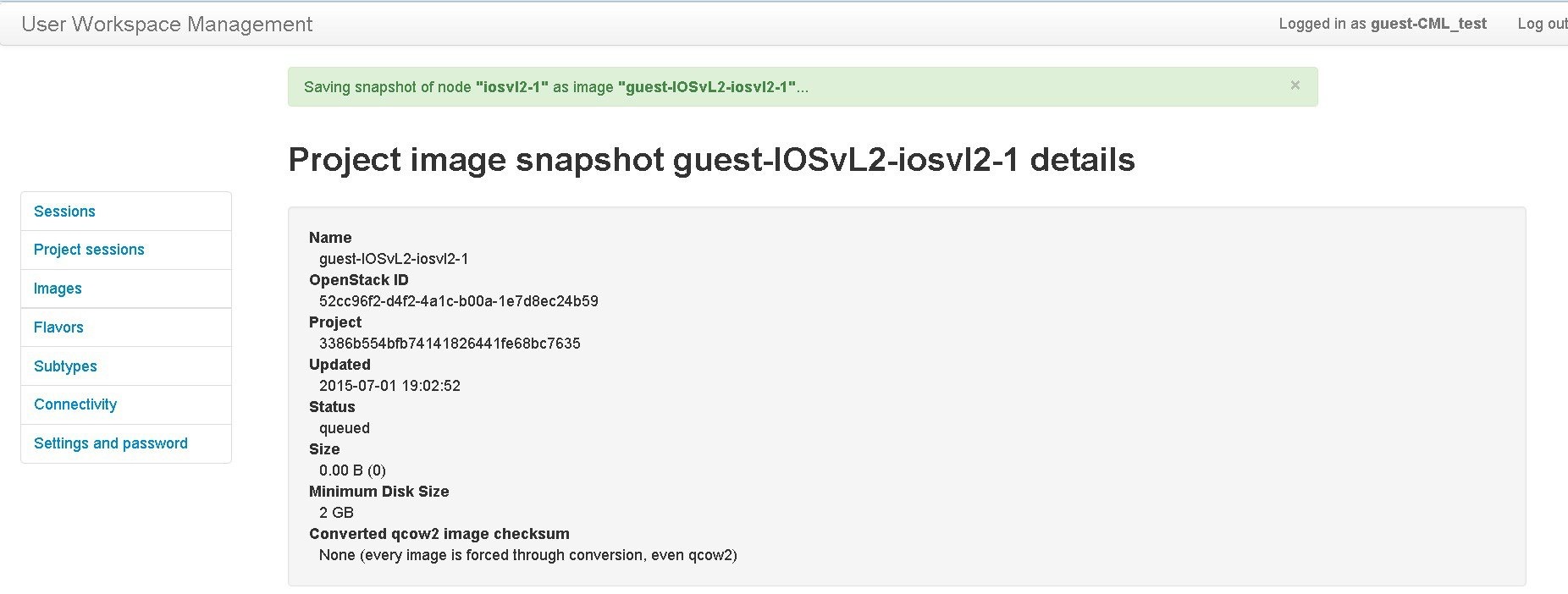 The image snapshot can be reused in the Cisco Modeling Labs client under See Cisco Modeling Labs Corporate Edition User Guide, Release 1.1 for more information. |
Manage Virtual Machine Flavors
Within the User Workspace Management interface, as part of the creation process for virtual machine images, a virtual machine flavor is created. Flavors are used in each virtual machine to define the CPU, memory (RAM) allocation, disk space, the number of cores, and so on.
|
Operation |
Description |
|---|---|
|
Add |
Creates a new flavor. |
|
Delete |
Deletes a selected flavor. |
Create a Virtual Machine Flavor
To create a new virtual machine flavor, complete the following steps:
| Step 1 | In the
User Workspace
Management interface, in admin mode, click
Flavors.
The Flavors page, which lists all of the available flavors, appears. |
| Step 2 | Click
Add to
create a new flavor.
The Create Flavor page appears. 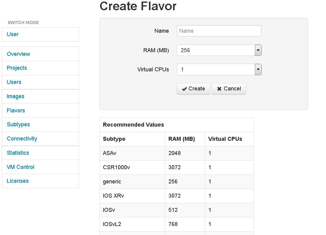 |
| Step 3 | In the Name field, enter a name for the flavor. |
| Step 4 | From the RAM drop-down list, choose the amount of memory allocation for the flavor. |
| Step 5 | From the Virtual CPUs drop-down list, choose the number of virtual CPUs for the flavor. |
| Step 6 | Click
Create to
create your virtual machine flavor.
The Flavors page appears with the newly created flavor listed. |
| Step 7 | Under the Options column, use the Delete option to delete a virtual machine flavor. |
Manage Subtypes
In the User Workspace Management interface, the Subtypes page provides a list of integrated subtypes, which users can use as templates to create their own custom subtypes. Using the Specialize option for a subtype, a user can duplicate the subtype template make the necessary updates to create a new custom subtype. Subtypes can be imported and exported, which allows users to apply their custom subtypes to other Cisco Modeling Labs server installations.
|
Operation |
Description |
|---|---|
|
Import |
Imports a subtype from a JSON file. |
|
Export |
Exports a subtype to a JSON or TSV file. |
|
Specialize |
Duplicates an available subtype to create a custom subtype. |
Import a Subtype
Subtypes for import must be available in a JSON file.
To import a subtype, complete the following steps:
| Step 1 | In the User Workspace Management interface, in admin mode, click Subtypes. The Subtypes page, which lists the integrated subtypes, appears. |
| Step 2 | Click
Import to
import a new subtype.
The Import Subtypes page appears. |
| Step 3 | In the text area, paste the subtype details from the JSON file. |
| Step 4 | Click Import. The newly imported subtype is listed on the Subtypes page. |
| Step 5 | (Optional) Click Specialize to create a custom subtype based on the newly imported subtype, click Modify to amend the details for the subtype, or click Delete to delete the subtype. |
Create a Custom Subtype
To create a custom subtype, complete the following steps:
| Step 1 | In the User Workspace Management interface, in admin mode, click Subtypes. The Subtypes page, which lists the integrated subtypes available, appears. | ||||||||||||||||||||||||||||||||||||||||||||||||||
| Step 2 | For the applicable subtype, click the Options drop-down list next to it and click Specialize. The Specialize Subtype page appears. | ||||||||||||||||||||||||||||||||||||||||||||||||||
| Step 3 | Update the
subtype fields as required.
| ||||||||||||||||||||||||||||||||||||||||||||||||||
| Step 4 | When completed,
click
Create to
create the new custom subtype.
The new
subtype is created and its details are displayed in the
Subtypes page for the new subtype.
| ||||||||||||||||||||||||||||||||||||||||||||||||||
| Step 5 | (Optional) On this page, you can click Specialize to create a custom subtype based on the newly created subtype, click Modify to amend the details for the subtype, or click Delete to delete the subtype. | ||||||||||||||||||||||||||||||||||||||||||||||||||
| Step 6 | Click the Subtypes tab to see the custom subtype listed on the page. |
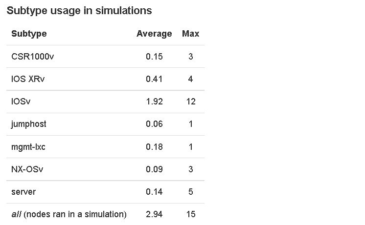
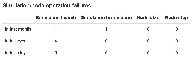
System Statistics
You can view various statistics concerning the usage and operation of your Cisco Modeling Labs system. System statistics are available from the Statistics option on the left-hand side of the interface.
The following areas are covered:
|
Area |
Description |
|---|---|
|
System Status |
Provides a summary of the Cisco Modeling Labs server system state. Includes information on CPU cores, memory, and disk space (total and free). In addition, it provides a snapshot of the memory usage history for the last week, the last month, and the previous 24 hours; the snapshot includes the average and maximum percentages used. 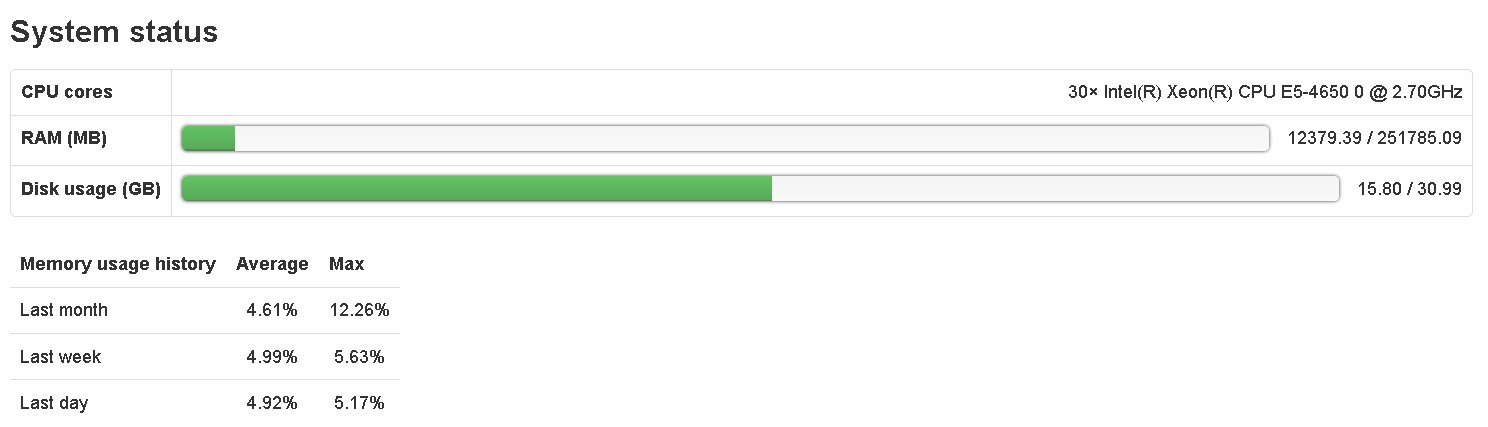 |
|
Projects and Users |
Lists the number of currents projects and users.  |
|
Simulations |
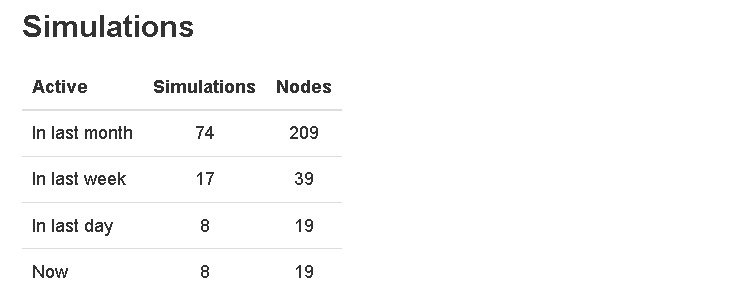 |
|
AutoNetkit |
Lists details for the number of configurations generated in the last week, the last month, and the previous 24 hours, including the number of invalid topologies encountered. The category Subtype Usage in Configured Topologies lists the subtypes used in configuration requests along with their average and maximum usage stats. 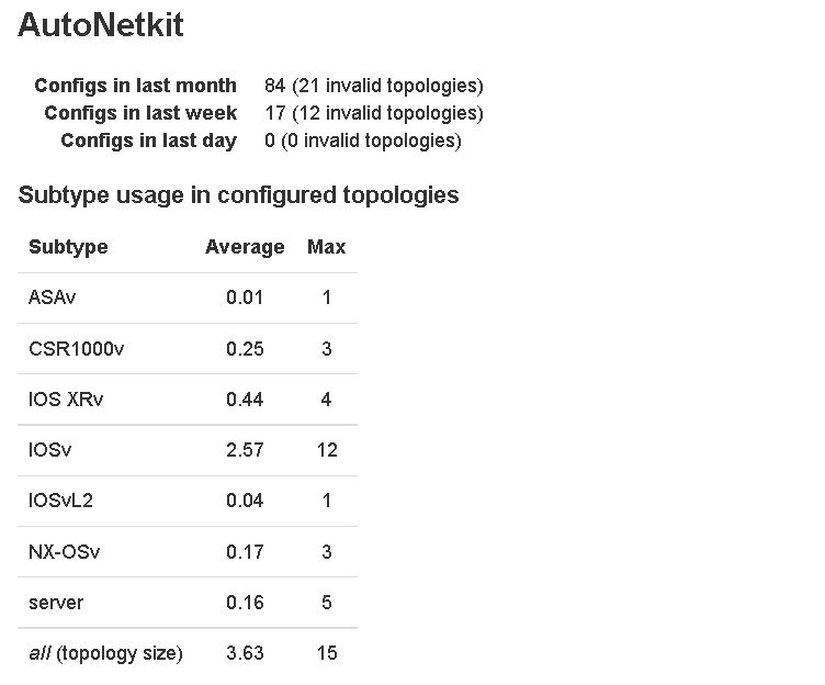 |
Connectivity
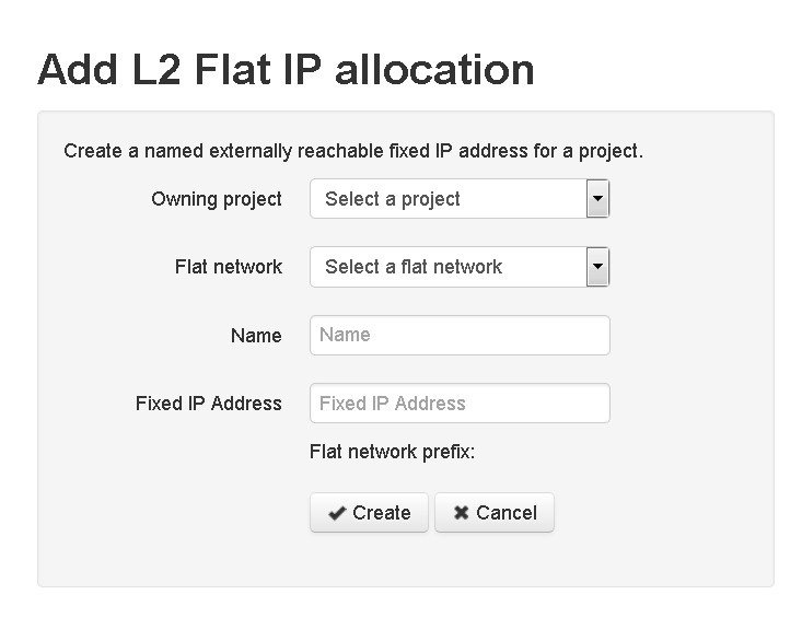
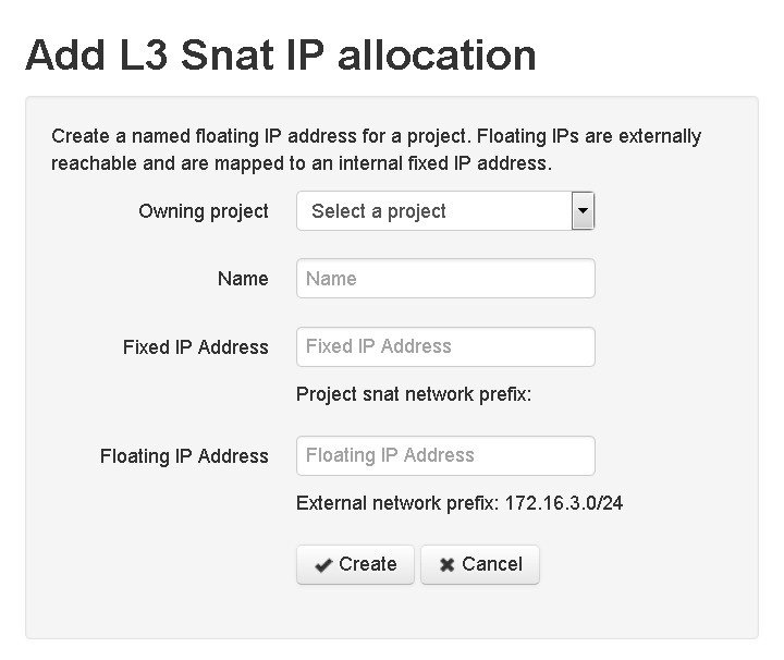
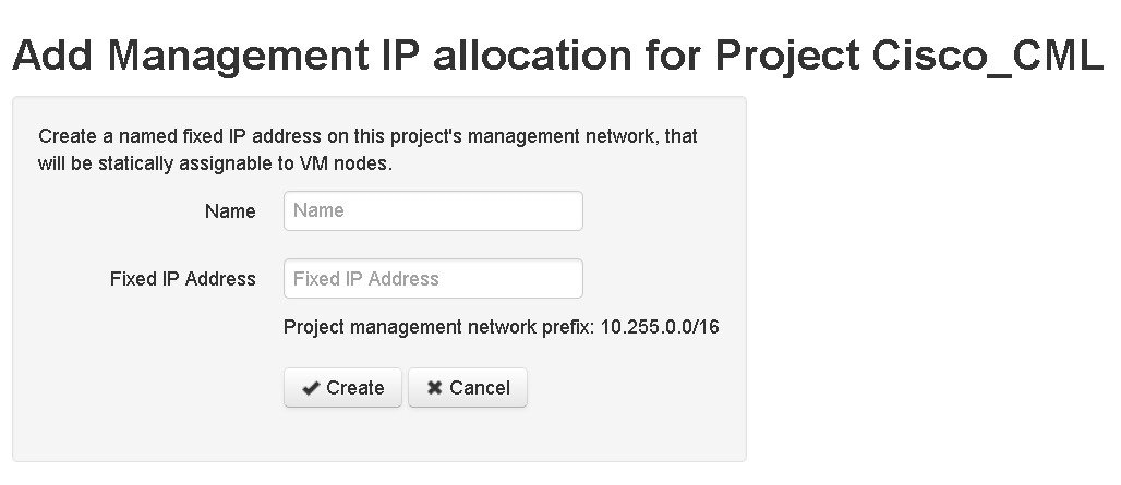
Within the User Workspace Management interface, the Connectivity page provides details on all OpenStack ports available on the external (FLAT and SNAT) and project management networks
- L2 FLAT IP address allocations—Create an externally reachable fixed IP address for a project.
- L3 SNAT IP address allocations—Create a floating IP address for a project. Floating IPs are externally reachable and are mapped to an internal fixed IP address.
- Project Management IP address allocations—Create a fixed IP address on the management network of the selected project. This IP address can be statically assigned to the nodes.
|
Operation |
Description |
||
|---|---|---|---|
|
Add |
Creates a new OpenStack port connection for L2 Flat, L3 SNAT, or Project Management. |
||
|
Delete |
|
Create an OpenStack Port Connection
To create a new port connection, complete the following steps:
| Step 1 | In the User Workspace Management interface, in admin mode, click Connectivity. The Outside Connections page, which lists all current port connections appears. | |||||||||||||||||||||||||||||||||
| Step 2 | Connections are
grouped into three areas:
L2 FLAT,
L3 SNAT,
and
Project
Management. Click
Add in the
applicable group to create the required port connection for that type.
The corresponding Add IP Allocation page appears. | |||||||||||||||||||||||||||||||||
| Step 3 | Complete the
fields as required for the applicable port connection.
| |||||||||||||||||||||||||||||||||
| Step 4 | Click
Create.
The new connection is created and its details are displayed in the Connectivity page. |
Using the VM Control Tool
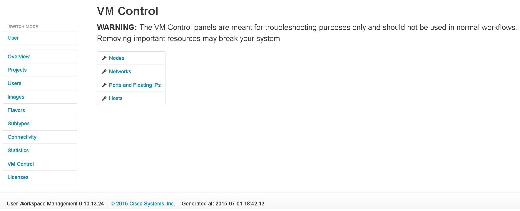
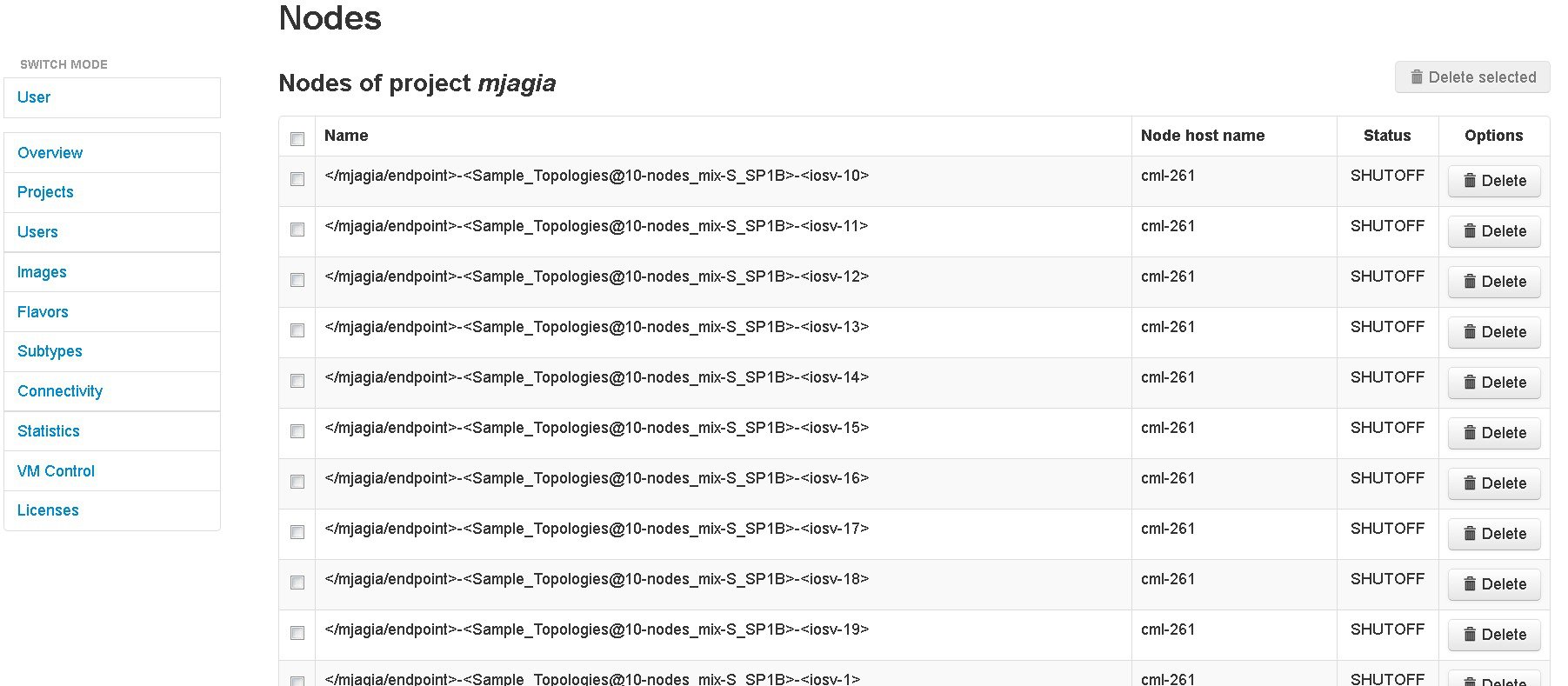
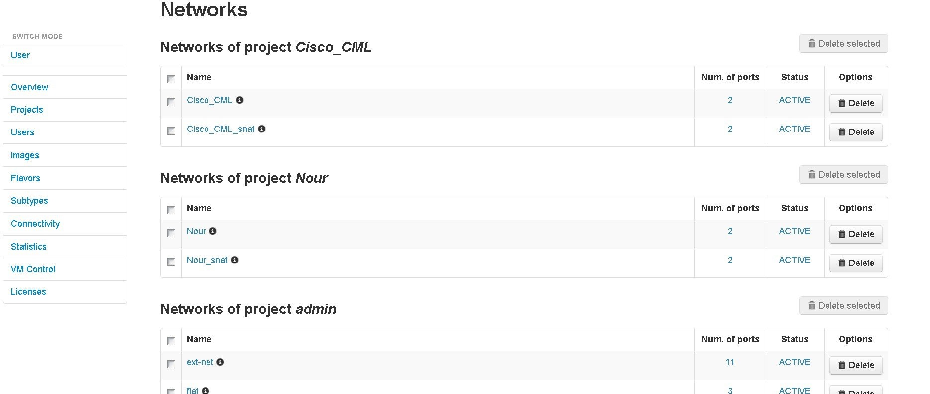
The applicable components are:
VM Control Nodes
VM Control Networks
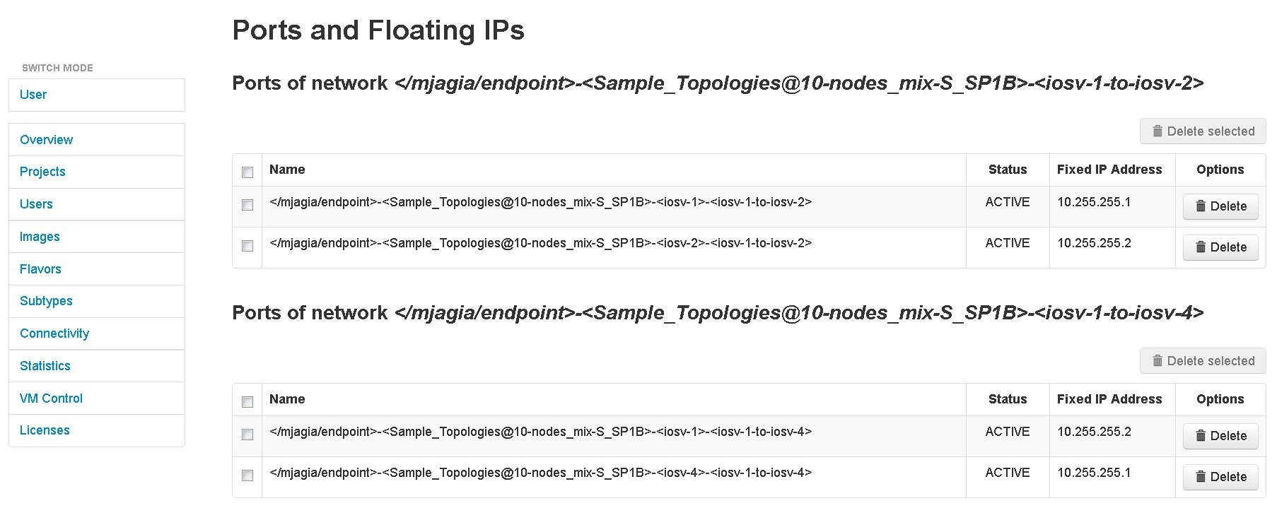
VM Control Ports and Floating IPs
VM Control Hosts
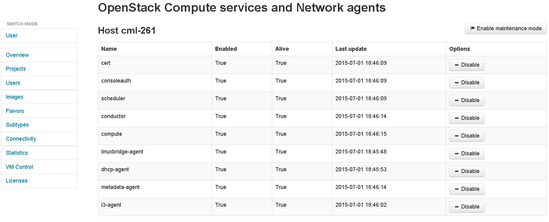
The VM Control Hosts page lists all the compute services and network agents. Maintenance mode on a host disables the compute service on that node. It prevents new virtual machine from being deployed on that host.
Manage Cisco Modeling Labs Licenses
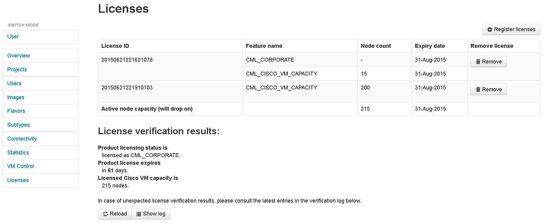
Within the User Workspace Management interface, you can manage Cisco Modeling Labs licenses. A license specifies the options that are enabled for Cisco Modeling Labs.
Register a Cisco Modeling Labs License
| Step 1 | Open the email containing your Cisco Modeling Labs license key. |
| Step 2 | Using a text editor, open the attached .lic file. |
| Step 3 | In the User Workspace Management interface, in admin mode, click Licenses. The Licenses page, which lists all valid licenses, appears. |
| Step 4 | Click Register License to
register a valid license.
The
Register
licenses page appears.
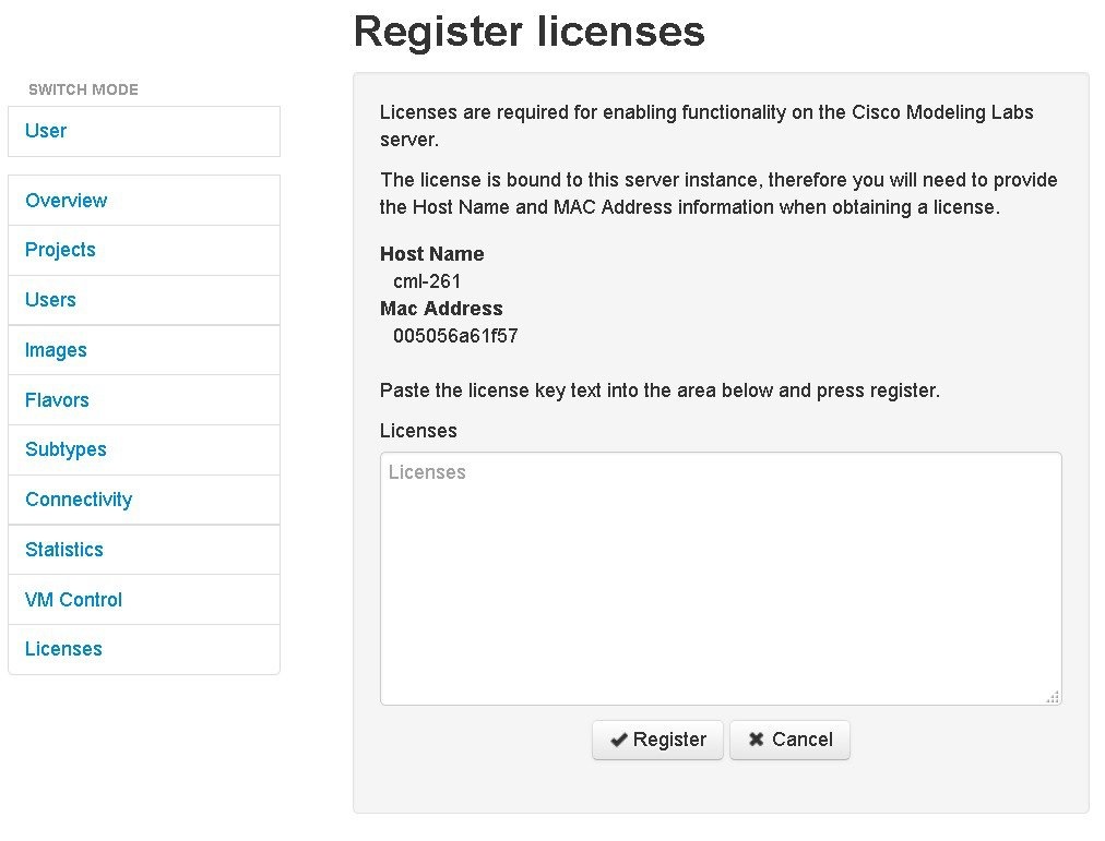 |
| Step 5 | Copy and paste the license key from the .lic file into the Licenses text area. |
| Step 6 | Click Register. The license is applied. |
| Step 7 | Return to the Licenses page to view the newly registered license. |
Stop Active Sessions in the User Workspace Management Interface
If you are a system administrator, you can terminate active sessions from within the User Workspace Management interface. You can select one or more sessions to terminate, including sessions started by other users.
If you are a client user, you can only terminate a session from within the User Workspace Management interface that you started.
Details on stopping a single session or stopping all sessions for a particular project are discussed in the following section.
Stop an Active Session
The Overview page lists all the active sessions for all the currently running projects for all the users. You can stop a specific session, or all the sessions for a specific project or projects.
 Feedback