Cisco Modeling Labs Corporate Edition System Administrator Installation Guide, Release 1.1
Bias-Free Language
The documentation set for this product strives to use bias-free language. For the purposes of this documentation set, bias-free is defined as language that does not imply discrimination based on age, disability, gender, racial identity, ethnic identity, sexual orientation, socioeconomic status, and intersectionality. Exceptions may be present in the documentation due to language that is hardcoded in the user interfaces of the product software, language used based on RFP documentation, or language that is used by a referenced third-party product. Learn more about how Cisco is using Inclusive Language.
- Updated:
- September 29, 2015
Chapter: Cisco Modeling Labs ISO Installation
- Cisco Modeling Labs ISO Disk Image Installation
- Prepare for an ISO Disk Image Installation
- Download the Cisco Modeling Labs ISO Disk Image
- Cisco UCS B-Series Server Installation
- Cisco UCS C-Series Server Installation
- Install the Cisco Modeling Labs ISO Disk Image
- (Optional) Prepare for an Interface-Constrained Installation
- (Optional) Configure Static IP
- (Optional) Configure Internet Proxies
- Customize the Cisco Modeling Labs Configuration
- Determine License Key Requirements
Cisco Modeling Labs ISO Installation
Cisco Modeling Labs ISO Disk Image Installation
This chapter details the ISO disk image installation procedure for a bare metal environment.
A bare metal implementation is a computer system in which the software for a virtual machine is installed directly on hardware rather than as a virtual machine on top of a hypervisor system, such as VMware ESXi, within the host operating system. The term bare metal refers to a hard disk, the usual medium on which a computer's operating system is installed.
 Note | These hardware configurations are for example purposes only; you can deploy the server implementation that best suits your requirements. |
Prepare for an ISO Disk Image Installation
Using an ISO disk image to install Cisco Modeling Labs is required when installing to bare metal servers.
There is a number of key prerequisites that must be in place in order to use an ISO disk image to successfully install Cisco Modeling Labs.
These prerequisites are:
-
The host must support Intel VT-x/EPT virtualization extensions, and these extensions must be enabled in the BIOS.
-
The target disk must be at least 250 GB and must not contain any irreplaceable data, as it will be repartitioned and erased.
-
There must be five network interfaces.
-
If static IP addressing and/or proxies are required, see the section (Optional) Configure Static IP.
-
For installations to bare-metal, you must create a DVD from the ISO disk image or, alternatively, attach the ISO disk image via an integrated management interface (such as UCS or Cisco Integrated Management Controller.)
-
For installations to a virtual machine, the following hypervisors are supported: -
VMware vSphere ESXi 5.1 U2 (Build 1483097) or later.
-
VMware vSphere ESXi 5.5 U1 (Build 1623387) or later.
-
VMware vSphere ESXi 6.0 (Build 2494585).
Note
Additionally, you must verify that you are using vSphere Client v5.5 Update 2 (Build 1993072) or later before deploying Cisco Modeling Labs. Failure to use the minimum version will result in a failed deployment that will return an error stating that nested virtualization is not supported.
Note
Oracle VirtualBox is not supported due to its lack of support for nested virtual machines. -
-
You must configure five virtual network interfaces and map them to separate port groups. The port groups mapped to the second and third network interfaces must be set to Promiscuous Mode. See the applicable hardware documentation for details and examples of how to configure network interfaces.
-
When creating virtual machines, the guest operating system type must be set to Other Linux 64-Bit or Other Linux 3.x Kernel 64-Bit. The following table outlines how to set the guest operating system type for each hypervisor. Hypervisor
Instructions
VMware Workstation
Select the new Cisco Modeling Labs virtual machine and choose . Set the guest operating system to Linux and version to Other Linux 3.x Kernel 64-Bit.
VMware vSphere Client
Select the new Cisco Modeling Labs virtual machine and choose . Set the guest operating system to Linux and version to Other Linux 3.x Kernel 64-Bit.
VMware vSphere Web Client
Select the new Cisco Modeling Labs virtual machine and choose . Set guest operating system to Linux and version to Other Linux 3.x Kernel 64-Bit.
-
Time synchronization must be disabled for the Cisco Modeling Labs virtual machine in the Advanced or Options panel of the virtual machine settings. The following table outlines how to disable time synchronization for each hypervisor. Hypervisor
Instructions
VMware Workstation
Select the new Cisco Modeling Labs virtual machine and choose . Uncheck the Synchronize Guest Time with Host check box.
VMware vSphere Client
Select the new Cisco Modeling Labs virtual machine and choose . Uncheck the Synchronize Guest Time with Host check box.
VMware vSphere Web Client
Select the new Cisco Modeling Labs virtual machine and choose . Uncheck the Synchronize Guest Time with Host check box.
Note | Failing to set the guest operating system to Other Linux 64-Bit or Other Linux 3.x Kernel 64-Bit will prohibit you from setting the hostname during the installation process, resulting in a failed installation. Depending on Internet speed and target platform performance, an installation can take between 30 and 60 minutes. |
Download the Cisco Modeling Labs ISO Disk Image
You must download the Cisco Modeling Labs ISO disk image using the link provided in your purchase confirmation email.
The OVA files are large (~4 GB), so rather than HTTP downloads using a web browser, the use of a download manager for Mac or Windows is recommended.
An MD5 hash sum for the ISO disk image is provided along with the download link on the download website. You must calculate and verify that the hash sum of the downloaded ISO disk image matches the source file:
Cisco UCS B-Series Server Installation
The following sections describe how to install the Cisco Modeling Labs ISO disk image on a Cisco UCS B-Series Server.
- Log In to the Cisco UCS Manager Interface
- Map the Cisco Modeling Labs ISO Disk Image on a Cisco UCS B-Series Server
Log In to the Cisco UCS Manager Interface
The default HTTPS weblink for the Cisco UCS Manager interface is https://UCSManager_IP, where UCSManager_IP represents the IP address assigned to Cisco UCS Manager.
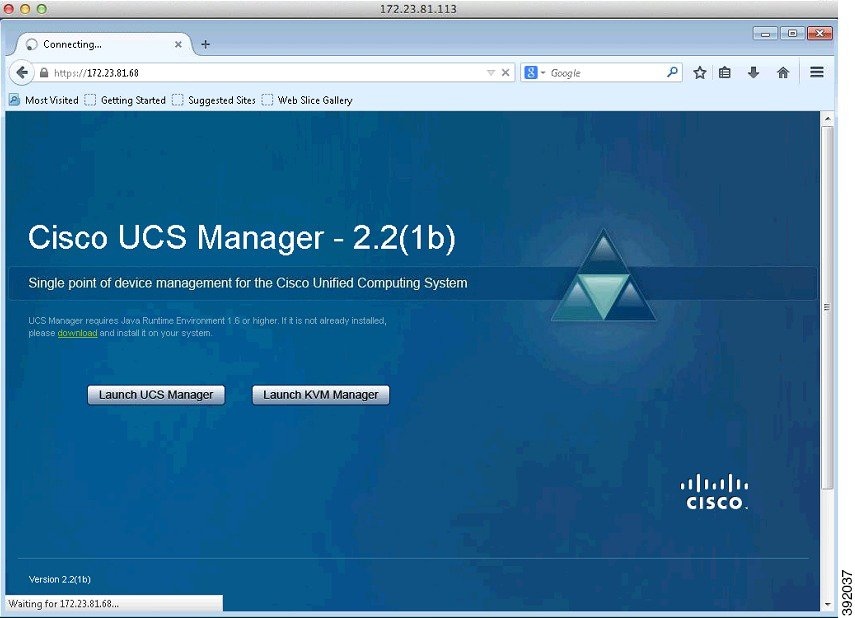
Map the Cisco Modeling Labs ISO Disk Image on a Cisco UCS B-Series Server
Note | This procedure requires you to have downloaded the Cisco Modeling Labs ISO disk image and to ensure it is accessible from the computer that you are using to log in to the Cisco UCS Manager interface. |
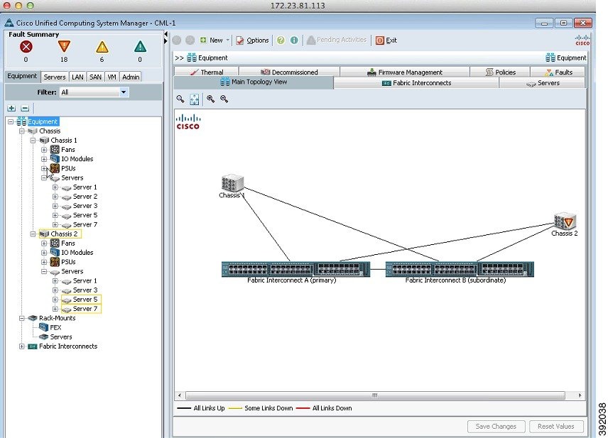
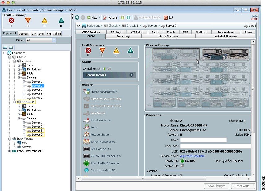
To map the Cisco Modeling Labs ISO disk image, complete the following steps:
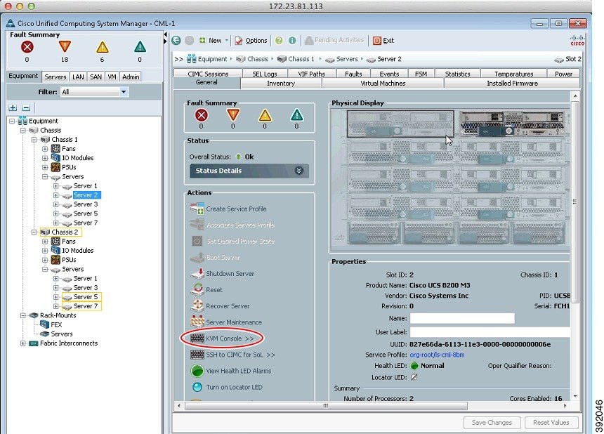
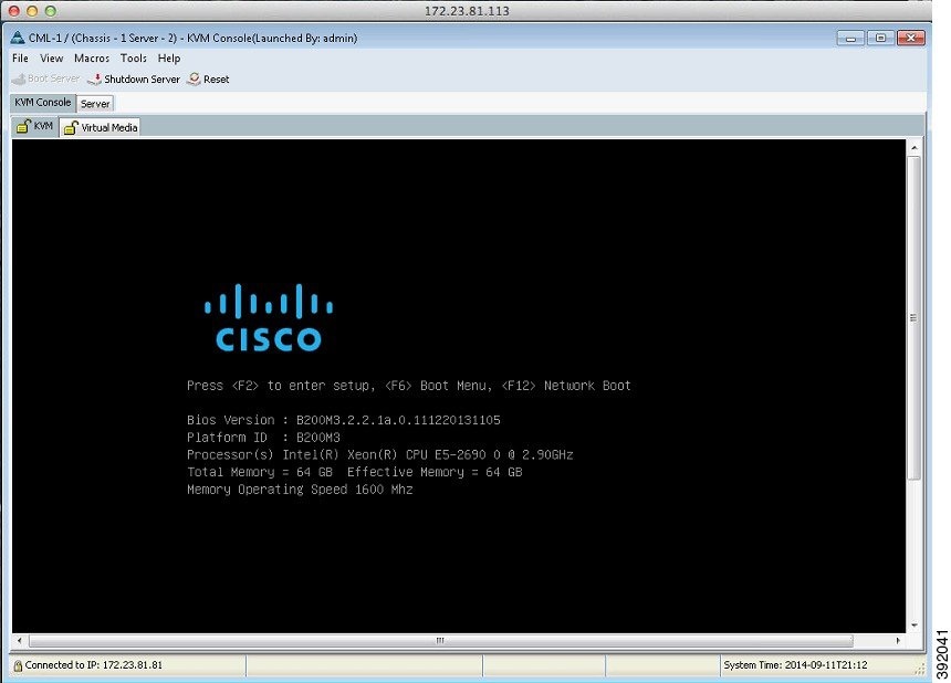
Cisco UCS C-Series Server Installation
The following sections describe how to install the Cisco Modeling Labs ISO disk image on a Cisco UCS C-Series Server.
- Log In to the Cisco Integrated Management Controller Interface
- Map the Cisco Modeling Labs ISO Disk Image on a Cisco UCS C-Series Server
Log In to the Cisco Integrated Management Controller Interface
The default HTTPS web link for CIMC is https://ip-address.
| Step 1 | Open a browser and enter the IP address of the CIMC interface in the format https://ip-address. | ||
| Step 2 | If prompted, click OK to open Java viewer.jnlp. | ||
| Step 3 | If a security dialog box is displayed, perform the following tasks: | ||
| Step 4 | In the CIMC
login window, enter the username and password for the CIMC interface.
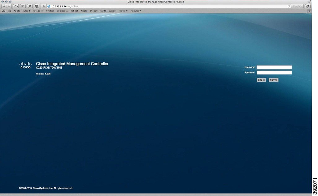 | ||
| Step 5 | Click Log In. |
Map the Cisco Modeling Labs ISO Disk Image on a Cisco UCS C-Series Server
Note | This procedure requires you to have downloaded the Cisco Modeling Labs ISO disk image file and to ensure it is accessible from the computer that you are using to log in to the Cisco Integrated Management Controller (CIMC) interface. |
To map the Cisco Modeling Labs ISO disk image, complete the following steps:
| Step 1 | Under the
General tab,
click
KVM Console to
launch the KVM Console and connect to the KVM server.
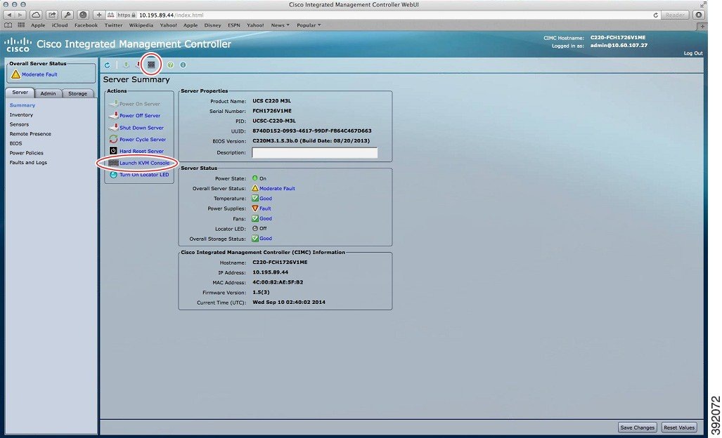 | ||||
| Step 2 | If a security dialog box is displayed, perform the following tasks: | ||||
| Step 3 | At the Cisco KVM Virtual Console confirmation box, perform the following tasks: | ||||
| Step 4 | In the KVM Console, click the Virtual Media tab. In the KVM Console, the ISO disk image is mapped to the server so that at boot time, the server boots from the ISO disk image. | ||||
| Step 5 | Click
Add Image.
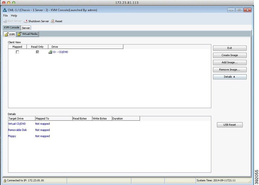 | ||||
| Step 6 | From the dialog
box that is displayed, navigate to the location of the Cisco Modeling Labs ISO
disk image, click the corresponding image and click
Open.
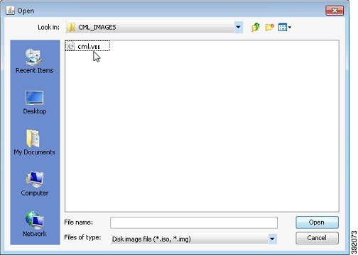 | ||||
| Step 7 | The path to the
ISO disk image is visible in the
Client View.
Check the
Mapped check
box to allow the image file to be accessed by the server. Uncheck the check box
to disconnect the server from the drive or disk image.
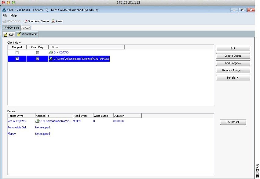 | ||||
| Step 8 | Click the
KVM tab. The No
Signal window is displayed.
The No Signal window indicates that the server is not powered on. 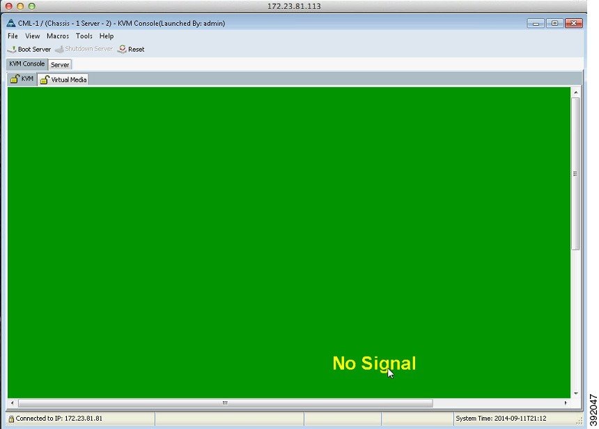 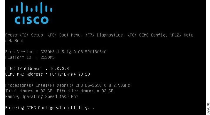 | ||||
| Step 9 | Press
<F8>
to access the CIMC Config menu.
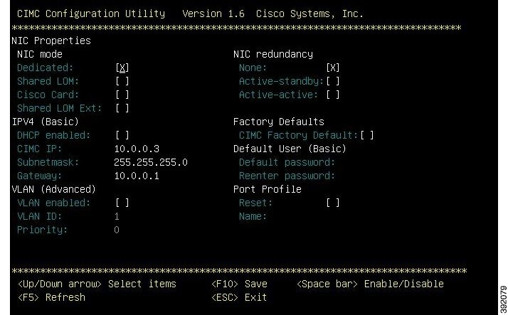 Set the following parameters: Under NIC mode, enable Dedicated. Under IPV4 (Basic), provide values for your network for CIMC IP, Subnetmask, and Gateway. Under NIC Redundancy, enable None. | ||||
| Step 10 | When
completed, select
<ESC> to exit the utility and return to the Cisco
setup menu.
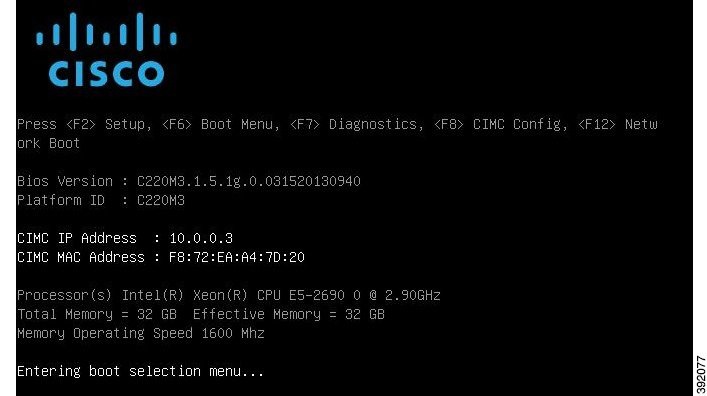 | ||||
| Step 11 | Press
<F6>
to access the Boot Menu. Click the applicable boot device.
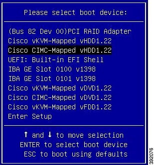 | ||||
| Step 12 | Reboot the
server using the CTRL-ALT-DEL macro as shown.
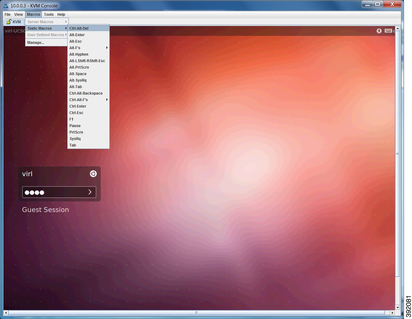 | ||||
| Step 13 | On the
Power
cycle the server? confirmation dialog box, click
OK.
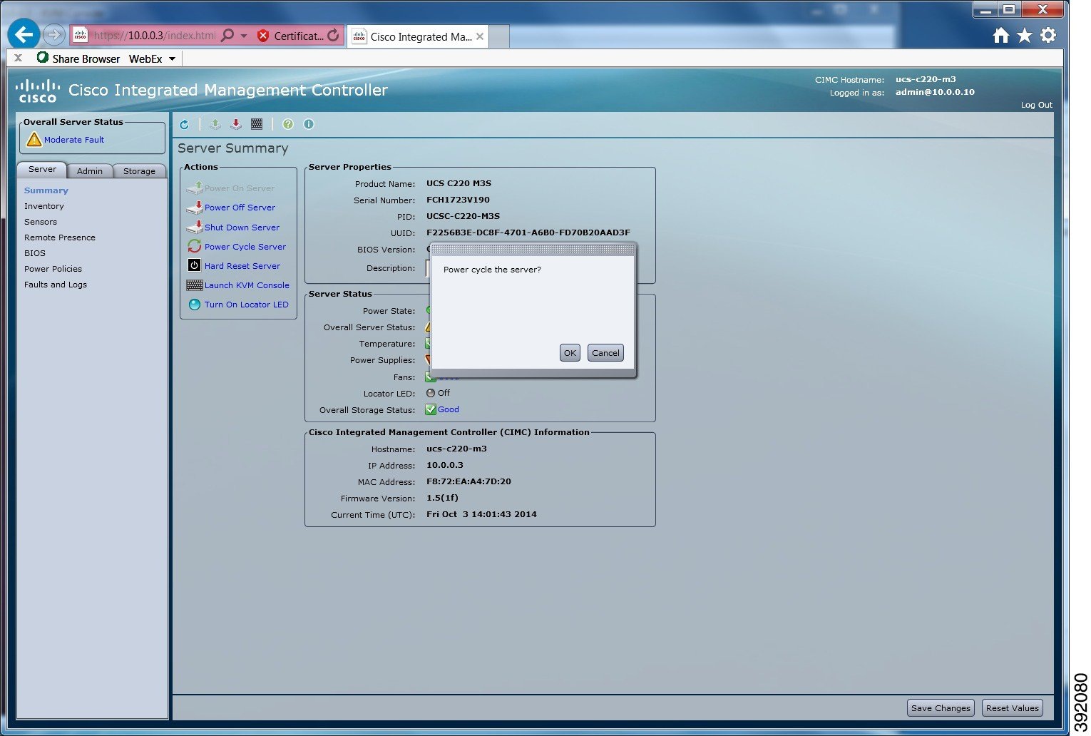 The server boots from the virtual machine and the VIRL Installer window appears. | ||||
| Step 14 | There are
five options available:
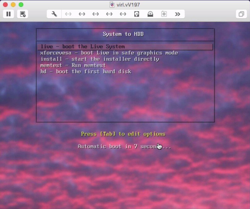
| ||||
| Step 15 | Log into the
virtual machine using username virl and password VIRL.
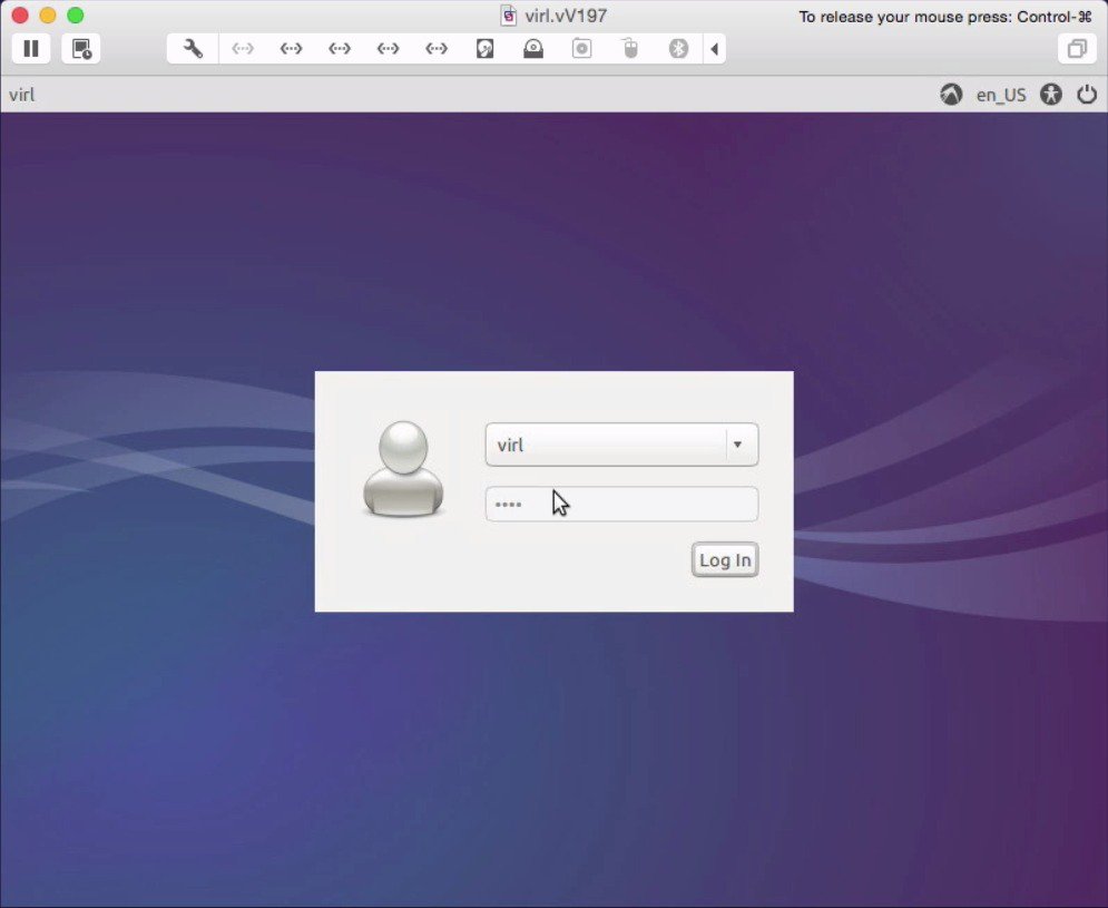 | ||||
| Step 16 | On the
desktop, double-click
Install system
to HDD to begin the installation
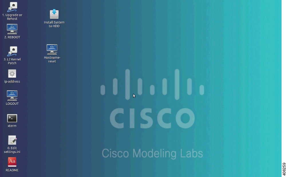
|
Install the Cisco Modeling Labs ISO Disk Image
To install the Cisco Modeling Labs ISO disk image, complete the following steps:
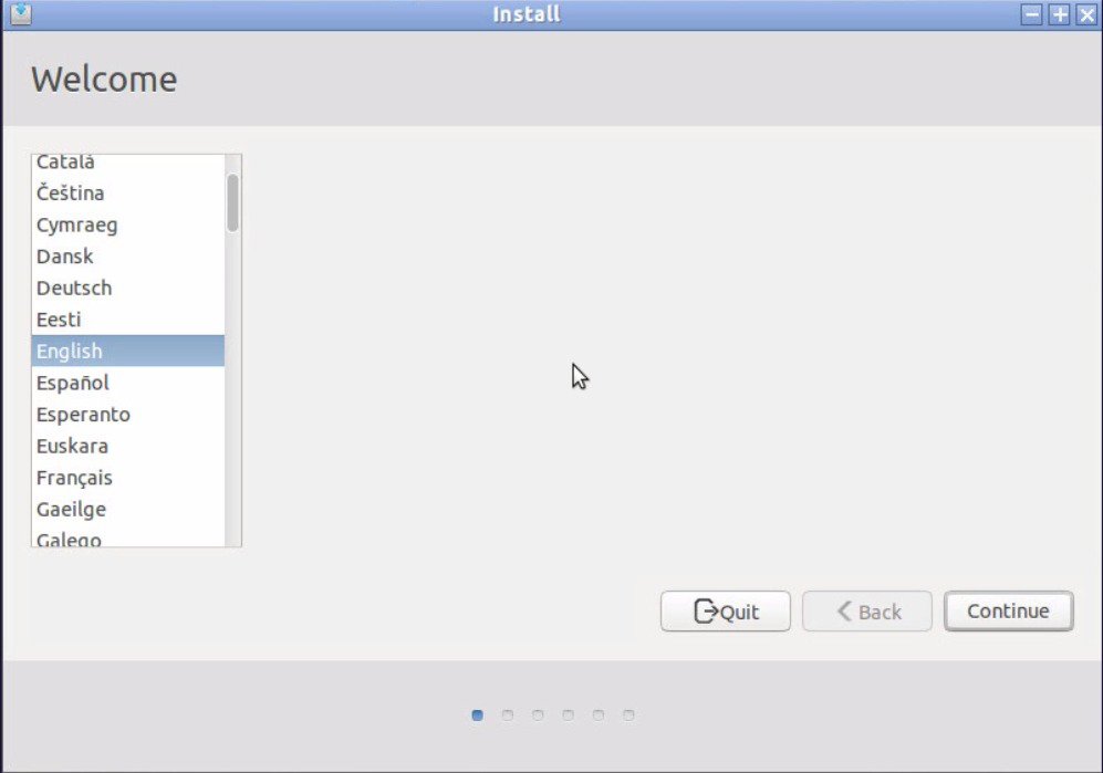
| Step 1 | In the
Welcome window, choose the applicable language and
click
Continue.
 | ||||||
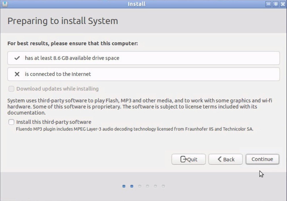
| Step 2 | In the
Preparing
to Install
window, ensure that you have adequate resources to
install the ISO disk image and click
Continue.
 | ||||||
| Step 3 | In the
Installation type window, click the
Erase disk and install
System radio button and check the
Use LVM with the new system
installation check box, to setup Logical Volume Management.
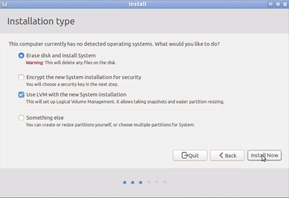 Click Install Now. | ||||||
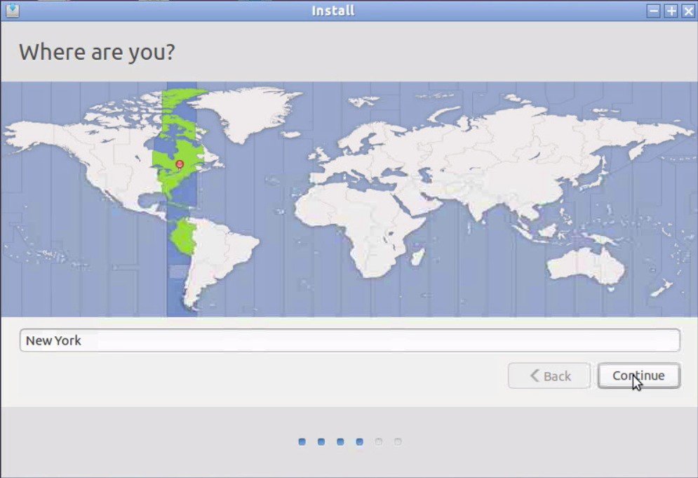
| Step 4 | In the
Where are
you? window, enter the applicable time zone, and click
Continue.
| ||||||
| Step 5 | In the
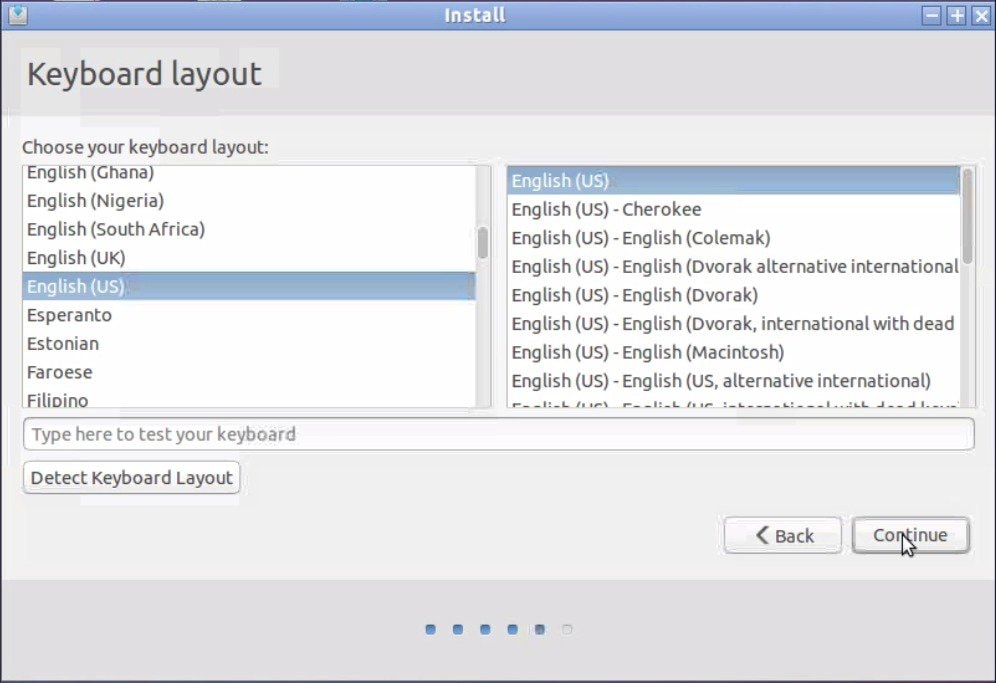
Keyboard
layout window, choose the applicable locale-specific keyboard layout
to use by clicking the corresponding option from the Choose your keyboard
layout list, and click
Continue.
| ||||||
| Step 6 | In the
Who are
you? window, enter values for the fields exactly as described here:
Click Continue to start the installation. 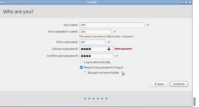
| ||||||
| Step 7 | In the
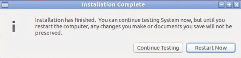
Installation Complete window, click
Restart Now
to restart the server.
 |
(Optional) Prepare for an Interface-Constrained Installation
|
Network Interface |
Description |
|---|---|
|
eth0 |
For management access with an IP address assigned via DHCP or via manual static IP address configuration. |
|
eth1 |
For external layer-2 management and data-plane access (Flat) with a default IP address of 172.16.1.254/24. |
|
eth2 |
For external layer-2 management and data-plane access (Flat1) with a default IP address of 172.16.1.254/24. |
|
eth3 |
For external layer-3 management and data-plane access (SNAT) with a default IP address of 172.16.1.254/24. |
|
eth4 |
To anchor OpenStack services and for inter-host communications with a default IP address of 172.16.10.250/24. |
Whenever the virtual machine is missing one or more of these interfaces, it is necessary to first create an alias for the missing OpenStack services IP address and then create dummy interfaces that can be used by Cisco Modeling Labs in place of the missing interfaces.
The steps described in this section are for a virtual machine with only two network interfaces (eth0 and eth1) available. Therefore, three dummy interfaces (dummy1, dummy2, and dummy3) must be configured.
If in your implementation, your virtual machine has more or less interfaces, adapt the number of required dummy interfaces accordingly. Otherwise, if your virtual machine has the required five network interfaces, skip this section.
| Step 1 | Start the
virtual machine and log in using username virl and password VIRL.
| ||
| Step 2 | Click the xterm icon to open a terminal window. | ||
| Step 3 | Open the network configuration file for editing: sudo nano /etc/network/interfaces | ||
| Step 4 | Add a new line
in the eth0 section and enter
up ip addr
add 172.16.10.250/24 dev eth0 to create a new alias for the missing
OpenStack services address.
For example:
iface eth0 inet dhcp
        dns-nameservers 8.8.8.8 8.8.4.4
        up ip addr add 172.16.10.250/24 dev eth0
| ||
| Step 5 | Enter Ctrl-X to exit nano. | ||
| Step 6 | Enter Y and Enter to confirm saving the network configuration file and exit. | ||
| Step 7 | Open the configuration file for editing: sudo nano /etc/virl.ini | ||
| Step 8 | Change the hostname to ubuntu. This can be modified later during customization if desired. | ||
| Step 9 | Enter Ctrl-W and
search for 'l2_port:'.
| ||
| Step 10 | Enter Ctrl-W and search for 'l2_port2:'. In this example, since interface eth2 is missing, l2_port2: must be mapped to interface dummy1. Replace eth2 with dummy1. | ||
| Step 11 | Enter Ctrl-W and search for 'l3_port:'. In this example, since interface eth3 is missing, l3_port: must be mapped to interface dummy2. Replace eth3 with dummy2. | ||
| Step 12 | Enter Ctrl-W and search for 'internalnet_port:'. In this example, since interface eth4 is missing, internalnet_port: must be mapped to interface dummy3. Replace eth4 with dummy3. | ||
| Step 13 | Enter Ctrl-W and search for 'dummy_int'. Since dummy interfaces are required dummy_int must be set to True. | ||
| Step 14 | Enter Ctrl-X to exit nano. | ||
| Step 15 | Enter Y and Enter to confirm saving the configuration file and exit. | ||
| Step 16 | Enter sudo reboot now to reboot the virtual machine. | ||
| Step 17 | Once rebooted, log in again using username virl and password VIRL. | ||
| Step 18 | Click the xterm icon to open a terminal window. | ||
| Step 19 | Confirm that the
OpenStack services IP address is reachable:
ping -c 4
172.16.10.250
| ||
| Step 20 | Enter
nova
service-list to display the status of the Nova services.
Verify
that the status for each Nova service is enabled and that the state for each is
up.
| ||
| Step 21 | Enter
neutron
agent-list to display the status of the OpenStack Neutron agents.
Verify
that the status for the Metadata, DHCP, and L3 agents is :-).
|
(Optional) Configure Static IP
Where there is no DHCP addressing facility on the subnet to which the Cisco Modeling Labs virtual machine is connected via eth0, it is necessary to assign a static IP address before proceeding.
This section describes the configuration steps to use when Static IP addressing is required. However, if DHCP is being used to configure the eth0 IP address, you may skip this section.
| Step 1 | Start the
virtual machine and log in using the username virl and the password VIRL.
| ||
| Step 2 | Click the xterm icon to open a terminal window. | ||
| Step 3 | Change to the network interfaces configuration directory: cd /etc/network | ||
| Step 4 | Open the interfaces configuration file for editing: sudo nano interfaces | ||
| Step 5 | Change the eth0 addressing method to static: iface eth0 inet static | ||
| Step 6 | Provide the static IP address: address n.n.n.n | ||
| Step 7 | Provide the static IP address netmask: netmask mmm.mmm.mmm.mmm | ||
| Step 8 | Provide the default IP gateway address: gateway g.g.g.g | ||
| Step 9 | Provide valid reachable DNS name-server addresses: dns-nameservers a.a.a.a b.b.b.b | ||
| Step 10 | Enter Ctrl-X to exit. | ||
| Step 11 | Enter Y and Enter to confirm saving the interfaces file and exit. | ||
| Step 12 | Enter sudo reboot now to reboot the virtual machine in preparation for the remaining installation steps. |
(Optional) Configure Internet Proxies
Access to Internet servers is required for the configuration and customization of Cisco Modeling Labs as outlined in this section. If Cisco Modeling Labs is being deployed in a location where proxies are used then they must be configured, as described, using your site-specific parameters. Otherwise, if no proxies are being used, skip this section.
| Step 1 | Start the
virtual machine and log in using the username virl and the password VIRL.
| ||
| Step 2 | Click the xterm icon to open a terminal window. | ||
| Step 3 | Open the file for editing: nano .bashrc | ||
| Step 4 | Add in a number
of new lines, enter a description for the proxy block
# Add proxy
configuration and enter the following:
For example:
export http_proxy=http://proxy.domain.tld:port/
export https_proxy=http://proxy.domain.tld:port/
export HTTP_PROXY=$http_proxy
export HTTPS_PROXY=$https_proxy
| ||
| Step 5 | Enter Ctrl-X to exit nano. | ||
| Step 6 | Enter Y and Enter to confirm saving the .bashrc file and exit. | ||
| Step 7 | Open the file for editing: sudo nano /etc/apt/apt.conf | ||
| Step 8 | Define the proxy
configuration for use by APT:
Acquire::http::proxy "proxy.domain.tld:port/";
| ||
| Step 9 | Enter Ctrl-X to exit nano. | ||
| Step 10 | Enter Y and Enter to confirm saving the apt.conf file and exit. | ||
| Step 11 | Enter exit to close the terminal window, |
Customize the Cisco Modeling Labs Configuration
Many aspects of Cisco Modeling Labs can be customized to suit specific and unique deployment requirements by modifying the configuration settings file (/etc/settings.ini).
-
When using static IP addressing or Internet proxies.
-
When there is a need to connect and integrate the Cisco Modeling Labs Layer 2 or Layer 3 networks with existing external networks.
-
When the virtual machine has >16GB of memory and there is a desire to enable RAMdisk to decrease simulation startup times.
-
When the virtual machine to which Cisco Modeling Labs is being installed has fewer than five network interfaces.
Note | If static IP or Internet proxies were specified in previous sections then they must also be specified during this installation step. |
| Step 1 | Start the
virtual machine and log in using the username virl and the password VIRL.
| ||||
| Step 2 | Click the 0. Edit settings.ini icon. | ||||
| Step 3 | Update the Cisco
Modeling Labs configuration to meet site-specific requirements using the
following configuration statements:
| ||||
| Step 4 | Save the changes to the settings.ini file and exit the editor. | ||||
| Step 5 | On the desktop, click the 1. Upgrade or Rehost icon to start a standard installation process to configure the customizations entered previously. | ||||
| Step 6 | When completed, click the 2. REBOOT icon to reboot the virtual machine. | ||||
| Step 7 | Log in with the username virl and the password VIRL. | ||||
| Step 8 | Enter the command
ifconfig eth0 to view the IP address assigned.
You will use this IP address to access the User Workspace Management interface. |
Determine License Key Requirements
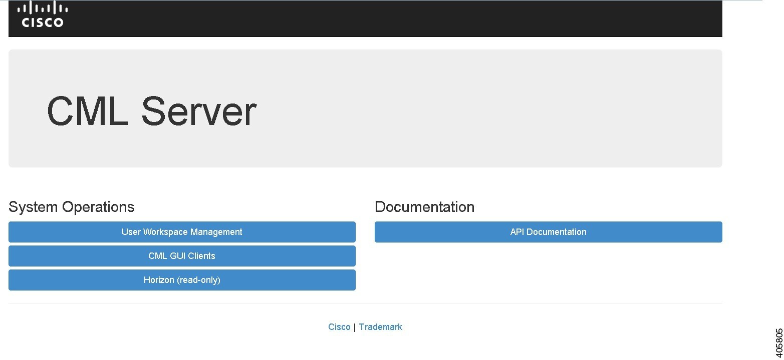
| Step 1 | In a web browser, use the IP address or hostname of your Cisco
Modeling Labs server to access the
CML Server interface, in the format
http://<IP address | hostname>.
| ||||||||
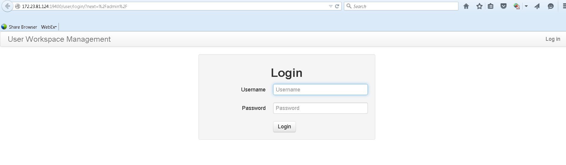
| Step 2 | Click
User Workspace
Management and log in to the interface using the username
uwmadmin and
the password
password and
switch to
Admin mode.
 | ||||||||
| Step 3 | In the left pane, click Licenses. | ||||||||
| Step 4 | In the Licenses page, click Register Licenses. | ||||||||
| Step 5 | Record the
Host Name and
Mac Address for
license key registration.
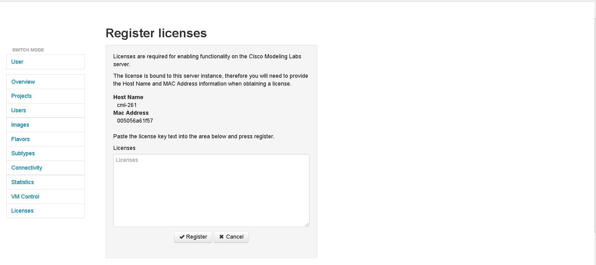 Use this information when completing the Register Claim Certificates instructions in the eDelivery Order Notification email to request your license key for use with the Cisco Modeling Labs server.
You will receive your license key as an attachment via an email. | ||||||||
| Step 6 | Open the attachment in a text editor and copy all the details. | ||||||||
| Step 7 | Return to the Register Licenses page. | ||||||||
| Step 8 | Repeat Step 1 and Step 2, and paste the details into the Licenses text area. | ||||||||
| Step 9 | Click
Register to
register the license key.
| ||||||||
| Step 10 | Click Log Out to exit the User Workspace Management interface. |
 Feedback