Cisco DNA Traffic Telemetry Appliance Overview

This chapter contains information about the Cisco DNA Traffic Telemetry Appliance, and contains the following sections:

Information About the Cisco DNA Traffic Telemetry Appliance

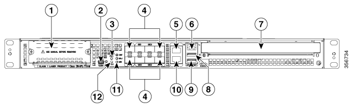
The Cisco DNA Traffic Telemetry Appliance is a telemetry sensor platform that is used to generate telemetry from mirrored IP network traffic and share it with Cisco DNA Center for application and endpoint visibility. Network traffic is received from switches and routers via Switched Port Analyzer (SPAN) mirroring and fed into the Cisco DNA Traffic Telemetry Appliance mirroring interfaces. The Cisco DNA Traffic Telemetry Appliance analyzes the received traffic to produce a telemetry stream for Cisco DNA Center that is sent via the appliance network interface.

The Cisco DNA Traffic Telemetry Appliance offers a compact form factor that consumes less rack space and power.

Table 1. Platform Booting Methods
Boot Method Booting Command from ROMMON Supported in IOS XE 17.3.1

Bin boot

rommon> boot bootflash:ttam-universalk9.*.SSA.bin

Yes

Install boot

rommon> boot bootflash:packages.conf

No


Note

Install boot is not supported in Cisco IOS XE Amsterdam 17.3.1. The impact of this limitation is the boot time: .bin boot takes more time than the Install boot, because the slower ROMMON retrieves the entire ttam-universalk9.*.SSA.bin from the bootflash to the memory.


Hardware Features of the Cisco DNA Traffic Telemetry Appliance

The Cisco DNA Traffic Telemetry Appliance supports these features:

  • Up to 16-GB memory configuration of DDR3 error-correcting code-protected field-replaceable memory, with single-bit error correction and multi-bit error detection

  • RJ-45 console ports and auxiliary ports, and a mini USB console port

  • One copper Ethernet 10/100/1000 Mbps network management port

  • An embedded USB (eUSB) flash module that supports 8 GB of nonvolatile flash storage

  • Two USB 2.0 ports for USB flash sticks or USB secure tokens (secure key distribution)

  • Stratum 3E network clocking per GR-1244-CORE, using 1588, 10 GE, GE, or Network Interface Module (NIM) interfaces as timing sources

  • Six built-in 1-GE SFP-only interfaces (do not support SFP+), and two built-in 10-GE SFP+ interfaces (support only 10-GE rate) that support SyncE

  • Software redundancy using Dual IOS, similar to all other nonhardware telemetry appliances

  • LED indicators for Ethernet and console status, as well as visual system state indications

  • Command-line interface (CLI), alarm, network management, logging, statistics aggregation, and onboard failure logging (OBFL)

  • Environmental chassis management

  • 10 MB ternary content-addressable memory (TCAM)

  • Up to 20 Gbps sustained forwarding data traffic through the chassis

  • One Network Interface Module (NIM) bay

Cisco DNA Traffic Telemetry Appliance Front View

The following figure shows the front of the Cisco DNA Traffic Telemetry Appliance.

Figure 1. Cisco DNA Traffic Telemetry Appliance Front View

1

NIM slots

7

2

CON—One mini eUSB port

8

USB port 0

3

PWR—Power LED

9

USB port 1

4

Six built-in 1 GE SFP-only interfaces (do not support SFP+), and two built-in 10 GE SFP+ interfaces (support only 10-GE rate)

10

CON—One RJ-45/RS-232 compatible console port

5

AUX—One RJ-45/RS-232 compatible auxiliary port

11

CRIT LED—Critical alarm indicator

MAJ LED—Major alarm indicator

MIN LED—Minor alarm indicator

6

MGMT—One RJ-45 10/100/1000 management Ethernet port. The management port has two LEDs, L and S. L green indicates Link operations. S blinks the negotiated Ethernet speed (1 blink equals 10 Mbps, 2 blinks equals 100 Mbps, 3 blinks equals 1 000 Mbps).

12

STAT—Status LED

Cisco DNA Traffic Telemetry Appliance LEDs

The following figure shows the front panel of the Cisco DNA Traffic Telemetry Appliance:

Figure 2. Common LEDs for the Cisco DNA Traffic Telemetry Appliance

No.

LED Label

LED

Color

Behavior in the Power-Up State

1

PWR

Power

Green

All the power supplies are within operational limits.

2

MAJ

MAJOR

Red

Major alarm indicator.

3

CRIT

CRITICAL

Red

Critical alarm indicator. Will be off when the appliance is initially powered up and all the configured components are available.

4

MIN

MINOR

Amber

Minor alarm indicator

5

STAT

STATUS

Green

Cisco IOS has successfully booted.

Yellow

The system is at ROMMON.

Red

System failure. Will be off when the appliance is powered up.

6

EN

USB Console Enable

Green

Indicates that the mini eUSB connector is used as the console.

Off

Indicates that the RJ-45 connector is being used as the console.

Cisco DNA Traffic Telemetry Appliance Management Connections

The following figure shows the Cisco DNA Traffic Telemetry Appliance's management storage connections.

Figure 3. Management Connections for the Cisco DNA Traffic Telemetry Appliance

1

AUX—One RJ-45/RS-232 compatible auxiliary port.

4

USB port 1

2

MGMT —one RJ-45 10/100/1000 management Ethernet port. The Management Port has two LEDs, L and S. L green indicates Link operations. S blinks the negotiated Ethernet speed (1 blink 10 Mbps, 2 blinks 100 Mbps, 3 blinks, 1 000 Mbps).

5

CON—One RJ-45/RS-232 compatible console port

3

USB port 0

Cisco DNA Traffic Telemetry Appliance Rear View

The following figure shows the rear of the Cisco DNA Traffic Telemetry Appliance.

Figure 4. Cisco DNA Traffic Telemetry Appliance Rear View

Four internal fans draw cooling air into the chassis and across internal components to maintain an acceptable operating temperature. The fans are located in the center of the chassis. The fans are numbered from 0 to 3, right to left.

Two power supplies, either two AC power supplies or two DC power supplies, are accessed from the rear of the appliance and are hot-swappable.


Note

The Cisco DNA Traffic Telemetry Appliance can support two AC or two DC power supplies. Do not install mixed AC and DC power supply units in the same chassis.

Cisco DNA Traffic Telemetry Appliance GE Ports

The 8-GE SFP+ ports are indicated in the front bezel with orange highlights, and the GE SFP ports are indicated with yellow highlights. The following figure shows the port numbering.

Figure 5. GE Port Numbering

1

8 GE SFP+ Port 0/0/0

5

GE SFP Port 0/0/2

2

8 GE SFP+ Port 0/0/1

6

GE SFP Port 0/0/3

3

GE SFP Port 0/0/0

7

GE SFP Port 0/0/4

4

GE SFP Port 0/0/1

8

GE SFP Port 0/0/5

Field-Replaceable Units for the Cisco DNA Traffic Telemetry Appliance

The Cisco DNA Traffic Telemetry Appliance has a number of FRUs. These include:

  • Dual In-line Memory Modules (DIMMs)

  • NIMs

  • SSD and SSD NIM assembly

  • USB flash or secure token memory stick

  • AC and DC power supplies

For more information, see the Removing and Replacing FRUs section.

Cisco Product Identification Standard

This section describes the Cisco products and services product identification standard. This feature provides you with the ability to effectively integrate and manage Cisco products in your network and business operations.

Unique Device Identifier

The Unique Device Identifier (UDI) is the Cisco product identification standard for hardware products. A product identification standard removes barriers to enterprise automation and can help you reduce operating expenses.

The UDI provides a consistent electronic, physical, and associated business-to-business information product identification standard.

The UDI is a combination of the data elements shown in the following table.

Table 2. UDI Elements

UDI Data Element

Electronic Visibility

Physical Visibility

Description

PID

Yes

Yes

Product ID, also known as product name, model name, product number

VID

Yes

Yes

Version ID

SN

Yes

Yes

Serial number, the unique instance of the PID

Entity Name

Yes

Type, such as chassis, slot, or power supply

Product Description

Yes

Additional product information

The combination of serial number and product ID (PID) is unique and consistent across all Cisco products. The PID that is coded on hardware is called a base product identifier.

Additional orderable PIDs can be associated to a base PID. For instance, an orderable PID may describe a packaging configuration for a product or a bundled group of products sold, tested, and shipped together. Specific unique device identifier (UDI) benefits include the following:

  • Identifies:

    • Individual Cisco products in your networks

    • PIDs and serial numbers for service and replaceable products

    • Version IDs (VIDs) for product version visibility

  • Facilitates discovery of products subject to recall or upgrade

  • Enhances inventory automation of Cisco products

The Cisco product identification standard provides the following features:

  • Version visibility: Cisco continuously improves products through feature additions. Product changes are indicated by incrementing the VID, which provides version visibility to help you understand and manage product changes. VID management ensures consistency of changes from product to product.

  • Operating expense reduction: Cisco UDIs provide accurate and detailed network inventory information; identifying each Cisco product in a network element through a standard interface. Cisco operating systems can view and use this data, allowing you to automate your electronic inventory.

  • Consistency across product layers: The UDIs are embedded in the hardware products and cannot be overwritten. Operating and management systems discover UDIs through standard interfaces and display UDIs in standard outputs. Standard interfaces include the IETF standard ENTITY-MIB.

The show diag subslot eeprom command displays the PID, VID, PCB serial number, hardware revision, and other such information.

The following is sample output from the show diag subslot eeprom command:


Device# show diag subslot 0/0 eeprom
MIDPLANE EEPROM data:
        Product Identifier (PID) : DN-APL-TTA-M
        Version Identifier (VID) : V00
        PCB Serial Number        : JAE17450EUV
        Top Assy. Part Number    : 68-4703-06
        Hardware Revision        : 0.1
        Asset ID                 :
        CLEI Code                : CMMP410DRA

Note

Common Language Equipment Identification (CLEI) code is a ten-digit character code that identifies a specific product. A CLEI code is applied to each part within a Cisco DNA Traffic Telemetry Appliance as they are programmed in manufacturing for shipment to customers.

The show license udi command displays UDI information.

The following is sample output from the show license udi command:


Device# show license udi
SlotID   PID                    	SN                      UDI
--------------------------------------------------------------------------------
*6       DN-APL-TTA-M             JAE17190302     DN-APL-TTA-M:JAE17190302

Note

For complete information on the product identification standard, see http://www.cisco.com/go/udi/.

Serial Number and PID/VID Label Location

The following figure shows a Cisco DNA Traffic Telemetry Appliance chassis along with the location of the serial number and the PID/VID label.

Figure 6. Cisco DNA Traffic Telemetry Appliance Serial Number and PID/VID Label Location