Removing and Replacing the Cisco DNA Traffic Telemetry Appliance Power Supplies
The following sections describes the procedures for removing and replacing the Cisco DNA Traffic Telemetry Appliance power supplies.
 Note |
The Cisco DNA Traffic Telemetry Appliance has redundant power supplies that can be hot-swapped. |
DANGER |
The covers are an integral part of the safety design of the product. Do not operate the unit without the covers installed. Statement 1077 |
DANGER |
When you install the unit, the ground connection must always be made first and disconnected last. Statement 1046 |
DANGER |
Before performing any of the following procedures, ensure that power is removed from the DC circuit. Statement 1003 |
DANGER |
Only trained and qualified personnel should be allowed to install, replace, or service this equipment. Statement 1030 |
Removing AC Power Supplies from the Cisco DNA Traffic Telemetry Appliance
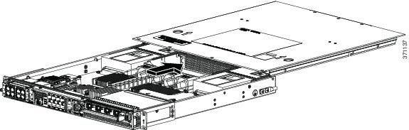
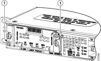
This section describes how to remove an AC power supply from the Cisco DNA Traffic Telemetry Appliance. The appliance has two power supply slots, power supply slot 0 (PS0) next to the Standby switch and power supply slot 1 (PS1) to the right, as shown in the following figures.
Note |
The appliance has redundant power supplies that can be hot-swapped. |
Follow these steps to remove an AC power supply from the appliance:
Procedure
| Step 1 |
At the rear of the appliance, ensure that the power switch is in the Standby position.
|
||
| Step 2 |
Unplug the power cable from the power supply as shown in the following figure. |
||
| Step 3 |
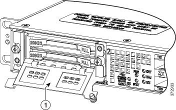
Press the retaining latch towards the pull handle, grasp the handle with one hand, and pull the power supply out of the slot while supporting the weight of the power supply with the other hand, as shown in the following figure. 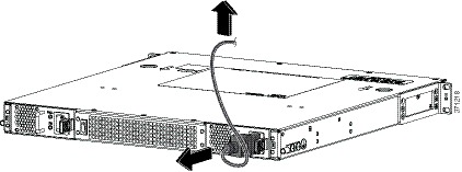
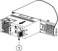
|
||
| Step 4 |
Repeat these steps if you want to remove the other AC power supply. |
What to do next
This completes the procedure for removing the AC power supplies from the Cisco DNA Traffic Telemetry Appliance.
Installing AC Power Supplies in the Cisco DNA Traffic Telemetry Appliance
Note |
Do not install the power supplies with the chassis cover off. |
Follow these steps to install AC power supplies in the Cisco DNA Traffic Telemetry Appliance.
Procedure
| Step 1 |
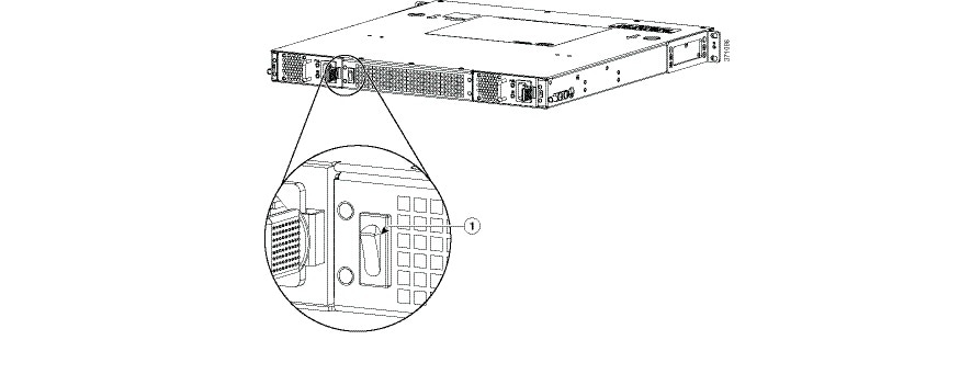
At the rear of the chassis, ensure that the power switch on the chassis is in the Standby position. The following figure shows the AC power supply Standby switch.
|
||||
| Step 2 |
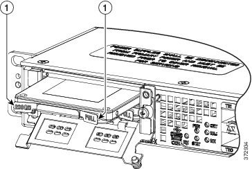
Insert the power supply module into the appropriate slot(s), making sure that the retention latch is firmly placed. You can verify that the power supply module is firmly latched by gently pulling the power supply handle. |
||||
| Step 3 |
Insert the power supply cables firmly into the power supplies.
|
||||
| Step 4 |
Ensure that the AC power cords are positioned, as shown in the following figure. 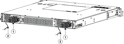
|
||||
| Step 5 |
If you have changed the Standby switch to the standby position in step 1, turn the Standby switch to the On position. The power supply LEDs are illuminated (green). |
What to do next
This completes the procedure for connecting AC input power.
Removing DC Input Power from the Cisco DNA Traffic Telemetry Appliance
Note |
The appliance has redundant power supplies that can be hot-swapped. |
Follow these steps to remove a DC power supply from the Cisco DNA Traffic Telemetry Appliance.
Procedure
| Step 1 |
Turn off the circuit breaker from the power source. |
||
| Step 2 |
At the rear of the appliance, ensure that the power switch is in the Standby position.
|
||
| Step 3 |
Unscrew the two terminal block wire connectors (negative and positive) on the unit. See the following figure. |
||
| Step 4 |
Press the retaining latch towards the pull handle, grasp the handle with one hand, and pull the power supply out of the slot while supporting the weight of the power supply with the other hand. See the following figure. 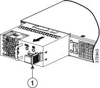
|
Installing DC Input Power on the Cisco DNA Traffic Telemetry Appliance
DANGER |
Before performing any of the following procedures, ensure that power is removed from the DC circuit. Statement 1003 |
DANGER |
Only trained and qualified personnel should be allowed to install, replace, or service this equipment. Statement 1030 |
This section describes how to install the DC power supply input power leads to the Cisco DNA Traffic Telemetry Appliance DC input power supply. Before you begin, read these important notices:
-
The color coding of the DC input power supply leads depends on the color coding of the DC power source at your site. Ensure that the lead color coding you choose for the DC input power supply matches the lead color coding used at the DC power source and verify that the power source is connected to the negative (–) terminal and to the positive (+) terminal on the power supply.
-
Ensure that the chassis ground is connected on the chassis before you begin installing the DC power supply. See Attaching a Chassis Ground Connection.
Wiring the DC Input Power Source
The Cisco DNA Traffic Telemetry Appliance DC power supply has a terminal block that is installed into the power supply terminal block header.
Use the following steps to wire the DC input power source:
Procedure
| Step 1 |
Turn off the circuit breaker from the power source. |
||||
| Step 2 |
At the rear of the appliance, ensure that the power switch is in the Standby position.
|
||||
| Step 3 |
Use a wire-stripping tool to strip each of the two wires coming from the DC input power source and strip the wires to approximately 0.39 inch (10 mm) + 0.02 inch (0.5 mm). Do not strip more than the recommended length of wire because doing so could leave the wire exposed from the terminal block. The following figure shows a stripped DC input power source wire. 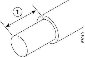
|
||||
| Step 4 |
Identify the positive and negative feed positions for the terminal block connection. The wiring sequence is:
|
||||
| Step 5 |
Insert the exposed wire into the terminal block. Ensure that you cannot see any wire lead outside the plastic cover. Only wires with insulation should extend from the terminal block.
|
||||
| Step 6 |
Use a screwdriver to tighten the terminal block captive screws, as shown in the following figure. 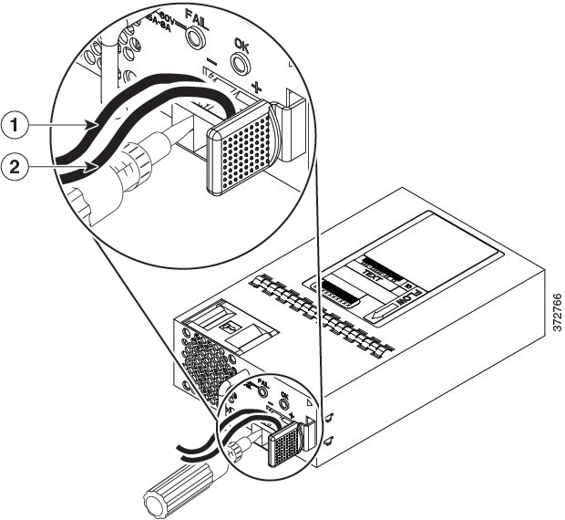
|
||||
| Step 7 |
Repeat these steps for the remaining DC input power source wire as applicable. |
||||
| Step 8 |
Use a tie wrap to secure the wires to the rack, so that the wires are not pulled from the terminal block by casual contact. |
||||
| Step 9 |
Turn on the circuit breaker at the power source. |
||||
| Step 10 |
If you have changed the Standby switch to the standby position in step 1, turn the Standby switch to the On position. The power supply LEDs illuminate green. |
What to do next
This completes the procedure for connecting the DC power supply in the Cisco DNA Traffic Telemetry Appliance.


 Feedback