Configure System Settings

About System Settings

To start using Cisco DNA Center, you must first configure the system settings so that the server can communicate outside the network, ensure secure communications, authenticate users, and perform other key tasks. Use the procedures described in this chapter to configure the system settings.


Note


  • Any changes that you make to the Cisco DNA Center configuration—including changes to the proxy server settings—must be done from the Cisco DNA Center GUI.

  • Any changes to the IP address, static route, DNS server, or maglev user password must be done from the CLI with the sudo maglev-config update command.

  • By default, the Cisco DNA Center system time zone is set to UTC. Do not change this time zone in settings because the Cisco DNA Center GUI works with your browser time zone.


User Profile Roles and Permissions

Cisco DNA Center supports role-based access control (RBAC). The roles assigned to a user profile define the capabilities that a user has permission to perform. Cisco DNA Center has three main default user roles:

  • SUPER-ADMIN-ROLE

  • NETWORK-ADMIN-ROLE

  • OBSERVER-ROLE

The SUPER-ADMIN-ROLE gives users broad capabilities and permits them to perform all actions in the Cisco DNA Center GUI, including creating custom roles and assigning them to user profiles. The NETWORK-ADMIN-ROLE and the OBSERVER-ROLE have more limited and restricted capabilities in the Cisco DNA Center GUI.

If you’re unable to perform an action in Cisco DNA Center, the reason might be that your user profile is assigned a role that doesn’t permit it. For more information, check with your system administrator or see Configure Role-Based Access Control.

Use System 360

The System 360 tab provides at-a-glance information about Cisco DNA Center.

Procedure


Step 1

Click the menu icon () and choose System > System 360.

Step 2

On the System 360 dashboard, review the following displayed data metrics:

Cluster

  • Hosts: Displays information about the Cisco DNA Center hosts. The information that is displayed includes the IP address of the hosts and detailed data about the services running on the hosts. Click the View Services link to view detailed data about the services running on the hosts.

    Note


    The host IP address has a color badge next to it. A green badge indicates that the host is healthy. A red badge indicates that the host is unhealthy.

    The side panel displays the following information:

    • Node Status: Displays the health status of the node.

      If the node health is unhealthy, hover over the status to view additional information for troubleshooting.

    • Services Status: Displays the health status of the services. Even if one service is down, the status is Unhealthy.

    • Name: Service name.

    • Appstack: App stack name.

      An app stack is a loosely coupled collection of services. A service in this environment is a horizontally scalable application that adds instances of itself when demand increases, and frees instances of itself when demand decreases.

    • Health: Status of the service.

    • Version: Version of the service.

    • Tools: Displays metrics and logs for the service. Click the Metrics link to view service monitoring data in Grafana. Grafana is an open-source metric analytics and visualization suite. You can troubleshoot issues by reviewing the service monitoring data. For information about Grafana, see https://grafana.com/. Click the Logs link to view service logs in Kibana. Kibana is an open-source analytics and visualization platform. You can troubleshoot issues by reviewing the service logs. For information about Kibana, see https://www.elastic.co/products/kibana.

  • High Availability: Displays whether HA is enabled and active.

    Important


    Three or more hosts are required for HA to work in Cisco DNA Center.

  • Cluster Tools: Lets you access the following tools:

    • Service Explorer: Access the app stack and the associated services.

    • Monitoring: Access multiple dashboards of Cisco DNA Center components using Grafana, which is an open-source metric analytics and visualization suite. Use the Monitoring tool to review and analyze key Cisco DNA Center metrics, such as memory and CPU usage. For information about Grafana, see https://grafana.com/.

      Note


      In a multihost Cisco DNA Center environment, expect duplication in the Grafana data due to the multiple hosts.

    • Log Explorer: Access Cisco DNA Center activity and system logs using Kibana. Kibana is an open-source analytics and visualization platform designed to work with Elasticsearch. Use the Log Explorer tool to review detailed activity and system logs. In the Kibana left navigation pane, click Dashboard. Then, click System Overview and view all of the system logs. For information about Kibana, see https://www.elastic.co/products/kibana.

      Note


      All logging in Cisco DNA Center is enabled, by default.

System Management

  • Software Updates: Displays the status of application or system updates. Click the View link to view the update details.

    Note


    An update has a color badge next to it. A green badge indicates that the update or actions related to the update succeeded. A yellow badge indicates that there is an available update.

  • Backups: Displays the status of the most recent backup. Click the View link to view all backup details.

    Additionally, it displays the status of the next scheduled backup (or indicates that no backup is scheduled).

    Note


    A backup has a color badge next to it. A green badge indicates a successful backup with a timestamp. A yellow badge indicates that the next backup is not yet scheduled.

  • Application Health: Displays the health of automation and Assurance.

    Note


    Application health has a color badge next to it. A green badge indicates a healthy application. A red badge indicates that the application is unhealthy. Click the View link to troubleshoot.

Externally Connected Systems

Displays information about external network services used by Cisco DNA Center.

  • Identity Services Engine (ISE): Displays Cisco ISE configuration data, including the IP address and status of the primary and secondary Cisco ISE servers. Click the Configure link to configure Cisco DNA Center for integration with Cisco ISE.

  • IP Address Manager (IPAM): Displays IP address manager configuration data and the integration status. Click the Configure link to configure the IP Address Manager.

  • vManage: Displays vManage configuration data. Click the Configure link to configure vManage.


View the Services in System 360

The System 360 tab provides detailed information about the app stacks and services running on Cisco DNA Center. You can use this information to assist in troubleshooting issues with specific applications or services. For example, if you are having issues with Assurance, you can view monitoring data and logs for the NDP app stack and its component services.

Procedure


Step 1

Click the menu icon () and choose System > System 360.

Step 2

In System 360 window, click Service Explorer tab.

The node clusters and the associated services are displayed in a tree-like structure in a new browser window.
  • Hover your cursor over the node to view the details like, serial number, product ID, and interface.

  • The Services table shows all the services associated with the node. The managed services are marked as (M).

  • In the Service table, click the global filter icon to filter services by app stack name, service health status (Up, Down, or In Progress), or managed services.

  • Enter a service name in the Global Search field to find a service. Click the service name to view the service in its associated node.

Step 3

Click the service to launch the Service 360 view, which displays the following details:

  • Metrics: Click the link to view the services monitoring data in Grafana.

  • Logs: Click the link to view the service logs in Kibana.

  • Name: Service name.

  • Appstack: App stack name.

  • Version: Version of the service.

  • Health: Status of the service.

  • Required Healthy Instances: Shows the number of healthy instances and indicates whether the service is managed.

  • Instances: Click the instances to view details.

Step 4

Enter the service name in the Search field to search the services listed in the table.

Step 5

Click the filter icon in the services table to filter services based on app stack name, service status (Up, Down, or In Progress), or managed service.


Monitor System Health

From the System Health page, you can monitor the health of the physical components on your Cisco DNA Center appliances and keep tabs on any issues that may occur. Refer to the following topics, which describe how to enable this functionality and use it in your production environment.

Establish Cisco IMC Connectivity

To enable the System Health page, you must establish connectivity with Cisco Integrated Management Controller (Cisco IMC), which collects health information for your appliances' hardware. Complete the following procedure to do so.


Note


Only users with SUPER-ADMIN-ROLE permissions can enter Cisco IMC connectivity settings for an appliance.

Procedure


Step 1

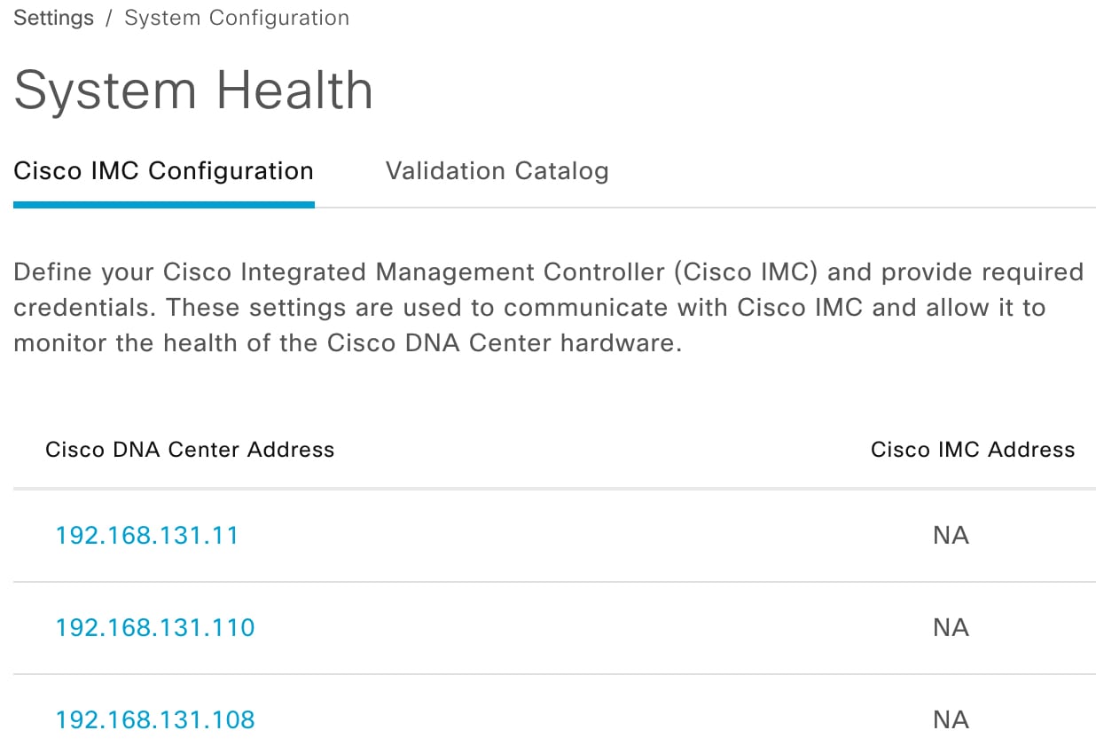
Click the menu icon () and choose System > Settings > System Configuration > System Health.

The IP address of each appliance in your cluster is listed in the Cisco DNA Center Address column.

Step 2

Configure the information required to log in to Cisco IMC:

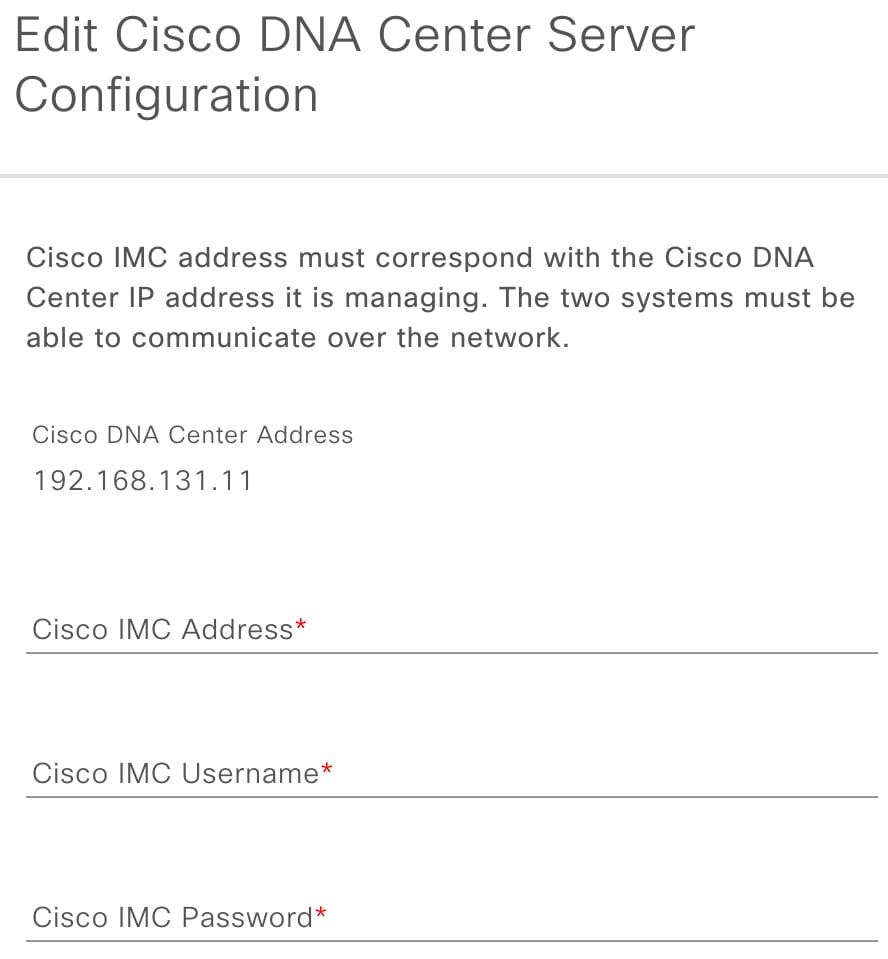
  1. Click the IP address for an appliance.

    The Edit Cisco DNA Center Server Configuration slide-in pane opens.

  2. Enter the following information and then click Save:

    • The IP address configured for the appliance's Cisco IMC port.

    • The username and password required to log in to Cisco IMC.

  3. Repeat this step for the other appliances in your cluster, if necessary.


Delete Cisco IMC Settings

To delete the Cisco IMC connectivity settings that have been configured previously for a particular appliance, complete the following procedure.


Note


Only users with SUPER-ADMIN-ROLE permissions can delete these settings.
Procedure

Step 1

Click the menu icon () and choose System > Settings > System Configuration > System Health.

Step 2

For the appliance for which you want to delete the settings, click the corresponding delete icon () in the Actions column.

Step 3

In the confirmation window, click Ok.


Subscribe to System Event Notifications

Information about system event notifications.

After you have established connectivity with Cisco IMC, Cisco DNA Center collects event information from Cisco IMC and stores this information as raw system events. The rules engine then processes these raw events and converts them into system event notifications that are displayed in the System Health topology. By completing the procedure described in the "Work with Event Notifications" topic of the Cisco DNA Center Platform User Guide, you can also receive these notifications in one of the available formats. When completing this procedure, select and subscribe to the following events:

  • Certificate expiration events:

    • SYSTEM-CERTIFICATE

    • SYSTEM-NODE-CERTIFICATE

  • Connected external systems events:

    • SYSTEM-EXTERNAL-CMX

    • SYSTEM-EXTERNAL-IPAM

    • SYSTEM-EXTERNAL-ISE-AAA-TRUST

    • SYSTEM-EXTERNAL-ISE-PAN-ERS

    • SYSTEM-EXTERNAL-ISE-PXGRID

    • SYSTEM-EXTERNAL-ITSM

  • Disaster recovery system events: SYSTEM-DISASTER-RECOVERY

  • General system events:

    • SYSTEM-CIMC

    • SYSTEM-CONFIGURATION

    • SYSTEM-HARDWARE

    • SYSTEM-MANAGED-SERVICES


      Note


      For managed services, the probe interval (the time it takes for Cisco DNA Center to delete stale events from its database) is 60 minutes. When managed services have been down and become active again, it takes this long for the System Health GUI to reflect that the services have been restored.


    • SYSTEM-SCALE-LIMITS

Event Notification Information

The following table lists the key information that Cisco DNA Center provides when it generates a system health notification message.

Subdomain Tag Instance State Message

Domain: System

CPU CPU <node-hostname>:CPU-1 OK

Cisco DNA Center CPU-1 is working as expected on <node-hostname>

NotOk Cisco DNA Center CPU-1 has failed on <node-hostname>
Disabled Cisco DNA Center CPU-1 is disabled on <node-hostname>
Memory Memory <node-hostname>:DIMM_A1 Ok Cisco DNA Center RAM DIMM_A1 is working as expected on <node-hostname>
NotOk Cisco DNA Center RAM DIMM_A1 has failed on <node-hostname>
Disk Disk <node-hostname>:Disk1 Ok Cisco DNA Center Disk 2 is working as expected on <node-hostname>
NotOk Cisco DNA Center Disk 2 has failed on <node-hostname>
RAID Controller RAIDController <node-hostname>:Controller-1 Ok Cisco DNA Center RAID VD-2 is working as expected on <node-hostname>
NotOk Cisco DNA Center RAID VD-2 has degraded on <node-hostname>
Disabled Cisco DNA Center RAID VD-2 is offline on <node-hostname>
Network Interfaces NIC <node-hostname>:nic-1 Ok Cisco DNA Center network interfaces are working as expected
NotOk Cisco DNA Center: <x> network interfaces are missing for <node-hostname>: nic-1
PSU_FAN PSU <node-hostname>:psu-1 Ok Cisco DNA Center power supply (PSU-1) is powered on and thermal condition is normal for <node-hostname>
NotOk Cisco DNA Center power supply (PSU-2) is powered off and thermal condition is critical for <node-hostname>
Disaster Recovery DisasterRecovery <disaster-recovery-hostname> Ok
  • Disaster recovery cluster is up

  • Disaster recovery failover succeeded to <site-name>

Degraded
  • Disaster recovery failover triggered from <site-name> to site-name

  • Disaster recovery failed while failing over to <site-name>

  • Disaster recovery standby cluster on <site-name> is down; cannot failover

  • Disaster recovery witness is down; cannot failover

  • Disaster recovery replication halted; recovery point objective will be impacted

  • Disaster recovery pause failed

  • Disaster recovery route advertisement failed

  • Disaster recovery IPSec communication failed

NotOk
  • Disaster recovery configuration failed

  • Disaster recovery failed to rejoin the standby system

Platform Services ManagedServices <hostname>:<name> OK

Managed Service <service-name> is Running

NOTOK

Managed Service <service-name> is Interrupted

Scale Limits wired_concurrent_clients <hostname>:<name> OK OK
NOTOK The number of concurrent wired clients exceeded 26250 (105% of limit)
DEGRADED The number of concurrent wired clients exceeded 21250 (85% of limit)
CAUTION The number of concurrent wired clients exceeded 18750 (75% of limit)
wireless_concurrent_clients <hostname>:<name> OK OK
NOTOK The number of concurrent wireless clients exceeded 18750 (75% of limit)
DEGRADED The number of concurrent wireless clients exceeded 21250 (85% of limit)
CAUTION The number of concurrent wireless clients exceeded 18750 (75% of limit)
wired_devices <hostname>:<name> OK OK
NOTOK The number of wired devices exceeded 1050 (105% of limit)
DEGRADED The number of wired devices exceeded 850 (85% of limit)
CAUTION The number of wired Devices exceeded 750 (75% of limit)
wireless_devices <hostname>:<name> OK OK
NOTOK The number of wireless devices exceeded 3800 (105% of limit)
DEGRADED The number of wireless devices exceeded 3400 (85% of limit)
CAUTION The number of wireless devices exceeded 3000 (75% of limit)
interfaces <hostname>:<name> OK OK
NOTOK The number of interfaces exceeded 1140000000 (95% of limit)
DEGRADED The number of interfaces exceeded 1020000000 (85% of limit)
CAUTION The number of interfaces exceeded 900000000 (75% of limit)
ippools <hostname>:<name> OK OK
NOTOK The number of IP pools exceeded 47500 (95% of limit)
DEGRADED The number of IP pools exceeded 42500 (85% of limit)
CAUTION The number of IP pools exceeded 37500 (75% of limit)
netflows <hostname>:<name> OK OK
NOTOK The number of Netflows exceeded 37500 (75% of limit)
DEGRADED The number of Netflows exceeded xxx (x% of limit)
CAUTION The number of Netflows exceeded yyy (y% of limit)

physical_ports

<hostname>:<name> OK OK
NOTOK The number of physical ports exceeded 50400 (95% of limit)
DEGRADED The number of physical ports exceeded 40800 (85% of limit)
CAUTION The number of physical ports exceeded 36000 (75% of limit)
policy <hostname>:<name> OK OK
NOTOK The number of policies exceeded 23750 (95% of limit)
DEGRADED The number of policies exceeded 21250 (85% of limit)
CAUTION The number of policies exceeded 18750 (75% of limit)
security_group <hostname>:<name> OK OK
NOTOK The number of security groups exceeded 3800 (95% of limit)
DEGRADED The number of security groups exceeded 3400 (85% of limit)
CAUTION The number of security groups exceeded 3000 (75% of limit)
sites <hostname>:<name> OK OK
NOTOK The number of sites exceeded 475 (95% of limit)
DEGRADED The number of sites exceeded 425 (85% of limit)
CAUTION The number of sites exceeded 375 (75% of limit)
transient_clients <hostname>:<name> OK OK
NOTOK The number of transient clients exceeded 71250 (95% of limit)
DEGRADED The number of transient clients exceeded 63750 (85% of limit)
CAUTION The number of transient clients exceeded 56250 (75% of limit)
Software Upgrade Upgrade <hostname>:<name> OK Successfully finished downloading package <package-name> with version <package-version>
NOTOK Catalog package download failed for <package-name>
Backup Backup <hostname>:<name> OK Successfully completed backup

NOTOK

Failed to backup
Restore Restore <hostname>:<name> OK Successfully restored
NOTOK Failed to restore configuration

Domain: Connectivity

ISE ISE_ERS <Cisco-ISE-hostname> Success ISE AAA trust establishment succeeded for ISE server <ISE-server-details>
Failed ISE AAA trust establishment failed for ISE server <ISE-server-details>

Domain: Integrations

IPAM IPAM <IPAM-hostname> Ok IPAM connection to Cisco DNA Center established. IPAM <IPAM-IP-address>.
Critical IPAM connection to Cisco DNA Center offline. IPAM <IPAM-IP-address>.
ISE ISE_AAA <Cisco-ISE-hostname> Up ISE AAA trust establishment succeeded for ISE server. ISE <ISE-IP-address>
Down ISE AAA trust establishment failed for ISE server. ISE <ISE-IP-address>
CMX CMX <CMX-hostname> serviceAvailable CMX connection to Cisco DNA Center offline. CMX <CMX-IP-address>.
serviceNotAvailable CMX connection to Cisco DNA Center offline. CMX <CMX-IP-address>.
ITSM ITSM <ITSM-hostname> Up ITSM connection to Cisco DNA Center offline. ITSM <ITSM-IP-address>.
Down ITSM connection to Cisco DNA Center offline. ITSM <ITSM-IP-address>.

System Health Scale Numbers

The following versions of the second-generation Cisco DNA Center appliance are available:

  • 44-core appliance: Cisco part number DN2-HW-APL

  • 44-core promotional appliance: Cisco part number DN2-HW-APL-U

  • 56-core appliance: Cisco part number DN2-HW-APL-L

  • 56-core promotional appliance: Cisco part number DN2-HW-APL-L-U

  • 112-core appliance: Cisco part number DN2-HW-APL-XL

  • 112-core promotional appliance: Cisco part number DN2-HW-APL-XL-U

System Health monitors these appliances and generates a notification whenever a network component listed in the following table exceeds a particular threshold. The priority of the notification that is generated depends on the percentage of a threshold that has been measured:

  • When 75% of a threshold has been exceeded, an information (P3) notification is generated.

  • When 85% of a threshold has been exceeded, a warning (P2) notification is generated.

  • When 95% of a threshold has been exceeded, a critical (P1) notification is generated.


Note


  • 1,000,000 notifications are maintained in the audit log for every appliance (regardless of type) and are stored for one year.

  • To view the current appliance scale numbers, see the Cisco DNA Center Data Sheet.

  • System Health isn’t supported on Cisco DNA Center clusters consisting of three 44-core appliances.


View the System Topology

From the System Health page's topology, you can view a graphical representation of your Cisco DNA Center appliances and the external systems that are connected to your network, such as Cisco Connected Mobile Experiences (Cisco CMX) and Cisco Identity Services Engine (Cisco ISE). Here, you can quickly identify any network components that are experiencing an issue and require further attention. To populate this page with appliance and external system data, you must first complete the tasks described in the following topics:

To view this page, click the menu icon () in the Cisco DNA Center GUI and choose System > System Health. Topology data is polled every 30 seconds. If any new data is received, the topology automatically updates to reflect this data.

Note the following:

  • Cisco DNA Center now supports IPv6. When viewing a cluster on which IPv6 is enabled, the topology also displays the following information for that cluster's Enterprise virtual IP address:

    • Pre field: 16-bit prefix

    • GID field: 32-bit global ID

    • Subnet field: 16-bit subnet value

    The remainder of the cluster's Enterprise virtual IP address is used to label its topology icon.

  • An IPv6-enabled cluster can only connect to and retrieve data from external systems that also support IPv6.

  • Whenever a connected appliance or external system has a certificate installed that is set to expire, the topology does the following:

    • If a certificate is set to expire within 90 days, the topology displays a warning.

    • If a certificate is set to expire within 30 days, the topology displays an error to bring your attention to the issue.

  • System Health runs a hardware compliance check regularly and indicates whenever a connected appliance or external system does not meet the minimum configuration requirements. For example, System Health updates the topology to indicate when the Write Through cache write policy is not set for a connected virtual drive.

  • If disaster recovery is operational in your production environment, System Health now provides hardware information for the appliances at both the main and recovery site. Previously, hardware information was provided only for main site appliances.

Troubleshoot Appliance and External System Issues

When viewing the System Health topology, the minor issue icon () and major issue icon () indicate network components that require attention. To begin troubleshooting the issue that a component is experiencing, place your cursor over its topology icon to open a pop-up window that displays the following information:

  • A timestamp that indicates when the issue was detected.

  • If you are viewing the pop-up window for a Cisco DNA Center appliance, the Cisco IMC firmware version that is installed on the appliance.

  • A brief summary of the issue.

  • The current state or severity of the issue.

  • The domain, subdomain, and IP address or location associated with the issue.

If you open the pop-up window for a connected external system that has three or more associated servers or a Cisco DNA Center appliance that has three or more hardware components that are experiencing an issue, the More Details link is displayed. Click the link to open a slide-in pane that lists the relevant servers or components. You can then view information for a specific item by clicking > to maximize its entry.

Troubleshoot External System Connectivity Issues

If Cisco DNA Center is currently unable to communicate with an external system, do the following to ping that system and troubleshoot why it cannot be reached.

Before you begin

Do the following before you complete this procedure:

  • Install the Machine Reasoning package. See "Download and Install Packages and Updates" in the Cisco DNA Center Administrator Guide.

  • Create a role that has write permission to the Machine Reasoning function and assign that role to the user that completes this procedure. To access this parameter in the Create a User Role wizard, expand the System row in the Define the Access page. For more information, see "Configure Role-Based Access Control" in the Cisco DNA Center Administrator Guide.

Procedure

Step 1

From the top-right portion of the System Health window, choose Tools > Network Ping to open the Ping Device window.

The window lists all the devices that Cisco DNA Center currently manages.

Step 2

Click the radio button for any device whose reachability status is Reachable and then click the Troubleshoot link.

The Reasoner Inputs pop-up window opens.

Step 3

In the Target IP Address field, enter the IP address of the external system that cannot be reached.

Step 4

Click Run Machine Reasoning.

A dialog box is displayed after Cisco DNA Center has pinged the external system.

Step 5

Click View Details to see whether the ping was successful.

Step 6

If the ping failed, click the View Relevant Activities link to open the Activity Details slide-in pane and then click the View Details icon.

The Device Command Output pop-up window opens, listing possible causes for the inability to reach the external system.


Use the Validation Tool

The validation tool tests both the Cisco DNA Center appliance hardware and connected external systems. The validation tool identifies any issues that need to be addressed before they seriously impact your network. The validation process makes numerous checks, such as:

  • The ability to connect to ciscoconnectdna.com (to download system and package updates).

  • The presence of expiring certificates.

  • The current health of appliance hardware and back-end services.

  • The network components that have exceeded a scale number threshold.

To access the validation tool, do the following:

  1. Click the menu icon () and choose System > System Health to open the System Health page.

  2. From the Tools drop-down menu, choose Validation Tool.

Navigate the Validation Tool Page

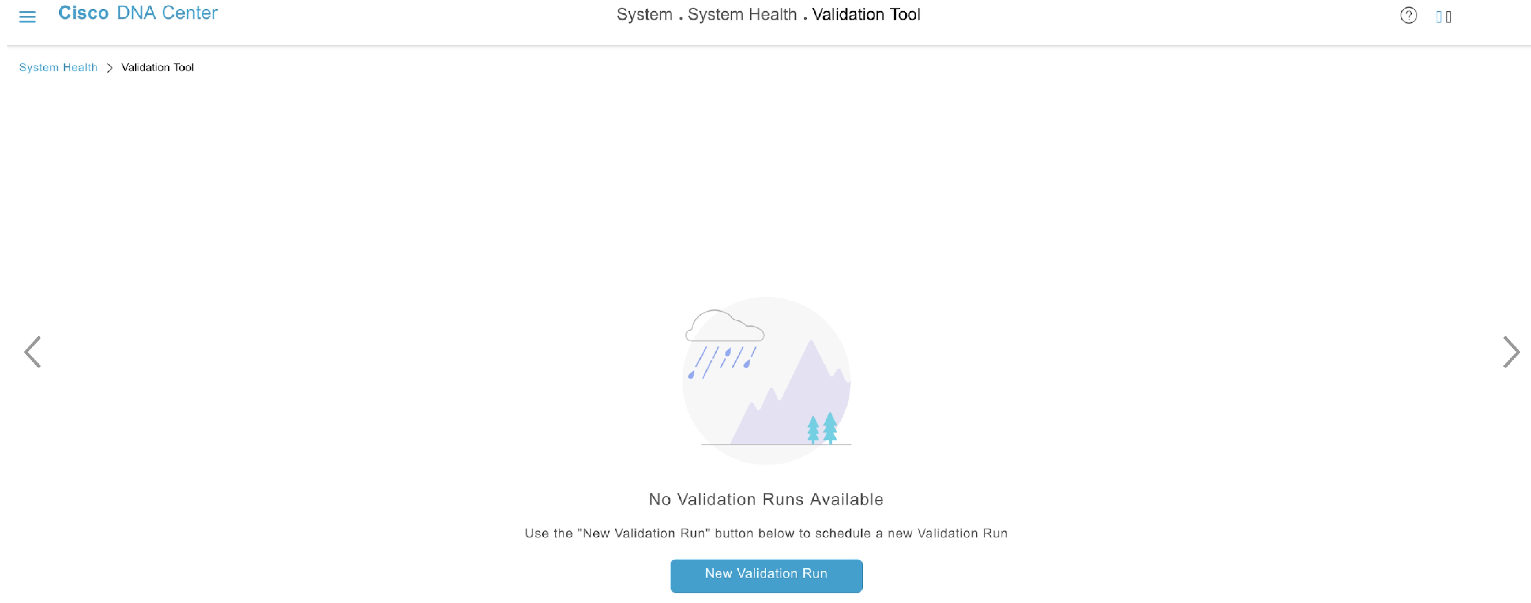
The contents of the Validation Tool page depend on whether Cisco DNA Center has information for any validation runs that completed previously. If it doesn’t, the page looks like this:

Content of Validation Tool page when there are no validation runs completed previously

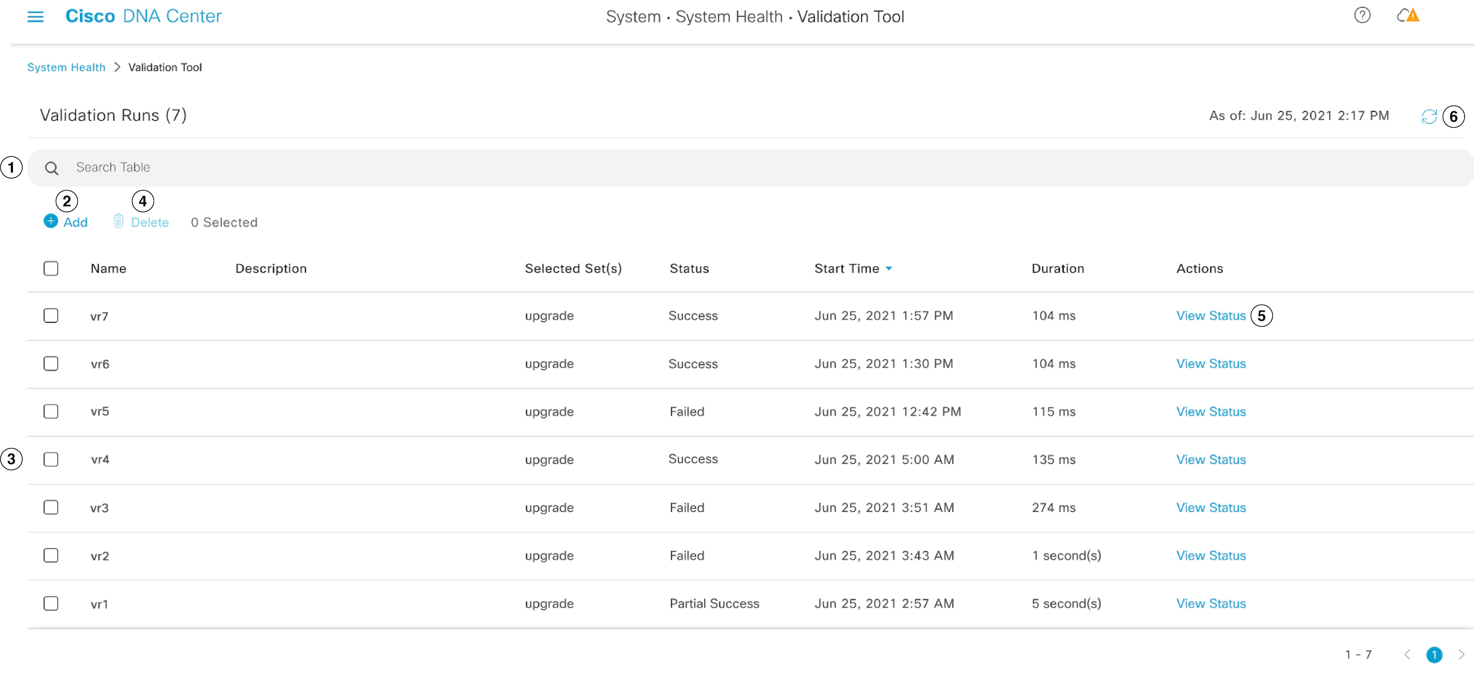
If Cisco DNA Center has validation run information, the page looks like this:

Content of Validation Tool page when the validation run information is available

The following table describes the components that make up the Validation Tool page and their function when validation run information is available.

Callout Description

1

Search Table field: Enter a search string to filter the validation runs that are listed on this page.

2

Add button: Click to open the New Validation Run slide-in pane and enter the required settings for a new run. For more information, see Start a Validation Run.

3

Validation Runs table: Lists the validation runs that completed previously. For each run, the table provides information such as its name, applicable validation set, and completion status. Note the following points:

  • By default, the runs are ordered by start time, with the most recent run listed first.

  • A duration of zero is listed for any run that's currently in progress.

4

Delete button: With the check box for a validation run checked, click to delete the run. Then click Ok in the Warning dialog box to confirm deletion.

Note


You cannot delete a run that is in progress.

5

View Status link: Click to view the details for a particular run. For more information, see View Validation Run Details.

6

Refresh button: Click to refresh the information that is displayed on this page.

Start a Validation Run

To start a validation run, complete the following steps.


Note


Only one validation run can take place at a time. If a validation run is already in progress, you need to wait until it completes before you can initiate another run.


Procedure

Step 1

Do one of the following in the Validation Tool window, depending on whether the Validation Runs table is displayed:

  • If the table is not displayed, it means that either previous validation runs have been deleted or a validation run hasn’t been completed yet. Click New Validation Run.

  • If the Validation Runs table is displayed, click Add.

The New Validation Run slide-in pane opens.

Step 2

In the Name field, enter a name for the validation run.

Ensure that the name that you enter is unique and contains only alphanumeric characters. Special characters aren’t allowed.

Step 3

(Optional) In the Description field, enter a brief description for the validation run you’re about to start.

You can enter a description that contains a maximum of 250 characters.

Step 4

In the Validation Set(s) Selection area, check the check box for the validation sets you want to run.

You can maximize a validation set to view the checks it makes.

Step 5

Click Run.


View Validation Run Details

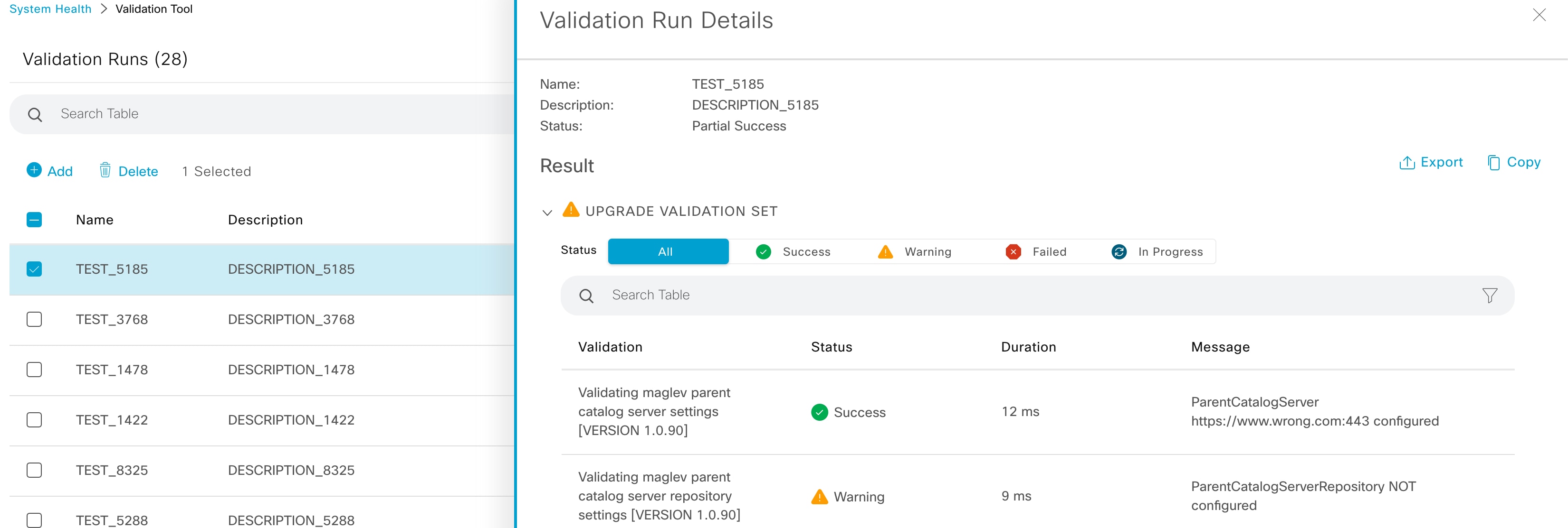
From the Validation Run Details slide-in pane, you can view the checks that were made during the selected run, completion status, duration, and any other relevant information.

Validation Run Details slide-in pane

From here, you can also do the following:

  • To filter the information that’s provided, in the Search Table field, enter a search string.

  • To download the contents of this pane as a .json file, click Export.

  • To copy the contents of this pane, click Copy.

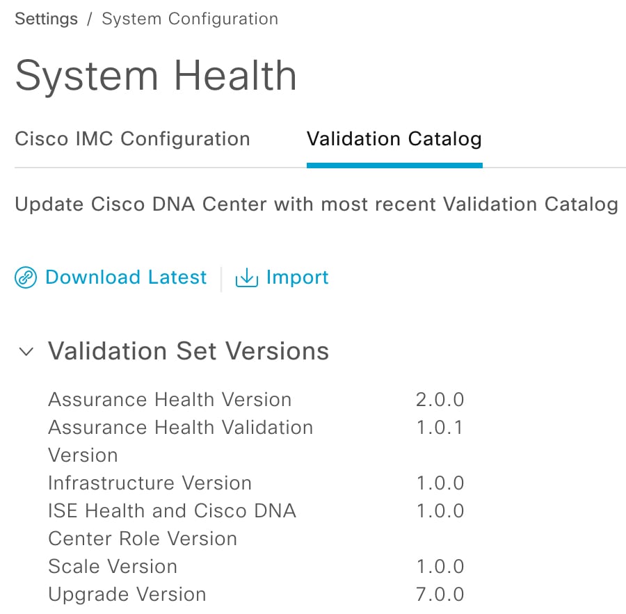
Update the Validation Set

Validation sets should be updated whenever you upgrade Cisco DNA Center. In case you need to update validation sets manually, do the following:

Procedure

Step 1

Click the menu icon () and choose System > Settings > System Configuration > System Health.

System Health validation set settings

Step 2

Click the Validation Catalog tab.

Step 3

Click Download Latest to download a local copy of the latest available validation sets.

Step 4

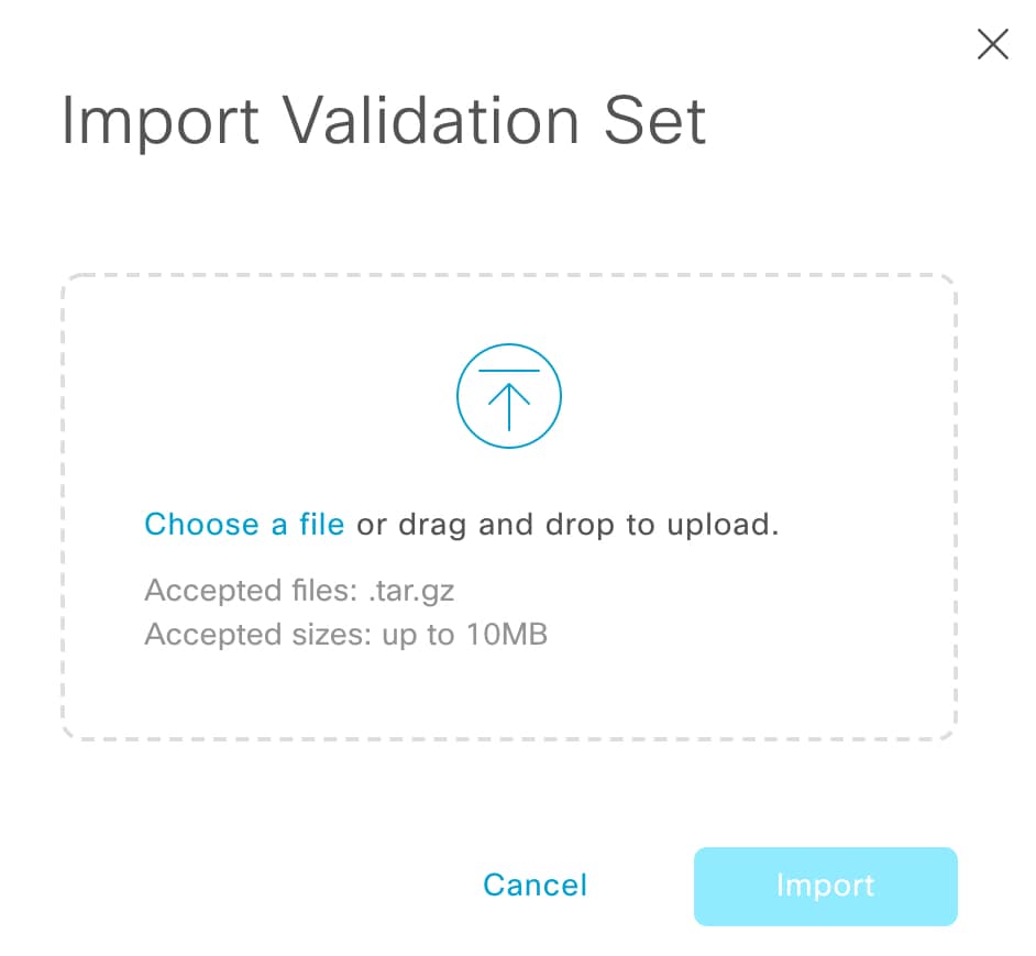
Import the validation set to Cisco DNA Center:

  1. Click Import to open the Import Validation Set dialog box.

    Import Validation Set dialog box
  2. Do one of the following:

    • Click the Choose a file link and navigate to the .tar file that you want to import.

    • Drag and drop the appropriate .tar file from your desktop into the highlighted area.

  3. Click Import.


Use the System Analyzer Tool

If you encounter an issue that requires troubleshooting, you can retrieve log files using the System Analyzer tool. In addition to system-level log files, you can retrieve log files that are specific to Cisco SD-Access and software image management (SWIM). To access the System Analyzer tool, do the following:

  1. Click the menu icon () and choose System > System Health.

    The System Health window opens.

  2. From the Tools drop-down list, choose System Analyzer.

Before you use this tool, note the following points:

  • Only admin users can start system analysis runs, download the resulting log files, and delete completed runs. All users can open and view the System Analysis Details slide-in pane for a selected run.

  • The System Analyzer tool requires 5 GB of disk space on Cisco DNA Center's GlusterFS filesystem.

  • Cisco DNA Center stores either 5 GB or the system analysis runs for the last three months, whichever is smaller.

  • When either of the storage limits are reached, Cisco DNA Center deletes older runs once daily. It also deletes older runs before every new run is started.

  • Since log file information is only useful for troubleshooting, data for system analysis runs is not backed up.

  • In a deployment where HA is enabled, if the System Health service goes down while a run is in progress, you need to restart the run after System Health is up again.

  • In a deployment where disaster recovery is enabled, run data is not replicated across the disaster recovery system's sites. The system's active and standby sites maintain their own run history.

Navigate the System Analyzer Page

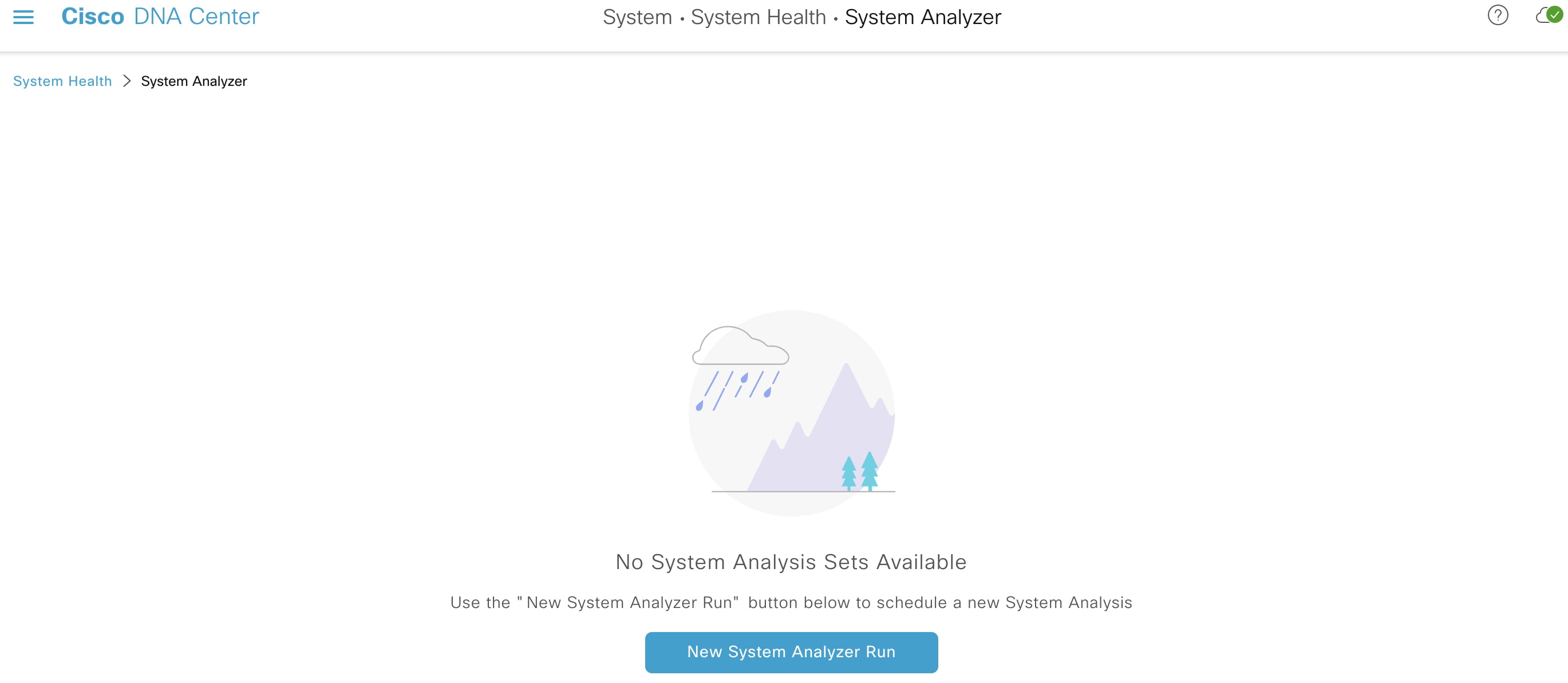
The contents of the System Analyzer page depend on whether Cisco DNA Center has information for any runs that completed previously. If it doesn’t, the page looks like this:

System Analyzer page when there is no information about previously completed runs.

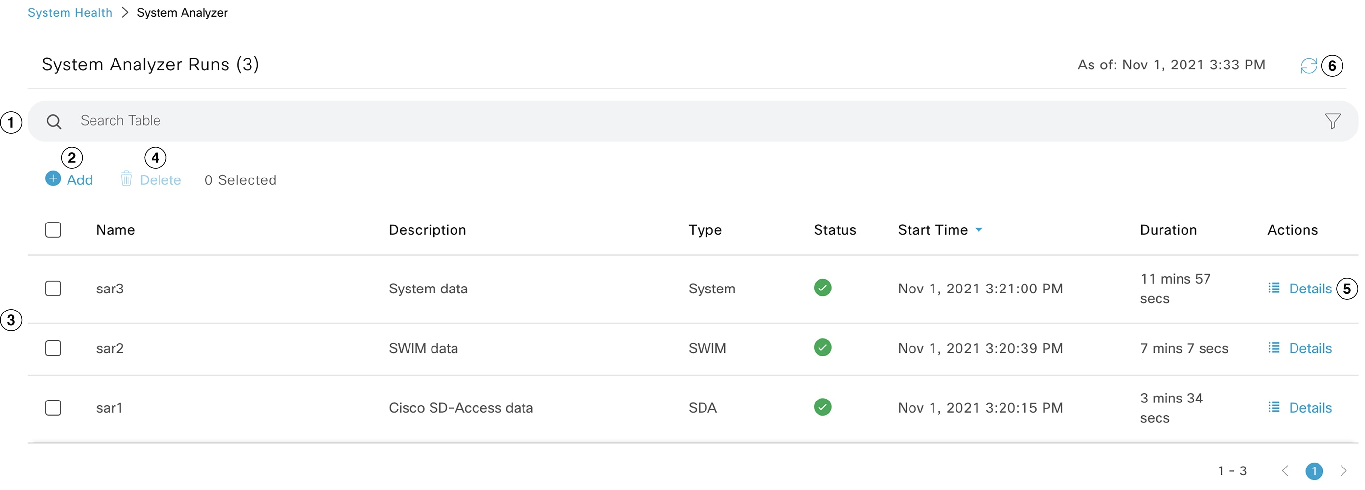
If Cisco DNA Center has run information, the page looks like this:

System Analyzer page when the run information is available.

The following table describes the components that make up the System Analyzer page and their function when run information is available.

Callout Description

1

Search Table field: Enter a search string to filter the runs that are listed on this page.

2

Add button: Click to open the New System Analyzer Run slide-in pane and enter the required settings for a run. See Start a System Analyzer Run for more information.

3

System Analyzer Runs table: Lists the runs that are currently in progress or have completed previously. For each run, the table provides information such as its name, the relevant Cisco DNA Center component, and the amount of time it took to complete the run.

Note the following points:

  • By default, the runs are ordered by start time, with the most recent run listed first.

  • A duration of zero is listed for any run that's currently in-progress.

4

Delete button: With the check box for a run checked, click Delete to remove it.

Note


You cannot delete a run that is in progress.

5

Details link: Click to view the details for a particular run. For more information, see View System Analyzer Run Details.

6

Refresh button: Click to refresh the information that’s displayed on this page.

Start a System Analyzer Run

Complete the following procedure to start a System Analyzer run.

Procedure

Step 1

Do one of the following in the System Analyzer page, depending on whether the System Analyzer Runs table is displayed:

  • If the table is not displayed, it indicates that either previous runs have been deleted or a run hasn’t been completed yet. Click New System Analyzer Run.

  • If the System Analyzer Runs table is displayed, click Add.

The New System Analyzer Run slide-in pane opens.

Step 2

In the Name field, enter a name for the run.

Ensure that the name that you enter is unique and only contains alphanumeric characters. Special characters are not allowed.

Step 3

(Optional) In the Description field, enter a brief description of the run you are about to start.

You can enter a description that contains a maximum of 250 characters.

Step 4

(Optional) In the Notes field, enter any additional information (up to a maximum of 250 characters) you want to provide for the run.

Step 5

In the Select a System Analyzer to run area, click the radio button for the Cisco DNA Center component that you want to retrieve log files for.

Step 6

Click Run.


View System Analyzer Run Details

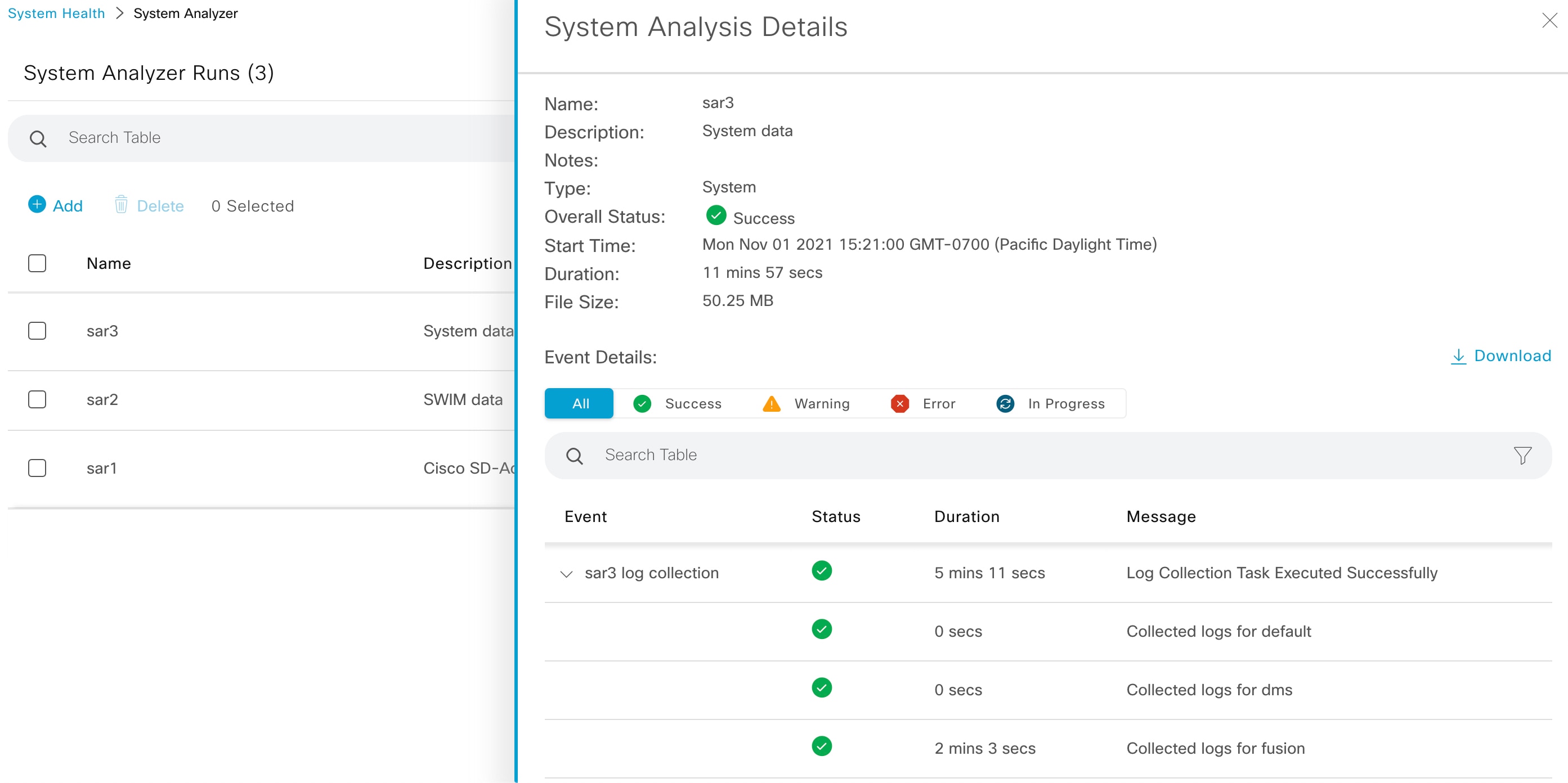
From the System Analysis Details slide-in pane, you can view additional information for the selected run, such as the total file size of the log files that were retrieved and the relevant Cisco DNA Center components. You can also identify any log files that encountered an issue during the run.

System Analysis Details slide-in pane

From here, you can also do the following:

  • In the Search Table field, enter a search string to filter the information that’s displayed.

  • Click Download to download the log files that were retrieved as a .tar.gz file.

To open the System Analysis Details slide-in pane for a particular run, click its Details link in the Actions column.

System Topology Notifications

The following tables list the various notifications that are displayed in the system topology of the System Health page for your Cisco DNA Center appliances and any connected external systems. Notifications are grouped by their corresponding severity:

  • Severity 1 (Error): Indicates a critical error, such as a disabled RAID controller or faulty power supply.

  • Severity 2 (Warning): Indicates an issue such as the inability to establish trust with a Cisco ISE server.

  • Severity 3: (Success): Indicates that a server or hardware component is operating as expected.


    Note


    If all the hardware components on an appliance are operating without any issues, an individual notification is not provided for each component. The following notification is displayed instead: Cisco DNA Center Ok.


Table 1. Cisco DNA Center Appliance Notifications
Component Severity 1 Notification Severity 2 Notification Severity 3 Notification

CPU

Processor CPU1 (SerialNumber - xxxxxx) State is Disabled

Processor CPU1 (SerialNumber - xxxxxx) Health is NotOk and State is Enabled

Processor CPU1 (SerialNumber - xxxxxx) Health is Ok and State is Enabled

Disk

Driver - PD1 State is Disabled

Driver - PD1 Health is Critical and State is Enabled

Driver - PD1 Health is Ok and State is Enabled

MemoryV1

Memory Summary (TOTALSYSTEMMEMORYGIB - 256) Health is NotOk

Memory Summary (TOTALSYSTEMMEMORYGIB - 256) Health is Ok

MemoryV2

Storage DIMM1 (SerialNumber - xxxxx) Status is NotOperable

Storage DIMM1 (SerialNumber - xxxxx) Status is Operable

NIC

NIC Adapter Card MLOM State is Disabled

NIC Adapter Card MLOM State is Enabled and port0 is Down

NIC Adapter Card MLOM State is Enabled and port0 is Up

Power supply

PowerSupply PSU1 (SerialNumber - xxxx) State is Disabled

PowerSupply PSU1 (SerialNumber - xxxx) State is Enabled

RAID

Cisco 12G SAS Modular Raid Controller (SerialNumber - xxxxx) State is Disabled

Cisco 12G SAS Modular Raid Controller (SerialNumber - xxxxx) Health is NotOK and State is Enabled

Cisco 12G SAS Modular Raid Controller (SerialNumber - xxxxx) Health is OK and State is Enabled

Table 2. Connected External System Notifications
Component Severity 1 Notification Severity 2 Notification Severity 3 Notification

Cisco Connected Mobile Experiences (CMX) server

There is a critical issue with the integrated CMX server.

CMX server is integrated and servicing.

IP address management (IPAM) server

There is a critical issue with the connected third-party IPAM provider

  • A third-party IPAM provider is connected.

  • There is no third-party IPAM provider connected.

  • The third-party IPAM provider is currently synchronizing.

Cisco ISE—External RESTful Services (ERS)

ISE PAN ERS connection: ISE ERS API call unauthorized

ISE PAN ERS connection: ERS reachability with ISE - Success

Cisco ISE—Trust

ISE AAA Trust Establishment: Trust Establishment Error

ISE AAA Trust Establishment: Successfully established trust and discovered PSNs from PAN

IT service management (ITSM) server

Servicenow connection health status is NOT up and running

Servicenow connection health status is up and running

Disk Utilization Event Notifications

System Health monitors disk utilization by the nodes in your system and sends a notification whenever utilization on any of these nodes reaches a level that can impact network operations. When utilization exceeds 75%, System Health sends a warning notification. And when utilization exceeds 85%, System Health sends a critical notification. To configure and subscribe to these notifications, complete the steps described in the "Work with Event Notifications" topic of the Cisco DNA Center Platform User Guide. When completing this procedure, ensure that you select and subscribe to the System Performance: Filesystem Utilization event.

Note the following points regarding disk utilization monitoring:

  • After you restore a backup file or upgrade Cisco DNA Center, System Health restarts the monitoring of disk utilization and collects hourly updates.

  • In a three-node HA deployment, every partition that’s configured on the three cluster nodes is monitored. Any notifications that are generated are specific to the relevant partition.

  • In a deployment where disaster recovery is enabled, System Health monitors disk utilization by the nodes at both the active and standby site.

Suggested Actions

The following table lists the issues that you’ll most likely encounter while monitoring the health of your system and suggests actions you can take to remedy those issues.

Component Subcomponent Issue Suggested Actions

Cisco ISE

External RESTful Services (ERS)—Reachability

Timeout elapsed (possibly because the Cisco ISE ERS API load threshold has been exceeded).

  • Check your proxy configuration for a proxy server between Cisco DNA Center and Cisco ISE.

  • Check whether you can reach Cisco ISE from Cisco DNA Center.

Unable to establish a connection with Cisco ISE.

  • Check whether a firewall is configured.

  • Check your proxy configuration for a proxy server between Cisco DNA Center and Cisco ISE.

  • Check whether you can reach Cisco ISE from Cisco DNA Center.

ERS—Availability

No response to ERS API call.

ERS—Authentication

Cisco ISE ERS API call is unauthorized.

Check whether the AAA settings credentials and the Cisco ISE credentials are the same.

ERS—Configuration

Cisco ISE certificate has been changed.

From the Cisco DNA Center GUI, reestablish trust. For more information, see the "Enable PKI in Cisco ISE" topic in the Cisco Identity Services Engine Administrator Guide.

ERS—Unclassified/Generic Error

An undefined diagnostic error occurred.

  1. Delete the AAA settings that are currently configured in Cisco DNA Center.

  2. Reenter the appropriate AAA settings. For more information, see the "Integrate Cisco ISE with Cisco DNA Center" topic in the Cisco Digital Network Architecture Center Second Generation Appliance Installation Guide.

  3. Reestablish trust. For more information, see the "Enable PKI in Cisco ISE" topic in the Cisco Identity Services Engine Administrator Guide.

Trust—Reachability

Unable to establish an HTTPS connection.

Check whether the AAA settings credentials and the Cisco ISE credentials are the same.

The Cisco DNA Center endpoint URL configured for Cisco ISE certificate chain uploads is unreachable.

  • Check your proxy configuration for a proxy server between Cisco DNA Center and Cisco ISE.

  • Check whether you can reach Cisco ISE from Cisco DNA Center.

Trust—Configuration

Invalid Cisco ISE certificate chain.

  • If necessary, regenerate the Cisco ISE internal root CA chain. For more information, see the "ISE CA Chain Regeneration" topic in the Cisco Identity Services Engine Administrator Guide.

  • Ensure that the internal CA certificate chain has not been removed from Cisco ISE.

The Cisco DNA Center endpoint URL configured for Cisco ISE certificate chain uploads is forbidden.

  • Launch the URL and check whether you can access the /aaa/Cisco ISE/certificate directory on the endpoint.

  • Check whether the Use CSRF Check for Enhanced Security option is enabled in Cisco ISE. For more information, see the "Enable External RESTful Services APIs" topic in the Cisco Identity Services Engine Administrator Guide.

Trust—Authentication

The Cisco ISE password has expired.

Trust—Unclassified/Generic Error

An undefined diagnostic error occurred.

  1. Delete the AAA settings that are currently configured in Cisco DNA Center.

  2. Reenter the appropriate AAA settings. For more information, see the "Integrate Cisco ISE with Cisco DNA Center" in the Cisco Digital Network Architecture Center Second Generation Appliance Installation Guide.

  3. Reestablish trust. For more information, see the "Enable PKI in Cisco ISE" topic in the Cisco Identity Services Engine Administrator Guide.

Cisco Connected Mobile Experiences (CMX) server

IP address management (IPAM) server

IT service management (ITSM) server

Reachability

Unable to establish connectivity with the server.

Check whether the server in question is currently down.

Authentication

Unable to log in to the server.

Confirm that the correct login credentials are configured in Cisco DNA Center.

Hardware

Disk

The specified hardware component is experiencing an issue.

Replace the faulty component.

Fan

Power supply

Memory module

CPU

Networking card

RAID controller

Networking

Interfaces are missing.

  1. Connect to Cisco IMC.

  2. If the PID is UCSC-C220-M4, UCSC-C220-M4S, or DN1-HW-APL, complete the following steps:

    1. From the main menu, choose Compute > BIOS > Configure BIOS.

    2. Click the Advanced tab.

    3. Expand LOM and PCIe Slots Configuration.

    4. Enable the disabled mLOMs and reboot the host.

  3. For all other PIDs, replace the faulty component.

System configuration

Hardware configuration

You cannot specify write-back as the write cache policy for the Cisco DNA Center <IP_address> virtual drive. The write policy must be write-through.

  1. Connect to Cisco IMC.

  2. From the main menu, choose Storage > Raid Controller.

  3. Click the Virtual Drive tab.

  4. Select a virtual drive and click Edit. If the write policy is not write-through, update the virtual drives. The write policy must be write-through.

System resources

Storage

The specified mount directory is full.

  • Clear up storage space in the current directory by removing unnecessary data.

  • Specify a new mount directory that has more storage space.

Typical Node Operations

Hardware Peripherals RMA

We recommend that you perform a graceful shutdown of Cisco DNA Center when replacing hardware peripherals such as DIMMs, CPUs, or a single solid-state drive (SSD) during a return materials authorization (RMA) procedure.

Switch Under Maintenance Without HA

If a directly linked switch in the Layer 2 network is undergoing maintenance without a fallback (HA) mechanism to uphold network service, we recommend that you perform a graceful shutdown. To achieve Layer 2 network redundancy, see "NIC Bonding Overview" in the Cisco DNA Center Appliance Installation Guide.

Cisco DNA Center and Cisco ISE Integration

Cisco ISE has three use cases with Cisco DNA Center:

  1. Cisco ISE can be used as a AAA (pronounced "triple A") server for user, device, and client authentication. If you are not using access control policies, or are not using Cisco ISE as a AAA server for device authentication, you do not have to install and configure Cisco ISE.

  2. Access control policies use Cisco ISE to enforce access control. Before you create and use access control policies, integrate Cisco DNA Center and Cisco ISE. The process involves installing and configuring Cisco ISE with specific services, and configuring Cisco ISE settings in Cisco DNA Center. For more information about installing and configuring Cisco ISE with Cisco DNA Center, see the Cisco DNA Center Installation Guide.

  3. If your network uses Cisco ISE for user authentication, configure Assurance for Cisco ISE integration. This integration lets you see more information about wired clients, such as the username and operating system, in Assurance. For more information, see "About Cisco ISE Configuration for Cisco DNA Center" in the Cisco DNA Assurance User Guide.

After Cisco ISE is successfully registered and its trust established with Cisco DNA Center, Cisco DNA Center shares information with Cisco ISE. Cisco DNA Center devices that are assigned to a site that is configured with Cisco ISE as its AAA server have their inventory data propagated to Cisco ISE. Additionally, any updates on these Cisco DNA Center devices (for example, device credentials) in Cisco DNA Center also updates Cisco ISE with the changes.

If a Cisco DNA Center device associated to a site with Cisco ISE as its AAA server is not propagated to Cisco ISE as expected, Cisco DNA Center automatically retries after waiting for a specific time interval. This subsequent attempt occurs when the initial Cisco DNA Center device push to Cisco ISE fails due to any networking issue, Cisco ISE downtime, or any other auto correctable errors. Cisco DNA Center attempts to establish eventual consistency with Cisco ISE by retrying to add the device or update its data to Cisco ISE. However, a retry is not attempted if the failure to propagate the device or device data to Cisco ISE is due to a rejection from Cisco ISE itself, as an input validation error.

If you change the RADIUS shared secret for Cisco ISE, Cisco ISE does not update Cisco DNA Center with the changes. To update the shared secret in Cisco DNA Center to match Cisco ISE, edit the AAA server with the new password. Cisco DNA Center downloads the new certificate from Cisco ISE, and updates Cisco DNA Center.

Cisco ISE does not share existing device information with Cisco DNA Center. The only way for Cisco DNA Center to know about the devices in Cisco ISE is if the devices have the same name in Cisco DNA Center; Cisco DNA Center and Cisco ISE uniquely identify devices for this integration through the device's hostname variable.


Note


The process that propagates Cisco DNA Center inventory devices to Cisco ISE and updates the changes to it are all captured in the Cisco DNA Center audit logs. If there are any issues in the Cisco DNA Center-to-Cisco ISE workflow, view the audit logs in the Cisco DNA Center GUI for information.


Cisco DNA Center integrates with the primary Administration ISE node. When you access Cisco ISE from Cisco DNA Center, you connect with this node.

Cisco DNA Center polls Cisco ISE every 15 minutes. If the Cisco ISE server is down, Cisco DNA Center shows the Cisco ISE server as red (unreachable).

When the Cisco ISE server is unreachable, Cisco DNA Center increases polling to 15 seconds, and then doubles the polling time to 30 seconds, 1 minute, 2 minutes, 4 minutes, and so on, until it reaches the maximum polling time of 15 minutes. Cisco DNA Center continues to poll every 15 minutes for 3 days. If Cisco DNA Center does not regain connectivity, it stops polling and updates the Cisco ISE server status to Untrusted. If this happens, you must reestablish trust between Cisco DNA Center and the Cisco ISE server.

Review the following additional requirements and recommendations to verify Cisco DNA Center and Cisco ISE integration:

  • Cisco DNA Center and Cisco ISE integration is not supported over a proxy server. If you have Cisco ISE configured with a proxy server in your network, configure Cisco DNA Center such that it does not use the proxy server; it can do this by bypassing the proxy server's IP address.

  • Cisco DNA Center and Cisco ISE integration is not supported through a Cisco DNA Center virtual IP address (VIP). If you are using an enterprise CA-issued certificate for Cisco DNA Center, make sure the Cisco DNA Center certificate includes the IP addresses of all interfaces on Cisco DNA Center in the Subject Alternative Name (SAN) extension. If Cisco DNA Center is a three-node cluster, the IP addresses of all interfaces from all three nodes must be included in the SAN extension of the Cisco DNA Center certificate.

  • You must have Admin-level access in Cisco ISE.

  • Disable password expiry for the Admin user in Cisco ISE. Alternatively, make sure that you update the password before it expires. For more information, see the Cisco Identity Services Engine Administrator Guide.

  • When the Cisco ISE certificate changes, Cisco DNA Center must be updated. To do that, edit the AAA server (Cisco ISE), reenter the password, and save. This forces Cisco DNA Center to download the certificate chain for the new admin certificate from Cisco ISE, and update Cisco DNA Center. If you are using Cisco ISE in HA mode, and the admin certificate changes on either the primary or secondary administrative node, you must update Cisco DNA Center.

  • Cisco DNA Center configures certificates for itself and for Cisco ISE to connect over pxGrid. You can use other certificates with pxGrid for connections to other pxGrid clients, such as Firepower. These other connections do not interfere with the Cisco DNA Center and Cisco ISE pxGrid connection.

  • You can change the RADIUS secret password. You provided the secret password when you configured Cisco ISE as a AAA server under System > Settings > External Services > Authentication and Policy Servers. To change the secret password, choose Design > Network Settings > Network and click the Change Shared Secret link. This causes Cisco ISE to use the new secret password when connecting to network devices managed by Cisco DNA Center.

  • In distributed Cisco ISE clusters, each node performs only certain functions, such as PAN (Admin), MnT (Monitoring and Troubleshooting), or PSN (Policy Service). It is possible to have only Admin certificate usage on PAN nodes, and only EAP Authentication certificate usage on PSN nodes. However, this configuration prevents Cisco DNA Center and Cisco ISE integration for pxGrid. Therefore, we recommend that you enable EAP Authentication certificate usage on the Cisco ISE primary PAN node.

  • To ensure that Cisco DNA Center recognizes a PSN after it's been upgraded, you must do the following:

    1. Readd the PAN that's associated with the PSN. In the Cisco Identity Services Engine Administrator Guide, see the "Configure a Primary Policy Administration Node" topic.

    2. Reintegrate Cisco ISE with Cisco DNA Center. In the Cisco DNA Center Installation Guide, see the "Integrate Cisco ISE with Catalyst Center" topic.

  • Cisco DNA Center supports certificate revocation checks via CRL Distribution Point (CDP) and Online Certificate Status Protocol (OCSP). During integration, Cisco DNA Center receives the Cisco ISE admin certificate over port 9060 and verifies its validity based on the CDP and OCSP URLs inside that Cisco ISE admin certificate. If both CDP (which contains a list of CRLs) and OCSP are configured, Cisco DNA Center uses OCSP to verify the revocation status of the certificate and falls back to CDP if the OCSP URL is not accessible. If there are multiple CRLs present in CDP, Cisco DNA Center contacts the next CRL if the first CRL is not reachable. However, due to a JDK PKI Oracle bug, the system does not check for all CRL entries.

    Proxy is not supported for certificate verification. Cisco DNA Center contacts the CRL and OCSP servers without proxy.

    • OCSP and CRL entries are optional in the certificate.

    • LDAP is not supported as a protocol for certificate validation. Do not include LDAP URLs in CDP or AIA extensions.

    • All URLs in CDP and OCSP must be reachable from Cisco DNA Center. Unreachable URLs can cause a poor integration experience, including a failed integration.

  • The Cisco ISE certificates' subject name and issuer must adhere to ASN.1 PrintableString characters, where only spaces and the following characters are allowed: A – Z, a – z, 0 – 9, ‘ ( ) + , - . / : = ?

Anonymize Data

Cisco DNA Center allows you to anonymize wired and wireless endpoints data. You can scramble personally identifiable data, such as the user ID, and device hostname of wired and wireless endpoints.

Ensure that you enable anonymization before you run Discovery. If you anonymize the data after you run Discovery, the new data coming into the system is anonymized, but the existing data isn’t anonymized.

Procedure


Step 1

Click the menu icon () and choose System > Settings > Trust & Privacy > Anonymize Data.

Step 2

In the Anonymize Data window, check the Enable Anonymization check box.

Step 3

Click Save.

After you enable anonymization, you can only search for the device using nonanonymized information such as the MAC address, IP address, and so on.

Configure Authentication and Policy Servers

Cisco DNA Center uses AAA servers for user authentication and Cisco ISE for both user authentication and access control. Use this procedure to configure AAA servers, including Cisco ISE.

Before you begin

  • If you are using Cisco ISE to perform both policy and AAA functions, make sure that Cisco DNA Center and Cisco ISE are integrated.

  • If you are using another product (not Cisco ISE) to perform AAA functions, make sure to do the following:

    • Register Cisco DNA Center with the AAA server, including defining the shared secret on both the AAA server and Cisco DNA Center.

    • Define an attribute name for Cisco DNA Center on the AAA server.

    • For a Cisco DNA Center multihost cluster configuration, define all individual host IP addresses and the virtual IP address for the multihost cluster on the AAA server.

  • Before you configure Cisco ISE, confirm that:

    • You have deployed Cisco ISE on your network. For information on supported Cisco ISE versions, see the Cisco DNA Center Compatibility Matrix. For information on installing Cisco ISE, see the Cisco Identity Services Engine Install and Upgrade guides.

    • If you have a standalone ISE deployment, you must integrate Cisco DNA Center with the Cisco ISE node and enable the pxGrid service and External RESTful Services (ERS) on that node.


      Note


      Although pxGrid 2.0 allows up to four pxGrid nodes in the Cisco ISE deployment, Cisco DNA Center releases earlier than 2.2.1.x do not support more than two pxGrid nodes.


    • If you have a distributed Cisco ISE deployment:

      • You must integrate Cisco DNA Center with the primary policy administration node (PAN), and enable ERS on the PAN.


        Note


        We recommend that you use ERS through the PAN. However, for backup, you can enable ERS on the PSNs.


      • You must enable the pxGrid service on one of the Cisco ISE nodes within the distributed deployment. Although you can choose to do so, you do not have to enable pxGrid on the PAN. You can enable pxGrid on any Cisco ISE node in your distributed deployment.

      • The PSNs that you configure in Cisco ISE to handle TrustSec or SD Access content and PACs must also be defined in Work Centers > Trustsec > Trustsec Servers > Trustsec AAA Servers. For more information, see the Cisco Identity Services Engine Administrator Guide.

    • You must enable communication between Cisco DNA Center and Cisco ISE on the following ports: 443, 5222, 8910, and 9060.

    • The Cisco ISE host on which pxGrid is enabled must be reachable from Cisco DNA Center on the IP address of the Cisco ISE eth0 interface.

    • The Cisco ISE node can reach the fabric underlay network via the appliance's NIC.

    • The Cisco ISE admin node certificate must contain the Cisco ISE IP address or FQDN in either the certificate subject name or the Subject Alternative Name (SAN).

    • The Cisco DNA Center system certificate must list both the Cisco DNA Center appliance IP address and FQDN in the SAN field.


      Note


      For Cisco ISE 2.4 Patch 13, 2.6 Patch 7, and 2.7 Patch 3, if you are using the Cisco ISE default self-signed certificate as the pxGrid certificate, Cisco ISE might reject that certificate after applying those patches. This is because the older versions of that certificate have the Netscape Cert Type extension specified as the SSL server, which now fails (because a client certificate is required).

      This issue doesn’t occur in Cisco ISE 3.0 and later. For more information, see the Cisco ISE Release Notes.


Procedure


Step 1

Click the menu icon () and choose System > Settings > External Services > Authentication and Policy Servers.

Step 2

From the Add drop-down list, choose AAA or ISE.

Step 3

To configure the primary AAA server, enter the following information:

  • Server IP Address: IP address of the AAA server.

  • Shared Secret: Key for device authentications. The shared secret can contain up to 100 characters.

Note


Make sure that you do not configure a PSN that is part of an existing Cisco ISE cluster as a primary AAA server.

Step 4

To configure a Cisco ISE server, enter the following details:

  • Server IP Address: IP address of the Cisco ISE server.

  • Shared Secret: Key for device authentications.

  • Username: Username that is used to log in to Cisco ISE via HTTPS.

  • Password: Password for the Cisco ISE HTTPS username.

    Note


    The username and password must be an ISE admin account that belongs to the Super Admin.

  • FQDN: Fully qualified domain name (FQDN) of the Cisco ISE server.

    Note

     
    • We recommend that you copy the FQDN that is defined in Cisco ISE (Administration > Deployment > Deployment Nodes > List) and paste it directly into this field.

    • The FQDN that you enter must match the FQDN, Common Name (CN), or Subject Alternative Name (SAN) defined in the Cisco ISE certificate.

    The FQDN consists of two parts, a hostname and the domain name, in the following format:

    hostname.domainname.com

    For example, the FQDN for a Cisco ISE server can be ise.cisco.com.

  • Virtual IP Address(es): Virtual IP address of the load balancer behind which the Cisco ISE policy service nodes (PSNs) are located. If you have multiple PSN farms behind different load balancers, you can enter a maximum of six virtual IP addresses.

Step 5

Click Advanced Settings and configure the settings:

  • Connect to pxGrid: Check this check box to enable a pxGrid connection.

    If you want to use the Cisco DNA Center system certificate as the pxGrid client certificate (sent to Cisco ISE to authenticate the Cisco DNA Center system as a pxGrid client), check the Use Cisco DNA Center Certificate for pxGrid check box. You can use this option if all the certificates that are used in your operating environments must be generated by the same CA. If this option is disabled, Cisco DNA Center will send a request to Cisco ISE to generate a pxGrid client certificate for the system to use.

    When you enable this option, ensure that:

    • The Cisco DNA Center certificate is generated by the same Certificate Authority (CA) as is in use by Cisco ISE (otherwise, the pxGrid authentication fails).

    • The Certificate Extended Key Use (EKU) field includes "Client Authentication."

  • Protocol: TACACS and RADIUS (the default). You can select both protocols.

    Attention


    If you do not enable TACAS for a Cisco ISE server here, you cannot configure the Cisco ISE server as a TACACS server under Design > Network Settings > Network when configuring a AAA server for network device authentication.

  • Authentication Port: Port used to relay authentication messages to the AAA server. The default UDP port is 1812.

  • Accounting Port: Port used to relay important events to the AAA server. The default UDP port is 1813.

  • Port: The default TACACS port is 49.

  • Retries: Number of times that Cisco DNA Center attempts to connect with the AAA server before abandoning the attempt to connect. The default number of attempts is 3.

  • Timeout: The time period for which the device waits for the AAA server to respond before abandoning the attempt to connect. The default timeout is 4 seconds.

Note


After the required information is provided, Cisco ISE is integrated with Cisco DNA Center in two phases. It takes several minutes for the integration to complete. The phase-wise integration status is shown in the Authentication and Policy Servers window and System 360 window:

Cisco ISE server registration phase:

  • Authentication and Policy Servers window: "In Progress"

  • System 360 window: "Primary Available"

pxGrid subscriptions registration phase:

  • Authentication and Policy Servers window: "Active"

  • System 360 window: "Primary Available" and "pxGrid Available"

If the status of the configured Cisco ISE server is shown as "FAILED" due to a password change, click Retry, and update the password to resynchronize the Cisco ISE connectivity.

Step 6

Click Add.

Step 7

To add a secondary server, repeat the preceding steps.


Configure Cisco AI Network Analytics

Use this procedure to enable the Cisco AI Analytics features to export network event data from network devices and inventory, site hierarchy, and topology data to the Cisco AI Cloud.

Before you begin

  • Make sure that you have the Cisco DNA Advantage software license for Cisco DNA Center. The AI Network Analytics application is part of the Cisco DNA Advantage software license.

  • Make sure that the latest version of the AI Network Analytics application is installed. See Download and Install Application Updates.

  • Make sure that your network or HTTP proxy is configured to allow outbound HTTPS (TCP 443) access to the following cloud hosts:

    • api.use1.prd.kairos.ciscolabs.com (US East Region)

    • api.euc1.prd.kairos.ciscolabs.com (EU Central Region)

Procedure


Step 1

Click the menu icon () and choose System > Settings.

Step 2

Scroll down to External Services and choose Cisco AI Analytics.

The AI Network Analytics window opens.
AI Network Analytics window in the Cisco DNA Center GUI

Step 3

Do one of the following:

  • If you have an earlier version of Cisco AI Network Analytics installed in your appliance, do the following:
    1. Click Recover from a config file.

      The Restore AI Network Analytics window opens.

    2. Drag-and-drop the configuration files in the area provided or choose the files from your file system.

    3. Click Restore.

      Cisco AI Network Analytics might take a few minutes to restore, and then the Success dialog box opens.

  • For the first-time configuration of Cisco AI Network Analytics, do the following:
    1. Click Configure.

    2. In the Where should we securely store your data? area, choose the location to store your data. Options are: Europe (Germany) or US East (North Virginia).

      The system starts testing cloud connectivity as indicated by the Testing cloud connectivity... tab. After cloud connectivity testing completes, the Testing cloud connectivity... tab changes to Cloud connection verified.

    3. Click Next.

      The terms and conditions window opens.

    4. Click the Accept Cisco Universal Cloud Agreement check box to agree to the terms and conditions, and then click Enable.

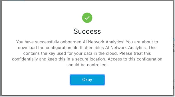
      Cisco AI Network Analytics might take a few minutes to enable, and then the Success dialog box opens.
      Success dialog box after the successful configuration of Cisco AI Network Analytics

Step 4

In the Success dialog box, click Okay.

The AI Network Analytics window opens, and the Enable AI Network Analytics toggle button displays Enable AI Network Analytics toggle button in the AI Network Analytics window.

Step 5

(Recommended) In the AI Network Analytics window, click Download Configuration file.


Client Certificate Renewal

AI agents use X.509 client certificates to authenticate to the AI Cloud. Certificates are created and signed by the AI Cloud CA upon tenant onboarding to the AI Cloud and remain valid for three years (reduced to one year in August 2021). Before their expiration, client certificates must be renewed to avoid losing cloud connectivity. An automatic certificate renewal mechanism is in place. This mechanism requires that you manually back up the certificate after renewal. The backup is required in case you restore or migrate to a new Cisco DNA Center.

After renewal, a notification is shown on every AI Analytics window (Peer Comparison, Heatmap, Network Comparison, Trends and Insights) to tell you to back up the new AI Network Analytics configuration.

Disable Cisco AI Network Analytics

To disable Cisco AI Network Analytics data collection, you must disable the AI Network Analytics feature, as follows:

Procedure


Step 1

Click the menu icon () and choose System > Settings.

Step 2

Scroll down to External Services and choose Cisco AI Analytics.

For each feature, a check mark ( Check mark icon indicating that the feature is enabled in the Cisco AI Analytics window ) indicates that the feature is enabled. If the check box is unchecked ( Unchecked check box indicating that the feature is disabled in the Cisco AI Analytics window ), the feature is disabled.

Step 3

In the AI Network Analytics area, click the Enable AI Network Analytics toggle button so that it’s unchecked ( Enable AI Network Analytics toggle button that is uncheked ).

Step 4

Click Update.

Step 5

To delete your network data from the Cisco AI Network Analytics cloud, contact the Cisco Technical Response Center (TAC) and open a support request.

Step 6

If you have misplaced your previous configuration, click Download configuration file.


Update the Machine Reasoning Knowledge Base

Machine Reasoning knowledge packs are step-by-step workflows that are used by the Machine Reasoning Engine (MRE) to identify security issues and improve automated root cause analysis. These knowledge packs are continuously updated as more information is received. The Machine Reasoning Knowledge Base is a repository of these knowledge packs (workflows). To have access to the latest knowledge packs, you can either configure Cisco DNA Center to automatically update the Machine Reasoning Knowledge Base daily, or you can perform a manual update.

Procedure


Step 1

Click the menu icon () and choose System > Settings.

Step 2

Scroll down to External Services and choose Machine Reasoning Knowledge Base.

The Machine Reasoning Knowledge Base window shows the following information:
  • INSTALLED: Shows the installed version and installation date of the Machine Reasoning Knowledge Base package.

When there’s a new update to the Machine Reasoning Knowledge Base, the AVAILABLE UPDATE area is displayed in the Machine Reasoning Knowledge Base window, which provides the Version and Details about the update.

  • AUTO UPDATE: Automatically updates the Machine Reasoning Knowledge Base in Cisco DNA Center daily.

  • CISCO CX CLOUD SERVICE FOR NETWORK BUG IDENTIFIER AND SECURITY ADVISORY: Integrates Cisco DNA Center with CX Cloud that allows you to perform an automated config. This integration provides enhanced vulnerability detection on devices directly from the security advisories tool on Cisco DNA Center.

Step 3

(Recommended) Check the AUTO UPDATE check box to automatically update the Machine Reasoning Knowledge Base.

The Next Attempt area shows the date and time of the next update.

You can perform an automatic update only if Cisco DNA Center is successfully connected to the Machine Reasoning Engine in the cloud.

Step 4

To manually update the Machine Reasoning Knowledge Base in Cisco DNA Center, do one of the following:

  • Under AVAILABLE UPDATES, click Update. A Success pop-up window appears with the status of the update.
  • Manually download the Machine Reason Knowledge Base to your local machine and import it to Cisco DNA Center. Do the following:
    1. Click Download.

      The Opening mre_workflow_signed dialog box appears.

    2. Open or save the downloaded file to the desired location in your local machine, and then click OK.

    3. Click Import to import the downloaded Machine Reasoning Knowledge Base from your local machine to Cisco DNA Center.

Step 5

Check the CISCO CX CLOUD SERVICE FOR NETWORK BUG IDENTIFIER AND SECURITY ADVISORY check box to enable Cisco CX Cloud connection with network bug identifier and security advisory.

Step 6

In the Security Advisories Settings area click the RECURRING SCAN toggle button to enable or disable the weekly recurring scan.

Step 7

Click the CISCO CX CLOUD toggle button to enable or disable the Cisco CX cloud.


Cisco Accounts

Configure Cisco Credentials

You can configure Cisco credentials for Cisco DNA Center. Cisco credentials are the username and password that you use to log in to the Cisco website to access software and services.


Note


The Cisco credentials configured for Cisco DNA Center using this procedure are used for software image and update downloads. The Cisco credentials are also encrypted by this process for security purposes.


Before you begin

Only a user with SUPER-ADMIN-ROLE permissions can perform this procedure. For more information, see About User Roles.

Procedure


Step 1

Click the menu icon () and choose System > Settings > Cisco Accounts > Cisco.com Credentials.

Step 2

Enter your Cisco username and password.

Step 3

Click Save.

Your cisco.com credentials are configured for the software and services.


Clear Cisco Credentials

To delete the cisco.com credentials that are currently configured for Cisco DNA Center, complete the following procedure.


Note


  • When you perform any tasks that involve software downloads or device provisioning and cisco.com credentials are not configured, you’ll be prompted to enter them before you can proceed. In the resulting dialog box, check the Save For Later check box in order to save these credentials for use throughout Cisco DNA Center. Otherwise, you’ll need to enter credentials each time you perform these tasks.

  • Completing this procedure will undo your acceptance of the end-user license agreement (EULA). See Accept the License Agreement for a description of how to reenter EULA acceptance.


Before you begin

Only a user with SUPER-ADMIN-ROLE permissions can perform this procedure. For more information, see About User Roles.

Procedure


Step 1

Click the menu icon () and choose System > Settings > Cisco Accounts > Cisco.com Credentials.

Step 2

Click Clear.

Step 3

In the resulting dialog box, click Continue to confirm the operation.


Configure Connection Mode

Connection mode manages the connections between smart-enabled devices in your network that interact with Cisco DNA Center and the Cisco Smart Software Manager (SSM). Ensure that you have SUPER-ADMIN access permission to configure the different connection modes.

Procedure


Step 1

Click the menu icon () and choose System > Settings > Cisco Accounts > SSM Connection Mode.

The following connection modes are available:

  • Direct

  • On-Prem CSSM

  • Smart proxy

Step 2

Choose Direct to enable a direct connection to the Cisco SSM cloud.

Step 3

If your organization is security sensitive, choose On-Prem CSSM. The on-prem option lets you access a subset of Cisco SSM functionality without using a direct internet connection to manage your licenses with the Cisco SSM cloud.

  1. Before you enable On-Prem CSSM, confirm that the satellite is deployed, up, and running in your network site.

    If the satellite is configured with FQDN, the call-home configuration of satellite FQDN is pushed instead of the IP address.

  2. Enter the details for the On-Prem CSSM Host, Smart Account Name, Client ID, and Client Secret.

    Do not use a space or an underscore in the Smart Account name.

    For information about how to retrieve the client ID and client secret, see the Cisco Smart Software Manager On-Prem User Guide.
  3. Click Test Connection to validate the Cisco SSM connection.

  4. Click Save and then Confirm.

  5. If there are devices that need to be registered again with the changed SSM, the Need to Re-Register Devices dialog box appears. Click OK in the dialog box.

  6. In the Tools > License Manager > Devices window, choose the devices that you want to register again and click Finish Connection Mode Changes.

  7. In the Resync Devices dialog box, do the following:

    • Enter the Smart Account.

    • Enter the Virtual Account.

    • Click Now to start the resync immediately or click Later to schedule the resync at a specific time.

    • Click Resync.

    The Recent Tasks window shows the resync status of the devices.

Step 4

Choose Smart proxy to register your smart-enabled devices with the Cisco SSM cloud through Cisco DNA Center. With this mode, devices do not need a direct connection to the Cisco SSM cloud. Cisco DNA Center proxies the requests from the device to the Cisco SSM cloud through itself.

While provisioning the call-home configuration to the device, if the satellite is configured with FQDN, the FQDN of the satellite is pushed instead of the IP address.


Register Plug and Play

You can register Cisco DNA Center as a controller for Cisco Plug and Play (PnP) Connect, in a Cisco Smart Account for redirection services. This lets you synchronize the device inventory from the Cisco PnP Connect cloud portal to PnP in Cisco DNA Center.

Before you begin

Only a user with SUPER-ADMIN-ROLE or CUSTOM-ROLE with system management permissions can perform this procedure.

In the Smart account, users are assigned roles that specify the functions and authorized to perform:

  • Smart Account Admin user can access all the Virtual Accounts.

  • Users can access assigned Virtual Accounts only.

Procedure


Step 1

Click the menu icon () and choose System > Settings > Cisco Accounts > PnP Connect.

A table of PnP connected profiles is displayed.

Step 2

Click Register to register a virtual account.

Step 3

In the Register Virtual Account window, the Smart Account you configured is displayed in the Select Smart Account drop-down list. You can select an account from the Select Virtual Account drop-down list.

Step 4

Click the required IP or FQDN radio button.

Step 5

Enter the IP address or FQDN (Fully Qualified Domain Name) of the controller.

Step 6

Enter the profile name. A profile is created for the selected virtual account with the configuration that you provided.

Step 7

Check the Use as Default Controller Profile check box to register this Cisco DNA Center controller as the default controller in the Cisco PnP Connect cloud portal.

Step 8

Click Register.


Create PnP Event Notifications

You receive a notification whenever a Plug and Play (PnP) event takes place in Cisco DNA Center by creating event notifications. See the "Work with Event Notifications" topic in the Cisco DNA Center Platform User Guide to configure the supported channels and create event notifications.

Ensure that you create event notifications to the following PnP events:

Event Name

Event ID

Description

Add device failed

NETWORK-TASK_FAILURE-3-008

Device(s) are not added through single or bulk import. An error occurs when adding devices through single or bulk import.

Add device successful

NETWORK-TASK_COMPLETE-4-007

Device(s) are added through single or bulk import successfully.

Device in error state

NETWORK-ERROR_1-002

Device goes to Error state.

Device in provisioned state

NETWORK-INFO_4-003

Device goes to Provisioned state.

Device stuck in onboarding state

NETWORK-TASK_PROGRESS-2-006

Device is stuck in onboarding state for more than 15 minutes.

Device waiting to be claimed

NETWORK-INFO_2-001

Device reaches Unclaimed state and is ready to be provisioned.

Smart Account sync failed

NETWORK-TASK_FAILURE-1-005

Smart Account sync is failed for some devices.

Smart Account sync successful

NETWORK-TASK_COMPLETE-4-004

Smart Account sync is successful for some devices.

Configure Smart Account

Cisco Smart Account credentials are used for connecting to your Smart Licensing account. The License Manager tool uses the details of license information from this Smart Account for entitlement and license management.

Before you begin

Ensure that you have SUPER-ADMIN-ROLE permissions.

Procedure


Step 1

Click the menu icon () and choose System > Settings > Cisco Accounts > Smart Account.

Step 2

Click the Add button. You are prompted to provide Smart Account credentials.

  1. Enter your Smart Account username and password.

  2. Click Save.

    Your Smart Account is configured.

Step 3

If you want to change the selected Smart Account Name, click Change. You will be prompted to select the Smart Account that will be used for connecting to your Smart Licensing Account on Cisco SSM cloud.

  1. Choose the Smart Account from the drop-down list.

  2. Click Save.

Step 4

Click View all virtual accounts to view all the virtual accounts associated with the Smart Account.

Note


Cisco Accounts supports multiple smart and virtual accounts.

Step 5

(Optional) If you want to register smart license-enabled devices automatically to a virtual account, check the Auto register smart license enabled devices check box. A list of virtual accounts associated with the smart account is displayed.

Step 6

Select the required virtual account. Whenever a smart license-enabled device is added in the inventory, it’s automatically registered to the selected virtual account.

Step 7

If you want to remove the licensed smart account users and their associated historical data, click Delete historical information.

The Delete Historical Data slide-in pane displays the licensed smart account users. It also displays the existing smart accounts that aren’t currently present in Cisco DNA Center, but their historical data is still available.

Step 8

In the Smart Account list area check the check box next to the smart account that you want to delete.

Step 9

Click Delete.

Step 10

Click Delete in the subsequent confirmation window.

Step 11

Check the Delete the associated license historical information check box to delete the historical information of the associated license.


Smart Licensing

Cisco Smart Licensing is a flexible licensing model that provides you with an easier, faster, and more consistent way to purchase and manage software across the Cisco portfolio and across your organization. And it's secure—you control what users can access. With Smart Licensing, you get:

  • Easy Activation: Smart Licensing establishes a pool of software licenses that can be used across the entire organization—no more product activation keys (PAKs).

  • Unified Management: My Cisco Entitlements (MCE) provides a complete view into all of your Cisco products and services in an easy-to-use portal, so you always know what you have and what you are using.

  • License Flexibility: Your software is not node-locked to your hardware, so you can easily use and transfer licenses as needed.

To use Smart Licensing, you must first set up a Smart Account on Cisco Software Central (software.cisco.com).

For a more detailed overview on Cisco licensing, go to cisco.com/go/licensingguide.

Before you begin

  • To enable Smart Licensing, you must configure Cisco Credentials (see Configure Cisco Credentials) and upload Cisco DNA Center license conventions in Cisco SSM.

  • Smart Licensing is not supported when the System > Settings > Cisco Accounts > SSM Connection Mode is On-Prem CSSM.

Procedure


Step 1

Click the menu icon () and choose System > Settings > Cisco Accounts > Smart Licensing.

By default, Smart User and Smart Domain details are displayed.

Step 2

Choose a virtual account from the Search Virtual Account drop-down list to register.

Step 3

Click Register.

Step 4

After successful registration, click the View Available Licenses link to view the available Cisco DNA Center licenses.


Device Controllability

Device controllability is a system-level process on Cisco DNA Center that enforces state synchronization for some device-layer features. Its purpose is to aid in the deployment of network settings that Cisco DNA Center needs to manage devices. Changes are made on network devices when running discovery, when adding a device to inventory, or when assigning a device to a site.

To view the configuration that is pushed to the device, go to Provision > Inventory and from the Focus drop-down list, choose Provision. In the Provision Status column, click See Details.


Note


When Cisco DNA Center configures or updates devices, the transactions are captured in the audit logs, which you can use to track changes and troubleshoot issues.


The following device settings are enabled as part of device controllability:

  • Device Discovery

    • SNMP Credentials

    • NETCONF Credentials

  • Adding Devices to Inventory

    Cisco TrustSec (CTS) Credentials


    Note


    Cisco TrustSec (CTS) Credentials are pushed during inventory only if the Global site is configured with Cisco ISE as AAA. Otherwise, CTS is pushed to devices during "Assign to Site" when the site is configured with Cisco ISE as AAA.


  • Assigning Devices to a Site

    • Controller Certificates

    • SNMP Trap Server Definitions

    • Syslog Server Definitions

    • NetFlow Server Definitions

    • Wireless Service Assurance (WSA)

    • IPDT Enablement

Device controllability is enabled by default. If you do not want device controllability enabled, disable it manually. For more information, see Configure Device Controllability.

When device controllability is disabled, Cisco DNA Center does not configure any of the preceding credentials or features on devices while running discovery or when the devices are assigned to a site.

The following circumstances dictate whether or not device controllability configures network settings on devices:

  • Device Discovery: If SNMP and NETCONF credentials are not already present on a device, these settings are configured during the discovery process.

  • Device in Inventory: After a successful initial inventory collection, IPDT is configured on the devices.

    In earlier releases, the following IPDT commands were configured:

    ip device tracking
    ip device tracking probe delay 60
    ip device tracking probe use-svi

    For each interface:

    interface $physicalInterface
    ip device tracking maximum 65535

    In the current release, the following IPDT commands are configured for any newly discovered device:

    device-tracking tracking
    device-tracking policy IPDT_POLICY
    tracking enable

    For each interface:

    interface $physicalInterface
    device-tracking attach-policy IPDT_POLICY
  • Device in Global Site: When you successfully add, import, or discover a device, Cisco DNA Center places the device in the Managed state and assigns it to the Global site by default. Even if you have defined SNMP server, Syslog server, and NetFlow collector settings for the Global site, Cisco DNA Center does not change these settings on the device.

  • Device Moved to Site: If you move a device from the Global site to a new site that has SNMP server, Syslog server, and NetFlow collector settings configured, Cisco DNA Center changes these settings on the device to the settings configured for the new site.

  • Device Removed from Site: If you remove a device from a site, Cisco DNA Center does not remove the SNMP server, Syslog server, and NetFlow collector settings from the device.

  • Device Deleted from Cisco DNA Center: If you delete a device from Cisco DNA Center and check the Configuration Clean-up check box, the SNMP server, Syslog server, and NetFlow collector settings are removed from the device.

  • Device Moved from Site to Site: If you move a device—for example, from Site A to Site B—Cisco DNA Center replaces the SNMP server, Syslog server, and NetFlow collector settings on the device with the settings assigned to Site B.

  • Update Site Telemetry Changes: The changes made to any settings that are under the scope of device controllability are applied to the network devices during device provisioning or when the Update Telemetry Settings action is performed.

When device controllability is enabled, if Cisco DNA Center can't connect to the device through the user-provided SNMP credentials and collect device information, Cisco DNA Center pushes the user-provided SNMP credentials to the device. For SNMPv3, the user is created under the default group.


Note


For Cisco AireOS devices, the user-provided SNMPv3 passphrase must contain from 12 to 31 characters.


Configure Device Controllability

Device controllability aids deployment of the required network settings that Cisco DNA Center needs to manage devices.


Note


If you disable device controllability, none of the credentials or features described in the Device Controllability page will be configured on the devices during discovery or at runtime.

Device controllability is enabled by default. To manually disable device controllability, do the following:

Procedure


Step 1

Click the menu icon () and choose System > Settings > Device Settings > Device Controllability.

Step 2

Uncheck the Enable Device Controllability check box.

Step 3

Click Save.


Accept the License Agreement

You must accept the end-user license agreement (EULA) before downloading software or provisioning a device.


Note


If you have not yet configured cisco.com credentials, you are prompted to configure them in the Device EULA Acceptance window before proceeding.


Procedure


Step 1

Click the menu icon () and choose System > Settings > Device Settings > Device EULA Acceptance.

Step 2

Click the Cisco End User License Agreement link and read the EULA.

Step 3

Check the I have read and accept the Device EULA check box.

Step 4

Click Save.


Configure SNMP Properties

You can configure retry and timeout values for SNMP.

Before you begin

Only a user with SUPER-ADMIN-ROLE permissions can perform this procedure. For more information, see About User Roles.

Procedure


Step 1

Click the menu icon () and choose System > Settings > Device Settings > SNMP.

Step 2

Configure the following fields:

  • Retries: Number of attempts allowed to connect to the device. Valid values are from 1 to 3. The default is 3.

  • Timeout: Number of seconds Cisco DNA Center waits when trying to establish a connection with a device before timing out. Valid values are from 1 to 300 seconds in intervals of 5 seconds. The default is 5 seconds.

Step 3

Click Save.

Step 4

(Optional) To return to the default settings, click Reset and Save.


Enable ICMP Ping

When Internet Control Message Protocol (ICMP) ping is enabled and there are unreachable access points in FlexConnect mode, Cisco DNA Center uses ICMP to ping these access points every 5 minutes to enhance reachability.

The following procedure describes how to enable an ICMP ping.

Procedure


Step 1

Click the menu icon () and choose System > Settings > Device Settings > ICMP Ping.

Step 2

Check the Enable ICMP ping for unreachable access points in FlexConnect mode check box.

Step 3

Click Save.


Configure AP Location for PnP Onboarding

Cisco DNA Center allows you to use the site assigned during the PnP claim as the AP location for PnP onboarding. If you check the Configure AP Location check box, Cisco DNA Center configures the assigned site as the AP location for PnP onboarding. If you uncheck this check box, use the Configure Access Points workflow to configure the AP location for PnP onboarding. For more information, see "AP Configuration in Cisco DNA Center" in the Cisco DNA Center User Guide.


Note


These settings aren’t applicable during the day-n operations. To configure the AP location for day-n operations, you can use the Configure Access Points workflow.


Procedure


Step 1

Click the menu icon () and choose System > Settings > Device Settings > PnP AP Location.

Step 2

Check the Configure AP Location check box.

Step 3

Click Save.


Configure an Image Distribution Server

An image distribution server helps in the storage and distribution of software images. You can configure up to three external image distribution servers to distribute software images. You can also set up one or more protocols for the newly added image distribution servers.

Procedure


Step 1

Click the menu icon () and choose System > Settings > Device Settings > Image Distribution Servers.

Step 2

In the Image Distribution Servers window, click Servers.

The table displays details about the host, username, SFTP, SCP, and connectivity of image distribution servers.

Step 3

Click Add to add a new image distribution server.

The Add a New Image Distribution Server slide-in pane is displayed.

Step 4

Configure the following image distribution server settings:

  • Host: Enter the hostname or IP address of the image distribution server.

  • Root Location: Enter the working root directory for file transfers.

    Note

     
    For Cisco AireOS Wireless Controllers, image distribution fails if the configured path is longer than 16 characters.
  • Username: Enter a username to log in to the image distribution server. The username must have read/write privileges in the working root directory of the server.

  • Password: Enter a password to log in to the image distribution server.

  • Port Number: Enter the port number on which the image distribution server is running.

Step 5

Click Save.

Step 6

Because some legacy wireless controller software versions support only weak ciphers (such as SHA1-based ciphers) for SFTP, Cisco DNA Center should enable SFTP compatibility mode for SFTP connections from wireless controllers for software image management and wireless assurance. You can temporarily enable support for weak ciphers on the Cisco DNA Center SFTP server for up to 90 days. To allow weak ciphers:

  1. Hover over the i icon next to the IP address of the SFTP server and click Click here.

  2. In the Compatibility Mode slide-in pane, check the Compatibility Mode check box and enter a duration (from 1 minute to 90 days).

  3. Click Save.

Step 7

(Optional) To edit the settings, click the Edit icon next to the corresponding image distribution server, make the required changes, and click Save.

Step 8

(Optional) To delete an image distribution server, click the Delete icon next to the corresponding image distribution server and click Delete.


Enable PnP Device Authorization

The following procedure describes how to enable authorization on a device.

Procedure


Step 1

Click the menu icon () and choose System > Settings > Device Settings.

Step 2

From the Device Settings drop-down list, choose PnP Device Authorization.

Note


By default, devices are automatically authorized.

Step 3

Check the Device Authorization check box to enable authorization on the device.

Step 4

Click Save.


Configure Device Prompts

Cisco DNA Center allows you to create custom prompts for the username and password. You can configure the devices in your network to use custom prompts and collect information about the devices.

Create Custom Prompts

Procedure


Step 1

Click the menu icon () and choose System > Settings > Device Settings > Device Prompts.

The Device Prompts window opens.

Step 2

Click Create Custom Prompt.

The Create Custom Prompt slide-in pane opens.

Step 3

To create custom prompts for the username, do the following:

  1. From the Prompt Type drop-down list, choose username.

  2. In the Prompt Text field, enter the text in Regular Expression (Regex).

  3. Click Save.

Step 4

To create custom prompts for the password, do the following:

  1. From the Prompt Type drop-down list, choose password.

  2. In the Prompt Text field, enter the text in Regular Expression (Regex).

  3. Click Save.

Note


The custom prompts are displayed in the Device Prompts window. You can create up to eight custom prompts for the username and password.

Step 5

Drag and drop the custom prompts in the order that you want.

Note


Cisco DNA Center maintains the order of the custom prompts and passes the prompts to the devices as comma-separated values. The custom prompt in the top order gets higher priority.

Step 6

Click the edit icon to edit a custom prompt.

Step 7

Click the delete icon to delete a custom prompt.

Note


Username prompts and password prompts must have unique Regex. Creating the same or similar Regex causes authentication issues with the devices.


Configure Device Configuration Backup Settings

Cisco DNA Center performs periodic backup of your device running configuration. You can choose the day and time for the backup and the total number of config drifts that can be saved per device.


Note


By default, the configuration backup is scheduled every Sunday at 11:30 p.m. (UTC time zone).


Procedure


Step 1

Click the menu icon () and choose System > Settings > Configuration Archive.

Step 2

In the Configuration Archive window, click the Internal tab.

Step 3

Click the Number of config drift per device drop-down list and choose the number of config drifts to save per device.

You can save 7–50 config drifts per device. The total config drifts to save include all the labeled configs for the device.

Note


By default, the number of config drifts to save per device is 15.

Step 4

Choose the backup day and time.

The selected backup date and time is based on the time zone of the Cisco DNA Center cluster deployed for your network.

Step 5

Click Save.

After the backup is scheduled, you can view it in the activity center.

Step 6

Click the External tab to configure an external server for archiving the device configuration. For more information, see Configure an External Server for Archiving Device Configuration.


Configure an External Server for Archiving Device Configuration

You can configure an external SFTP server for archiving the running configuration of devices.

For information about the supported servers, see the Server Requirements for Automation Data Backup section in Backup Server Requirements.

Before you begin

Confirm that SSH, SFTP, and SCP are enabled on the external server.

Procedure


Step 1

Click the menu icon () and choose System > Settings > Configuration Archive.

Step 2

In the Configuration Archive window, click the External tab.

Step 3

Click Add to add an External Repository.

Note


Only one SFTP server can be added.

Step 4

In the Add New External Repository slide-in pane, complete the following details:

  1. Host: Enter the host IP address.

  2. Root Location: Enter the location of the root folder.

    Note

     
    • Ensure the root location path is absolute and not relative.

    • The external server root location must be empty.

  3. Server Protocol: Enter the username, password, and port number of the SFTP server.

  4. Choose the Backup Format:

    • RAW: A full running configuration will be disclosed. All sensitive/private configurations are unmasked in the backup data. Enter a password to lock the backup file.

      Note


      File passwords are not saved on Cisco DNA Center. You must remember the password to access the files on the SFTP server.

    • Sanitized (Masked): The sensitive/private configuration details in the running configuration will be masked.

      The password is applicable only when the raw backup format is selected.

  5. Schedule the backup cycle.

    Enter the backup date, time, time zone, and recurrence interval.

Step 5

Click Save.

Step 6

To edit the SFTP server details, click the edit button under the Action column.

Step 7

To remove the SFTP server, click the delete button under the Action column.


Cloud Access Keys

You can register cloud access keys after installing the Cloud Device Provisioning Application package in Cisco DNA Center. The system supports multiple cloud access keys. Each key is used as a separate cloud profile that contains all the AWS infrastructure constructs or resources that are discovered by using that cloud access key. After a cloud access key is added, an AWS VPC inventory collection is triggered automatically for it. The AWS infrastructure constructs resources that get discovered by VPC inventory collection for that cloud access key that can then be viewed and used for cloud provisioning of CSRs and wireless controllers.

Before you begin

  • Obtain the access key ID and secret key from the Amazon Web Services (AWS) console.

  • Subscribe to CSR or wireless controller products in the AWS marketplace and verify the image ID for the target region.

  • Identify the key pair that CSRs will use during HA failover on AWS. The key pair's name is selected from a list in Cisco DNA Center when provisioning CSRs in that region.

  • Identify the IAM role that CSRs will use during HA failover on AWS. The IAM role is selected from a list in Cisco DNA Center when provisioning CSRs.

  • Configure the proxy for Cisco DNA Center to communicate with AWS via HTTPS REST APIs. See Configure the Proxy.

  • The Cloud Connect extension to the eNFV app is enabled by deploying a separate Cloud Device Provisioning Application package. The package is not included by default in the standard Cisco DNA Center installation. You must download and install the package from a catalog server. For more information, see Download and Install Application Updates.

Procedure


Step 1

Click the menu icon () and choose System > Settings > Cloud Access Keys.

Step 2

Click Add.

Step 3

Enter the Access Key Name and choose the Cloud Platform from the drop-down list. Enter the Access Key ID and Secret Key obtained from the AWS console.

Step 4

Click Save and Discover.


What to do next

  • After a cloud access key is added, an AWS VPC inventory collection is triggered automatically for it. It takes several minutes to synchronize with the cloud platform. Inventory collection is scheduled to occur at the default interval.

  • After successful cloud inventory collection, the Cloud tab in the Provision section provides a view of the collected AWS VPC inventory.

Integrity Verification

Integrity Verification (IV) monitors key device data for unexpected changes or invalid values that indicate possible compromise, if any, of the device. The objective is to minimize the impact of a compromise by substantially reducing the time to detect unauthorized changes to a Cisco device.


Note


For this release, IV runs integrity verification checks on software images that are uploaded into Cisco DNA Center. To run these checks, the IV service needs the Known Good Value (KGV) file to be uploaded.


Upload the KGV File

To provide security integrity, Cisco devices must be verified as running authentic and valid software. Currently, Cisco devices have no point of reference to determine whether they are running authentic Cisco software. IV uses a system to compare the collected image integrity data with the KGV for Cisco software.

Cisco produces and publishes a KGV data file that contains KGVs for many of its products. This KGV file is in standard JSON format, is signed by Cisco, and is bundled with other files into a single KGV file that can be retrieved from the Cisco website. The KGV file is posted at:

https://tools.cisco.com/cscrdr/security/center/files/trust/Cisco_KnownGoodValues.tar

The KGV file is imported into IV and used to verify integrity measurements obtained from the network devices.


Note


Device integrity measurements are made available to and used entirely within the IV. Connectivity between IV and cisco.com is not required. The KGV file can be air-gap transferred into a protected environment and loaded into the IV.


Before you begin

Only a user with SUPER-ADMIN-ROLE permissions can perform this procedure. For more information, see About User Roles.

Procedure


Step 1

Click the menu icon () and choose System > Settings > External Services > Integrity Verification.

Step 2

Review the current KGV file information:

  • File Name: Name of the KGV tar file.

  • Imported By: Cisco DNA Center user who imported the KGV file. If it is automatically downloaded, the value is System.

  • Imported Time: Time at which the KGV file is imported.

  • Imported Mode: Local or remote import mode.

  • Records: Records processed.

  • File Hash: File hash for the KGV file.

  • Published: Publication date of the KGV file.

Step 3

To import the KGV file, perform one of the following steps:

  • Click Import New from Local to import a KGV file locally.
  • Click Import Latest from Cisco to import a KGV file from cisco.com.

Note


The Import Latest from Cisco option does not require a firewall setup. However, if a firewall is already set up, only the connections to https://tools.cisco.com must be open.

Step 4

If you clicked Import Latest from Cisco, a connection is made to cisco.com and the latest KGV file is automatically imported to Cisco DNA Center.

Note


A secure connection to https://tools.cisco.com is made using the certificates added to Cisco DNA Center and its proxy (if one was configured during the first-time setup).

Step 5

If you clicked Import New from Local, the Import KGV window appears.

Step 6

Perform one of the following procedures to import locally:

  • Drag and drop a local KGV file into the Import KGV field.
  • Click Click here to select a KGV file from your computer to select a KGV file from a folder on your computer.
  • Click the Latest KGV file link and download the latest KGV file before dragging and dropping it into the Import KGV field.

Step 7

Click Import.

The KGV file is imported into Cisco DNA Center.

Step 8

After the import is finished, verify the current KGV file information in the UI to ensure that it has been updated.

IV automatically downloads the latest KGV file from cisco.com to your system 7 days after Cisco DNA Center is deployed. The auto downloads continue every 7 days. You can also download the KGV file manually to your local system and then import it to Cisco DNA Center. For example, if a new KGV file is available on a Friday and the auto download is every 7 days (on a Monday), you can download it manually.

The following KGV auto download information is displayed:

  • Frequency: The frequency of the auto download.

  • Last Attempt: The last time the KGV scheduler was triggered.

  • Status: The status of the KGV scheduler's last attempt.

  • Message: A status message.


What to do next

After importing the latest KGV file, choose Design > Image Repository to view the integrity of the imported images.


Note


The effect of importing a KGV file can be seen in the Image Repository window, if the images that are already imported have an Unable to verify status (physical or virtual). Additionally, future image imports, if any, will also refer to the newly uploaded KGV for verification.


Configure an IP Address Manager

You can configure Cisco DNA Center to communicate with an external IP address manager (IPAM). When you use Cisco DNA Center to create, reserve, or delete any IP address pool, Cisco DNA Center conveys this information to your external IPAM.

Before you begin

Confirm that your external IP address manager is set up and functional.

Procedure


Step 1

Click the menu icon () and choose System > Settings > External Services > IP Address Manager.

Step 2

In the Server Name field, enter the name of the IPAM server.

Step 3

In the Server URL field, enter the URL or IP address of the IPAM server.

A warning icon and message appear, indicating that the certificate is not trusted for this server. To import the trust certificate directly from the IPAM, follow these steps:

  1. Click the warning icon.

    A Certificate Warning dialog box appears.

  2. Verify the issuer, serial number, and validity dates for the certificate.

  3. If the information is correct, click the check box to allow Cisco DNA Center to access the IP address and add the untrusted certificate to the trustpool.

  4. Click Allow.

Step 4

In the Username and Password fields, enter the IPAM credentials.

Step 5

From the Provider drop-down list, choose a provider.

Note


If you choose BlueCat as your provider, ensure that your user has been granted API access in the BlueCat Address Manager. See your BlueCat documentation for information about configuring API access for your user or users.

To integrate Cisco DNA Center with BlueCat in Federal Information Processing Standards (FIPS) mode, use BlueCat 9.3.0.

Step 6

From the View drop-down list, choose a default IPAM network view. If you only have one view configured, only default appears in the drop-down list. The network view is created in the IPAM and is used as a container for IP address pools.

Step 7

Click Save.


What to do next

Go to System > Settings > Trust & Privacy > Trustpool to verify that the certificate has been successfully added.


Note


In Trustpool, the certificate is referenced as a third-party trusted certificate.


Go to System > System 360 and verify the information to ensure that your external IP address manager configuration succeeded.

Configure Webex Integration

Cisco DNA Center provides Webex meeting session information for client 360.

Procedure


Step 1

Click the menu icon () and choose System > Settings > External Services > Webex Integration.

Step 2

Click Authenticate to Webex.

Step 3

In the Cisco Webex pop-up window, enter the email address and click Sign In.

Step 4

Enter the password and click Sign In.

Webex authentication is completed successfully.

Step 5

Under Default Email Domain for Webex Meetings Sign-In, enter the Webex user’s email domain and click Save.

The Webex domain is organization-wide, and all users who use the domain can host or attend meetings.

Step 6

(Optional) Under Authentication Token, click Delete to delete Webex authentication.


Configure an AppX MS-Teams Integration

Once activated, Cisco DNA Center provides call quality metrics information for Application 360 and Client 360 dashboards.

Before you begin

You must have a Microsoft Teams account with admin privileges.

Procedure


Step 1

Click the menu icon () and choose System > Settings > External Services > Cisco DNA - Cloud.

Step 2

From the Region drop-down list, choose the desired region.

Step 3

Click the icon, search by name, and locate AppX MS-Teams.

Step 4

Click Activate.

You are redirected to the Cisco DNA - Cloud window.

Step 5

In the Cisco DNA - Cloud window, do the following:

  1. In the Activate application on your product window, click the consent flow link and do the following:

    • In the Sign in to your account window, enter the Microsoft admin username and password, and click Sign In.

    • Click Accept.

  2. In the Activate application on your product window, choose the product that you want to activate and click Next.

    To register a new product, click the here link and do the following:

    • In the Host Name/IP field, enter IP address of the product.

    • In the Name field, enter name of the product.

    • In the Type field, enter the type of the product.

    • Click Register.

  3. Cisco DNA - Cloud synchronizes with Cisco DNA Center automatically; you are redirected to the Choose the Scope for your Cisco DNA Center window. Click Next.

  4. In the Summary window, review the configuration settings. To make any changes, click Edit. Otherwise, click Activate.

  5. Click Exit.

    The product is shown in the Applications window.

    Note


    If you want to deactivate the product or disconnect from AppX MS-Teams application, see Configure an AppX MS-Teams Integration Through Cisco DNA - Cloud.


Configure an AppX MS-Teams Integration Through Cisco DNA - Cloud

Use this procedure to activate, deactivate, or check the status of MS-Teams integration on the devices through the Cisco DNA - Cloud service.

Before you begin

You must have a Microsoft Teams account with admin privileges.

Procedure


Step 1

Log in to Cisco DNA - Cloud with your cisco.com credentials.

If you do not have cisco.com credentials, you can create them.

Step 2

Click the menu icon () and choose Applications.

Step 3

From the Region drop-down list, choose the desired region.

Step 4

Click the icon, search by name, and locate AppX MS-Teams.

Step 5

In the AppX MS-Teams tile, click Activate Product. For details, see Configure an AppX MS-Teams Integration.

Step 6

After the product is activated, click Exit.

Step 7

You are redirected to the Applications window. A green check mark in the tile indicates that the application is connected.

Step 8

Click the AppX MS-Team tile to view the details in the App 360 window.

Step 9

(Optional) To activate products from the App 360 window, do the following:

  1. In the Product Activations table, click Add.

  2. Choose the product that you want to activate and click Next.

    Note


    You cannot select more than one product at a time.

  3. In the Summary window, review the configuration settings. To make any changes, click Edit. Otherwise, click Activate.

Step 10

(Optional) To deactivate the product, do the following:

  1. Click the AppX MS-Teams tile.

  2. In the Product Activations table, check the check box next to the product that you want to deactivate.

  3. From the More Action drop-down list, choose Deactivate.

  4. In the confirmation window, click Deactivate.

Step 11

(Optional) To disconnect the product from AppX MS-Teams application, do the following:

  1. Click the AppX MS-Teams tile to view the details in the App 360 window.

  2. In the top menu bar, click View all details.

    The Details slide-in pane is displayed.
  3. Click Disconnect now.


Configure ThousandEyes Integration

You can configure Cisco DNA Center to communicate with an external ThousandEyes API agent to enable ThousandEyes integration using an authentication token. After integration, Cisco DNA Center provides ThousandEyes agent test data in the Application Health dashboard.

Before you begin

Ensure that you have deployed the ThousandEyes agent through application hosting, which supports Cisco Catalyst 9300 and 9400 Series switches.

Procedure


Step 1

Click the menu icon () and choose System > Settings > External Services > ThousandEyes Integration.

Step 2

In the Insert new token here field, enter the authentication token.

Note


To receive the OAuth Bearer Token, go to the ThousandEyes page.

Step 3

Click Save.


Configure Debugging Logs

To assist in troubleshooting service issues, you can change the logging level for the Cisco DNA Center services.

A logging level determines the amount of data that is captured in the log files. Each logging level is cumulative; that is, each level contains all the data generated by the specified level and higher levels, if any. For example, setting the logging level to Info also captures Warn and Error logs. We recommend that you adjust the logging level to assist in troubleshooting issues by capturing more data. For example, by adjusting the logging level, you can capture more data to review in a root cause analysis or RCA support file.

The default logging level for services is informational (Info). You can change the logging level from informational to a different logging level (Debug or Trace) to capture more information.


Caution


Due to the type of information that might be disclosed, logs collected at the Debug level or higher should have restricted access.


Note


Log files are created and stored in a centralized location on your Cisco DNA Center host. From this location, Cisco DNA Center can query and display logs in the GUI. The total compressed size of the log files is 2 GB. If the log files exceed 2 GB, the newer log files overwrite the older ones.


Before you begin

Only a user with SUPER-ADMIN-ROLE permissions can perform this procedure. For more information, see About User Roles.

Procedure


Step 1

Click the menu icon () and choose System > Settings > System Configuration > Debugging Logs.

The Debugging Logs window displays the following fields:

  • Services

  • Logger Name

  • Logging Level

  • Timeout

Step 2

From the Services drop-down list, choose a service to adjust its logging level.

The Services drop-down list displays the services that are currently configured and running on Cisco DNA Center.

Step 3

Enter the Logger Name.

This is an advanced feature that has been added to control which software components emit messages into the logging framework. Use this feature with care. Misuse of this feature can result in loss of information needed for technical support purposes. Log messages will be written only for the loggers (packages) specified here. By default, the Logger Name includes packages that start with com.cisco. You can enter additional package names as comma-separated values. Do not remove the default values unless you are explicitly directed to do so. Use * to log all packages.

Step 4

From the Logging Level drop-down list, choose the new logging level for the service.

Cisco DNA Center supports the following logging levels in descending order of detail:

  • Trace: Trace messages

  • Debug: Debugging messages

  • Info: Normal, but significant condition messages

  • Warn: Warning condition messages

  • Error: Error condition messages

Step 5

From the Timeout field, choose the time period for the logging level.

Configure logging-level time periods in increments of 15 minutes up to an unlimited time period. If you specify an unlimited time period, the default level of logging should be reset each time a troubleshooting activity is completed.

Step 6

Review your selection and click Apply.

(To cancel your selection, click Cancel.)


Configure the Network Resync Interval

You can update the polling interval at the global level for all devices by choosing System > Settings > Network Resync Interval. Or, you can update the polling interval at the device level for a specific device by choosing Device Inventory. When you set the polling interval using the Network Resync Interval, that value takes precedence over the Device Inventory polling interval value.

Before you begin

  • Only a user with SUPER-ADMIN-ROLE permissions can perform this procedure. For more information, see About User Roles.

  • Make sure that you have devices in your inventory. If not, discover devices using the Discovery feature.

Procedure


Step 1

Click the menu icon () and choose System > Settings > Device Settings > Network Resync Interval.

Step 2

In the Resync Interval field, enter a new time value (in minutes).

Step 3

(Optional) Check the Override for all devices check box to override the existing configured polling interval for all devices.

Step 4

Click Save.


View Audit Logs

Audit logs capture information about the various applications running on Cisco DNA Center. Audit logs also capture information about device public key infrastructure (PKI) notifications. The information in these audit logs can be used to help in troubleshooting issues, if any, involving the applications or the device PKI certificates.

Audit logs also record system events that occurred, when and where they occurred, and which users initiated them. With audit logging, configuration changes to the system get logged in separate log files for auditing.

Procedure


Step 1

Click the menu icon () and choose Activities > Audit Logs.

The Audit Logs window opens, where you can view logs about the current policies in your network. These policies are applied to network devices by the applications installed on Cisco DNA Center.

Step 2

Click the timeline slider to specify the time range of data you want displayed on the window:

  1. In the Time Range area, choose a time range—Last 2 Weeks, Last 7 Days, Last 24 Hours, or Last 3 Hours.

  2. To specify a custom range, click By Date and specify the start and end date and time.

  3. Click Apply.

Step 3

Click the arrow next to an audit log to view the corresponding child audit logs.

Each audit log can be a parent to several child audit logs. By clicking the arrow, you can view a series of additional child audit logs.

Note


An audit log captures data about a task performed by Cisco DNA Center. Child audit logs are subtasks to a task performed by Cisco DNA Center.

Step 4

(Optional) From the list of audit logs in the left pane, click a specific audit log message. In the right pane, click Event ID > Copy Event ID to Clipboard. With the copied ID, you can use the API to retrieve the audit log message based on the event ID.

The audit log displays the Description, User, Interface, and Destination of each policy in the right pane.

Note


The audit log displays northbound operation details such as POST, DELETE, and PUT with payload information, and southbound operation details such as the configuration pushed to a device. For detailed information about the APIs on Cisco DevNet, see Cisco DNA Center Platform Intent APIs.

Step 5

(Optional) Click Filter to filter the log by User ID, Log ID, or Description.

Step 6

Click Subscribe to subscribe to the audit log events.

A list of syslog servers is displayed.

Step 7

Check the syslog server check box that you want to subscribe to and click Save.

Note


Uncheck the syslog server check box to unsubscribe from the audit log events and click Save.

Step 8

In the right pane, use the Search field to search for specific text in the log message.

Step 9

Click the menu icon () and choose Activities > Scheduled Tasks to view the upcoming, in-progress, completed, and failed administrative tasks, such as operating system updates or device replacements.

Step 10

Click the menu icon () and choose Activities > Work Items tab to view the in-progress, completed, and failed work items.


Export Audit Logs to Syslog Servers

Security Recommendation: We strongly encourage you to export audit logs from Cisco DNA Center to a remote syslog server in your network, for more secure and easier log monitoring.

You can export the audit logs from Cisco DNA Center to multiple syslog servers by subscribing to them.

Before you begin

You must configure the syslog servers in the System > Settings > External Services > Destinations > Syslog area.

Procedure


Step 1

Click the menu icon () and choose Activities > Audit Logs.

Step 2

Click Subscribe.

Step 3

Select the syslog servers that you want to subscribe to and click Save.

Step 4

(Optional) To unsubscribe, deselect the syslog servers and click Save.


View Tasks and Work Items

You can view information about in progress, completed, and failed tasks and work items running on Cisco DNA Center.

A task is an operation that you or the system scheduled, which can reoccur.

If you have a work item, this means you have an assignment that you need to complete before it can deploy as scheduled. After the work item is completed, a corresponding task is created.

Procedure


Step 1

Click the menu icon () and choose Activities > Tasks.

In the left pane, the SUMMARY area lists the following:

  • Status: The Upcoming, In Progress, Success, and Failed tasks.

  • Last Updated: The tasks updated in the last 3 Hours, 24 Hours, or 7 Days.

  • Categories: The tasks based on multiple categories. You can choose multiple categories at a time.

  • Recurring: The recurring tasks.

Step 2

Click the task link to open a slide-in pane that shows Starts, Status, Last updated, and additional information about upcoming, in progress, completed, and failed tasks.

Step 3

In the failed task slide-in pane, click the Download Error Report link to download an error report of the respective task.

A tar file is created and saved to your local machine.

Note


While creating a support case, you can attach the downloaded error report in addition to other details you may want to include.

Step 4

At the top of the window, click Work Items to view the in-progress, completed, and failed work items.


Activate High Availability

Complete the following procedure in order to activate high availability (HA) on your Cisco DNA Center cluster:

Procedure


Step 1

Click the menu icon () and choose System > Settings > System Configuration > High Availability.

Step 2

Click Activate High Availability.

For more information about HA, see the Cisco DNA Center High Availability Guide.


Configure Integration Settings

In cases where firewalls or other rules exist between Cisco DNA Center and any third-party apps that need to reach the Cisco DNA Center platform, you must configure Integration Settings. These cases occur when the IP address of Cisco DNA Center is internally mapped to another IP address that connects to the internet or an external network.


Important


After a backup and restore of Cisco DNA Center, you need to access the Integration Settings page and update (if necessary) the Callback URL Host Name or IP Address using this procedure.


Before you begin

You have installed the Cisco DNA Center platform.

Procedure


Step 1

Click the menu icon () and choose System > Settings > Integration Settings.

Step 2

Enter the Callback URL Host Name or IP Address that the third-party app needs to connect to when communicating with the Cisco DNA Center platform.

Note


The Callback URL Host Name or IP Address is the external facing hostname or IP address that is mapped internally to Cisco DNA Center. Configure the VIP address for a three-node cluster setup.

Step 3

Click Apply.


Set Up a Login Message

You can set up a message that is displayed to all users after they log in to Cisco DNA Center.

Before you begin

Only a user with SUPER-ADMIN-ROLE or CUSTOM-ROLE with system management permissions can perform this procedure.

Procedure


Step 1

Click the menu icon () and choose System > Settings > System Configuration > Login Message.

Step 2

In the Login Message text box, enter the message.

Step 3

Click Save.

The message appears below the Log In button on the Cisco DNA Center login page.

Later, if you want to remove this message, do the following:

  1. Return to the Login Message settings page.

  2. Click Clear and then click Save.


Configure the Proxy

If Cisco DNA Center has a proxy server configured as an intermediary between itself and the network devices that it manages, you must configure access to the proxy server.


Note


Cisco DNA Center does not support a proxy server that uses Windows New Technology LAN Manager (NTLM) authentication.

Before you begin

Only a user with SUPER-ADMIN-ROLE permissions can perform this procedure. For more information, see About User Roles.

Procedure


Step 1

Click the menu icon () and choose System > Settings > System Configuration.

Step 2

From the System Configuration drop-down list, choose Proxy > Outgoing Proxy.

Step 3

Enter the proxy server's URL address.

Step 4

Enter the proxy server's port number.

Note

 
  • For HTTP, the port number is usually 80.

  • The port number ranges from 0 through 65535.

Step 5

(Optional) If the proxy server requires authentication, click Update and enter the username and password for access to the proxy server.

Step 6

Check the Validate Settings check box to have Cisco DNA Center validate your proxy configuration settings when applying them.

Step 7

Review your selections and click Save.

To cancel your selection, click Reset. To delete an existing proxy configuration, click Delete.

After configuring the proxy, you can view the configuration in the Proxy window.


Security Recommendations

Cisco DNA Center provides many security features for itself, as well as for the hosts and network devices that it monitors and manages. You must clearly understand and configure the security features correctly. We strongly recommend that you follow these security recommendations:

  • Deploy Cisco DNA Center in a private internal network and behind a firewall that does not expose Cisco DNA Center to an untrusted network, such as the internet.

  • If you have separate management and enterprise networks, connect Cisco DNA Center's management and enterprise interfaces to your management and enterprise networks, respectively. Doing so ensures network isolation between services used to administer and manage Cisco DNA Center and services used to communicate with and manage your network devices.

  • If deploying Cisco DNA Center in a three-node cluster setup, verify that the cluster interfaces are connected in an isolated network.

  • Upgrade Cisco DNA Center with critical upgrades, including security patches, as soon as possible after a patch announcement. For more information, see the Cisco DNA Center Upgrade Guide.

  • Restrict the remote URLs accessed by Cisco DNA Center using an HTTPS proxy server. Cisco DNA Center is configured to access the internet to download software updates, licenses, and device software, as well as provide up-to-date map information, user feedback, and so on. Providing internet connections for these purposes is a mandatory requirement. However, provide connections securely through an HTTPS proxy server.

  • Restrict the ingress and egress management and enterprise network connections to and from Cisco DNA Center using a firewall, by only allowing known IP addresses and ranges and blocking network connections to unused ports.

  • Replace the self-signed server certificate from Cisco DNA Center with the certificate signed by your internal certificate authority (CA).

  • If possible in your network environment, disable SFTP Compatibility Mode. This mode allows legacy network devices to connect to Cisco DNA Center using older cipher suites.

  • Disable the browser-based appliance configuration wizard, which comes with a self-signed certificate.

  • Upgrade the minimum TLS version. Cisco DNA Center comes with TLSv1.1 and TLSv1.2 enabled by default, and we recommend that you set the minimum TLS version to 1.2 if possible in your network environment. For more information, see Change the Minimum TLS Version and Enable RC4-SHA (Not Secure).

Change the Minimum TLS Version and Enable RC4-SHA (Not Secure)

Security Recommendation: We recommend that you upgrade the minimum TLS version to TLSv1.2 for incoming TLS connections to Cisco DNA Center.

Northbound REST API requests from an external network, such as northbound REST API-based apps, browsers, and network devices connecting to Cisco DNA Center using HTTPS are made secure using the Transport Layer Security (TLS) protocol.

By default, Cisco DNA Center supports TLSv1.1 and TLSv1.2, and does not support RC4 ciphers for SSL/TLS connections. Since RC4 ciphers have well known weaknesses, we recommend that you upgrade the minimum TLS version to TLSv1.2 if your network devices support it.

Cisco DNA Center provides a configuration option to downgrade the minimum TLS version and enable RC4-SHA if your network devices under Cisco DNA Center control cannot support the existing minimum TLS version (TLSv1.1) or ciphers. For security reasons, however, we recommend that you do not downgrade Cisco DNA Center TLS version or enable RC4-SHA ciphers.

To change the TLS version or enable RC4-SHA for Cisco DNA Center, log in to the corresponding appliance and use the CLI.


Note


CLI commands can change from one release to the next. The following CLI example uses command syntax that might not apply to all Cisco DNA Center releases.

Before you begin

You must have maglev SSH access privileges to perform this procedure.


Note


This security feature applies to port 443 on Cisco DNA Center. Performing this procedure may disable traffic on the port to the Cisco DNA Center infrastructure for a few seconds. For this reason, you should configure TLS infrequently and only during off-peak hours or during a maintenance period.

Procedure


Step 1

Using an SSH client, log in to the Cisco DNA Center appliance with the IP address that you specified using the configuration wizard.

The IP address to enter for the SSH client is the IP address that you configured for the network adapter. This IP address connects the appliance to the external network.

Step 2

When prompted, enter your username and password for SSH access.

Step 3

Enter the following command to check the TLS version currently enabled on the cluster.

The following is an example:
Input
$ magctl service tls_version --tls-min-version show
Output
TLS minimum version is 1.1

Step 4

If you want to change the TLS version on the cluster, enter the following commands. For example, you might want to change the current TLS version to an earlier version if your network devices under Cisco DNA Center control cannot support the existing TLS version.

The following example shows how to change from TLS Version 1.1 to 1.0:

Input
$ magctl service tls_version --tls-min-version 1.0
Output
Enabling TLSv1.0 is recommended only for legacy devices
Do you want to continue? [y/N]: y
WARNING: Enabling TLSv1.0 for api-gateway
deployment.extensions/kong patched

The following example shows how to change from TLS Version 1.1 to 1.2 (only allowed if you haven't enabled RC4-SHA):

Input
$ magctl service tls_version --tls-min-version 1.2
Output
Enabling TLSv1.2 will disable TLSv1.1 and below
Do you want to continue? [y/N]: y
WARNING: Enabling TLSv1.2 for api-gateway
deployment.extensions/kong patched

Note

 
Setting TLS Version 1.2 as the minimum version is not supported when RC4-SHA ciphers are enabled.

Step 5

If you want to change the TLS version for streaming telemetry connections between Cisco DNA Center and Catalyst 9000 devices (via the TCP 25103 port), enter the following command. For example, you might want to change the current TLS version if the network devices Cisco DNA Center manages can support TLS version 1.2.

The following example shows how to change from TLS Version 1.1 to 1.2:

Input
$ magctl service tls_version --tls-min-version 1.2 -a assurance-backend collector-iosxe-db
Output
Enabling TLSv1.2 will disable TLSv1.1 and below
Do you want to continue? [y/N]: y
WARNING: Enabling TLSv1.2 for api-gateway
deployment.apps/collector-iosxe-db patched

Step 6

Enter the following command to enable RC4-SHA on a cluster (not secure; proceed only if needed).

Enabling RC4-SHA ciphers is not supported when TLS Version 1.2 is the minimum version.

The following example shows TLS version 1.2 is not enabled:
Input
$ magctl service ciphers --ciphers-rc4=enable kong
Output
Enabling RC4-SHA cipher will have security risk
Do you want to continue? [y/N]: y
WARNING: Enabling RC4-SHA Cipher for kong
deployment.extensions/kong patched

Step 7

Enter the following command at the prompt to confirm that TLS and RC4-SHA are configured.

The following is an example:
Input
$ magctl service display kong 
Output
      containers:
      - env:
        - name: TLS_V1
          value: "1.1"
        - name: RC4_CIPHERS
          value: "true"

Note


If RC4 and TLS minimum versions are set, they are listed in the env: of the magctl service display kong command. If these values are not set, they do not appear in the env:.

Step 8

To disable the RC4-SHA ciphers that you enabled previously, enter the following command on the cluster:

Input
$ magctl service ciphers --ciphers-rc4=disable kong
Output
WARNING: Disabling RC4-SHA Cipher for kong
deployment.extensions/kong patched

Step 9

Log out of the Cisco DNA Center appliance.


Configure the Proxy Certificate

In some network configurations, proxy gateways might exist between Cisco DNA Center and the remote network it manages (containing various network devices). Common ports, such as 80 and 443, pass through the gateway proxy in the DMZ, and for this reason, SSL sessions from the network devices meant for Cisco DNA Center terminate at the proxy gateway. Therefore, the network devices located within these remote networks can only communicate with Cisco DNA Center through the proxy gateway. For the network devices to establish secure and trusted connections with Cisco DNA Center, or, if present, a proxy gateway, the network devices should have their PKI trust stores appropriately provisioned with the relevant CA root certificates or the server’s own certificate under certain circumstances.

If such a proxy is in place during onboarding of devices through PnP Discovery/Services, we recommend that the proxy and the Cisco DNA Center server certificate be the same so that network devices can trust and authenticate Cisco DNA Center securely.

In network topologies where a proxy gateway is present between Cisco DNA Center and the remote network it manages, perform the following procedure to import a proxy gateway certificate in to Cisco DNA Center.

Before you begin

  • Only a user with SUPER-ADMIN-ROLE permissions can perform this procedure. For more information, see About User Roles.

  • You must use the proxy gateway's IP address to reach Cisco DNA Center and its services.

  • You should have the certificate file that is currently being used by the proxy gateway. The certificate file contents should consist of any of the following:

    • The proxy gateway’s certificate in PEM or DER format, with the certificate being self-signed.

    • The proxy gateway’s certificate in PEM or DER format, with the certificate being issued by a valid, well-known CA.

    • The proxy gateway's certificate and its chain in PEM or DER format.

The certificate used by the devices and the proxy gateway must be imported in to Cisco DNA Center by following this procedure.

Procedure


Step 1

Click the menu icon () and choose System > Settings > System Configuration.

Step 2

From the System Configuration drop-down list, choose Proxy > Incoming Proxy.

Step 3

In the Proxy Certificate window, view the current proxy gateway certificate data (if it exists).

Note


The Expiration Date and Time is displayed as a Greenwich Mean Time (GMT) value. A system notification appears in the Cisco DNA Center GUI two months before the certificate expires.

Step 4

To add a proxy gateway certificate, drag and drop the self-signed or CA certificate into the Drag and Drop Here area.

Note


Only PEM or DER files (public-key cryptography standard file formats) can be imported into Cisco DNA Center using this area. Additionally, private keys are neither required nor uploaded into Cisco DNA Center for this procedure.

Step 5

Click Save.

Step 6

Refresh the Proxy Certificate window to view the updated proxy gateway certificate data.

The information displayed in the Proxy Certificate window should have changed to reflect the new certificate name, issuer, and certificate authority.

Step 7

Click the Enable button to enable the proxy gateway certificate functionality.

If you click the Enable button, the controller returns the imported proxy gateway certificate when requested by a proxy gateway. If you don't click the Enable button, the controller returns its own self-signed or imported CA certificate to the proxy gateway.

The Enable button is dimmed if the proxy gateway certificate functionality is used.


Upload an SSL Intercept Proxy Certificate

If SSL decryption is enabled on the proxy server that is configured between Cisco DNA Center and the Cisco cloud from which it downloads software updates, ensure that the proxy is configured with a certificate that is issued from an official certificate authority. If you are using a private certificate, complete the following steps.


Note


For added security, access to the root shell is disabled in Cisco DNA Center. With restricted shell, users can't access the underlying operating system and file system, which reduces operational risk. However, the commands in this section require that you contact the Cisco TAC to access the root shell temporarily. See About Restricted Shell.


Procedure


Step 1

Transfer your proxy server’s certificate (in .pem format) to the /home/maglev directory on the Cisco DNA Center server.

Step 2

As the maglev user, SSH to the Cisco DNA Center server and enter the following command, where <proxy.pem> is your proxy server’s TLS/SSL certificate file:

$ sudo /usr/local/bin/update_cacerts.sh -v -a /home/maglev/<proxy.pem>

The command returns an output that is similar to the following:

Reading CA cert from file /tmp/sdn.pem
Adding certificate import_1E:94:6D:2C:81:22:BB:B2:2E:24:BD:72:57:AE:35:AD:EC:5E:71:44.crt
Updating /etc/ca-certificates.conf
Updating certificates in /etc/ssl/certs…
1 added, 0 removed; done.
Running hooks in /etc/ca-certificates/update.d…
done.
Deleting tempfiles /tmp/file0PpQxV /temp/filePtmQ8U /tmp/filercR3cV

Step 3

In the command output, look for the line “1 added” and confirm that the number added is not zero. The number can be 1 or more than 1, based on the certificates in the chain.

Step 4

Enter the following commands to restart docker and the catalog server:

sudo systemctl restart docker
magctl service restart -d catalogserver

Step 5

Check cloud connectivity from the Cisco DNA Center GUI.


Certificate and Private Key Support

Cisco DNA Center supports the PKI Certificate Management feature, which is used to authenticate sessions (HTTPS). These sessions use commonly recognized trusted agents called CAs. Cisco DNA Center uses the PKI Certificate Management feature to import, store, and manage X.509 certificates from your internal CA. The imported certificate becomes an identity certificate for Cisco DNA Center, and Cisco DNA Center presents this certificate to its clients for authentication. The clients are the northbound API applications and network devices.

You can import the following files (in either PEM or PKCS file format) using the Cisco DNA Center GUI:

  • X.509 certificate

  • Private key


Note


For the private key, Cisco DNA Center supports the import of RSA keys. Keep the private key secure in your own key management system. The private key must have a minimum modulus size of 2048 bits.

With Cisco DNA Center 2.3.4.x and earlier, do not import DSA, DH, ECDH, and ECDSA key types, because they are not supported. Cisco DNA Center 2.3.4.x and earlier does not support any form of ECDH and ECDSA, which includes any leaf certificate tied to the certificate chain.

Cisco DNA Center 2.3.5 and later supports all key types.


Prior to import, you must obtain a valid X.509 certificate and private key issued by your internal CA and the certificate must correspond to a private key in your possession. After import, the security functionality based on the X.509 certificate and private key is automatically activated. Cisco DNA Center presents the certificate to any device or application that requests it. Northbound API applications and network devices can use these credentials to establish a trust relationship with Cisco DNA Center.


Note


We recommend that you do not use and import a self-signed certificate to Cisco DNA Center. We recommend that you import a valid X.509 certificate from your internal CA. Additionally, you must replace the self-signed certificate (installed in Cisco DNA Center by default) with a certificate that is signed by your internal CA for the Plug and Play functionality to work correctly.


Cisco DNA Center supports only one imported X.509 certificate and private key at a time. When you import a second certificate and private key, the latter overwrites the first (existing) imported certificate and private key values.

Certificate Chain Support

Cisco DNA Center is able to import certificates and private keys through its GUI. If subordinate certificates are involved in a certificate chain leading to the certificate that is to be imported into Cisco DNA Center (signed certificate), both the subordinate certificates as well as the root certificate of these subordinate CAs must be appended together into a single file to be imported. When appending these certificates, you must append them in the same order as the actual chain of certification.

The following certificates should be pasted together into a single PEM file. Review the certificate subject name and issuer to ensure that the correct certificates are being imported and correct order is maintained. Ensure that all of the certificates in the chain are pasted together.

  • Signed Cisco DNA Center certificate: Its Subject field includes CN=<FQDN of Cisco DNA Center>, and the issuer has the CN of the issuing authority.


    Note


    If you install a certificate signed by your internal certificate authority (CA), ensure that the certificate specifies all of the DNS names (including the Cisco DNA Center FQDN) that are used to access Cisco DNA Center in the alt_names section. For more information, see "Generate a Certificate Request Using Open SSL" in the Cisco DNA Center Security Best Practices Guide.


  • Issuing (subordinate) CA certificate that issues the Cisco DNA Center certificate: Its Subject field has CN of the (subordinate) CA that issues the Cisco DNA Center certificate, and the issuer is that of the root CA.

  • Next issuing (root/subordinate CA) certificate that issues the subordinate CA certificate: Its Subject field is the root CA, and the issuer has the same value as the Subject field. If they are not the same, you must append the next issuer, and so on.

Update the Cisco DNA Center Server Certificate

Cisco DNA Center supports the import and storage of an X.509 certificate and private key into Cisco DNA Center. After import, the certificate and private key can be used to create a secure and trusted environment between Cisco DNA Center, northbound API applications, and network devices.

You can import a certificate and a private key using the Certificates window in the GUI.

Before you begin

You must obtain a valid X.509 certificate that is issued by your internal CA and the certificate must correspond to a private key in your possession.

Procedure

Step 1

Click the menu icon () and choose System > Settings > Trust & Privacy > System Certificates.

Step 2

In the System tab, view the current certificate data.

When you first view this window, the current certificate data that is displayed is the Cisco DNA Center self-signed certificate. The self-signed certificate's expiry is set for several years in the future.

Note


The expiration date and time is displayed as a Greenwich Mean Time (GMT) value. A system notification is displayed in the Cisco DNA Center GUI two months before the certificate expires.

The System tab displays the following fields:

  • Current Certificate Name: Name of the current certificate.

  • Issuer: Name of the entity that has signed and issued the certificate.

  • Authority: Either self-signed or the name of the CA.

  • Expires: Expiry date of the certificate.

Step 3

In the System Certificates window, click Replace Certificate.

In Cisco DNA Center 2.3.2 and later, you will see the Generate New CSR link if you are generating the CSR for the first time. Otherwise, you will see the Download existing CSR link. You can download the existing CSR and submit it to your provider to generate your certificate. If you don't want to use the existing CSR, click Delete existing CSR and click Accept in the subsequent Confirmation window. You can now see the Generate New CSR link.

Step 4

Click the Generate New CSR link.

Step 5

In the Certificate Signing Request Generator window, provide information in the required fields.

Step 6

Click Generate New CSR.

The generated new CSR is downloaded automatically.

The Certificate Signing window shows the CSR properties and allows you to do the following:

  • Copy the CSR properties in plain text.

  • Copy Base64 and paste to MS CA.

  • Download Base64.

Step 7

(Optional) Check the Use system certificate for Disaster Recovery as well check box if you want to use the same certificate for disaster recovery.

Step 8

Choose the file format type for the certificate that you are importing into Cisco DNA Center:

  • PEM: Privacy-enhanced mail file format.

  • PKCS: Public-Key Cryptography Standard file format.

    Note

     
    PKCS file type is disabled if you choose the Generate New CSR option to request a certificate.

Step 9

Confirm that the certificate issuer provides the certificate full chain (server and CA) in p7b. When in doubt, do the following to examine and assemble the chain:

  1. Download the p7b bundle in DER format and save it as dnac-chain.p7b.

  2. Copy the dnac-chain.p7b certificate to the Cisco DNA Center cluster through SSH.

  3. Enter the following command:

    openssl pkcs7 -in dnac-chain.p7b -inform DER -out dnac-chain.pem -print_certs
  4. Confirm that all certificates are accounted for in the output, with the issuer and Cisco DNA Center certificates included. Continue to upload as PEM. If the certificates are in loose files, complete the next step to download and assemble the individual files.

Step 10

If the certificate issuer provides the certificate and its issuer CA chain in loose files, do the following:

  1. Gather the PEM (base64) files or use openssl to convert DER to PEM.

  2. Concatenate the certificate and its issuer CA, starting with the certificate, followed by subordinate CA, all the way to the root CA, and output it to dnac-chain.pem file.

    cat certificate.pem subCA.pem rootCA.pem > dnac-chain.pem

  3. Continue to upload as PEM.

Step 11

For a PEM file, perform the following tasks:

  • Import the PEM file by dragging and dropping the file into the Drag and Drop area.

    Note


    A PEM file must have a valid PEM format extension (.pem). The maximum file size for the certificate is 10 MB.

    After the upload succeeds, the system certificate is validated.

  • Import the Private Key by dragging and dropping the file into the Drag and Drop area.

    Note


    Private keys must have a valid private key format extension (.key). The maximum file size for the private key is 10 MB.

    After the upload succeeds, the private key is validated.

    • Choose the encryption option from the Encrypted area for the private key.

    • If you choose encryption, enter the password for the private key in the Password field.

Step 12

For a PKCS file, perform the following tasks:

  • Import the PKCS file by dragging and dropping the file into the Drag and Drop area.

    Note


    A PKCS file must have a valid PKCS format extension (.pfx or .p12). The maximum file size for the certificate is 10 MB.

    After the upload succeeds, the system certificate is validated.

  • Enter the passphrase for the certificate in the Password field.

    Note


    For PKCS, the imported certificate also requires a passphrase.

  • For the Private Key field, choose the encryption option for the private key.

  • For the Private Key field, if encryption is chosen, enter the password for the private key in the Password field.

Step 13

Click Save.

Note


After the Cisco DNA Center server’s SSL certificate is replaced, you are automatically logged out, and must log in again.

Step 14

Return to the Certificates window to view the updated certificate data.

The information displayed in the System tab should have changed to reflect the new certificate name, issuer, and the certificate authority.

Use an External SCEP Broker

Cisco DNA Center uses the Simple Certificate Enrollment Protocol (SCEP) for enrollment and the provisioning of certificates to network devices. You can use your own SCEP broker and certificate service, or you can use an external SCEP broker. To set up an external SCEP broker, complete the following procedure:


Note


For more information regarding SCEP, see Simple Certificate Enrollment Protocol Overview.


Procedure

Step 1

Click the menu icon () and choose System > Settings > Trust & Privacy > PKI Certificates.

Step 2

In the PKI Certificates window, click the Use external SCEP broker radio button.

Step 3

Use one of the following options to upload an external certificate:

  • Choose a file
  • Drag and drop to upload

Note


Only file types such as .pem, .crt, and .cer are accepted. The file size cannot exceed 10 MB.

Step 4

Click Upload.

Step 5

By default, Manages Device Trustpoint is enabled, meaning Cisco DNA Center configures the sdn-network-infra-iwan trustpoint on the device. You must complete the following steps:

  1. Enter the enrollment URL where the device requests the certificate via SCEP.

  2. (Optional) Enter any optional subject fields used by the certificate, such as country, locality, state, organization, and organization unit. The common name (CN) is automatically configured by Cisco DNA Center with the device platform ID and device serial number.

  3. In the Revocation Check field, click the drop-down list and choose the appropriate revocation check option.

  4. (Optional) Check the Auto Renew check box and enter an auto enrollment percentage.

If Manages Device Trustpoint is disabled, for devices to send wired and wireless Assurance telemetry to Cisco DNA Center, you must manually configure the sdn-network-infra-iwan trustpoint on the device and then import a certificate. See Configure the Device Certificate Trustpoint.

Step 6

Click Save.

The external CA certificate is uploaded.

If you want to replace the uploaded external certificate, click Replace Certificate and enter the required details.


Switch Back to an Internal PKI Certificate

After uploading an external certificate, if you want to switch back to the internal certificate, do the following:

Procedure

Step 1

Click the menu icon () and choose System > Settings > Trust & Privacy > PKI Certificates.

Step 2

In the PKI Certificates window, click the Use Cisco DNA Center radio button.

Step 3

In the Switching back to Internal PKI Certificate alert, click Apply.

The Settings have been updated message appears. For more information, see Change the Role of the PKI Certificate from Root to Subordinate..


Export the Cisco DNA Center PKI Certificate

Cisco DNA Center allows you to download the device certificates that are required to set up an external entity such as an AAA server or a Cisco ISE server to authenticate the devices.

Procedure

Step 1

Click the menu icon () and choose System > Settings > Trust & Privacy > PKI Certificates.

Step 2

Click Download CA Certificate to export the device CA and add it as the trusted CA on the external entities.


Certificate Management

Manage Device Certificates

You can view and manage certificates that are issued by Cisco DNA Center for managed devices to authenticate and identify the devices.

Procedure


Step 1

Click the menu icon () and choose System > Settings > Trust & Privacy > Device Certificate.

The Device Certificate window shows the status of issued certificates in separate status tabs:

  • Expired status tab: Shows the list of certificates whose lifetime has expired.

  • Expiring status tab: Shows the list of certificates that are nearing the expiry date, in the ascending order.

  • All status tab: Shows the list of valid, expired, and expiring certificates.

  • Revoked status tab: Shows the certificates that are revoked.

Step 2

You can filter the certificates, based on the Device Name and Issue To value.

Step 3

If you want to revoke a valid certificate, do the following:

  1. Click the All status tab.

  2. In the Actions column, click the Revoke icon that corresponds to the certificate that you want to revoke.

  3. In the confirmation window, click OK.

Step 4

If you want to delete an expired certificate, do the following:

  1. Click the All status tab.

  2. In the Actions column, click the Delete icon that corresponds to the certificate that you want to delete.

  3. In the confirmation window, click OK.

Step 5

If you want to export the certificate details, click Export.

The certificate details are exported in CSV format.


Configure the Device Certificate Lifetime

Cisco DNA Center lets you change the certificate lifetime of network devices that are managed and monitored by the private (internal) Cisco DNA Center CA. The Cisco DNA Center default value for the certificate lifetime is 365 days. After the certificate lifetime value is changed using the Cisco DNA Center GUI, network devices that subsequently request a certificate from Cisco DNA Center are assigned this lifetime value.


Note


The device certificate lifetime value cannot exceed the CA certificate lifetime value. Additionally, if the remaining lifetime of the CA certificate is less than the configured device's certificate lifetime, the device gets a certificate lifetime value that is equal to the remaining CA certificate lifetime.


Procedure


Step 1

Click the menu icon () and choose System > Settings > Trust & Privacy > Device Certificate.

Step 2

Review the device certificate and the current device certificate lifetime.

Step 3

In the Device Certificate window, click Modify.

Step 4

In the Device Certificate Lifetime dialog box, enter a new value, in days.

Step 5

Click Save.


Change the Role of the PKI Certificate from Root to Subordinate

The device PKI CA, a private CA that is provided by Cisco DNA Center, manages the certificates and keys used to establish and secure server-client connections. To change the role of the device PKI CA from a root CA to a subordinate CA, complete the following procedure.

You can change the role of the private (internal) Cisco DNA Center CA from a root CA to a subordinate CA using the PKI Certificate Management window in the GUI. When making this change, do the following:

  • If you intend to have Cisco DNA Center act as a subordinate CA, it is assumed that you already have a root CA, for example, Microsoft CA, and you are willing to accept Cisco DNA Center as a subordinate CA.

  • As long as the subordinate CA is not fully configured, Cisco DNA Center continues to operate as an internal root CA.

  • You must generate a Certificate Signing Request file for Cisco DNA Center (as described in the following procedure) and have it manually signed by your external root CA.


    Note


    Cisco DNA Center continues to run as an internal root CA during this time period.


  • After the Certificate Signing Request is signed by the external root CA, this signed file must be imported back into Cisco DNA Center using the GUI (as described in the following procedure).

    After the import, Cisco DNA Center initializes itself as the subordinate CA and provides all the existing functionalities of a subordinate CA.

  • If device controllability is enabled (which is the default) before the switchover from the internal root CA to the subordinate CA, the new device certificate is updated automatically.

  • The subordinate CA certificate lifetime, as displayed in the GUI, is just read from the certificate; it is not computed against the system time. Therefore, if you install a certificate with a lifespan of 1 year today and look at it in the GUI the same time next year, the GUI will still show that the certificate has a 1-year lifetime.

  • The subordinate CA certificate must be in PEM or DER format only.

  • The subordinate CA does not interact with the higher CAs; therefore, it is not aware of revocation, if any, of the certificates at a higher level. Because of this, any information about certificate revocation is also not communicated from the subordinate CA to the network devices. Because the subordinate CA does not have this information, all the network devices use only the subordinate CA as the Cisco Discovery Protocol (CDP) source.

  • Note that if you use EAP-Transport Level Security (EAP-TLS) authentication for AP profiles in Plug and Play (PnP), you cannot use a subordinate CA. You can only use a root CA.

Before you begin

You must have a copy of the root CA certificate.

Procedure


Step 1

Click the menu icon () and choose System > Settings > PKI Certificate.

Step 2

Click the CA Management tab.

Step 3

Review the existing root or subordinate CA certificate configuration information from the GUI:

  • Root CA Certificate: Displays the current root CA certificate (either external or internal).

  • Root CA Certificate Lifetime: Displays the current lifetime value of the current root CA certificate, in days.

  • Current CA Mode: Displays the current CA mode (root CA or subordinate CA).

  • Sub CA Mode: Enables a change from a root CA to a subordinate CA.

Step 4

In the CA Management tab, check the Sub CA Mode check box.

Step 5

Click Next.

Step 6

Review the warnings that are displayed:

For example,

  • Changing from root CA to subordinate CA is a process that cannot be reversed.

  • You must ensure that no network devices have been enrolled or issued a certificate in root CA mode. Network devices that have been accidentally enrolled in root CA mode must be revoked before changing from root CA to subordinate CA.

  • Network devices must come online only after the subordinate CA configuration process finishes.

Step 7

Click OK to proceed.

The PKI Certificate Management window displays the Import External Root CA Certificate field.

Step 8

Drag and drop your root CA certificate into the Import External Root CA Certificate field and click Upload.

The root CA certificate is uploaded into Cisco DNA Center and used to generate a Certificate Signing Request.

After the upload process finishes, a Certificate Uploaded Successfully message is displayed.

Step 9

Click Next.

Cisco DNA Center generates and displays the Certificate Signing Request.

Step 10

View the Cisco DNA Center-generated Certificate Signing Request in the GUI and perform one of the following actions:

  • Click the Download link to download a local copy of the Certificate Signing Request file.

    You can then attach this Certificate Signing Request file to an email to send to your root CA.

  • Click the Copy to the Clipboard link to copy the Certificate Signing Request file's content.

    You can then paste this Certificate Signing Request content to an email or include it as an attachment to an email and send it to your root CA.

Step 11

Send the Certificate Signing Request file to your root CA.

Your root CA will then return a subordinate CA file, which you must import back into Cisco DNA Center.

Step 12

After receiving the subordinate CA file from your root CA, access the Cisco DNA Center GUI again and return to the PKI Certificate Management window.

Step 13

Click the CA Management tab.

Step 14

Click Yes for the Change CA mode button.

After clicking Yes, the GUI view with the Certificate Signing Request is displayed.

Step 15

Click Next.

The PKI Certificate Management window displays the Import Sub CA Certificate field.

Step 16

Drag and drop your subordinate CA certificate into the Import Sub CA Certificate field and click Apply.

The subordinate CA certificate is uploaded into Cisco DNA Center.

After the upload finishes, the GUI displays the subordinate CA mode under the CA Management tab.

Step 17

Review the fields under the CA Management tab:

  • Sub CA Certificate: Displays the current subordinate CA certificate.

  • External Root CA Certificate: Displays the root CA certificate.

  • Sub CA Certificate Lifetime: Displays the lifetime value of the subordinate CA certificate, in days.

  • Current CA Mode: Displays SubCA mode.


Provision a Rollover Subordinate CA Certificate

Cisco DNA Center lets you apply a subordinate certificate as a rollover subordinate CA when 70 percent of the existing subordinate CA lifetime has elapsed.

Before you begin

  • To initiate subordinate CA rollover provisioning, you must have changed the PKI certificate role to subordinate CA mode. See Change the Role of the PKI Certificate from Root to Subordinate.

  • 70 percent or more of the lifetime of the current subordinate CA certificate must have expired. When this occurs, Cisco DNA Center displays a Renew button under the CA Management tab.

  • You must have a signed copy of the rollover subordinate CA PKI certificate.

Procedure


Step 1

Click the menu icon () and choose System > Settings > Trust & Privacy > PKI Certificate.

Step 2

Click the CA Management tab.

Step 3

Review the CA certificate configuration information:

  • Subordinate CA Certificate: Displays the current subordinate CA certificate.

  • External Root CA Certificate: Displays the root CA certificate.

  • Subordinate CA Certificate Lifetime: Displays the lifetime value of the current subordinate CA certificate, in days.

  • Current CA Mode: Displays SubCA mode.

Step 4

Click Renew.

Cisco DNA Center uses the existing subordinate CA to generate and display the rollover subordinate CA Certificate Signing Request.

Step 5

View the generated Certificate Signing Request in the GUI and perform one of the following actions:

  • Click the Download link to download a local copy of the Certificate Signing Request file.

    You can then attach this Certificate Signing Request file to an email to send it to your root CA.

  • Click the Copy to the Clipboard link to copy the content of the Certificate Signing Request file.

    You can then paste this Certificate Signing Request content to an email or include it as an attachment to an email and send it to your root CA.

Step 6

Send the Certificate Signing Request file to your root CA.

Your root CA will then return a rollover subordinate CA file that you must import back into Cisco DNA Center.

The Certificate Signing Request for the subordinate CA rollover must be signed by the same root CA who signed the subordinate CA you imported when you switched from RootCA mode to SubCA mode.

Step 7

After receiving the rollover subordinate CA file from your root CA, return to the PKI Certificate Management window.

Step 8

Click the CA Management tab.

Step 9

Click Next in the GUI in which the Certificate Signing Request is displayed.

The PKI Certificate Management window displays the Import Sub CA Certificate field.

Step 10

Drag and drop your subordinate rollover CA certificate into the Import Sub CA Certificate field and click Apply.

The rollover subordinate CA certificate is uploaded into Cisco DNA Center.

After the upload finishes, the GUI changes to disable the Renew button under the CA Management tab.


Configure the Device Certificate Trustpoint

If Manages Device Trustpoint is disabled in Cisco DNA Center, for devices to send wired and wireless Assurance telemetry to Cisco DNA Center, you must manually configure the sdn-network-infra-iwan trustpoint on the device and then import a certificate.

The following manual configuration is required to enroll from an external CA via SCEP.

Procedure


Step 1

Enter the following commands:

crypto pki trustpoint sdn-network-infra-iwan
  enrollment url http://<SCEP_enrollment_URL_to_external_CA> 
  fqdn <device_FQDN>
  subject-name CN=<device_platform_ID>_<device_serial_number>_sdn-network-infra-iwan
  revocation-check <crl, crl none, or none>  # to perform revocation check with CRL, CRL fallback to no check, or no check
  rsakeypair sdn-network-infra-iwan
  fingerprint <CA_fingerprint> # to verify that the CA at the url connection matches the fingerprint given

Step 2

(Optional, but recommended) Automatically renew the certificate and avoid certificate expiry:

auto-enroll 80 regenerate

Step 3

(Optional) Specify the interface that is reachable to the enrollment URL. Otherwise, the default is the source interface of the http service.

source interface <interface>

Renew Certificates

Cisco DNA Center uses a number of certificates, such as the ones generated by Kubernetes and the ones used by Kong and Credential Manager Services. These certificates are valid for one year, which starts as soon as you install your cluster. Cisco DNA Center automatically renews these certificates for another year before they are set to expire.

  • We recommend that you renew certificates before they expire, not after.

  • You can only renew certificates that are set to expire up to 100 days from now. This procedure does not do anything to certificates that will expire later than that.

  • The script refreshes only self-signed certificates, not third-party/certificate authority (CA)-signed certificates. For third-party/CA-signed certificates, the script updates the internal certificates used by Kubernetes and the Credential Manager.

  • For self-signed certificates, the renewal process does not require you to push certificates back out to devices, because the root CA is unchanged.

  • The term cluster applies to both single-node and three-node Cisco DNA Center setups.

Procedure


Step 1

Ensure that each cluster node is healthy and not experiencing any issues.

Step 2

To view a list of the certificates that are currently used by that node and their expiration date, enter the following command:

sudo maglev-config certs info 

Step 3

Renew the certificates that are set to expire soon by entering the following command:

sudo maglev-config certs refresh 

Step 4

Repeat the preceding steps for the other cluster nodes.

Step 5

For utility help, enter:

$ sudo maglev-config certs --help 
Usage: maglev-config certs [OPTIONS] COMMAND [ARGS]...

Options:
  --help  Show this message and exit.

Commands:
  info
  refresh

Configure Trustpool

Cisco DNA Center contains a preinstalled Cisco trustpool bundle (Cisco Trusted External Root Bundle). Cisco DNA Center also supports the import and storage of an updated trustpool bundle from Cisco. The trustpool bundle is used by supported Cisco networking devices to establish a trust relationship with Cisco DNA Center and its applications.


Note


The Cisco trustpool bundle is a file called ios.p7b that only supported Cisco devices can unbundle and use. This ios.p7b file contains root certificates of valid certificate authorities, including Cisco. This Cisco trustpool bundle is available on the Cisco cloud (Cisco InfoSec). The link is located at https://www.cisco.com/security/pki/.


The trustpool bundle provides you with a safe and convenient way to use the same CA to manage all your network device certificates, as well as your Cisco DNA Center certificate. The trustpool bundle is used by Cisco DNA Center to validate its own certificate as well as a proxy gateway certificate (if any), to determine whether it is a valid CA-signed certificate. Additionally, the trustpool bundle is available for upload to Network PnP-enabled devices at the beginning of their PnP workflow so that they can trust Cisco DNA Center for subsequent HTTPS-based connections.

You import the Cisco trust bundle using the Trustpool window in the GUI.

Procedure


Step 1

Click the menu icon () and choose System > Settings > Trust & Privacy > Trustpool.

Step 2

In the Trustpool window, click the Update button to initiate a new download and install of the trustpool bundle.

The Update button becomes active only when an updated version of the ios.p7b file is available and internet access is available.

After the new trustpool bundle is downloaded and installed on Cisco DNA Center, Cisco DNA Center makes this trustpool bundle available to supported Cisco devices for download.

Step 3

If you want to import a new certificate file, click Import, choose a valid certificate file from your local system, and click Import in the Import Certificate window.

Step 4

Click Export to export the certificate details in CSV format.


About Restricted Shell

To reduce operational risk to the underlying operating system and files, Cisco DNA Center provides a default restricted shell with access to only the following commands:

$ ?
Help:
  cat                  concatenate and print files in restricted mode
  clear                clear the terminal screen
  date                 display the current time in the given FORMAT, or set the system date
  debug                enable console debug logs
  df                   file system information
  dmesg                print or control the kernel ring buffer.
  du                   summarize disk usage of the set of FILEs, recursively for directories.
  free                 quick summary of memory usage
  history              enable shell commands history
  htop                 interactive process viewer.
  ip                   print routing, network devices, interfaces and tunnels.
  last                 show a listing of last logged in users.
  ls                   restricted file system view chrooted to maglev Home
  lscpu                print information about the CPU architecture.
  magctl               tool to manage a Maglev deployment
  maglev               maglev admin commands
  maglev-config        tool to configure a Maglev deployment
  manufacture_check    tool to perform manufacturing checks
  netstat              print networking information.
  nslookup             query Internet name servers interactively.
  ntpq                 standard NTP query program.
  ping                 send ICMP ECHO_REQUEST to network hosts.
  ps                   check status of active processes in the system
  rca                  root cause analysis collection utilities
  reboot               Reboot the machine
  rm                   delete files in restricted mode
  route                print the IP routing table.
  runonce              Execute runonce scripts
  scp                  restricted secure copy
  sftp                 secure file transfer
  shutdown             Shutdown the machine
  ssh                  OpenSSH SSH client.
  tail                 Print the last 10 lines of each FILE to standard output
  top                  display sorted list of system processes
  traceroute           print the route packets trace to network host.
  uname                print system information.
  uptime               tell how long the system has been running.
  vi                   text editor
  w                    show who is logged on and what they are doing.

To obtain root shell access, you must contact the Cisco TAC. Access the root shell only temporarily to facilitate troubleshooting.

About Product Usage Telemetry Collection

Telemetry data is collected by default in Cisco DNA Center, but you can opt out of some data collection. The data collection is designed to help the development of product features and address any operational issues, providing greater value and return on investment (ROI). Cisco collects the following categories of data: Cisco.com ID, System, Feature Usage, Network Device Inventory, and License Entitlement. See the Cisco DNA Center Data Sheet for a more expansive list of data that we collect. To opt out of some of data collection, contact your Cisco account representative and the Cisco Technical Assistance Center (TAC).

Click the menu icon () and choose System > Settings > Terms and Conditions > Telemetry Collection. You can review the license agreement, the privacy statement, and the privacy data sheet from the Telemetry Collection window.

Configure vManage Properties

Cisco DNA Center supports Cisco vEdge deployment by using integrated vManage setups. You can save the vManage details from the Settings window before provisioning any vEdge topologies.

Procedure


Step 1

Click the menu icon () and choose System > Settings > External Services > VManage.

Step 2

Configure the vManage Properties:

  • Host Name/IP Address: IP address of vManage.

  • Username: Name that is used to log in to vManage.

  • Password: Password that is used to log in to vManage.

  • Port Number: Port that is used to log in to vManage.

  • vBond Host Name/IP Address: IP address of vBond. Required if you are using vManage to manage NFV.

  • Organization Name: Name of the organization. Required if you are using vManage to manage NFV.

Step 3

To upload the vManage certificate, click Select a file from your computer.

Step 4

Click Save.


Account Lockout

You can configure the account lockout policy to manage user login attempts, account lockout period, and number of login retries.

Procedure


Step 1

Click the menu icon () and choose System > Settings > Trust & Privacy > Account Lockout.

Step 2

Click the Enforce Account Lockout toggle button so that you see a check mark.

Step 3

Enter values for the following Enforce Account Lockout parameters:

  • Maximum Login Retries

  • Lockout Effective Periods (minutes)

  • Reset Login Retries after (minutes)

Note


Hover your cursor over Info to view details for each parameter.

Step 4

Choose the Idle Session Timeout value from the drop-down list.

Step 5

Click Save.

If you leave the session idle, a Session Timeout dialog box appears five minutes before the session timeout. Click Stay signed in if you want to continue the session. You can click Sign out to end the session immediately.


Password Expiry

You can configure the password expiration policy to manage the following:

  • Password expiration frequency.

  • Number of days that users are notified before their password expires.

  • Grace period.

Procedure


Step 1

Click the menu icon () and choose System > Settings > Trust & Privacy > Password Expiry.

Step 2

Click the Enforce Password Expiry toggle button so that you see a check mark.

Step 3

Enter values for the following Enforce Password Expiry parameters:

  • Password Expiry Period (days)

  • Password Expiration Warning (days)

  • Grace Period (days)

Note


Hover your cursor over Info to view details for each parameter.

Step 4

Click Save to set the password expiry settings.


IP Access Control

IP access control allows you to control the access to Cisco DNA Center based on the IP address of the host or network. This feature controls access to the Cisco DNA Center GUI only; this feature doesn’t control enterprise-wide network access.

Cisco DNA Center provides the following options for IP access control:

  • Allow all IP addresses to access Cisco DNA Center. By default, all IP addresses can access Cisco DNA Center.

  • Allow only selected IP addresses to access Cisco DNA Center.

Configure IP Access Control

To configure IP access control and allow only selected IP addresses to access Cisco DNA Center, perform the following steps:

  1. Enable IP Access Control

  2. Add an IP Address to the IP Access List

  3. (Optional) Delete an IP Address from the IP Access List

Enable IP Access Control

Before you begin
  • Ensure that you have SUPER-ADMIN-ROLE permissions.

  • Add the Cisco DNA Center services subnet, cluster service subnet, and cluster interface subnet to the list of allowed subnets.

Procedure

Step 1

Click the menu icon () and choose System > Settings > Trust & Privacy > IP Access Control.

Step 2

Click the Allow only listed IP addresses to connect radio button.

Step 3

Click Add IP List.

Step 4

In the IP Address field of the Add IP slide-in pane, enter your IPv4 address.

Note


If you don’t add your IP address to the IP access list, you may lose access to Cisco DNA Center.

Step 5

In the Subnet Mask field, enter the subnet mask.

The valid range for subnet mask is from 0 through 32.

Step 6

Click Save.


Add an IP Address to the IP Access List

To add more IP addresses to the IP access list, perform the following steps.

Before you begin

Ensure that you enable IP access control. For more information, see Enable IP Access Control.

Procedure

Step 1

Click the menu icon () and choose System > Settings > Trust & Privacy > IP Access Control.

Step 2

Click Add.

Step 3

In the IP Address field of the Add IP slide-in pane, enter the IPv4 address of the host or network.

Step 4

In the Subnet Mask field, enter the subnet mask.

The valid range for subnet mask is from 0 through 32.
Add an IP Address to the IP Access List

Step 5

Click Save.


Delete an IP Address from the IP Access List

To delete an IP address from the IP access list and disable its access to Cisco DNA Center, perform the following steps.

Before you begin
Ensure that you have enabled IP access control and added IP addresses to the IP access list. For more information, see Enable IP Access Control and Add an IP Address to the IP Access List.
Procedure

Step 1

Click the menu icon () and choose System > Settings > Trust & Privacy > IP Access Control.

Step 2

In the Action column, click the Delete icon for the corresponding IP address.

Step 3

Click Delete.


Disable IP Access Control

To disable IP access control and allow all IP addresses to access Cisco DNA Center, perform the following steps.

Before you begin

Ensure that you have SUPER-ADMIN-ROLE permissions.

Procedure


Step 1

Click the menu icon () and choose System > Settings > Trust & Privacy > IP Access Control.

Step 2

Click the Allow all IP addresses to connect radio button.