Onboard and Provision Devices with Plug and Play

Plug and Play Provisioning Overview

Plug and Play provisioning provides a way to automatically and remotely provision and onboard new network devices with minimal network administrator and field personnel involvement.

Using Plug and Play provisioning, you can do the following:

  • Provision devices by assigning a site, deploying site settings, installing a device software image, and applying a custom onboarding configuration.

  • Plan devices before their installation by entering device information and choosing provisioning operations. When the device comes online, it contacts Cisco DNA Center and Plug and Play provisions and onboards the device automatically.

  • Provision unclaimed network devices, which are new devices that appear on the network, without prior planning.

  • Synchronize the device inventory from the Cisco Plug and Play Connect cloud portal in a Cisco Smart Account to Plug and Play, so that all the devices appear in Cisco DNA Center.

  • Display the detailed onboarding status of network devices.

Prerequisites

Before using Plug and Play provisioning, do the following:

  • Set the Cisco Smart Account credentials in the main Cisco DNA Center settings by using System > Settings > Smart Account.

  • Accept the End User License Agreement (EULA) in the main Cisco DNA Center settings by using System > Settings > Device EULA Acceptance.

  • Ensure that Cisco network devices to be provisioned have a supported software release and are in a factory default state. If you are using a network device that was previously configured or is in an unknown state, see the device clean-up and reset details in Network Plug and Play Troubleshooting Guide for Cisco DNA Center.

The following sections describe typical use cases and workflows for Plug and Play provisioning.

Planned Provisioning

An administrator can plan the provisioning of a new site or other group of network devices as follows:

  1. Define the site within the network hierarchy. See Network Hierarchy Overview.

  2. Optionally, define Onboarding Configuration templates to be applied to devices. Such templates contain basic network configuration commands to onboard a device so that it can be managed on the network. In many cases, such templates are not necessary unless you need to customize the Day 0 configuration. See Create Templates to Automate Device Configuration Changes.

  3. Define network profiles for the types of devices you are deploying. See Network Profiles Overview.

  4. Define the device credentials (CLI and SNMP) for the devices you are deploying. If you are using SNMPv2c, both Read and Write credentials must be provided.

  5. Optionally, ensure that software images for the devices to be provisioned are uploaded and marked as golden in the Image Repository. See Import a Software Image.

  6. Add details about planned devices one at a time or in bulk with a CSV file. See Add or Edit a Device or Add Devices in Bulk.

  7. Devices boot up and are automatically provisioned.

Unclaimed Provisioning

If a new network device is added to the network before it can be planned, it is labeled as an unclaimed device. An unclaimed device can be added manually by an administrator, or automatically through one of the discovery methods described in Controller Discovery Prerequisites. An administrator can provision the device as follows:

  1. Find the device on the devices list by filtering on unclaimed devices or searching for it by name. See View Devices.

  2. Claim the device by assigning a site, image, configuration template, or profile. See Provision a Device with Plug and Play.

Cisco Smart Account Synchronization and Provisioning

Network devices can be automatically registered through a Cisco Smart Account with the Cisco Plug and Play Connect cloud service. An administrator can synchronize the device inventory from Cisco Plug and Play Connect to Cisco DNA Center Plug and Play, so that all the devices appear in Cisco DNA Center. These devices can then be claimed and provisioned.

  1. Register a Smart Account and virtual account with which to synchronize. See Register or Edit a Virtual Account Profile.

  2. Synchronize the device inventory from the Smart Account. See Add Devices from a Smart Account.

  3. Find the device on the devices list by filtering on unclaimed devices or searching for it by name. See View Devices.

  4. Claim the device by assigning a site, image, configuration template, or profile. See Provision a Device with Plug and Play.

  5. Devices boot up and are automatically provisioned.

Controller Discovery Prerequisites

Plug and Play automates device onboarding and requires that devices must be able to discover and contact the Cisco DNA Center controller. Devices must be able to automatically discover the controller in one of the following ways:

DHCP Controller Discovery

When a Cisco network device first starts up with no startup configuration, it attempts to discover the Cisco DNA Center controller by using DHCP Option 43.

The prerequisites for the DHCP discovery method are as follows:

  • New devices can reach the DHCP server.

  • The DHCP server is configured with Option 43 for Cisco Plug and Play. This option informs the network device of the IP address of the Cisco DNA Center controller.

    When the DHCP server receives a DHCP discover message from the device, with Option 60 containing the string “ciscopnp”, it responds to the device by returning a response that contains the Option 43 information. The Cisco Plug and Play IOS Agent in the device extracts the Cisco DNA Center controller IP address from the response and uses this address to communicate with the controller.

DHCP Option 43 consists of a string value that is configured as follows on a Cisco router CLI that is acting as a DHCP server:


ip dhcp pool pnp_device_pool         <-- Name of DHCP pool
network 192.168.1.0 255.255.255.0    <-- Range of IP addresses assigned to clients
default-router 192.168.1.1           <-- Gateway address
option 43 ascii "5A1N;B2;K4;I172.19.45.222;J80;"    <-- Option 43 string

The Option 43 string has the following components, delimited by semicolons:

  • 5A1N;—Specifies the DHCP suboption for Plug and Play, active operation, version 1, no debug information. It is not necessary to change this part of the string.

  • B2;—IP address type:

    • B1 = hostname

    • B2 = IPv4 (default)

  • Ixxx.xxx.xxx.xxx;—IP address or hostname of the Cisco DNA Center controller (following a capital letter i). In this example, the IP address is 172.19.45.222.

  • Jxxxx—Port number to use to connect to the Cisco DNA Center controller. In this example, the port number is 80. The default is port 80 for HTTP and port 443 for HTTPS.

  • K4;—Transport protocol to be used between the device and the controller:

    • K4 = HTTP (default)

    • K5 = HTTPS

  • TtrustpoolBundleURL;—Optional parameter that specifies the external URL of the trustpool bundle if it is to be retrieved from a different location than the default, which is the Cisco DNA Center controller, which gets the bundle from the Cisco InfoSec cloud (http://www.cisco.com/security/pki/). For example, to download the bundle from a TFTP server at 10.30.30.10, you would specify the parameter like this: Tftp://10.30.30.10/ios.p7b

    If you are using trustpool security and you do not specify the T parameter, the device retrieves the trustpool bundle from the Cisco DNA Center controller.

  • Zxxx.xxx.xxx.xxx;—IP address of the NTP server. This parameter is mandatory when using trustpool security to ensure that all devices are synchronized.

See the Cisco IOS Command Reference for additional details on DHCP configuration.

If DHCP Option 43 is not configured, the device cannot contact the DHCP server, or this method fails for another reason, the network device attempts discovery using DNS. For more information, see DNS Controller Discovery.

If the Cisco DNA Center system certificate has an FQDN-only SAN field, you must edit the DHCP pool on the seed device to contain the Option 43 string with FQDN, B2 to B1, dns-server, and domain-name before starting PnP.

If the DHCP pool relies on Cisco switches or routers, a sample configuration is as follows:

ip dhcp pool PnP_Pool
network 214.2.64.0255.255.255.0
default-router 214.2.64.1
option 43 ascii "5A1D;B1;K4;I<FQDN>;J80;"
domain-name sitdns.com
dns-server 17.1.104.100

DNS Controller Discovery

If DHCP discovery fails to get the IP address of the Cisco DNA Center controller, the network device falls back on the DNS lookup method. Based on the network domain name returned by the DHCP server, it constructs a fully qualified domain name (FQDN) for the controller, using the preset hostname pnpserver. The NTP server name is based on the preset hostname pnpntpserver.

For example, if the DHCP server returns the domain name “customer.com”, the network device constructs the controller FQDN of pnpserver.customer.com. It then uses the local name server to resolve the IP address for this FQDN. The NTP server name FQDN would be pnpntpserver.customer.com.

The prerequisites for the DNS discovery method are as follows:

  • New devices can reach the DHCP server.

  • The Cisco DNA Center controller is deployed with the hostname “pnpserver”.

  • The NTP server is deployed with the hostname pnpntpserver.

Plug and Play Connect Controller Discovery

In situations where using the DHCP or DNS discovery methods is not an option, the Cisco Plug and Play Connect cloud service allows devices to discover the IP address of the Cisco DNA Center controller. When the network device boots up, if it cannot locate the controller through DHCP or DNS, then it tries Plug and Play Connect by contacting devicehelper.cisco.com to obtain the IP address of the appropriate controller that is defined for your organization. To secure the communications, the first thing that the device does when contacting Plug and Play Connect is to download and install the Cisco trustpool bundle.

The following steps summarize how to use Cisco Plug and Play to deploy a Cisco network device by using Plug and Play Connect for discovery.

Before you begin

Cisco network devices are running Cisco IOS images that support Cisco Plug and Play and have connectivity to the Cisco Plug and Play Connect cloud service.

Procedure


Step 1

The network administrator configures the controller profile for the appropriate Cisco DNA Center controller for your organization by using Plug and Play Connect in the Cisco Smart Account web portal. For more information, see the Smart Account documentation in the web portal.

Step 2

If you order plug and play network devices through Cisco Commerce Workspace (CCW), these network devices are automatically registered with Plug and Play Connect as long as a Cisco Smart Account is assigned to the order and you include the NETWORK-PNP-LIC option for each device that you want to use with Cisco Plug and Play.

This option causes the device serial number and PID to be automatically registered in your Smart Account for plug and play. If you have specified a default controller, then the devices are automatically assigned to that controller when the order is processed.

Step 3

Alternatively, you can manually add devices in the Plug and Play Connect web portal.

Step 4

Register the Cisco DNA Center controller as a controller for Cisco Plug and Play Connect in a Cisco Smart Account, for redirection services. See Register or Edit a Virtual Account Profile.

This step is required if you order plug and play network devices through CCW and these network devices are automatically registered with Plug and Play Connect through your Smart Account.

Step 5

Synchronize the device inventory from the Smart Account in the Cisco Plug and Play Connect cloud portal to Cisco DNA Center Plug and Play.

Devices registered in the Plug and Play Connect web portal are synced to the controller and appear in the plug and play device list with a source of SmartAccount.

Step 6

Claim the newly synced devices. See Provision a Device with Plug and Play.

Step 7

The device installer installs and powers up the Cisco network device.

Step 8

The device discovers the Cisco DNA Center controller by querying the Plug and Play Connect service, identifies itself by serial number to Plug and Play in Cisco DNA Center, then is provisioned according to what was planned for it during the claim process.


Note


The device will fail to contact Plug and Play Connect if the device cannot synchronize with the predefined NTP servers time-pnp.cisco.com or pool.ntp.org. To resolve this problem, either unblock NTP traffic to these two host names, or map these two NTP host names to local NTP server addresses on the DNS server.


Plug and Play Deployment Guidelines

Follow these recommendations when using Plug and Play:

  • Device bring up order: In general, routing and upstream devices should be brought up first. Once the router and all upstream devices are up and provisioned, switches and downstream devices can be brought up. The Plug and Play agent in a device attempts to auto-discover the Cisco DNA Center controller only during initial device startup. If at this time, the device cannot contact the controller, device provisioning fails, so upstream devices should be provisioned first.

  • Cisco Router Trunk/Access Port Configuration: Typical branch networks include routers and switches. One or more switches are connected to the WAN router and other endpoints like IP phones and access points connect to the switches. When a switch connects to an upstream router, the following deployment models are supported for Plug and Play:

    • Downstream switch is connected to the router using a switched port on the router. In this type of connection, the switched port on the router can be configured as a trunk or access port.

    • Downstream switch is connected to the router using a routed port on the router. In this case, the routed port can support multiple VLANs using sub-interfaces. During the Plug and Play process, the switch would automatically configure its port as a trunk port. In a large branch scenario, it becomes necessary to carry multiple VLANs between the router and the downstream switch. To support this use case, the switch must be connected to a routed port.

  • Non-VLAN 1 configuration: Plug and Play supports devices using VLAN 1 by default. If you want to use a VLAN other than 1, adjacent upstream devices must use supported releases and you must configure the following global CLI command on the upstream device to push this CLI to the upcoming Plug and Play device: pnp startup-vlan x. When you execute this command on an adjacent upstream device, the VLAN membership change does not happen on that device. However, the active interfaces on the upcoming Plug and Play device that are connected to the upstream device are changed to the specified VLAN. This guideline applies to both routers and switches and should be used only for trunk mode scenarios and not access mode.

View Devices

This procedure shows how to view Plug and Play devices, how to perform actions on them, and how to add new devices.

Procedure


Step 1

Click the menu icon () and choose Provision > Plug and Play.

Step 2

View the devices in the table. The Devices table shows all the Plug and Play devices.

Step 3

In the Device Status area, click Unclaimed, Error, Provisioned, or All.

  • Unclaimed: Shows the devices that are not claimed and the devices that are being claimed.
  • Error: Shows the devices in which error appears while being claimed.
  • Provisioned: Shows the devices that are claimed.
  • All: Shows all the devices.

Step 4

From the Focus drop-down list, choose Basic or Default.

  • Basic: Shows the Device Name, Serial Number, Product ID, IP Address, Source, State, Site, and Last Contact details of the devices.
  • Default: Shows the Device Name, Serial Number, Product ID, IP Address, Source, State, Onboarding Progress, Site, Last Contact, Smart Account, Virtual Account, and Created details of the devices.

Step 5

From the Auto-Refresh drop-down list, choose 30 s, 1 min, 5 min, or 10 min to auto refresh the Devices table in the specified time span or choose Off to turn off auto refresh.

Step 6

Click the Gear icon to customize the appearance of the Devices table.

In the Table Settings slide-in pane, do the following:

  1. Click Table Appearance, choose Default or Compact under Table Density, and enable Table Striping if you want striping in alternate rows.
  2. Click Enable Table Columns and choose the columns that you want to see in the table.
  3. Click Apply.
  4. Click Reset All Settings if you want to reset the table settings.

Step 7

Click the Search or Filter icon to find specific devices.

Step 8

Click Refresh Now to refresh the Devices table manually.

Step 9

For devices with status as Error, hover your cursor over the progress bar on the Onboarding Progress column to view the error.

For more information about error, click the name of the device and view the error details in the History tab.

Step 10

Click the name of a device.

A slide-in pane with the device details is displayed.

Step 11

Click the Details, History, and Configuration or Stack tabs to view the different types of information for the device.

The Stack tab appears only for a switch stack device.

Step 12

Choose a device in the Devices table and perform any of the following options from the Actions drop-down list:

To perform an action on multiple devices, click the check box next to each device in the Devices table and choose an action from the Actions drop-down menu.

Step 13

Click Add Device to add a new device.

See the following topics for more information about adding devices in different ways:

The Devices table displays the information shown in the following table for each device. Some of the columns support sorting. Click the column header to sort the rows in ascending order, if sorting is supported. Click the column header again to sort the rows in descending order.


The Device table displays the information shown in the following table for each device. Some of the columns support sorting. Click the column header to sort the rows in ascending order, if sorting is supported. Click the column header again to sort the rows in descending order.

Table 1. Device Information

Column

Description

#

Row number.

Device Name

Hostname of the device. Click this link to open the device details window. A stack icon indicates a switch stack.

Serial Number

Device serial number.

Product ID

Device product ID.

IP Address

Device IP address.

Source

Source of the device entry:

  • User: User added the device through the GUI or API.

  • Network: Unclaimed device that has contacted the controller.

  • SmartAccount: Device was synced from a Smart Account.

State

  • Unclaimed: Device has not been provisioned.

  • Planned: Device has been claimed but has not yet contacted the server.

  • Onboarding: Device onboarding is in progress.

  • Provisioned: Device is successfully onboarded and added to inventory.

  • Error: Device had an error and could not be provisioned.

Onboarding State

Onboarding state of the device. Click on the progress bar to go to the device history.

Site

Site with which the device is associated.

Last Contact

Last date and time the device contacted Plug and Play.

Smart Account

Cisco Smart Account with which the device is associated.

Virtual Account

Virtual Account (within the Cisco Smart Account) with which the device is associated.

Created

Date and time when the device was added to Plug and Play.

Add or Edit a Device

This procedure shows how to add or edit a device from the Plug and Play Devices list. Alternatively, you can edit a device from the device details window by clicking Edit.

Table 2. Device Fields

Field

Description

Serial Number

Device serial number (read only if you are editing a device).

Product ID

Device product ID (read only if you are editing a device).

Device Name

Device name.

Enable SUDI Authorization

Enables secure unique device identifier (SUDI) authorization on devices that support it.

SUDI Serial Numbers

Devices that support SUDI have two serial numbers: the chassis serial number and the SUDI serial number (called the License SN on the device label). Enter one or more comma-separated SUDI serial numbers in this field when adding a device that uses SUDI authorization. This field appears only if Enable SUDI Authorization is checked.

This Device Represents a Stack

Device represents a stack (this item is read only if you are editing a device). Applicable only for supported stackable switches.

Before you begin

If the device requires credentials, be sure that the global device credentials are set in the Design > Network Settings > Device Credentials page. For more information, see Configure Global CLI Credentials.

Procedure


Step 1

Click the menu icon () and choose Provision > Plug and Play.

Step 2

View the devices in the table.

You can filter on device state by using one of the Device State buttons, or use the Filter option to find specific devices. Click Refresh to refresh the device list.

Step 3

Add or edit a device as follows:

  • To add a device, click Add Devices and then click Single Device.
  • To edit a device, check the check box next to the name of the device you want to edit and click Actions > Edit in the menu bar above the device table. The Edit Device dialog is displayed.

Step 4

Set the fields as needed, referring to the preceding table for more information.

Step 5

Save the settings by doing one of the following:

  • If you are adding a device and will claim it later, click Add Device.
  • If you are adding a device and want to claim it immediately, click Add + Claim. For more information on claiming a device, see Provision a Device with Plug and Play.
  • If you are editing a device, click Edit Device.

Add Devices in Bulk

This procedure shows how to add devices in bulk from a CSV file.

Procedure


Step 1

Click the menu icon () and choose Provision > Plug and Play.

Step 2

Click Add Device.

The Add Devices dialog is displayed.

Step 3

Click Bulk Devices.

Step 4

Click Download File Template to download the file template.

See the file template for information on which fields are mandatory and optional for different devices.

Step 5

Add the information for each device to the file and save the file. Note that certain fields are required, depending on the device type.

Step 6

Upload the CSV file by doing one of the following actions:

  • Drag and drop the file to the drag and drop area.
  • Click where it says "click to select" and select the file.

Step 7

Click Import Devices.

The devices in the CSV file are listed in a table.

Step 8

Check the box next to each device to import, or click the check box at the top to select all devices.

Step 9

Add the devices by doing one of the following:

  • To add the devices and claim them later, click Add Devices.
  • To add the devices and claim them immediately, click Add + Claim. For more information on claiming a device, see Provision a Device with Plug and Play.

Register or Edit a Virtual Account Profile

This procedure lets you register the Cisco DNA Center controller as the default controller for Cisco Plug and Play Connect in a Cisco Smart Account, for redirection services. Also, this lets you synchronize the device inventory from the Cisco Plug and Play Connect cloud portal to Cisco DNA Center Plug and Play.

Table 3. Virtual Account Fields

Field

Description

Select Smart Account

Cisco Smart Account name.

Select Virtual Account

Virtual account name. Virtual accounts are subaccounts within a Cisco Smart Account.

Use as Default Controller Profile

Check this check box to register this Cisco DNA Center controller as the default controller in the Cisco Plug and Play Connect cloud portal.

Controller IP or FQDN

IP address or fully qualified domain name of this Cisco DNA Center controller.

Profile Name

Controller profile name.

Before you begin

Set the Cisco Smart Account credentials in the main Cisco DNA Center settings by using System > Settings > Smart Account.

Procedure


Step 1

Click the menu icon () and choose System > Settings > PnP Connect.

Step 2

View the virtual accounts in the table.

The table lists all of the registered Plug and Play Connect virtual account profiles.

Step 3

Either add or edit a virtual account profile, as follows:

  • To register a virtual account, click Register. The register virtual account dialog is displayed.
  • To edit a registered virtual account profile, click the radio button next to the name of the profile that you want to edit and click Edit Profile in the menu bar above the table. The edit virtual account dialog is displayed.

Step 4

Set the fields as needed by referring to the preceding Virtual Account Fields table.

Step 5

Save the settings by doing one of the following:

  • If you are registering a new virtual account profile, click Register.
  • If you are editing a virtual account profile, click Change.

What to do next

Synchronize the device inventory from the Cisco Plug and Play Connect cloud portal to Cisco DNA Center Plug and Play. For more information, see Add Devices from a Smart Account.

Add Devices from a Smart Account

This task allows you to synchronize the device inventory from a Smart Account in the Cisco Plug and Play Connect cloud portal to Cisco DNA Center Plug and Play.

The Virtual Accounts table displays the following information for each profile.

Table 4. Virtual Accounts Information

Column

Description

Virtual Accounts

Virtual account name

Smart Accounts

Smart account that the virtual account is associated with

Sync Status

Status of the last synchronization process

Sync Result

Result of the last synchronization process

Before you begin

Before you can synchronize the device inventory from the Cisco Plug and Play Connect cloud portal, you must register a virtual account. See Register or Edit a Virtual Account Profile. You can go directly to the PnP Connect settings page by clicking the PnP Connect link in the Add Devices > Smart Account Devices dialog.

Procedure


Step 1

Click the menu icon () and choose Provision > Plug and Play.

Step 2

Click Add Device.

The Add Devices dialog is displayed.

Step 3

Click Smart Account Devices.

Step 4

If you need to enter a Cisco.com ID (Cisco.com ID shows as Not Associated), follow these steps:

  1. Click the Add link.

  2. Enter the Cisco.com username and password.

  3. Click Save For Later if you want to save the credentials permanently in Cisco DNA Center, or leave this check box unchecked to use these credentials one time only.

  4. Click Submit.

Step 5

Click the radio button next to the name of the Plug and Play Connect virtual account profile from which you want to add devices.

If you need to register a PnP Connect virtual account profile, click the PnP Connect link. If you need to add Cisco.com credentials, click the Add link next to Cisco.com ID. If you want to change the Cisco ID, click the Not me? link.

Step 6

Click Sync to synchronize the device inventory from Cisco Plug and Play Connect in this virtual account to Cisco DNA Center Plug and Play.

Added devices appear in the Plug and Play Devices table with the source set to SmartAccount.

What to do next

Claim the newly synchronized devices. For more information on claiming a device, see Provision a Device with Plug and Play.

Provision a Device with Plug and Play

Provisioning or claiming a device deploys an image and an onboarding configuration to the device. In the case of wireless devices, a network profile is configured. The device is then added to the inventory. If you claim a device that has not yet booted for the first time, you are planning the device configuration so that it is automatically provisioned when it boots up.

When provisioning or claiming a device, Cisco DNA Center does the following:

  1. Deploys an image to the device.

  2. Deploys an onboarding configuration for physically connected devices or a network profile for wireless devices.

  3. Adds the device to the inventory.

The workflow for provisioning a device varies depending on the type of device, as follows:

Provision a Switch or Router Device

Claiming a device provisions it by assigning it to a site, installing an image, deploying the site settings and onboarding configuration to it, and adding it to the inventory. If you claim a device that has not yet booted for the first time, you are planning the device so that it is automatically provisioned when it boots up.

When a device is claimed, some system configuration CLI commands from Cisco DNA Center are pushed to the device first, before the Onboarding Configuration (Day-0) template that you have defined. If your Onboarding Configuration template has any of the same CLI commands, these will override the system configuration, because they are applied last. The CLI commands pushed by the system include the following:

  • Device credentials (CLI and SNMP)

  • Enable SSH v2 and SCP server

  • Disable HTTP and HTTPS servers

  • For switches, vtp mode transparent is enabled


Note


When Device Controllability is enabled for a device (it is enabled by default), additional configurations are pushed to the device when it is added to the inventory or assigned to a site. For more information, see the Device Controllability section in the Cisco DNA Center Administrator Guide.


This procedure shows how to claim a device from the Plug and Play Devices list. Alternatively, you can claim a device from the device details window by clicking Claim.

Before you begin

  • Ensure that Cisco network devices to be provisioned have a supported software release and are in a factory default state. If you are using a network device that was previously configured or is in an unknown state, see the device clean-up and reset details in the Network Plug and Play Troubleshooting Guide for Cisco Digital Network Architecture Center.

  • Ensure that the devices being provisioned can discover and contact Cisco DNA Center. For more information, see Controller Discovery Prerequisites.

  • Define the site within the network hierarchy. See Network Hierarchy Overview.

  • Define the CLI and SNMP credentials for the devices. If you are using SNMPv2c, you must provide both Read and Write credentials. See Global Device Credentials Overview.

  • Optionally, ensure that software images for the devices to be provisioned are uploaded and marked as golden in the Image Repository, if you want to deploy images. See Import a Software Image.


    Note


    The image deployment process used by Plug and Play during Day-0 provisioning is not the same as that used when updating a device image later, which is described in Provision a Software Image. During Plug and Play provisioning, there are no device prechecks, auto flash cleanup, or post-checks done, as it is expected that devices are in the factory default state.


  • Optionally, define Onboarding Configuration templates to be applied to devices. Such templates contain basic network configuration commands to onboard a device so that it can be managed on the network. See Create Templates to Automate Device Configuration Changes.


    Note


    You can use the ip http client source-interface CLI command in the Onboarding Configuration template, which makes Cisco DNA Center use that IP address as the management IP address for the device, especially for the scenario of multiple IPs or VRFs.


  • Define network profiles for the devices. See Network Profiles Overview.

Procedure


Step 1

Click the menu icon () and choose Provision > Plug and Play.

Step 2

View the devices in the table.

You can use the Filter or Find option to find specific devices.

Step 3

Check the check box next to one or more devices that you want to claim.

Step 4

Click Actions > Claim in the menu bar above the device table.

The Claim Devices window opens, showing the first step, Assign Site. If, instead, you see a window that shows mandatory tasks such as defining a site and defining device credentials, you must click Add Site to define a site, and Add device credentials to define device credentials. These are prerequisites for the claim process and, after these tasks are completed, you can return to claiming a device by clicking Refresh in this window.

Step 5

(Optional) Change the device hostname, if needed, in the first column.

Step 6

From the Select a Site drop-down list, choose a site to assign to each device.

To apply the same site as the first device to all other devices, click the Apply Site to All check box. To assign the site from any device to some other devices, click Assign this Site to Other Devices, choose the devices, and click Assign.

Step 7

Click Next.

The Assign Configuration window appears.

Step 8

(Optional) Make global changes to the device table:

  1. Change which columns are displayed in the table by clicking the three dots at the right end of the table headings and choosing the desired columns. Click Apply to save the changes.

  2. Click Clear Device Certificates to clear any device certificates configured for devices. Check the check box for each device you want to clear the certificate from, and click Clear.

  3. Click Clear Images to clear the default images configured for devices. Check the check box for each device you want to clear the image from, and click Clear.

  4. Click Clear Templates to clear the default templates configured for devices. Check the check box for each device you want to clear the template from, and click Clear.

  5. Click Clear License Levels to clear the license levels configured for devices. Check the check box for each device you want to clear the license level from, and click Clear.

  6. You can apply an image or template from one device to other devices by clicking the three dots in the Actions column next to a device and choosing Apply Image to Other Devices or Apply Template to Other Devices. For stacked devices, you can apply the device license level to other devices by clicking Apply License Level to Other Devices.

Step 9

In the Configuration column, click Assign for the device that you want to configure and follow these steps:

  1. View the device configuration summary and click Cancel if no changes are needed.

  2. (Optional) Check Apply the PKCS12 device certificate on the device to deploy a PKCS12 certificate to the device. This option is available only for routers.

  3. (Optional) In the Device Name field, change the device hostname, if needed.

  4. (Optional) In the Image drop-down list, choose a golden software image to apply to the device. If there is only one golden image for this device type in the image repository, it is chosen by default.

  5. (Optional) In the Template drop-down list, choose an onboarding configuration template to apply to the device. If there is only one onboarding configuration template for this device type defined, it is chosen by default.

    Click Preview next to a selected template to view the template.

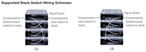
  6. (Optional) In the Select a Cabling Scheme drop-down list, choose the stack cabling scheme, if you want to renumber the stack.

    This item appears only for switches that support stacking, and only if they are connected as shown in one of the following cabling schemes.

    Figure 1. Cabling Schemes
  7. (Optional) In the Select a Top of Stack serial Number drop-down list, choose the serial number of the top-of-stack switch, if you want to renumber the stack.

    This item appears only for switches that support stacking, and only if they are connected as shown in the image.

  8. (Optional) In the Select a License Level drop-down list, choose the stack license level.

    This item appears only for switches that support stacking.

  9. If you made any changes, click Save; otherwise, click Cancel to return to the list and configure other devices.

Step 10

If you selected multiple devices to provision, click Assign for the next device in the list and repeat the configuration steps, until you have done this for all devices.

Step 11

Click Next.

The Provision Templates window appears, where you can specify the values for parameters that were defined in the template.

Step 12

Click the name of a device that you want to configure and follow these steps:

  1. Specify the values for the parameters that were defined in the template, if the device was assigned a configuration template.

    Enter the values for each parameter in the fields for each device. A red asterisk indicates a required field.

  2. If you want to copy the running configuration to the startup configuration on the selected device, check Copy running config to startup config.

  3. If you selected multiple devices to provision, click the next device in the list at the left side of the window and enter the parameter values, until you have done this for all devices.

Step 13

To specify parameter values for all devices in bulk, do the following:

  1. Click Export to save the CSV template file.

  2. Add the values for each of the parameters to the file and save the file.

  3. Click Import.

  4. Drag and drop the file to the drag and drop area, or click where it says "click to select" and select the file.

  5. Click Import.

Step 14

Click Next.

The Summary window appears, where you can view details about the devices and their configuration preview status.

Step 15

Check the Day-0 Config column for each device to see if the configuration preview was successful.

If the preview shows an error, click the Actions link in the error message above the table to see what actions you need to take. You can click an action to open a new tab with the window where a change is needed. You must resolve any issues before claiming the device, to avoid provisioning errors. You may need to go back to the Provision Templates step and change parameter values, change the template, revisit the Design area to update network design settings, or resolve any network connectivity issues. After you have resolved the problem, you can go back to this tab, click Retrying getting Day-0 configuration preview for failed device(s), and click OK.

Step 16

Click the link in the Day-0 Config column to see more information about the device, its configuration, and any configuration preview errors.

Step 17

Click Claim.

Step 18

In the confirmation dialog box, click Yes to claim the devices.


What to do next

To complete the provisioning process, after the device is added to the inventory, go to the Inventory tab, select the device, and choose Actions > Provision > Provision Device. Proceed through all the steps and click Deploy in the Summary step. In the Summary, you can see the remaining network settings that will be pushed to the device. For more information, see Wireless Device Provisioning Overview. This process is required if you intend to push the network settings that you may have configured in the Design area. During Plug and Play provisioning, only the device credentials and the Onboarding Configuration are pushed to the device; no other network settings are pushed until provisioning is completed from Inventory. Additionally, the device is added to Cisco ISE by Cisco DNA Center as a AAA client for RADIUS and TACACS, if these are configured.

Provision a Wireless or Sensor Device

Claiming a wireless device provisions it by assigning a configuration to the device and adding it to the inventory. If you claim a device that has not yet booted for the first time, you are planning the device so that it is automatically provisioned when it boots up.


Note


When Device Controllability is enabled for a device (it is enabled by default), additional configurations are pushed to the device when it is added to the inventory or assigned to a site. For more information, see the Device Controllability section in the Cisco DNA Center Administrator Guide.


This procedure explains how to claim a device from the Plug and Play Devices list. Alternatively, you can claim a device from the device details window by clicking Claim.

Before you begin

  • Ensure that Cisco network devices to be provisioned have a supported software release and are in a factory default state. If you are using a network device that was previously configured or is in an unknown state, see the device clean-up and reset details in the Network Plug and Play Troubleshooting Guide for Cisco DNA Center.

  • Ensure that the devices being provisioned can discover and contact Cisco DNA Center. For more information, see Controller Discovery Prerequisites.

  • Define the site within the network hierarchy. See Network Hierarchy Overview.

  • Define the CLI and SNMP credentials for the devices. See Global Device Credentials Overview.


    Note


    You can claim wireless devices using CLI, SNMPv2c, or SNMPv3 credentials. If you use SNMPv2c, provide both Read Only and Read Write credentials.


  • For provisioning a wireless AP device, ensure that the wireless LAN controller that is managing the wireless AP has been added to the inventory and assigned to the site where the wireless device is to be assigned. This is not needed for a Mobility Express AP.

  • Optionally, ensure that the software images for any Cisco Catalyst 9800-CL devices to be provisioned are uploaded and marked as golden in the Image Repository, if you want to deploy images. See Import a Software Image.


    Note


    The image deployment process used by Plug and Play during Day-0 provisioning is not the same as that used when updating a device image later, which is described in Provision a Software Image. During Plug and Play provisioning, there are no device prechecks, auto flash cleanup, or postchecks done, as it is expected that devices are in the factory default state.


  • For provisioning a sensor device, ensure that the sensor is reachable through the Cisco DNA Center enterprise IP address (private/enp9s0). A DHCP option 43 string makes the device reachable in unclaimed mode in Cisco DNA Center; however, to claim the device, it must be reachable from the interface enp9s0 IP address. In the DHCP server, configure the NTP server (DHCP option 42) and the vendor-specific DHCP option 43 with ACSII value "5A1D;B2;K4;I172.16.x.x;J80;", where 172.16.x.x is the virtual IP address of Cisco DNA Center associated with the enp9s0 interface.

  • Define wireless radio frequency profiles for wireless AP devices, except for Mobility Express APs. See Create a Wireless Radio Frequency Profile.

  • For Mobility Express APs, define an IP address pool and a management interface. See Configure IP Address Pools.

Procedure


Step 1

Click the menu icon () and choose Provision > Plug and Play.

Step 2

View the devices in the table.

You can use the Filter or Find option to find specific devices.

Step 3

Check the check box next to one or more wireless devices that you want to claim.

Step 4

From the menu bar above the device table, choose Actions > Claim.

The Claim Devices window opens, showing the first step, Assign Site. If, instead, you see a window that shows mandatory tasks such as defining a site and defining device credentials, you must click Add Site to define a site, and Add device credentials to define device credentials. These are prerequisites for the claim process and, after these tasks are completed, you can return to claiming a device by clicking Refresh in this window.

Step 5

(Optional) Change the device name, if needed, in the first column.

Step 6

(Optional) Change the device type, if needed, in the second column. You can choose AP or ME (Mobility Express), depending on which mode the device is using.

Choosing the wrong mode causes an error provisioning the device. This item does not appear for wireless LAN controller or sensor devices.

Step 7

From the Select a Site drop-down list, choose a site and floor to assign to each device. AP devices must be assigned to a floor with a wireless controller.

To apply the same site as the first device to all other devices, check the Apply Site to All check box. To assign the site from any device to some other devices, click Assign this Site to Other Devices, choose the devices, and click Assign. Wireless devices can be assigned only to floors within a building, not to the building itself.

Step 8

Click Next.

The Assign Configuration window appears.

Step 9

(Optional) You can change which columns are displayed in the table by clicking the three dots at the right end of the table headings and choosing the desired columns. Click Apply to save the changes.

Step 10

In the Configuration column, click Assign for the device that you want to configure and follow these steps:

  1. View the device configuration summary and click Cancel if no changes are needed.

  2. (Optional) In the Device Name field, change the device name, if needed.

  3. For an AP device, in the Radio Frequency Profile drop-down list, choose a radio frequency profile to apply to the device. This may be set if you designated one profile as a default.

  4. For a wireless LAN controller, enter values in the following fields: Wireless management IP, Subnet mask, Gateway, IP interface name, and optionally, VLAN ID.

  5. For a Mobility Express device, enter values in the following fields: Wireless management IP, Subnet mask, and Gateway.

  6. For a wireless sensor device, in the Sensor Settings drop-down list, choose the sensor device profile (backhaul) to apply to the device.

    Note


    For Cisco Aironet 1800s Active Sensor earlier than Release 1.3.1.2, make sure that you do not choose the sensor device profile CiscoProvisioningSSID. Instead, choose your own SSID for backhaul purposes.

  7. If you made any changes, click Save; otherwise, click Cancel to return to the list and configure other devices.

  8. You can apply a configuration that you assigned to one device to other devices of the same type by clicking Apply … to Other Devices in the Actions column.

Step 11

If any devices are a Cisco Catalyst 9800-CL Wireless Controller, click Assign next to Image in the Configuration column and follow these steps:

  1. (Optional) In the Image drop-down list, choose a golden software image to apply to the device. If there is only one golden image for this device type in the image repository, it is chosen by default.

  2. Click Save.

Step 12

If you selected multiple devices to provision, click Assign for the next device in the list and repeat the configuration, until you have done this for all devices.

Step 13

Click Next.

The Summary window appears, where you can view details about the devices and configuration.

Step 14

Check the Day-0 Config column for each device to see if the configuration preview was successful.

If the preview shows an error, you can click the Actions link in the error message above the table to see what actions you need to take. You can click an action to open a new tab with the window where a change is needed. You must resolve any issues before claiming the device, to avoid provisioning errors. You may need to go back to the Assign Configuration step and change the configuration, revisit the Design area to update network design settings, or resolve any network connectivity issues. After you have resolved the problem, you can go back to this tab, click Retrying getting Day-0 configuration preview for failed device(s), and click OK. Ensure that the wireless LAN controller that is managing a device has been added to the inventory and assigned to the site where the wireless device is assigned.

Step 15

Click Claim.

Step 16

In the confirmation dialog box, click Yes to claim the devices and start the provisioning process.


What to do next

To complete the provisioning process, after the device is added to the inventory, go to the Inventory tab, select the device, and choose Actions > Provision > Provision Device. Proceed through all the steps and click Deploy in the Summary step. In the Summary, you can see the remaining network settings that will be pushed to the device. For more information, see Wireless Device Provisioning Overview. This process is required if you intend to push the network settings that you may have configured in the Design area. During Plug and Play provisioning, only the device credentials and the Onboarding Configuration are pushed to the device; no other network settings are pushed until provisioning is completed from Inventory. Additionally, the device is added to Cisco ISE by Cisco DNA Center as a AAA client for RADIUS and TACACS, if these are configured.

Provision a Cisco DNA Traffic Telemetry Appliance

This procedure explains how to claim a Cisco DNA Traffic Telemetry Appliance from the Plug and Play Devices list.

Before you begin

  • Ensure that the Cisco network devices to be provisioned have a supported software release and are in a factory default state. If you are using a network device that was previously configured or is in an unknown state, see the device clean-up and reset details in Network Plug and Play Troubleshooting Guide for Cisco DNA Center.

  • Ensure that the devices being provisioned can discover and contact Cisco DNA Center.

  • Define the site within the network hierarchy. See Network Hierarchy Overview.

  • Define the CLI and SNMP credentials for the devices. If you are using SNMPv2c, you must provide both Read and Write credentials.


    Note


    SNMPv3 limitations:
    • Supports SHA for Auth and AES128 for privacy.

    • Does not support MD5.


  • If you want to deploy images, ensure that the software images for the devices to be provisioned are uploaded and marked as golden in the Image Repository. See Import a Software Image.


    Note


    The image deployment process that Plug and Play uses during Day-0 provisioning is not the same as the deployment process used when updating a device image later. For information, see Provision a Software Image. During provisioning, Plug and Play performs no device prechecks, auto flash cleanup, or postchecks. The device must be in the factory default state.


  • Define network profiles for the devices. See Create Network Profile for Cisco DNA Traffic Telemetry Appliance.

Procedure


Step 1

Click the menu icon () and choose Provision > Plug and Play.

Step 2

View the devices in the table.

You can use the Filter or Find option to find the Cisco DNA Traffic Telemetry Appliance.

Step 3

Check the check box next to one or more devices that you want to claim.

Step 4

From the menu bar above the device table, choose Actions > Claim.

The Claim Devices window opens, showing the first step, Assign Site. If instead, you see a window that shows mandatory tasks such as defining a site and defining device credentials, you must click Add Site to define a site, and Add device credentials to define device credentials. These mandatory tasks are prerequisites for the claim process. After these tasks are completed, you can return to claiming a device by clicking Refresh in this window.

Step 5

(Optional) Change the device hostname, if needed, in the first column.

Step 6

From the Select a Site drop-down list, choose a site to assign to each device.

To apply the same site as the first device to all other devices, check the Apply Site to All check box. To assign the site from any device to some other devices, click Assign this Site to Other Devices, choose the devices, and click Assign.

Step 7

Click Next.

The Assign Configuration window appears.

Step 8

In the Configuration column, click Assign for the device that you want to configure and follow these steps:

  1. View the device configuration summary and, if no changes are needed, click Cancel.

  2. (Optional) In the Device Name field, change the device hostname, if needed.

  3. (Optional) In the Image drop-down list, choose a golden software image to apply to the device. If there is only one golden image for this device type in the image repository, it is chosen by default.

  4. If you made any changes, click Save. Otherwise, click Cancel to return to the list and configure other devices.

Step 9

If you selected multiple devices to provision, click Assign for the next device in the list. Repeat the configuration steps until you have configured all devices.

Step 10

Click Next.

The Summary window appears, where you can view details about the devices and their configuration preview status.

Step 11

Check the Day-0 Config column for each device to see if the configuration preview was successful.

If the preview shows an error, click the Actions link in the error message above the table to see what actions you need to take. Click an action to open a new tab with the window where a change is needed. To avoid provisioning errors, you must resolve any issues before claiming the device. You may need to revisit the Design area to update network design settings or resolve any network connectivity issues. After you resolve the problem, return to this tab, click Retrying getting Day-0 configuration preview for failed device(s), and click OK.

Step 12

Click the link in the Day-0 Config column to see more information about the device, its configuration, and any configuration preview errors.

Step 13

Click Claim.

Step 14

In the confirmation dialog box, click Yes to claim the devices.


What to do next

To complete the provisioning process, after the device is added to the inventory, go to the Inventory tab, select the device, and choose Actions > Provision > Provision Device. Proceed through all the steps and click Deploy in the Summary step. In the Summary window, you can see the remaining network settings that are pushed to the device. For more information, see Wireless Device Provisioning Overview. This process is required if you intend to push the network settings that you may have configured in the Design area. During Plug and Play provisioning, only the device credentials and the Onboarding Configuration are pushed to the device; no other network settings are pushed until provisioning is completed from Inventory.

Delete a Device

Deleting a device removes it from the Plug and Play database but does not reset the device. Use Reset if you want to reset a device that is in the Error state.

This procedure explains how to delete a device from the Plug and Play Devices list. Alternatively, you can delete a device from the device details window by clicking Delete.


Note


If a device is in the Provisioned state, it can be deleted only from the Inventory tab.

Procedure


Step 1

Click the menu icon () and choose Provision > Plug and Play.

Step 2

View the devices in the table.

You can filter on device state by using one of the Device State buttons, or use the Filter option to find specific devices. Click Refresh to refresh the device list.

Step 3

Check the check box next to one or more devices that you want to delete.

Step 4

From the menu bar above the device table, choose Actions > Delete.

Step 5

Click Yes to confirm that you want to delete the devices.


Reset a Device

Resetting a device applies only to devices in the Error state and resets its state to Unclaimed and reloads the device, but does not remove it from the Plug and Play database. Use Delete if you want to delete a device.


Note


If the saved configuration on the device is the factory default or a similar minimal configuration, then this option causes the device to restart the provisioning process. However, if the device has a previously saved startup configuration, then this could prevent the device from restarting the provisioning process and it will need to be reset to factory defaults. On wireless and sensor devices, only the device state is reset and the device is not reloaded.

This procedure shows how to reset a device from the Plug and Play Devices list. Alternatively, you can reset it from the device details window by clicking Reset.

Procedure


Step 1

Click the menu icon () and choose Provision > Plug and Play.

Step 2

View the devices in the table.

You can filter on device state by using one of the Device State buttons, or use the Filter option to find specific devices. Click Refresh to refresh the device list.

Step 3

Check the check box next to one or more devices that you want to reset.

Step 4

Click Actions > Reset in the menu bar above the device table.

A confirmation dialog box is displayed.

Step 5

Choose one of the following options:

  • Reset and keep current claim parameters—Keep the current claim parameters and the device goes to the Planned state.

  • Reset and remove all claim parameters—Remove the current claim parameters and the device goes to the Unclaimed state.

Step 6

Click Reset.