Prepare the Appliance for Configuration

Preparation for Appliance Configuration Overview

Before you can successfully configure your Cisco DNA Center appliance, first complete the following tasks:

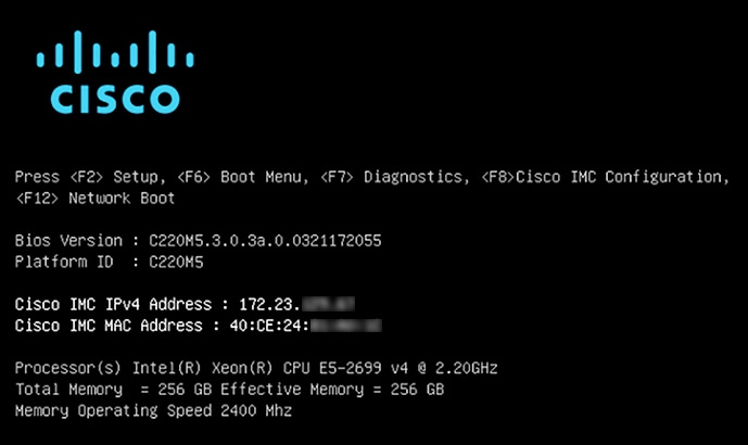
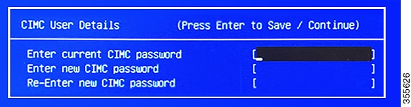
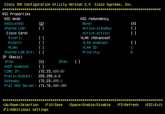
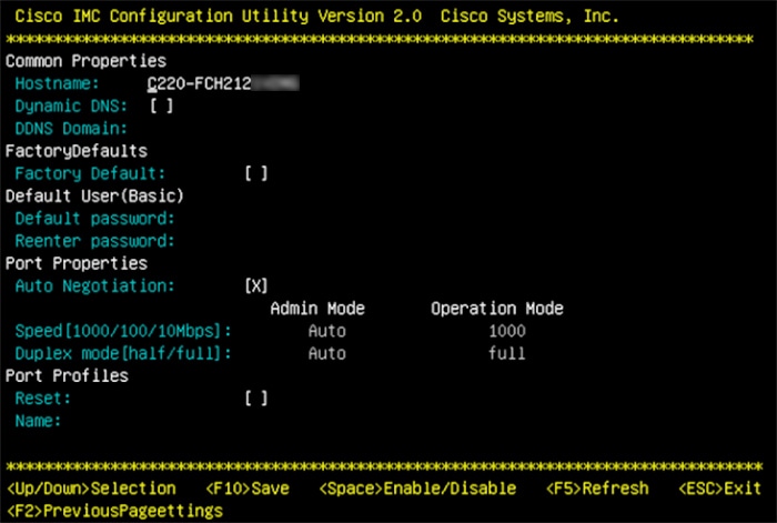
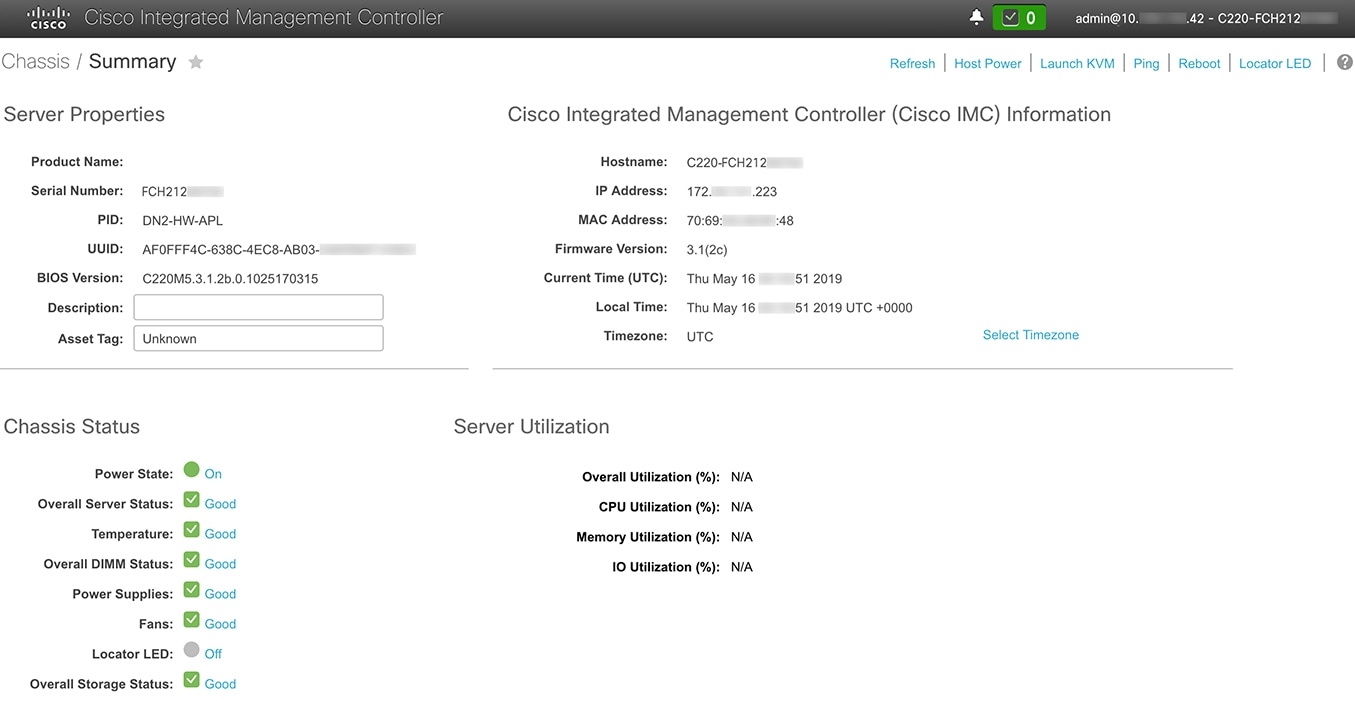
  1. Enable browser access to the appliance's Cisco IMC (see Enable Browser Access to Cisco Integrated Management Controller).

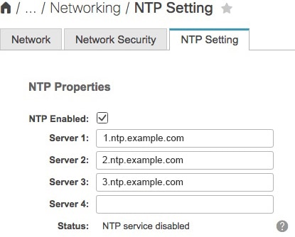
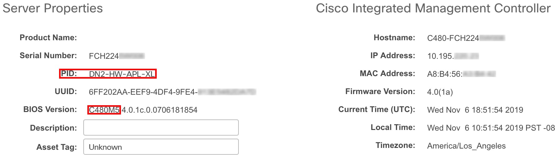
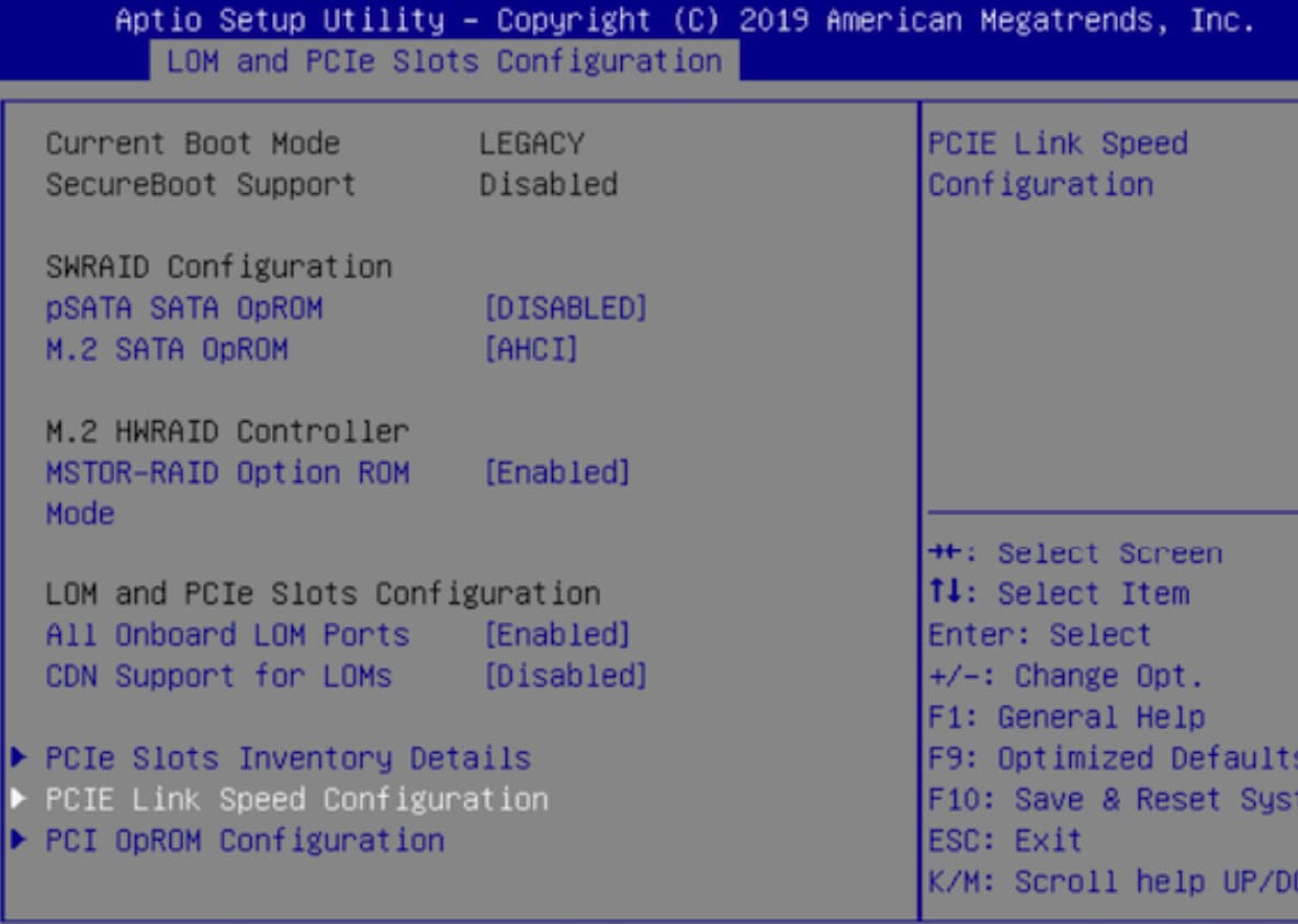
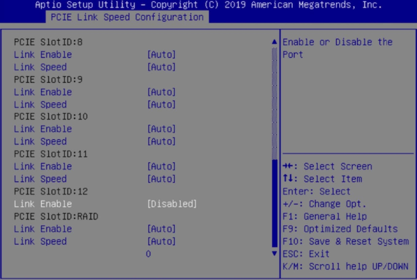
  2. Use Cisco IMC to check and adjust important hardware and switch settings (see Execute Preconfiguration Checks).

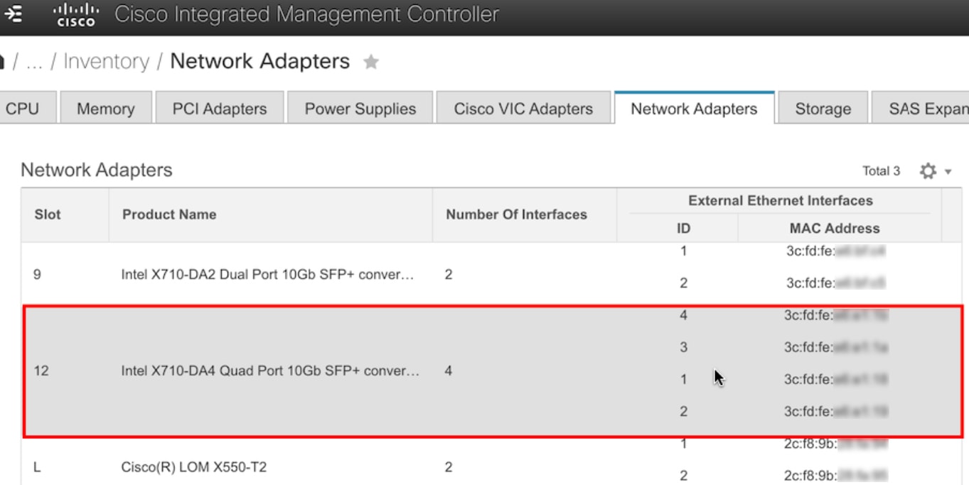
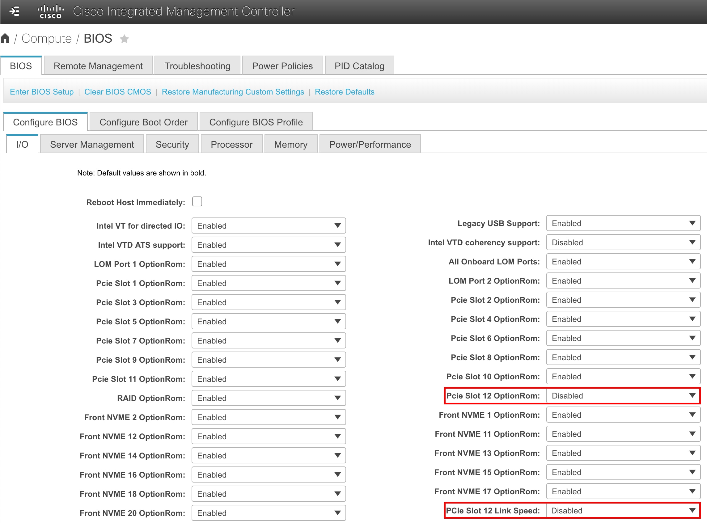
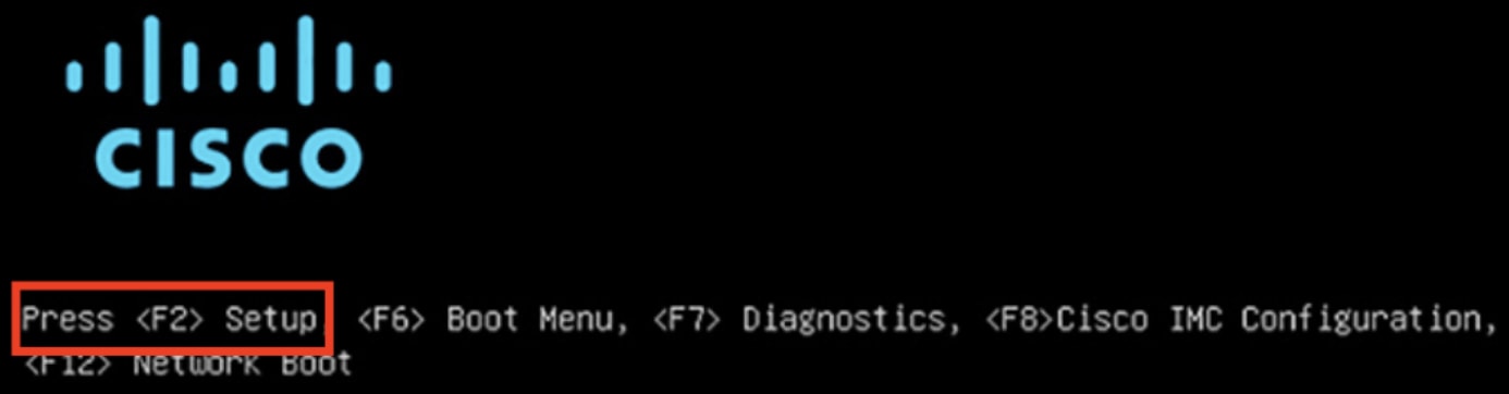
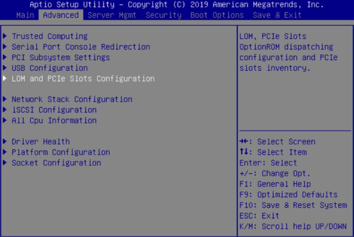
  3. If the Intel X710-DA4 network interface card (NIC) that shipped with your appliance is currently enabled, you need to disable it (see Disable the Network Interface Card).

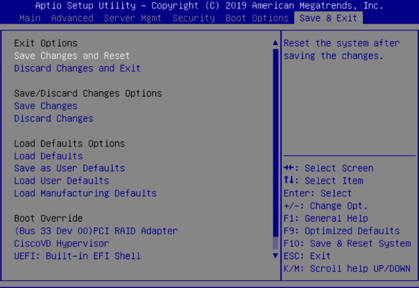
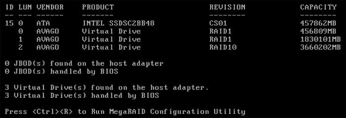
  4. Cisco DNA Center software is preinstalled on your appliance, but you may need to reinstall the software in certain situations (such as before you change the current cluster link configuration). If this is the case, you must also complete the tasks described in Reimage the Appliance.


    Note

    If you do not need to reimage your appliance, proceed to the "Appliance Configuration Overview" topic specific to the configuration wizard you want to use:


Enable Browser Access to Cisco Integrated Management Controller

After installing the appliance, as described in Appliance Installation Workflow, use the Cisco IMC configuration utility to assign an IP address and gateway to the appliance's CIMC port. This gives you access to the Cisco IMC GUI, which you should use to configure the appliance.

After you complete the Cisco IMC setup, log in to Cisco IMC and run the tasks listed in Execute Preconfiguration Checks to ensure correct configuration.


Tip

To help ensure the security of your deployment, Cisco IMC prompts you to change the Cisco IMC user's default password when you boot the appliance for the first time. To change the Cisco IMC user password later, use the Cisco IMC GUI, as follows:

  1. From the top-left corner of the GUI, click the Toggle Navigation icon () and then choose Admin > User Management.

    The Local User Management tab should already be selected.

  2. Check the check box for user 1, and then click Modify User.

    The Modify User Details dialog box opens.

  3. Check the Change Password check box.

  4. Enter and confirm the new password, and then click Save.


Procedure


Step 1

Access the appliance console by attaching either of the following:

  • A KVM cable to the KVM connector on the appliance's front panel (component 11 on the front panel illustrated in Front and Rear Panels)
  • A keyboard and monitor to the USB and VGA ports on the appliance's rear panel (components 2 and 5, respectively, on the rear panel illustrated in Front and Rear Panels).
Step 2

Make sure that the appliance's power cord is plugged in and the power is on.

Step 3

Press the Power button on the front panel to boot the appliance.

The Cisco IMC configuration utility boot screen should be displayed, as shown below.

Step 4

As soon as the boot screen is displayed, press F8 to perform Cisco IMC configuration.

The CIMC configuration utility displays the CIMC User Details screen, as shown below.


Step 5

Enter the default CIMC user password (the default on a new appliance is password) in the Enter current CIMC Password field.

Step 6

Enter and confirm the new CIMC user password in the Enter new CIMC password and Re-Enter new CIMC password fields.

When you press Enter after entering the new password in the Re-Enter new CIMC password field, the Cisco IMC configuration utility displays the NIC Properties screen, as shown below.

Step 7

Perform the following actions:

  • NIC mode: Select Dedicated.

  • IP (Basic): Select IPV4.

  • CIMC IP: Enter the IP address of the CIMC port.

  • Prefix/Subnet: Enter the subnet mask for the CIMC port IP address.

  • Gateway: Enter the IP address of your preferred default gateway.

  • Pref DNS Server: Enter the IP address of your preferred DNS server.

  • NIC Redundancy: Select None.

Step 8

Press F1 to specify Additional settings.

The Cisco IMC configuration utility displays the Common Properties screen, as shown below.

Step 9

Perform the following actions:

  • Hostname: Enter a hostname for CIMC on this appliance.

  • Dynamic DNS: Uncheck the check box to disable this feature.

  • Factory Defaults: Uncheck the check box to disable this feature.

  • Default User (Basic): Leave these fields blank.

  • Port Properties: Enter new settings or accept the defaults shown in these fields.

  • Port Profiles: Uncheck the check box to disable this feature.

Step 10

Press F10 to save the settings.

Step 11

Press Escape to exit and reboot the appliance.

Step 12

After the settings are saved and the appliance finishes rebooting, open a compatible browser on a client machine with access to the subnet on which the appliance is installed, and enter the following URL:

https://CIMC_ip_address, where CIMC_ip_address is the Cisco IMC port IP address that you entered in Step 7.

Your browser displays a main Cisco IMC GUI login window similar to the one shown below.

Step 13

Log in using the Cisco IMC user ID and password you set in Step 5.

If the login is successful, your browser displays a Cisco Integrated Management Controller Chassis Summary window similar to the one shown below.


Execute Preconfiguration Checks

After installing the appliance (as described in Appliance Installation Workflow) and setting up access to the Cisco IMC GUI (as described in Enable Browser Access to Cisco Integrated Management Controller), use Cisco IMC to perform the following preconfiguration tasks, which help ensure correct configuration and deployment:

  1. Synchronize the appliance hardware with the Network Time Protocol (NTP) servers you use to manage your network. These must be the same NTP servers whose hostnames or IPs you gathered for use when planning your implementation, as explained in Required IP Addresses and Subnets. This is a critical task that ensures that your Cisco DNA Center data is synchronized properly across the network.

  2. Reconfigure the switches connected to the 10-Gbps appliance ports to support higher throughput settings.

Procedure


Step 1

Log in to the appliance's Cisco IMC using the Cisco IMC IP address, user ID, and password you set in Enable Browser Access to Cisco Integrated Management Controller.

If the login is successful, your browser displays the Cisco Integrated Management Controller Chassis Summary window, as shown below.

Step 2

Synchronize the appliance's hardware with the Network Time Protocol (NTP) servers you use to manage your network, as follows:

  1. From the top-left corner of the Cisco IMC GUI, click the Toggle Navigation icon ().

  2. From the Cisco IMC menu, select Admin > Networking, and then choose the NTP Setting tab.

  3. Make sure that the NTP Enabled check box is checked and enter up to four NTP server host names or addresses in the numbered Server fields, as shown in the example below.

  4. Click Save Changes. Cisco IMC validates your entries and then begins to synchronize the time on the appliance's hardware with the time on the NTP servers.

    Note 

    Unlike the previous generation of Cisco DNA Center appliances, second generation appliances do not use a virtual interface card (VIC). You do not need to configure the network interface card (NIC) that comes installed on your second generation appliance to support high throughput in Cisco IMC, as this is already enabled by default.

Step 3

Reconfigure your switches to match the high-throughput settings on the appliance, as follows:

  1. Using a Secure Shell (SSH) client, log in to the switch to be configured and enter EXEC mode at the switch prompt.

  2. Enter the following series of commands to configure the switch port:

    MySwitch#Config terminal
    MySwitch(config)#interface tengigabitethernet 1/1/3 
    MySwitch(config-if)#switchport mode access 
    MySwitch(config-if)#switchport access vlan 99 
    MySwitch(config-if)#speed auto 
    MySwitch(config-if)#duplex full 
    MySwitch(config-if)#mtu 1500 
    MySwitch(config-if)#no shut 
    MySwitch(config-if)#end 
    MySwitch(config)#copy running-config startup-config 
    Note 

    These commands are examples only.

    Important 

    The switch port on Cisco DNA Center second generation appliances must be set to access mode in order to function properly. Trunk mode is not supported, as it is on first generation appliances.

  3. Run the show interface tengigabitethernet portID command and verify that the port is connected, running, and has the correct MTU, duplex, and link-type settings in the command output. For example:

    MySwitch#show interface tengigabitethernet 1/1/3 
    TenGigabitEthernet1/1/3 is up, line protocol is up (connected) 
      Hardware is Ten Gigabit Ethernet, address is XXXe.310.8000 (bia XXX.310.8000)
      MTU 1500 bytes, BW 10000000 Kbit/sec, DLY 10 usec, 
         reliability 255/255, txload 1/255, rxload 1/255 
      Encapsulation ARPA, loopback not set 
      Keepalive not set 
      Full-duplex, 10GB/s, link type is auto, media type is SFP-10Gbase-SR
  4. Run the show run interface tengigabitethernet portID command to configure the switch ports where the cables from the Intel X710-DA2 NIC ports are connected. For example:

    MySwitch#show run interface tengigabitethernet 1/1/3 
    Building configuration... 
    Current configuration : 129 bytes 
    ! interface TenGigabitEthernet1/1/3 
     switchport access vlan 99 
     ip device tracking maximum 10 
    end 
    
    MySwitch#
  5. Run the show mac address-table interface tengigabitethernet portID command and verify the MAC address from the command output. For example:

    MySwitch#show mac address-table interface tengigabitethernet 1/1/3 
               Mac Address Table 
    ––––––––––––––––––––––––––––––––––––––––––-- 
    Vlan     Mac Address       Type      Ports 
    ––--     ––––––––––-       –––-      –––-- 
    99       XXXe.3161.1000    DYNAMIC   Te1/1/3 
    Total Mac Addresses for this criterion: 1 
    
    MySwitch#

What to do next

When this task is complete, do one of the following:

Disable the Network Interface Card

If your appliance ships with the Intel X710-DA4 network interface card (NIC) enabled, you must disable it by completing the following procedure. If you do not disable the card, your appliance will contain four extra interfaces, which could negatively affect your configuration.

Procedure


Step 1

Confirm that you have a Cisco DNA Center appliance and that it has the Intel X710-DA4 NIC installed.

  1. Log in to the appliance's Cisco IMC.

  2. In the Summary window's Server Properties area, confirm that the following values are set:

    • PID: DN2-HW-APL for a 44 core appliance, DN2-HW-APL-L for a 56 core appliance, or DN2-HW-APL-XL for a 112 core appliance (see the following example).

    • BIOS Version: This value should start with either C220M5 for a 44 and 56 core appliance or C480M5 for a 112 core appliance (see the following example).

  3. Choose > Chassis > Inventory > Network Adapters.

  4. In the Network Adapters table, confirm that the Intel X710-DA4 Quad Port network adapter is listed for one of the following slots:

    • For a 44 or 56 core appliance, Slot 2.

    • For a 112 core appliance, Slot 12 (see the following example).

Step 2

Confirm that the your appliance's PCIe card is disabled:

  1. Choose > Compute.

    The BIOS > Configure BIOS > I/O tab opens.

  2. Set the following parameters to Disabled, then click Save:

    • For a 44 or 56 core appliance, PCIe Slot 2 OptionROM and PCIe Slot 2 Link Speed.

    • For a 112 core appliance, PCIe Slot 12 OptionROM and PCIe Slot 12 Link Speed (see the following example).

  3. Do one of the following:

    • If you were able to set these two parameters to Disabled for your appliance, reboot your appliance and then proceed with its configuration. You do not need to complete the rest of this procedure.

    • If you have a 112 core appliance and only see one of these parameters displayed in the I/O tab, proceed to Step 3 and complete the rest of this procedure.

Step 3

Boot into your appliance's BIOS:

  1. From Cisco IMC, start a KVM session.

  2. Power cycle the appliance by clicking the Host Power link and then choosing Power Cycle.

  3. During startup, press the F2 key as soon as you see the following screen to boot into your appliance's BIOS and open the Aptio Setup Utility.

Step 4

Disable the PCIe card:

  1. From the Aptio Setup Utility's Main tab, open the Advanced tab and then choose LOM and PCIe Slots Configuration.

  2. In the LOM and PCIe Slots Configuration tab, choose PCIE Link Speed Configuration.

  3. In the PCIE Link Speed Configuration tab, scroll down to PCIE SlotID: 12's Link Enable option and then press Enter.

  4. Choose Disable, then press ENTER.

    Your screen should look like the following example:

  5. Press the ESC key twice to return to the main BIOS menu, then open the Save & Exit tab.

  6. Choose the Save Changes and Reset option, then press Enter.

    Your appliance reboots and opens the configuration wizard. Proceed with the configuration of your appliance.

    Important 

    After you have disabled your appliance's NIC, if you reset your appliance to the default settings in Cisco IMC ( > Admin > Utilities > Reset to factory Default), you will need to complete this procedure again.


Reimage the Appliance

Situations that require you to reimage your Cisco DNA Center appliance, such as recovering from a backup or changing your cluster link configuration, might arise. To do so, complete the following procedure.

Procedure


Step 1

Download the Cisco DNA Center ISO image and verify that it is a genuine Cisco image.

See Verify the Cisco DNA Center ISO Image.

Step 2

Create a bootable USB drive that contains the Cisco DNA Center ISO image.

See Create a Bootable USB Drive.

Step 3

Reinitialize the virtual drives that are managed by your appliance’s RAID controller:

Step 4

Reinstall Cisco DNA Center onto your appliance.

See Install the Cisco DNA Center ISO Image.


Verify the Cisco DNA Center ISO Image

Prior to deploying Cisco DNA Center, we strongly recommend that you to verify that the ISO image you downloaded is a genuine Cisco image.

Before you begin

Obtain the location of the Cisco DNA Center ISO image (through email or by contacting the Cisco support team).

Procedure


Step 1

Download the Cisco DNA Center ISO image (.iso) from the location specified by Cisco.

Step 2

Download the Cisco public key (cisco_image_verification_key.pub) for signature verification from the location specified by Cisco.

Step 3

Download the secure hash algorithm (SHA512) checksum file for the ISO image from the location specified by Cisco.

Step 4

Obtain the ISO image's signature file (.sig) from Cisco support through email or by download from the secure Cisco website (if available).

Step 5

(Optional) Perform an SHA verification to determine whether the ISO image is corrupted due to a partial download.

Run one of the following commands (depending upon your operating system):

  • On a Linux system: sha512sum ISO-image-filename

  • On a Mac system: shasum -a 512 ISO-image-filename

Microsoft Windows does not include a built-in checksum utility, but you can install a utility from Microsoft at this link: http://www.microsoft.com/en-us/download/details.aspx?id=11533.

Compare the output of the command you run (or Microsoft Windows utility) to the SHA512 checksum file downloaded in Step 3. If the command output fails to match, download the ISO image again and run the appropriate command a second time. If the output still fails to match, contact Cisco support.

Step 6

Verify that the ISO image is genuine and from Cisco by verifying its signature:

openssl dgst -sha512 -verify cisco_image_verification_key.pub -signature signature-filename ISO-image-filename

Note 

This command works in both MAC and Linux environments. For Windows, you need to download and install OpenSSL (available here) if you have not already done so.

If the ISO image is genuine, running this command should display a Verified OK message. If this message fails to appear, do not install the ISO image and contact Cisco support.

Step 7

After confirming that you have downloaded a Cisco ISO image, create a bootable USB drive that contains the Cisco DNA Center ISO image. See Create a Bootable USB Drive.


Create a Bootable USB Drive

Complete one of the following procedures to create a bootable USB drive from which you can install the Cisco DNA Center ISO image.

Before you begin:

  • Download and verify your copy of the Cisco DNA Center ISO image. See Verify the Cisco DNA Center ISO Image.

  • Confirm that the USB flash drive you are using has a capacity of at least 32 GB.

Using Etcher

Procedure

Step 1

Download and install Etcher (Version 1.3.1 or later), an open-source freeware utility that allows you to create a bootable USB drive on your laptop or desktop.

Linux, macOS, and Windows versions of Etcher are currently available. You can download a copy at https://www.balena.io/etcher/.

Note 

Use only the Windows version of Etcher on machines running Windows 10, as there are known compatibility issues with older versions of Windows.

Step 2

From the machine on which you installed Etcher, connect a USB drive and then start Etcher.

Step 3

In the top-right corner of the window, click and verify that the following Etcher settings are set:

  • Auto-unmount on success

  • Validate write on success

Step 4

Click Back to return to the main Etcher window.

Step 5

Click Select Image.

Step 6

Navigate to the Cisco DNA Center ISO image you downloaded previously, select it, and then click Open.

The name of the USB drive you connected should be listed under the drive icon (). If it is not:

  1. Click Select drive.

  2. Click the radio button for the correct USB drive, and then click Continue.

Step 7

Click Flash! to copy the ISO image to the USB drive.

Etcher configures the USB drive as a bootable drive with the Cisco DNA Center ISO image installed.


Using the Linux CLI

Procedure

Step 1

Verify that your USB flash drive is recognized by your machine:

  1. Insert a flash drive into your machine's USB port.

  2. Open a Linux shell and run the following command: lsblk

    The command lists the disk partitions that are currently configured on your machine, as illustrated in the following example:

    $ lsblk
    NAME MAJ:MIN RM SIZE RO TYPE MOUNTPOINT
    sda 8:0 0 446.1G 0 disk
    ├─sda1 8:1 0 1M 0 part
    ├─sda2 8:2 0 28.6G 0 part /
    ├─sda3 8:3 0 28.6G 0 part /install2
    ├─sda4 8:4 0 9.5G 0 part /var
    ├─sda5 8:5 0 30.5G 0 part [SWAP]
    └─sda6 8:6 0 348.8G 0 part /data
    sdb 8:16 0 1.8T 0 disk
    ├─sdb1 8:17 0 426.1G 0 part /data/maglev/srv/fusion
    └─sdb2 8:18 0 1.3T 0 part /data/maglev/srv/maglev-system
    sdc 8:32 0 3.5T 0 disk
    └─sdc1 8:33 0 3.5T 0 part /data/maglev/srv/ndp
    sdd 8:48 1 28.7G 0 disk
    └─sdd1 8:49 1 12G 0 part
  3. Confirm that an sdd partition (which indicates the presence of a USB flash drive) is listed.

Step 2

Burn the Cisco DNA Center ISO image you downloaded previously onto your USB flash drive: time sudo dd if=/data/tmp/ISO-image-filename of=/dev/flash-drive-partition bs=4M && sync

For example, to create a bootable USB drive using an ISO image named CDNAC-SW-1.330.iso, you would run the following command: time sudo dd if=/data/tmp/CDNAC-SW-1.330.iso of=/dev/sdd bs=4M && sync


Using the Mac CLI

Procedure

Step 1

Determine the disk partition associated with your USB flash drive:

  1. Open a Terminal window and run the following command: diskutil list

    The command lists the disk partitions that are currently configured on your machine.

  2. Insert a flash drive into your machine's USB port and run the diskutil list command a second time.

    The partition that was not listed the first time you ran this command corresponds to your flash drive. For example, let's assume that your flash drive's partition is /dev/disk2.

Step 2

Unmount the flash drive's partition: diskutil unmountDisk flash-drive-partition

Continuing our example, you would enter diskutil unmountDisk /dev/disk2

Step 3

Using the Cisco DNA Center ISO image you downloaded previously, create a disk image: hdiutil convert -format UDRW -o Cisco-DNA-Center-version ISO-image-filename

Continuing our example, let's assume that you are working with a Cisco DNA Center ISO image named CDNAC-SW-1.330.iso. You would run the following command, which creates a macOS disk image named CDNAC-1.330.dmg: hdiutil convert -format UDRW -o CDNAC-1.330 CDNAC-SW-1.330.iso

Important 

Ensure that the ISO image does not reside on a Box partition.

Step 4

Create a bootable USB drive: sudo dd if=macOS-disk-image-filename of=flash-drive-partition bs=1m

Continuing our example, you would run the following command: sudo dd if=CDNAC-1.330.dmg of=/dev/disk2 bs=1m

The ISO image is about 18 GB in size, so this can take around an hour to complete.


Reinitialize the Virtual Drives on a 44 or 56 Core Appliance

Complete the following procedure to reinitialize the virtual drives on your 44 or 56 core Cisco DNA Center appliance.

Procedure


Step 1

Log in to Cisco IMC and start a KVM session.

Step 2

Power on or power cycle the appliance by choosing one of the following menu options:

  • Power > Power On System

  • Power > Power Cycle System (cold boot)

As your appliance reboots, a screen that lists every drive on the appliance (both physical and virtual) will appear.

Step 3

As soon as you see this screen, press Ctrl + R to run the MegaRAID Configuration Utility.

If you wait too long to press Ctrl + R, this screen will disappear. To get back to this screen, choose Power > Reset System (warm boot) from the KVM menu to reboot your appliance.

Step 4

Select a drive’s entry (for example, ID: 0, 446.102 GB) and then press F2.

This opens the drive’s Advanced Properties screen.

Step 5

In the resulting menu, choose Initialization > Fast Initialization.

Step 6

Repeat Steps 2 through 5 for the other virtual drives on your appliance.


Reinitialize the Virtual Drives on a 112 Core Appliance

Complete the following procedure to reinitialize the virtual drives on your 112 core Cisco DNA Center appliance.

Procedure


Step 1

Log in to Cisco IMC and start a KVM session.

Step 2

Power on or power cycle the appliance by choosing one of the following menu options:

  • Power > Power On System

  • Power > Power Cycle System (cold boot)

As your appliance reboots, a screen that lists every drive on the appliance (both physical and virtual) will appear.

Step 3

As soon as you see this screen, press F2 to open the Aptio Setup Utility main page.

If you wait too long to press F2, this screen will disappear. To get back to this screen, choose Power > Reset System (warm boot) from the KVM menu to reboot your appliance.

Step 4

Enable the physical drives on your appliance for configuration as virtual drives:

  1. From the Aptio Setup Utility menu, choose Advanced > AVAGO MegaRAID <Cisco 12G Modular Raid Controller with 4GB cache (max 26 drives)> Configuration Utility - 07.01.12.12 to open the Avago MegaRAID Configuration Utility main page.

  2. Choose Main Menu > Configuration Management.

  3. Choose Clear Configuration.

    You will be asked to confirm the deletion of the virtual drives that are associated with your appliance.

  4. Choose Enabled, then choose Yes, and then choose OK.

  5. Return to the Avago MegaRAID Configuration Utility main page and then choose Configure from the Actions area.

  6. From the Configuration Management page, choose Make Unconfigured Good.

  7. At the bottom of the Make Unconfigured Good page, choose Check All to enable all of the virtual drives and then choose OK.

  8. Choose Enabled, then choose Yes, and then choose OK.

Step 5

Configure the virtual drive that your appliance will use as the boot drive:

  1. Return to Cisco IMC and choose Storage > Cisco 12G Modular Raid Controller with 4GB cache (max 26 drives) (RAID) from the navigation pane.

    The Controller Info tab opens, by default.

  2. Click the Create Virtual Drive from Unused Physical Drives link.

  3. From the RAID Level drop-down list, choose 1.

  4. In the Physical Drives table, check the check box for drives 1 and 2 and then click >> to configure them as a drive group that is listed in the Drive Groups table.

  5. In the Drive Groups table, check the drive group’s check box.

  6. In the Virtual Drive Properties area:

    1. Enter Maglev as the name for the virtual drive.

    2. From the Write Policy drop-down list, choose Write Through if this option is not already set.

    3. Click Create Virtual Drive.

  7. Click the Virtual Drive Info tab, check the check box for the drive you just created (virtual drive 0), and then click Initialize.

    The Initialize Virtual Drive dialog box opens.

  8. From the Initialize Type drop-down list, choose Full Initialize and then click Initialize VD.

  9. Check the check box for the drive, click Set as Boot Drive, and then click OK to confirm.

Step 6

Configure the virtual drive that your appliance will use for NDP:

  1. Click the Controller Info tab and then click the Create Virtual Drive from Unused Physical Drives link.

  2. From the RAID Level drop-down list, choose 10.

  3. In the Physical Drives table, check the check box for drives 3 through 10 and then click >> to configure them as a drive group that is listed in the Drive Groups table.

    Note 

    You can create a group that contains a maximum of eight physical drives.

  4. Repeat Step 6c for drives 11 through 18.

  5. In the Drive Groups table, check the check box for both drive groups.

  6. In the Virtual Drive Properties area:

    1. Enter NDP as the name for the virtual drive.

    2. From the Write Policy drop-down list, choose Write Through if this option is not already set.

    3. Click Create Virtual Drive.

  7. Click the Virtual Drive Info tab, check the check box for the drive you just created (virtual drive 1), and then click Initialize.

    The Initialize Virtual Drive dialog box opens.

  8. From the Initialize Type drop-down list, choose Full Initialize and then click Initialize VD.

Step 7

Configure the virtual drive that your appliance will use for Fusion:

  1. Click the Controller Info tab and then click the Create Virtual Drive from Unused Physical Drives link.

  2. From the RAID Level drop-down list, choose 1.

  3. In the Physical Drives table, check the check box for drives 19 and 20 and then click >> to configure them as a drive group that is listed in the Drive Groups table.

  4. In the Drive Groups table, check the drive group's check box.

  5. In the Virtual Drive Properties area:

    1. Enter Fusion as the name for the virtual drive.

    2. From the Write Policy drop-down list, choose Write Through if this option is not already set.

    3. Click Create Virtual Drive.

  6. Click the Virtual Drive Info tab, check the check box for the drive you just created (virtual drive 2), and then click Initialize.

    The Initialize Virtual Drive dialog box opens.

  7. From the Initialize Type drop-down list, choose Full Initialize and then click Initialize VD.

Step 8

Confirm that the virtual drives you created are listed in the Virtual Drives page.


Install the Cisco DNA Center ISO Image

Complete the following procedure to install the Cisco DNA Center ISO image onto your appliance.

Before you begin

Create the bootable USB drive from which you will install the Cisco DNA Center ISO image. See Create a Bootable USB Drive.

Procedure


Step 1

Connect the bootable USB drive with the Cisco DNA Center ISO image to the appliance.

Step 2

Log in to Cisco IMC and start a KVM session.

Step 3

Power on or power cycle the appliance:

  • Choose Power > Power On System if the appliance is not currently running.

  • Choose Power > Power Cycle System (cold boot) if the appliance is already running.

Step 4

In the resulting pop-up window, click Yes to acknowledge that you are about to execute a server control action.

Step 5

When the Cisco logo appears, either press the F6 key or choose Macros > User Defined Macros > F6 from the KVM menu.

The boot device selection menu appears.

Step 6

Select your USB drive and then press Enter.

Step 7

In the GNU GRUB bootloader window, select Manufacture Cisco DNA appliance and then press Enter.

Note 

The bootloader automatically boots the Maglev Installer instead if you do not make a selection within 30 seconds.


Cisco DNA Center Appliance Configuration

When installation of the Cisco DNA Center ISO image completes, the installer reboots and opens the Maglev Configuration wizard's welcome screen. To configure your appliance for day-to-day use in your network, complete the steps described in one of the following chapters: