| Step 1 |
Point your browser to the Cisco IMC IP address you set during the Cisco IMC GUI configuration you performed, and log in to
the Cisco IMC GUI as the Cisco IMC user (see Enable Browser Access to Cisco Integrated Management Controller).
After successful login, the appliance displays the Cisco Integrated Management Controller Chassis Summary window, with a hyperlinked menu at the top of the window, as shown below.
|
| Step 2 |
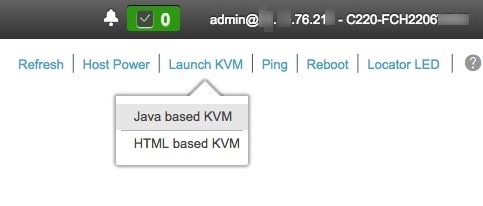
From the hyperlinked menu, choose and then select either Java based KVM or HTML based KVM. If you select Java-based KVM, you will need to launch the Java startup file from your browser or file manager in order to view the KVM console in its
own window. If you select HMTL-based KVM, it launches the KVM console in a separate window or tab automatically.
Irrespective of the KVM type you choose, use the KVM console to monitor the progress of the configuration and respond to the
Maglev Configuration wizard prompts.
|
| Step 3 |
With the KVM displayed, reboot the appliance by making one of the following selections:
-
In the main Cisco IMC GUI browser window: Choose , and switch to the KVM console to continue.
-
In the KVM console: Choose .
If you are asked to confirm your choice to reboot the appliance, click OK.
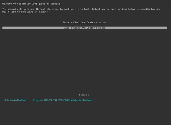
After displaying reboot messages, the KVM console displays the Maglev Configuration wizard welcome screen. 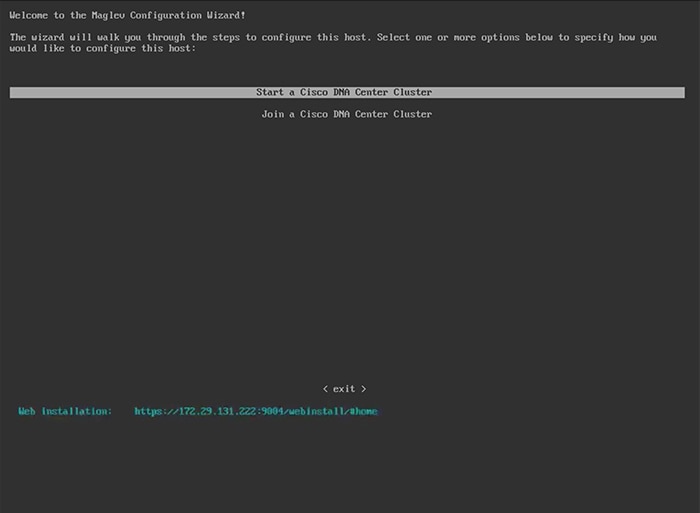
|
| Step 4 |
Click Start a Cisco DNA Center Cluster to begin configuring the primary node.
The wizard discovers all of the ports on the appliance and presents them to you one by one, in separate screens, in the following
order:
-
1-Gbps/10-Gbps Management Port (1, eno1/enp53s0f0, Network Adapter #1)
-
1-Gbps/10-Gbps Cloud Port (eno2/enp53s0f1, Network Adapter #2)
-
10-Gbps Enterprise Port (enp94s0f0/enp69s0f0, Network Adapter #3)
-
10-Gbps Cluster Port (enp94s0f1/enp69s0f1, Network Adapter #4)
| Note
|
The interface names assigned to ports on 44, 56, and 112 core appliances differ. Whenever two interface names are provided
in this procedure, the first applies to both 44 and 56 core appliances and the second applies to 112 core appliances.
|
If the wizard fails to display either or both of the Enterprise and Cluster ports during the course of configuration, these
ports may be non-functional or disabled. These two ports are required for Cisco DNA Center functionality. If you discover that they are non-functional, choose cancel to exit the configuration immediately. Be sure you have completed all of the steps provided in Execute Preconfiguration Checks before resuming configuration or contacting the Cisco Technical Assistance Center (TAC).
|
| Step 5 |
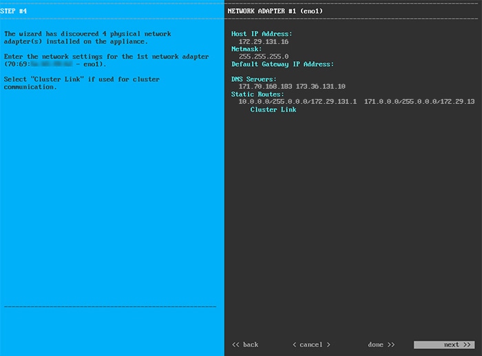
The wizard discovers the 1-Gbps/10-Gbps Management port (1, eno1/enp53s0f0) first and presents it as NETWORK ADAPTER #1. As explained in Interface Cable Connections, this port is used to access the Cisco DNA Center GUI from your management network. Apply the host IP address, netmask, and other values that are appropriate for this purpose
(see Required IP Addresses and Subnets and Required Configuration Information for the values to enter).
 Enter the configuration values for NETWORK ADAPTER
#1, as shown in the table below.
Table 1. Primary Node Entries for Network Adapter #1: 1-Gbps/10-Gbps Management Port (eno1/enp53s0f0)
|
Host IP address field
|
Enter the IP address for the Management port. This is
required.
|
|
Netmask field
|
Enter the netmask for the port's IP address. This is
required.
|
|
Default Gateway IP address field
|
Enter a default gateway IP address to use for the port.
| Important
|
Ensure that you enter a default gateway IP address for at least one of your appliance's interfaces. Otherwise, you will not
be able to complete the configuration wizard.
|
|
|
DNS Servers field
|
Enter the IP address of the preferred DNS server. If you
are entering multiple DNS servers, separate the IP
addresses in the list with spaces.
| Important
|
-
For NTP, ensure port 123 (UDP) is open between Cisco DNA Center and your NTP server.
-
For each appliance in your cluster, configure a
maximum of three DNS servers. Problems can occur
if you configure more than three DNS servers for
an appliance.
|
|
|
Static Routes field
|
Enter one or more static routes in the following format,
separated by spaces:
<network>/<netmask>/<gateway>.
|
|
Cluster Link field
|
Leave this field blank. It is required on the Cluster
port only.
|
After you finish entering the configuration values, click
next>> to proceed. The wizard validates the
values you entered and issues an error message if any are incorrect. If you
receive an error message, check that the value you entered is correct, then
reenter it. If needed, click <<back to reenter
it.
|
| Step 6 |
After successful validation of the Management port values you entered, the wizard presents the 1-Gbps/10-Gbps Cloud port (2,
eno2/enp53s0f1) as NETWORK ADAPTER #2. As explained in Interface Cable Connections, this is an optional port used to link the appliance to the Internet when you cannot do so through the 10-Gbps Enterprise
port (enp94s0f0/enp69s0f0). Apply the host IP address, netmask, and other values that are appropriate for this purpose (see
Required IP Addresses and Subnets and Required Configuration Information for the values to enter).
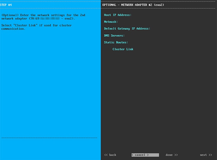 Enter the configuration values for NETWORK ADAPTER
#2, as shown in the table below.
Table 2. Primary Node Entries for Network Adapter #2: 1-Gbps/10-Gbps Cloud Port (eno2/enp53s0f1)
|
Host IP address field
|
Enter the IP address for the Cloud port. This is required
only if you are using the Cloud port for internet
connection; otherwise, you can leave it blank.
|
|
Netmask field
|
Enter the netmask for the port's IP address. This is
required if you enter an IP address.
|
|
Default Gateway IP address field
|
Enter a default gateway IP address to use for the Cloud port.
| Important
|
Ensure that you enter a default gateway IP address for at least one of your appliance's interfaces. Otherwise, you will not
be able to complete the configuration wizard.
|
|
|
DNS Servers field
|
Enter the IP address of the preferred DNS server. If you
are entering multiple DNS servers, separate the IP
addresses in the list with spaces.
| Important
|
For each appliance in your cluster, configure a
maximum of three DNS servers. Problems can occur if
you configure more than three DNS servers for an
appliance.
|
|
|
Static Routes field
|
Enter one or more static routes in the following format,
separated by spaces:
<network>/<netmask>/<gateway>.
This is usually required on the Management port
only.
|
|
Cluster Link field
|
Leave this field blank. It is required on the Cluster
port only.
|
After you provide the necessary information, click
next>> to proceed. Correct any validation
errors as you did in previous screens.
|
| Step 7 |
After successful validation of the Cloud port values you entered, the wizard presents the 10-Gbps Enterprise port (enp94s0f0/enp69s0f0)
as NETWORK ADAPTER #3. As explained in Interface Cable Connections, this is a required port used to link the appliance to the enterprise network. Apply the host IP address, netmask, and other
values that are appropriate for this purpose, (see Required IP Addresses and Subnets and Required Configuration Information for the values to enter).
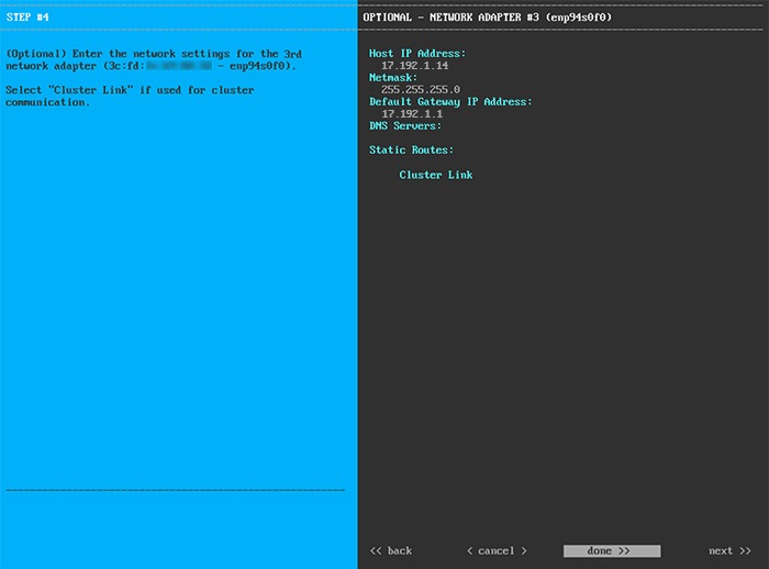 Enter the configuration values for NETWORK ADAPTER
#3, as shown in the table below.
Table 3. Primary Node Entries for Network Adapter #3: 10-Gbps Enterprise Port (enp94s0f0/enp69s0f0)
|
Host IP address field
|
Enter the IP address for the Enterprise port. This is
required.
|
|
Netmask field
|
Enter the netmask for the port's IP address. This is
required.
|
|
Default Gateway IP address field
|
Enter a default gateway IP address to use for the port.
| Important
|
Ensure that you enter a default gateway IP address for at least one of your appliance's interfaces. Otherwise, you will not
be able to complete the configuration wizard.
|
|
|
DNS Servers field
|
Enter the IP address of the preferred DNS server. If you
are entering multiple DNS servers, separate the IP
addresses in the list with spaces.
| Important
|
For each appliance in your cluster, configure a
maximum of three DNS servers. Problems can occur if
you configure more than three DNS servers for an
appliance.
|
|
|
Static Routes field
|
Enter one or more static routes in the following format,
separated by spaces:
<network>/<netmask>/<gateway>.
This is usually required on the Cisco DNA Center Management port only.
|
|
Cluster Link field
|
Leave this field blank. It is required on the Cluster
port only.
|
After you provide the necessary information, click
next>> to proceed. Correct any validation
errors as you did in previous screens.
|
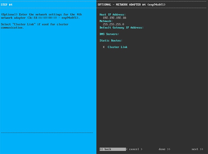
| Step 8 |
After successful validation of the Enterprise port values you entered, the wizard presents the 10-Gbps Cluster port (enp94s0f1/enp69s0f1)
and presents it as NETWORK ADAPTER #4. As explained in Interface Cable Connections, this port is used to link the appliance to the cluster, so apply the host IP address, netmask, and other values that are
appropriate for this purpose (see Required IP Addresses and Subnets and Required Configuration Information for the values to enter).
 Enter the configuration values for NETWORK ADAPTER
#4, as shown in the table below.
Table 4. Primary Node Entries for Network Adapter #4: 10-Gbps Cluster Port (enp94s0f1/enp69s0f1)
|
Host IP address field
|
Enter the IP address for the Cluster port. This is
required. Note that you cannot change the address of the
Cluster port later.
|
|
Netmask field
|
Enter the netmask for the port's IP address. This is
required.
|
|
Default Gateway IP address field
|
Enter a default gateway IP address to use for the port.
| Important
|
Ensure that you enter a default gateway IP address for at least one of your appliance's interfaces. Otherwise, you will not
be able to complete the configuration wizard.
|
|
|
DNS Servers field
|
Enter the IP address of the preferred DNS server. If you
are entering multiple DNS servers, separate the IP
addresses in the list with spaces.
| Important
|
For each appliance in your cluster, configure a
maximum of three DNS servers. Problems can occur if
you configure more than three DNS servers for an
appliance.
|
|
|
Static Routes field
|
Enter one or more static routes in the following format,
separated by spaces:
<network>/<netmask>/<gateway>.
This is usually required on the Management port
only.
|
|
Cluster Link field
|
Check the check box to indicate that this port will be
the link to a Cisco DNA Center cluster. This is required on the Cluster port
only.
|
After you provide the necessary information, click
next>> to proceed. Correct validation errors, if any, as
you did in previous screens. The wizard validates and applies your network
adapter configurations.
|
| Step 9 |
After the network adapter configuration is complete, the wizard prompts you to enter configuration values for the NETWORK PROXY you are using, as shown below.
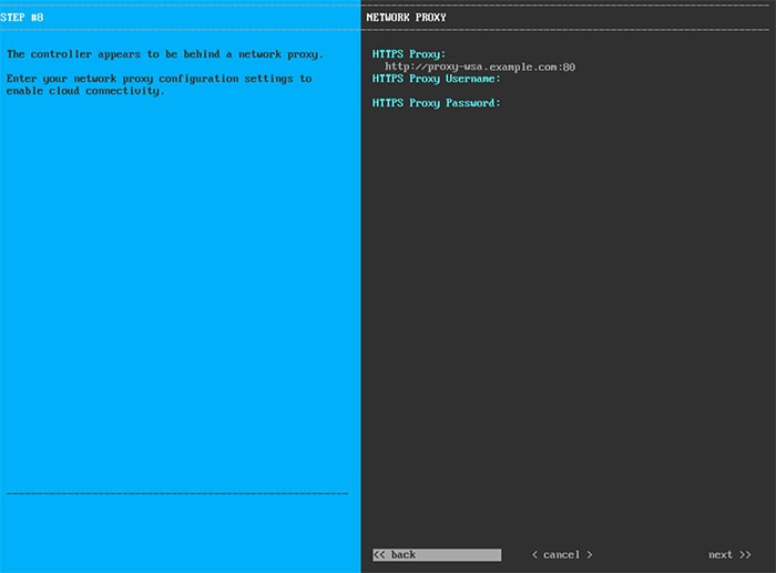 Enter the configuration values for the NETWORK PROXY, as shown in the table below.
Table 5. Primary Node Entries for Network Proxy
|
HTTPS Proxy field
|
Enter the URL or host name of an HTTPS network proxy used to access the Internet.
| Note
|
Connection from Cisco DNA Center to the HTTPS proxy is supported only via HTTP in this release.
|
|
|
HTTPS Proxy Username field
|
Enter the user name used to access the network proxy. If no proxy login is required, leave this field blank.
|
|
HTTPS Proxy Password field
|
Enter the password used to access the network proxy. If no proxy login is required, leave this field blank.
|
After you provide the necessary information, click next>> to proceed. Correct validation errors, if any, as you did in previous screens.
|
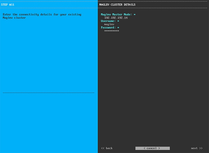
| Step 10 |
After network proxy configuration completes, the wizard prompts you to enter virtual IP addresses for the primary node, in
MAGLEV CLUSTER DETAILS, as shown below.
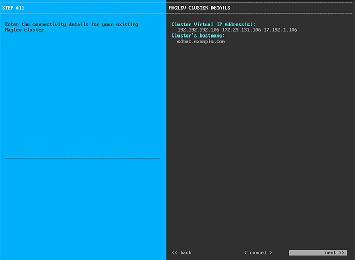 Enter a space-separated list of the virtual IP addresses used for traffic between the cluster and your network. This is required
for both three-node clusters and single-node clusters that will be converted into a three-node cluster in the future. If you
have a single-node cluster setup and plan to stick with it, skip this step and proceed to Step 11.
| Important
|
You must enter one virtual IP address for each configured network interface. You will not be able to complete the wizard unless
you do so. These addresses are tied to the cluster link's status, which must be in the UP state.
|
You also have the option to specify the fully qualified domain name (FQDN) for your cluster. Cisco DNA Center uses this domain name to do the following:
-
It uses this hostname to access your cluster’s web interface and the Representational State Transfer (REST) APIs used by devices
in the enterprise network that Cisco DNA Center manages.
-
In the Subject Alternative Name (SAN) field of Cisco DNA Center certificates, it uses the FQDN to the define the Plug and Play server that should be used for device provisioning.
After you provide the necessary information, click next>> to proceed. Correct validation errors, if any, as you did in previous screens.
|
| Step 11 |
After you have entered the virtual IP addresses, the wizard prompts you to enter USER ACCOUNT SETTINGS values, as shown below.
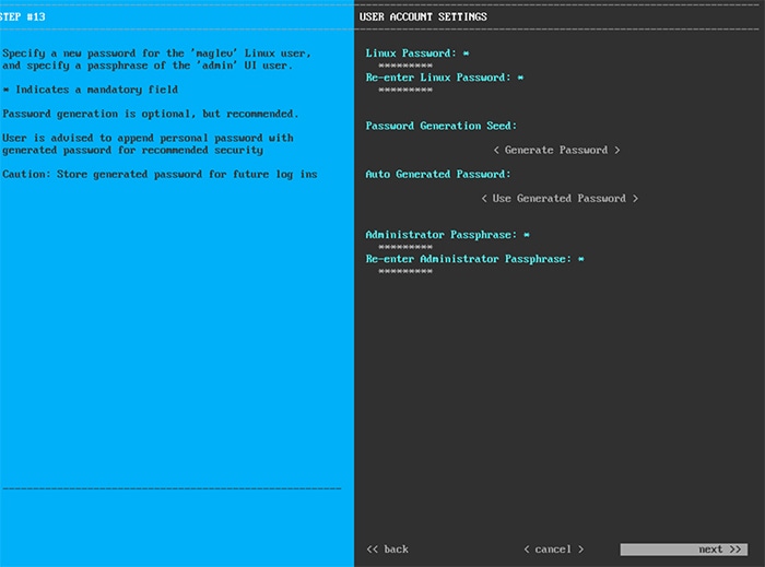 Enter the values for USER ACCOUNT SETTINGS, as shown in the table below.
Table 6. Primary Node Entries for User Account Settings
|
Linux Password field
|
Enter a Linux password for the maglev user.
|
|
Re-enter Linux Password field
|
Confirm the Linux password by entering it a second time.
|
|
Password Generation Seed field
|
If you do not want to create the Linux password yourself, enter a seed phrase in this field and then press <Generate Password> to generate the password.
|
|
Auto Generated Password field
|
(Optional) The seed phrase appears as part of a random and secure password. If desired, you can either use this password "as
is", or you can further edit this auto-generated password.
Press <Use Generated Password> to save the password.
|
|
Administrator Passphrase field
|
Enter a password for the default admin superuser, used to log in to Cisco DNA Center for the first time.
|
|
Re-enter Administrator Passphrase field
|
Confirm the administrator passphrase by entering it a second time.
|
After you provide the necessary information, click next>> to proceed. Correct validation errors, if any, as you did in previous screens.
|
| Step 12 |
After you have entered the user account details, the wizard prompts you to enter NTP SERVER SETTINGS values, as shown below.
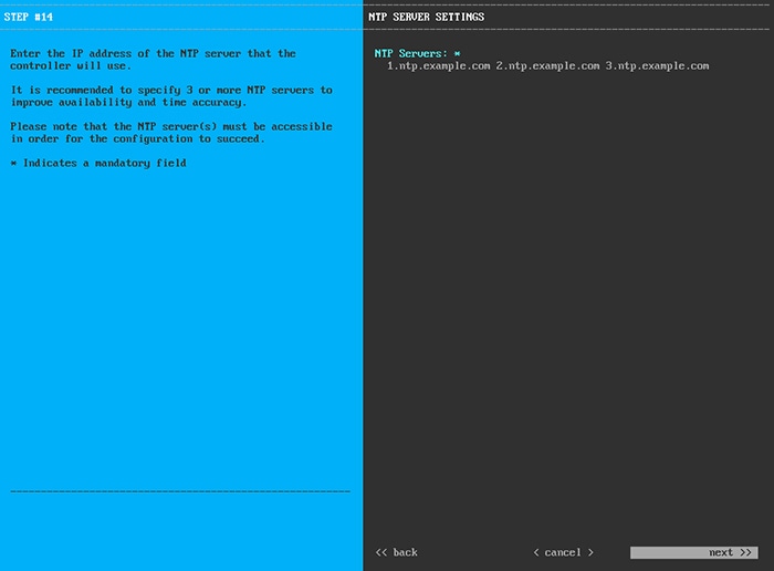 Enter one or more NTP server addresses or hostnames, separated by spaces. At least one NTP address or hostname is required.
For a production deployment, we recommend that you configure a minimum of three NTP servers.
After you provide the necessary information, click next>> to proceed. Correct validation errors, if any, as you did in previous screens. The wizard validates and applies your NTP
server configuration.
|
| Step 13 |
After you have specified the appropriate NTP servers, the wizard prompts you to enter MAGLEV ADVANCED SETTINGS values, as shown below.
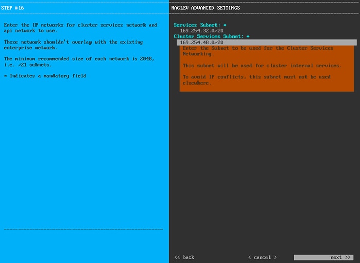 Enter the configuration values for MAGLEV ADVANCED SETTINGS, as shown in the table below.
Table 7. Primary Node Entries for Maglev Advanced Settings
|
Services Subnet field
|
A dedicated, non-routed IP subnet that Cisco DNA Center uses to manage internal services. By default, this is already set to 169.254.32.0/20, and we recommend that you use this subnet. If you choose to enter another subnet, ensure that it does not conflict with
or overlap any other subnet used by the Cisco DNA Center internal network or an external network. For more information, see the Services Subnet description in Required IP Addresses and Subnets.
|
|
Cluster Services Subnet field
|
A dedicated, non-routed IP subnet that Cisco DNA Center uses to manage internal cluster services. By default, this is already set to 169.254.48.0/20, and we recommend that you use this subnet. If you choose to enter another subnet, ensure that it does not conflict with
or overlap any other subnet used by the Cisco DNA Center internal network or an external network. For more information, see the Cluster Services Subnet description in Required IP Addresses and Subnets.
|
When you are finished, cllick next>> to proceed. Correct validation errors, if any, as you did in previous screens.
|
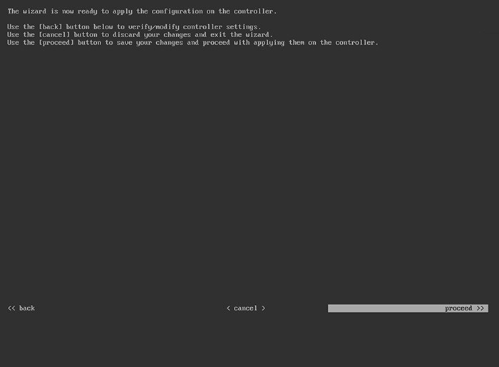
| Step 14 |
After you have entered the Maglev advanced settings, a final message appears, stating that the wizard is ready to apply the
configuration (as shown below).
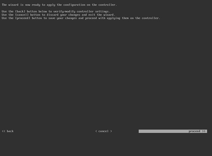 Click proceed>> to complete the configuration wizard.
The host will reboot automatically and display messages on the KVM console as it applies your settings and brings up services.
This process can take several hours. You can monitor its progress via the KVM console.
At the end of the configuration process, the appliance power-cycles again, then displays a CONFIGURATION SUCCEEDED! message.
|


 Feedback